EP4517948A1 - Secondary battery module and secondary battery used therefor - Google Patents
Secondary battery module and secondary battery used therefor Download PDFInfo
- Publication number
- EP4517948A1 EP4517948A1 EP23812162.8A EP23812162A EP4517948A1 EP 4517948 A1 EP4517948 A1 EP 4517948A1 EP 23812162 A EP23812162 A EP 23812162A EP 4517948 A1 EP4517948 A1 EP 4517948A1
- Authority
- EP
- European Patent Office
- Prior art keywords
- edge part
- secondary battery
- incombustible material
- battery module
- electrode assembly
- Prior art date
- Legal status (The legal status is an assumption and is not a legal conclusion. Google has not performed a legal analysis and makes no representation as to the accuracy of the status listed.)
- Pending
Links
Images



Classifications
-
- H—ELECTRICITY
- H01—ELECTRIC ELEMENTS
- H01M—PROCESSES OR MEANS, e.g. BATTERIES, FOR THE DIRECT CONVERSION OF CHEMICAL ENERGY INTO ELECTRICAL ENERGY
- H01M10/00—Secondary cells; Manufacture thereof
- H01M10/04—Construction or manufacture in general
- H01M10/0481—Compression means other than compression means for stacks of electrodes and separators
-
- H—ELECTRICITY
- H01—ELECTRIC ELEMENTS
- H01M—PROCESSES OR MEANS, e.g. BATTERIES, FOR THE DIRECT CONVERSION OF CHEMICAL ENERGY INTO ELECTRICAL ENERGY
- H01M50/00—Constructional details or processes of manufacture of the non-active parts of electrochemical cells other than fuel cells, e.g. hybrid cells
- H01M50/10—Primary casings; Jackets or wrappings
- H01M50/116—Primary casings; Jackets or wrappings characterised by the material
- H01M50/117—Inorganic material
-
- H—ELECTRICITY
- H01—ELECTRIC ELEMENTS
- H01M—PROCESSES OR MEANS, e.g. BATTERIES, FOR THE DIRECT CONVERSION OF CHEMICAL ENERGY INTO ELECTRICAL ENERGY
- H01M50/00—Constructional details or processes of manufacture of the non-active parts of electrochemical cells other than fuel cells, e.g. hybrid cells
- H01M50/10—Primary casings; Jackets or wrappings
- H01M50/116—Primary casings; Jackets or wrappings characterised by the material
- H01M50/124—Primary casings; Jackets or wrappings characterised by the material having a layered structure
-
- H—ELECTRICITY
- H01—ELECTRIC ELEMENTS
- H01M—PROCESSES OR MEANS, e.g. BATTERIES, FOR THE DIRECT CONVERSION OF CHEMICAL ENERGY INTO ELECTRICAL ENERGY
- H01M50/00—Constructional details or processes of manufacture of the non-active parts of electrochemical cells other than fuel cells, e.g. hybrid cells
- H01M50/10—Primary casings; Jackets or wrappings
- H01M50/116—Primary casings; Jackets or wrappings characterised by the material
- H01M50/124—Primary casings; Jackets or wrappings characterised by the material having a layered structure
- H01M50/1245—Primary casings; Jackets or wrappings characterised by the material having a layered structure characterised by the external coating on the casing
-
- H—ELECTRICITY
- H01—ELECTRIC ELEMENTS
- H01M—PROCESSES OR MEANS, e.g. BATTERIES, FOR THE DIRECT CONVERSION OF CHEMICAL ENERGY INTO ELECTRICAL ENERGY
- H01M50/00—Constructional details or processes of manufacture of the non-active parts of electrochemical cells other than fuel cells, e.g. hybrid cells
- H01M50/10—Primary casings; Jackets or wrappings
- H01M50/14—Primary casings; Jackets or wrappings for protecting against damage caused by external factors
- H01M50/143—Fireproof; Explosion-proof
-
- H—ELECTRICITY
- H01—ELECTRIC ELEMENTS
- H01M—PROCESSES OR MEANS, e.g. BATTERIES, FOR THE DIRECT CONVERSION OF CHEMICAL ENERGY INTO ELECTRICAL ENERGY
- H01M50/00—Constructional details or processes of manufacture of the non-active parts of electrochemical cells other than fuel cells, e.g. hybrid cells
- H01M50/20—Mountings; Secondary casings or frames; Racks, modules or packs; Suspension devices; Shock absorbers; Transport or carrying devices; Holders
- H01M50/289—Mountings; Secondary casings or frames; Racks, modules or packs; Suspension devices; Shock absorbers; Transport or carrying devices; Holders characterised by spacing elements or positioning means within frames, racks or packs
- H01M50/293—Mountings; Secondary casings or frames; Racks, modules or packs; Suspension devices; Shock absorbers; Transport or carrying devices; Holders characterised by spacing elements or positioning means within frames, racks or packs characterised by the material
-
- H—ELECTRICITY
- H01—ELECTRIC ELEMENTS
- H01M—PROCESSES OR MEANS, e.g. BATTERIES, FOR THE DIRECT CONVERSION OF CHEMICAL ENERGY INTO ELECTRICAL ENERGY
- H01M50/00—Constructional details or processes of manufacture of the non-active parts of electrochemical cells other than fuel cells, e.g. hybrid cells
- H01M50/30—Arrangements for facilitating escape of gases
- H01M50/35—Gas exhaust passages comprising elongated, tortuous or labyrinth-shaped exhaust passages
- H01M50/358—External gas exhaust passages located on the battery cover or case
-
- H—ELECTRICITY
- H01—ELECTRIC ELEMENTS
- H01M—PROCESSES OR MEANS, e.g. BATTERIES, FOR THE DIRECT CONVERSION OF CHEMICAL ENERGY INTO ELECTRICAL ENERGY
- H01M50/00—Constructional details or processes of manufacture of the non-active parts of electrochemical cells other than fuel cells, e.g. hybrid cells
- H01M50/50—Current conducting connections for cells or batteries
- H01M50/531—Electrode connections inside a battery casing
- H01M50/533—Electrode connections inside a battery casing characterised by the shape of the leads or tabs
-
- H—ELECTRICITY
- H01—ELECTRIC ELEMENTS
- H01M—PROCESSES OR MEANS, e.g. BATTERIES, FOR THE DIRECT CONVERSION OF CHEMICAL ENERGY INTO ELECTRICAL ENERGY
- H01M50/00—Constructional details or processes of manufacture of the non-active parts of electrochemical cells other than fuel cells, e.g. hybrid cells
- H01M50/50—Current conducting connections for cells or batteries
- H01M50/531—Electrode connections inside a battery casing
- H01M50/534—Electrode connections inside a battery casing characterised by the material of the leads or tabs
-
- H—ELECTRICITY
- H01—ELECTRIC ELEMENTS
- H01M—PROCESSES OR MEANS, e.g. BATTERIES, FOR THE DIRECT CONVERSION OF CHEMICAL ENERGY INTO ELECTRICAL ENERGY
- H01M50/00—Constructional details or processes of manufacture of the non-active parts of electrochemical cells other than fuel cells, e.g. hybrid cells
- H01M50/50—Current conducting connections for cells or batteries
- H01M50/572—Means for preventing undesired use or discharge
- H01M50/584—Means for preventing undesired use or discharge for preventing incorrect connections inside or outside the batteries
- H01M50/588—Means for preventing undesired use or discharge for preventing incorrect connections inside or outside the batteries outside the batteries, e.g. incorrect connections of terminals or busbars
-
- H—ELECTRICITY
- H01—ELECTRIC ELEMENTS
- H01M—PROCESSES OR MEANS, e.g. BATTERIES, FOR THE DIRECT CONVERSION OF CHEMICAL ENERGY INTO ELECTRICAL ENERGY
- H01M50/00—Constructional details or processes of manufacture of the non-active parts of electrochemical cells other than fuel cells, e.g. hybrid cells
- H01M50/50—Current conducting connections for cells or batteries
- H01M50/572—Means for preventing undesired use or discharge
- H01M50/584—Means for preventing undesired use or discharge for preventing incorrect connections inside or outside the batteries
- H01M50/59—Means for preventing undesired use or discharge for preventing incorrect connections inside or outside the batteries characterised by the protection means
- H01M50/595—Tapes
-
- Y—GENERAL TAGGING OF NEW TECHNOLOGICAL DEVELOPMENTS; GENERAL TAGGING OF CROSS-SECTIONAL TECHNOLOGIES SPANNING OVER SEVERAL SECTIONS OF THE IPC; TECHNICAL SUBJECTS COVERED BY FORMER USPC CROSS-REFERENCE ART COLLECTIONS [XRACs] AND DIGESTS
- Y02—TECHNOLOGIES OR APPLICATIONS FOR MITIGATION OR ADAPTATION AGAINST CLIMATE CHANGE
- Y02E—REDUCTION OF GREENHOUSE GAS [GHG] EMISSIONS, RELATED TO ENERGY GENERATION, TRANSMISSION OR DISTRIBUTION
- Y02E60/00—Enabling technologies; Technologies with a potential or indirect contribution to GHG emissions mitigation
- Y02E60/10—Energy storage using batteries
Definitions
- the present invention relates to a secondary battery module and a secondary battery used therein, and more particularly, to a secondary battery module including a plurality of secondary batteries and a housing accommodating the plurality of secondary batteries, and a secondary battery used therein.
- the battery module may be constituted by a plurality of secondary batteries, a busbar (or metal plate) for connecting the secondary batteries in series and/or parallel, a sensing assembly for sensing a voltage and temperature, an electric component for controlling charging/discharging, and a housing for accommodating the above components.
- a busbar or metal plate
- the battery module may be constituted by a plurality of secondary batteries, a busbar (or metal plate) for connecting the secondary batteries in series and/or parallel, a sensing assembly for sensing a voltage and temperature, an electric component for controlling charging/discharging, and a housing for accommodating the above components.
- the battery module may be constituted by a plurality of secondary batteries, a busbar (or metal plate) for connecting the secondary batteries in series and/or parallel, a sensing assembly for sensing a voltage and temperature, an electric component for controlling charging/discharging, and a housing for accommodating the above components.
- the pouch-type secondary batteries are being widely used in medium and large-sized battery modules because of their high energy
- a technology capable of delaying a flame or heat propagation time between the secondary batteries inside the secondary battery module is required so that the driver evacuates before the flame is exposed to the outside of the housing.
- the present invention has been made to solve the above problems, and an object of the present invention is to provide a secondary battery module capable of delaying a flame or heat propagation time between secondary batteries inside the secondary battery module.
- a secondary battery module may include: a plurality of secondary batteries arranged side by side along one direction; and a housing configured to accommodate the plurality of secondary batteries.
- At least one of the plurality of secondary batteries may include: an electrode assembly; and a battery case including an accommodation part in which, the electrode assembly is accommodated, and an edge part connected from the accommodation part, the battery case having an outer surface coated with an incombustible material.
- the incombustible material applied to the edge part may have a thickness greater than that of the incombustible material applied to the accommodation part.
- the edge part may include: a first edge part from which an electrode lead connected to the electrode assembly protrudes; and a second edge part connected to the first edge part and folded at least once.
- the incombustible material may not be applied to an end of the second edge part.
- the edge part may include: a first edge part from which an electrode lead connected to the electrode assembly protrudes; and a second edge part connected to the first edge part and folded at least once.
- the incombustible material applied to the first edge part may have a thickness greater than that of the incombustible material applied to the second edge part.
- the incombustible material may not be applied to an electrode lead connected to the electrode assembly and protruded to the outside of the edge part.
- the incombustible material may not be applied to an insulating member configured to insulate the electrode lead from the edge part.
- the secondary battery module may further include at least one compression pad disposed adjacent to the secondary battery, wherein an outer surface of the compression pad may be coated with the incombustible material.
- the incombustible material may include ceramic.
- Surfaces of the secondary battery and the compression pad, which are coated with the incombustible material, may be disposed to face each other.
- the compression pad may have a height greater than that of the secondary battery.
- At least one or more through-holes that pass through the inside and outside of the housing may be defined in at least one area of the housing.
- the at least one or more through-holes may be defined in a top surface of the housing.
- the housing may include: a main body configured to surround a portion of a surface of the secondary battery; and a cover part connected to the main body to cover a remaining surface of the secondary battery.
- the at least one or more through-holes may be defined in the cover part.
- the through-holes may be defined in a position facing the battery case.
- the through-holes may be defined in a position facing the edge part.
- a secondary battery may include: an electrode assembly; a battery case including an accommodation part in which the electrode assembly is accommodated, and an edge part connected from the accommodation part, the battery case having an outer surface coated with an incombustible material.
- the incombustible material applied to the edge part may have a thickness greater than that of the incombustible material applied to the accommodation part.
- the edge part may include: a first edge part from which an electrode lead connected to the electrode assembly protrudes; and a second edge part connected to the first edge part and folded at least once.
- the incombustible material may not be applied to an end of the second edge part.
- the edge part may include: a first edge part from which an electrode lead connected to the electrode assembly protrudes; and a second edge part connected to the first edge part and folded at least once.
- the incombustible material applied to the first edge part may have a thickness greater than that of the incombustible material applied to the second edge part.
- the incombustible material may not be applied to an electrode lead connected to the electrode assembly and protruded to the outside of the edge part.
- the incombustible material may not be applied to an insulating member which is configured to insulate the electrode lead from the edge part and of which a portion protrudes to the outside of the edge part.
- the incombustible material may include ceramic.
- the present invention may have the advantage in that the flame or heat propagation time between the secondary batteries is delayed by applying the incombustible material to at least one of the secondary batteries to improve the stability of the secondary battery module.
- the present invention may have the advantage in that the flame or heat propagation time between the secondary batteries is delayed by applying the incombustible material to the compression pad to improve the stability of the secondary battery module.
- the present invention may have the advantage in that the through-hole is defined to pass through the inside and outside of the housing in at least one region of the housing to discharge the gas inside the housing to the outside so as to prevent the gas compression in the housing, and the through-hole is defined toward the battery case, particularly the edge part to minimize the risk of sparking of the electrode lead and the gas.
- the secondary batteries may be configured to be arranged side by side along one direction inside the housing 120 and may include an electrode assembly (not shown) and a battery case 111 accommodating the electrode assembly.
- the type of the electrode assembly is not limited.
- the electrode assembly may have a structure of any one of a jelly-roll type (winding type), a stack type (stacked type), or a complex type (stack/folding type).
- the electrode assembly may have a configuration in which electrodes and separators are alternately disposed.
- the electrode assembly may have a configuration in which positive electrodes and negative electrodes are alternately disposed with separators therebetween.
- the electrode assembly may have a structure in which positive electrode collector/positive electrode active material layer/separator/negative electrode active material layer/negative electrode collector are sequentially stacked so that the positive electrode active material layer disposed one surface of the separator faces the negative electrode active material layer disposed on the other surface of the separator.
- the battery case 111 may have a structure including an accommodation part 112 accommodating the electrode assembly and an edge part 113 connected from an edge of the accommodation part 112.
- the battery case 111 may include the accommodation part 112 provided by forming one region of a laminate sheet in which an inner resin layer/metal layer/outer resin layer are sequentially stacked from the inside to the outside and the edge part 113 connected to the edge of the accommodation part 112.
- polypropylene may be used for the inner resin layer
- polyethylene terephthalate PET
- aluminum Al
- the materials of the inner resin layer, the outer resin layer, and the metal layer are not limited thereto, and when each of the inner resin layer and the outer resin layer has an insulating material, and the metal layer has a metal material, the materials may be used without particular limitation.
- accommodation part 112 may be understood as a region having an empty space by being formed concavely so that the electrode assembly is accommodated in the battery case 111.
- the edge part 113 may be understood as a region connected from the edge of the accommodation part 112 on the battery case 111.
- the edge part 113 may have a sealed structure, of which an edge is sealed, to prevent the electrode assembly accommodated in the accommodation part 112 from being damaged due to exposure to external moisture or air.
- the edge part 113 may include a first edge part 113a, from which an electrode lead 114 to be described later protrudes, and a second edge part 113b connected to the first edge part 113a and folded at least once.
- the second edge part 113b may be double side-folded (DSF).
- first edge part 113a may be provided at both sides of the secondary battery 110 in a full-length direction
- second edge part 113b may be provided at at least one side of the secondary battery 110 in a full-width direction.
- An outer surface of the battery case 111 may be coated with an incombustible material.
- the incombustible material may include a ceramic material.
- the incombustible material may include a ceramic material.
- the metal layer may be exposed at an end of the edge part 113a due to the structure of the battery case 111, and when the battery case 111 is manufactured, in the process of stacking the outer resin layer on the metal layer, a through-hole called a pin hole may be defined in the outer resin layer to expose the metal layer to the outside.
- the incombustible material made of ceramic may be applied on the metal layer exposed to the outside insulate the metal layer from the outside, thereby improving insulation performance of the secondary battery 110.
- the incombustible material may not be applied to an end 113c of the second edge part 113b. Therefore, when a gas is generated in the secondary battery 110 due to an abnormally high temperature or fire, the end of the second edge part 113b is preferentially broken to induce the gas to be discharged. Thus, the gas may be discharged to the first edge part 113a to prevent flame from being spread through the electrode lead 114.
- the secondary battery 110 may include the electrode lead 114 protruding from the battery case 111.
- the secondary battery 110 may further include an insulating member 115 that insulates the electrode lead 114 from the edge part 113 of the battery case 111, more specifically, the first edge part 113a.
- the electrode lead 114 may be understood as a configuration that protrudes from the battery case 111 and is electrically connected to the electrode assembly described above.
- the electrode lead 114 may have one end connected to electrode tabs (not shown) disposed on the electrode and the other end protruding out of the pouch so as to be connected to the other secondary battery 110 or external device.
- the insulating member 115 may surround a portion of the electrode lead 114.
- the insulating member 115 may be disposed between the edge part 113 and the electrode lead 114.
- a portion of the edge part 113, more specifically, a portion of the first edge part 113a may be sealed with the insulating member 115.
- the insulating member 115 may be an insulating film or an insulating tape. A portion of the insulating member 115 may protrude outward from the edge part 113.
- the incombustible material may not be applied to the electrode lead 114, further more, to the insulating member 115.
- the secondary batteries 110 as described above may be arranged side by side along one direction, as illustrated in FIG. 2 , in order to improve energy density of the secondary battery module 100 in the accommodation space inside the housing 120.
- one direction may be understood as a direction parallel to a Y-axis of FIG. 2 .
- At this time, at least one of the secondary batteries 110 may be coated with the incombustible material on the outer surface to delay or prevent the propagation of flame or heat to other secondary batteries 110 adjacent thereto even if one secondary battery 110 starts to ignite.
- all of the secondary batteries 110 arranged in one direction may be coated with the incombustible material, or only some of the secondary batteries 110 arranged in one direction may be coated with the incombustible material.
- the entire outer surface of the secondary battery 110 may be coated with the incombustible material, or only a portion of the outer surface may be coated with the incombustible material.
- the incombustible material may be any material as long as the incombustible material is capable of delaying the flame or heat propagation between the secondary batteries 110, which are adjacent to each other, and may include, for example, a ceramic material.
- the incombustible material may be applied to the secondary battery 110 in various manners.
- the incombustible material may be spray-applied to the secondary battery 110 by a spraying device.
- an incombustible coating layer 110a may be formed on the outer surface of the secondary battery 110.
- a support member such as a gripper may grip the electrode lead 114 and/or the insulating member 115 to support the secondary battery 110.
- the incombustible material may be entirely applied to the battery case 111 without interfering with the support member.
- the incombustible material may be prevented from being applied to the electrode lead 114 without a separate masking member.
- the thickness of the incombustible coating layer 110a is less than 0.01 mm, the coating of the incombustible material is not smoothly performed in the process, and an uncoated area may occur on the outer surface of the secondary battery 110, and when the thickness exceeds 1 mm, the thickness of the incombustible coating layer 110a becomes too thick, a side effect of being separated from the outer surface of the secondary battery 110 occurs.
- the thickness of the incombustible coating layer 110a on the edge part 113 may be thicker than the thickness of the incombustible coating layer 110a on the accommodation part 112. That is, the thickness of the incombustible material applied to the edge part 113 may be thicker than the thickness of the incombustible material applied to the accommodation part 112.
- the edge part 113 having a sealed structure by sealing is more vulnerable to breakage than the accommodation part 112, and thus, there is a risk that flames is preferentially emitted or invaded from the edge part 113.
- the thick incombustible coating layer 110a is formed on the edge part 113 to delay the breakage of the sealing and also delay the propagation of the flame.
- the thickness of the incombustible coating layer 110a on the first edge part 113a may be thicker than the thickness of the nonflammable coating layer 110a on the second edge part 113b. That is, the thickness of the incombustible material applied to the first edge part 113a may be greater than the thickness of the incombustible material applied to the second edge part 113b.
- the first edge part 113a from which the electrode lead 114 protrudes is vulnerable to the propagation of the flame, and there is a possibility that the sealing strength is relatively lower than that of the second edge part 113b folded at least once.
- the thicker incombustible coating layer 110a may be formed on the first edge part 113a to delay the breakage of the sealing and also delay the propagation of the flame.
- the secondary battery module 100 may further include at least one compression pad 130 disposed adjacent to the secondary battery 110.
- the compression pad 130 is disposed adjacent to the secondary battery 110 in an accommodation space S of the housing 120, and various configurations are possible.
- the compression pad 130 may be made of a deformable material to prevent the module from being damaged by flexibly compensating for the space when swelling of the secondary battery 110 occurs.
- the compression pad 130 may be made of a polyurethane material.
- the outer surface of the compression pad 130 may also be coated with the incombustible material in order to delay or prevent the propagation of the flame or heat between the secondary batteries 110.
- the compression pad 130 when the compression pad 130 is provided in plurality, all of the plurality of compression pads 130 may be coated with the incombustible material, or only some of the plurality of compression pads 130 may be coated with the incombustible material.
- the entire outer surface of the compression pad 130 may be coated with the incombustible material, or only a portion of the outer surface may be coated with the incombustible material.
- the incombustible material may be any material as long as the incombustible material is capable of delaying the flame or heat propagation between the secondary batteries 110, which are described above, and may include, for example, a ceramic material.
- the incombustible material may be applied to the compression pad 130 in various manners.
- the incombustible material may be spray-applied to the compression pad 130 by a spraying device.
- an incombustible coating layer 130a may be formed on the outer surface of the compression pad 130.
- the incombustible coating layer 130a may be applied to the compression pad 130 in various thicknesses, but it may be preferable that the incombustible coating layer 130a is formed on the outer surface of the compression pad 130 to a thickness of 0.01 mm to 1 mm.
- the thickness of the incombustible coating layer 130a is less than 0.01 mm, the coating of the incombustible material is not smoothly performed in the process, and an uncoated area may occur on the outer surface of the compression pad 130, and when the thickness exceeds 1 mm, the thickness of the incombustible coating layer 130a becomes too thick, a side effect of being separated from the outer surface of the compression pad 130 occurs.
- the compression pad 130 may have various heights and widths.
- a height H2 of the compression pad 130 may be higher than a height H1 of the secondary battery 110, as illustrated in FIGS. 4a to 4b (H2>H1).
- the compression pad 130 may be disposed between the plurality of secondary batteries 110 or between the secondary batteries 110 and the housing 120.
- the compression pad 130 may be disposed adjacent to the secondary battery 110 coated with the incombustible material.
- the secondary battery 110 and the compression pad 130 may be disposed so that surfaces coated with the incombustible material are disposed to face each other to effectively delay the propagation of the flame or heat between the secondary batteries 110.
- the housing 120 is configured to accommodate the plurality of secondary batteries 110 and/or the compression pad 130, and various configurations are possible.
- the housing 120 may have a structure in which the accommodation space S is defined therein to accommodate the plurality of secondary batteries 110 and/or the compression pad 130.
- the housing 120 may include a main body 121 surrounding a portion of a surface of the secondary battery 110 and a cover part 122 connected to the main body 121 to cover the remaining surface of the secondary battery 110.
- the main body 121 may include a bottom portion (not shown) parallel to an X-Y plane of FIG. 5 and a pair of side portions (not shown) extending from both ends of the bottom portion in an upward direction (Z direction in FIG. 5 ).
- the main body 121 may be formed in a ' ' shape to surround a portion of the surface of the secondary battery 110.
- cover part 122 may be connected to the side portion and be provided in a ' '-shaped opening to cover the remaining surface of the secondary battery 110.
- the cover part 122 may be provided at an upper side of the main body 121 to cover a top surface of the secondary battery 110.
- a surface of the main body 121 that is not covered by the cover part 122 may be covered by an end plate 123.
- the end plate 123 may be provided at the bottom portion of the main body 121 so as to be connected to both ends on which the side surfaces are not formed, and as illustrated in FIG. 6 , the end plate 123 may be disposed on an area corresponding to the electrode lead 114.
- the housing 120 having the above structure has at least one or more through-holes P in at least one region so that a gas generated by ignition in the secondary battery 110 is discharged from the accommodation space S to the outside.
- At least one or more through-holes P may be defined in a top surface of the housing 120 in consideration of a difference in density between the gas, which is generated in the secondary battery 110, and air, prevention of secondary damage due to the gas discharge from the secondary battery 110, and ease in manufacturing process. That is, when the housing 120 has a structure including the main body 121 and the cover part 122 as described above, at least one or more through-holes P may be defined in the cover part 122.
- the accommodation part 112 on the battery case 111 is a region in which the electrode assembly is accommodated, as illustrated in FIG. 7 , it may be more preferable that the through-hole P is defined at a position facing the edge part 113 to protect the electrode assembly from the outside.
- the through-hole P may be defined at a position facing the edge part 113 disposed in a width direction (Z direction in FIG. 1 ) of the secondary battery 110.
- the secondary battery module 100 of the present invention may include a plurality of secondary batteries 110 arranged side by side along one direction; a housing 120 accommodating the plurality of secondary batteries 110; and at least one compression pad 130 disposed adjacent to the secondary battery 110, and an outer surface of the compression pad 130 is coated with an incombustible material.
- the compression pad 130 may be coated with the incombustible material including ceramic, and a height of the compression pad 130 may be higher than that of the adjacent secondary battery 110.
- at least one or more through-holes P passing through the inside and outside of the housing may be defined in at least one area of the housing 120.
Landscapes
- Chemical & Material Sciences (AREA)
- Chemical Kinetics & Catalysis (AREA)
- Electrochemistry (AREA)
- General Chemical & Material Sciences (AREA)
- Inorganic Chemistry (AREA)
- Engineering & Computer Science (AREA)
- Manufacturing & Machinery (AREA)
- Battery Mounting, Suspending (AREA)
- Connection Of Batteries Or Terminals (AREA)
- Sealing Battery Cases Or Jackets (AREA)
Abstract
Description
- The present application claims the benefit of the priority of
Korean Patent Application Nos. 10-2022-0064228, filed on May 25, 2022 10-2022-0153107, filed on November 15, 2022 - The present invention relates to a secondary battery module and a secondary battery used therein, and more particularly, to a secondary battery module including a plurality of secondary batteries and a housing accommodating the plurality of secondary batteries, and a secondary battery used therein.
- In recent, secondary batteries have attracted considerable attention as power sources for electric vehicles (EVs), hybrid electric vehicles (HEVs), and the like, which have been developed to solve limitations, such as air pollution, caused by existing gasoline and diesel vehicles that use fossil fuels.
- While one or two to three or four secondary batteries are used in a small mobile device, a battery module in which a plurality of secondary battery cells are electrically connected to each other, or a battery pack in which a plurality of battery modules are electrically connected to each other is used due to needs for high power and large capacity in medium and large devices such as the electric vehicles.
- For example, the battery module may be constituted by a plurality of secondary batteries, a busbar (or metal plate) for connecting the secondary batteries in series and/or parallel, a sensing assembly for sensing a voltage and temperature, an electric component for controlling charging/discharging, and a housing for accommodating the above components. Among the currently commercialized secondary batteries, one of the most spotlighted secondary batteries may be lithium secondary batteries, which are capable of being classified into can-type secondary batteries and pouch-type secondary batteries according to their shapes of exterior materials. Among them, the pouch-type secondary batteries are being widely used in medium and large-sized battery modules because of their high energy density and easy stacking.
- As demands for secondary battery modules mounted on vehicles have recently increased, customers are requiring to increase in energy density of the secondary batteries within a limited space of the secondary battery module. In this case, there is a problem in that safety risks related to ignition and explosion of the secondary battery also increase together.
- That is, in order to secure safety of a vehicle driver when the secondary battery inside the secondary battery module is ignited, a technology capable of delaying a flame or heat propagation time between the secondary batteries inside the secondary battery module is required so that the driver evacuates before the flame is exposed to the outside of the housing.
- The present invention has been made to solve the above problems, and an object of the present invention is to provide a secondary battery module capable of delaying a flame or heat propagation time between secondary batteries inside the secondary battery module.
- A secondary battery module according to an embodiment of the present invention may include: a plurality of secondary batteries arranged side by side along one direction; and a housing configured to accommodate the plurality of secondary batteries. At least one of the plurality of secondary batteries may include: an electrode assembly; and a battery case including an accommodation part in which, the electrode assembly is accommodated, and an edge part connected from the accommodation part, the battery case having an outer surface coated with an incombustible material. The incombustible material applied to the edge part may have a thickness greater than that of the incombustible material applied to the accommodation part.
- The edge part may include: a first edge part from which an electrode lead connected to the electrode assembly protrudes; and a second edge part connected to the first edge part and folded at least once. The incombustible material may not be applied to an end of the second edge part.
- The edge part may include: a first edge part from which an electrode lead connected to the electrode assembly protrudes; and a second edge part connected to the first edge part and folded at least once. The incombustible material applied to the first edge part may have a thickness greater than that of the incombustible material applied to the second edge part.
- The incombustible material may not be applied to an electrode lead connected to the electrode assembly and protruded to the outside of the edge part.
- The incombustible material may not be applied to an insulating member configured to insulate the electrode lead from the edge part.
- The secondary battery module may further include at least one compression pad disposed adjacent to the secondary battery, wherein an outer surface of the compression pad may be coated with the incombustible material.
- The incombustible material may include ceramic.
- Surfaces of the secondary battery and the compression pad, which are coated with the incombustible material, may be disposed to face each other.
- The compression pad may have a height greater than that of the secondary battery.
- At least one or more through-holes that pass through the inside and outside of the housing may be defined in at least one area of the housing.
- The at least one or more through-holes may be defined in a top surface of the housing.
- The housing may include: a main body configured to surround a portion of a surface of the secondary battery; and a cover part connected to the main body to cover a remaining surface of the secondary battery. The at least one or more through-holes may be defined in the cover part.
- The through-holes may be defined in a position facing the battery case.
- The through-holes may be defined in a position facing the edge part.
- A secondary battery according to an embodiment of the present invention may include: an electrode assembly; a battery case including an accommodation part in which the electrode assembly is accommodated, and an edge part connected from the accommodation part, the battery case having an outer surface coated with an incombustible material. The incombustible material applied to the edge part may have a thickness greater than that of the incombustible material applied to the accommodation part.
- The edge part may include: a first edge part from which an electrode lead connected to the electrode assembly protrudes; and a second edge part connected to the first edge part and folded at least once. The incombustible material may not be applied to an end of the second edge part.
- The edge part may include: a first edge part from which an electrode lead connected to the electrode assembly protrudes; and a second edge part connected to the first edge part and folded at least once. The incombustible material applied to the first edge part may have a thickness greater than that of the incombustible material applied to the second edge part.
- The incombustible material may not be applied to an electrode lead connected to the electrode assembly and protruded to the outside of the edge part.
- The incombustible material may not be applied to an insulating member which is configured to insulate the electrode lead from the edge part and of which a portion protrudes to the outside of the edge part.
- The incombustible material may include ceramic.
- The present invention may have the advantage in that the flame or heat propagation time between the secondary batteries is delayed by applying the incombustible material to at least one of the secondary batteries to improve the stability of the secondary battery module.
- In addition, the present invention may have the advantage in that the flame or heat propagation time between the secondary batteries is delayed by applying the incombustible material to the compression pad to improve the stability of the secondary battery module.
- In addition, the present invention may have the advantage in that the through-hole is defined to pass through the inside and outside of the housing in at least one region of the housing to discharge the gas inside the housing to the outside so as to prevent the gas compression in the housing, and the through-hole is defined toward the battery case, particularly the edge part to minimize the risk of sparking of the electrode lead and the gas.
-
-
FIG. 1 is a front view illustrating a configuration of a secondary battery. -
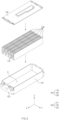
FIG. 2 is an exploded perspective view illustrating a configuration of a secondary battery module according to Embodiment 1 of the present invention. -
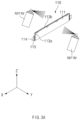
FIG. 3a is a conceptual view illustrating a state in which a secondary battery of the secondary battery module ofFIG. 2 is coated with an incombustible material. -
FIG. 3b is a conceptual view illustrating a state in which a compression pad of the secondary battery module ofFIG. 2 is coated with an incombustible material. -
FIG. 4a is a cross-sectional view illustrating a state after the secondary battery ofFIG. 3a is coated with the incombustible material. -
FIG. 4b is a cross-sectional view illustrating a state after the compression pad ofFIG. 3b is coated with the incombustible material. -
FIG. 5 is a perspective view of the secondary battery module ofFIG. 2 . -
FIG. 6 is a cross-sectional view taken along line A-A inFIG. 5 . -
FIG. 7 is a cross-sectional view taken along line B-B inFIG. 5 . - Hereinafter, preferred embodiments of the present invention will be described in detail with reference to the accompanying drawings so that those of ordinary skill in the art can easily carry out the present invention. However, the present invention may be implemented in several different forms and is not limited or restricted by the following examples.
- In order to clearly explain the present invention, detailed descriptions of portions that are irrelevant to the description or related known technologies that may unnecessarily obscure the gist of the present invention have been omitted, and in the present specification, reference symbols are added to components in each drawing. In this case, the same or similar reference numerals are assigned to the same or similar elements throughout the specification.
- Also, terms or words used in this specification and claims should not be restrictively interpreted as ordinary meanings or dictionary-based meanings, but should be interpreted as meanings and concepts conforming to the scope of the present invention on the basis of the principle that an inventor can properly define the concept of a term to describe and explain his or her invention in the best ways.
- The present invention provides a
secondary battery module 100, which further includes a plurality ofsecondary batteries 110 arranged side by side along one direction and ahousing 120 accommodating the plurality ofsecondary batteries 110, and in which at least one of thesecondary batteries 110 is coated with an incombustible material. - First, the secondary batteries may be configured to be arranged side by side along one direction inside the
housing 120 and may include an electrode assembly (not shown) and abattery case 111 accommodating the electrode assembly. The type of the electrode assembly is not limited. For example, the electrode assembly may have a structure of any one of a jelly-roll type (winding type), a stack type (stacked type), or a complex type (stack/folding type). - The electrode assembly may have a configuration in which electrodes and separators are alternately disposed. In more detail, the electrode assembly may have a configuration in which positive electrodes and negative electrodes are alternately disposed with separators therebetween. Specifically, the electrode assembly may have a structure in which positive electrode collector/positive electrode active material layer/separator/negative electrode active material layer/negative electrode collector are sequentially stacked so that the positive electrode active material layer disposed one surface of the separator faces the negative electrode active material layer disposed on the other surface of the separator.
- In order to accommodate the above-described electrode assembly, as illustrated in
FIG. 1 , thebattery case 111 may have a structure including anaccommodation part 112 accommodating the electrode assembly and anedge part 113 connected from an edge of theaccommodation part 112. - In more detail, the
battery case 111 may include theaccommodation part 112 provided by forming one region of a laminate sheet in which an inner resin layer/metal layer/outer resin layer are sequentially stacked from the inside to the outside and theedge part 113 connected to the edge of theaccommodation part 112. - Here, polypropylene (PP) may be used for the inner resin layer, polyethylene terephthalate (PET) may be used for the outer resin layer, and aluminum (Al) may be used for the metal layer. However, the materials of the inner resin layer, the outer resin layer, and the metal layer are not limited thereto, and when each of the inner resin layer and the outer resin layer has an insulating material, and the metal layer has a metal material, the materials may be used without particular limitation.
- In addition, the
accommodation part 112 may be understood as a region having an empty space by being formed concavely so that the electrode assembly is accommodated in thebattery case 111. - In addition, the
edge part 113 may be understood as a region connected from the edge of theaccommodation part 112 on thebattery case 111. Theedge part 113 may have a sealed structure, of which an edge is sealed, to prevent the electrode assembly accommodated in theaccommodation part 112 from being damaged due to exposure to external moisture or air. - In addition, the
edge part 113 may include afirst edge part 113a, from which anelectrode lead 114 to be described later protrudes, and asecond edge part 113b connected to thefirst edge part 113a and folded at least once. Preferably, thesecond edge part 113b may be double side-folded (DSF). - For example, the
first edge part 113a may be provided at both sides of thesecondary battery 110 in a full-length direction, and thesecond edge part 113b may be provided at at least one side of thesecondary battery 110 in a full-width direction. - An outer surface of the
battery case 111 may be coated with an incombustible material. - For example, the incombustible material may include a ceramic material. In this case, there is an effect of preventing insulation performance of the
secondary battery 110 from being deteriorated due to exposure of the metal layer on the outer surface of thebattery case 111. - That is, the metal layer may be exposed at an end of the
edge part 113a due to the structure of thebattery case 111, and when thebattery case 111 is manufactured, in the process of stacking the outer resin layer on the metal layer, a through-hole called a pin hole may be defined in the outer resin layer to expose the metal layer to the outside. Here, the incombustible material made of ceramic may be applied on the metal layer exposed to the outside insulate the metal layer from the outside, thereby improving insulation performance of thesecondary battery 110. - However, if necessary, the incombustible material may not be applied to an
end 113c of thesecond edge part 113b. Therefore, when a gas is generated in thesecondary battery 110 due to an abnormally high temperature or fire, the end of thesecond edge part 113b is preferentially broken to induce the gas to be discharged. Thus, the gas may be discharged to thefirst edge part 113a to prevent flame from being spread through theelectrode lead 114. - The
secondary battery 110 may include theelectrode lead 114 protruding from thebattery case 111. In addition, thesecondary battery 110 may further include an insulatingmember 115 that insulates theelectrode lead 114 from theedge part 113 of thebattery case 111, more specifically, thefirst edge part 113a. - Here, the
electrode lead 114 may be understood as a configuration that protrudes from thebattery case 111 and is electrically connected to the electrode assembly described above. In more detail, theelectrode lead 114 may have one end connected to electrode tabs (not shown) disposed on the electrode and the other end protruding out of the pouch so as to be connected to the othersecondary battery 110 or external device. - The insulating
member 115 may surround a portion of theelectrode lead 114. The insulatingmember 115 may be disposed between theedge part 113 and theelectrode lead 114. A portion of theedge part 113, more specifically, a portion of thefirst edge part 113a may be sealed with the insulatingmember 115. The insulatingmember 115 may be an insulating film or an insulating tape. A portion of the insulatingmember 115 may protrude outward from theedge part 113. - The incombustible material may not be applied to the
electrode lead 114, further more, to the insulatingmember 115. - The
secondary batteries 110 as described above may be arranged side by side along one direction, as illustrated inFIG. 2 , in order to improve energy density of thesecondary battery module 100 in the accommodation space inside thehousing 120. Here, one direction may be understood as a direction parallel to a Y-axis ofFIG. 2 . - At this time, at least one of the
secondary batteries 110 may be coated with the incombustible material on the outer surface to delay or prevent the propagation of flame or heat to othersecondary batteries 110 adjacent thereto even if onesecondary battery 110 starts to ignite. - In this case, all of the
secondary batteries 110 arranged in one direction may be coated with the incombustible material, or only some of thesecondary batteries 110 arranged in one direction may be coated with the incombustible material. In addition, it goes without saying that the entire outer surface of thesecondary battery 110 may be coated with the incombustible material, or only a portion of the outer surface may be coated with the incombustible material. - Here, the incombustible material may be any material as long as the incombustible material is capable of delaying the flame or heat propagation between the
secondary batteries 110, which are adjacent to each other, and may include, for example, a ceramic material. - In addition, the incombustible material may be applied to the
secondary battery 110 in various manners. For example, as illustrated inFIG. 3a , the incombustible material may be spray-applied to thesecondary battery 110 by a spraying device. In this case, as illustrated inFIG. 4a , anincombustible coating layer 110a may be formed on the outer surface of thesecondary battery 110. - As illustrated in
FIG. 3a , in the process of spray-applying thesecondary battery 110, a support member (not shown) such as a gripper may grip theelectrode lead 114 and/or the insulatingmember 115 to support thesecondary battery 110. As a result, the incombustible material may be entirely applied to thebattery case 111 without interfering with the support member. In addition, the incombustible material may be prevented from being applied to theelectrode lead 114 without a separate masking member. - In addition, the
incombustible coating layer 110a may be applied to thesecondary battery 110 in various thicknesses, but it may be preferable that theincombustible coating layer 110a is formed on the outer surface of thesecondary battery 110 to a thickness of 0.01 mm to 1 mm. - This is because, when the thickness of the
incombustible coating layer 110a is less than 0.01 mm, the coating of the incombustible material is not smoothly performed in the process, and an uncoated area may occur on the outer surface of thesecondary battery 110, and when the thickness exceeds 1 mm, the thickness of theincombustible coating layer 110a becomes too thick, a side effect of being separated from the outer surface of thesecondary battery 110 occurs. - The thickness of the
incombustible coating layer 110a on theedge part 113 may be thicker than the thickness of theincombustible coating layer 110a on theaccommodation part 112. That is, the thickness of the incombustible material applied to theedge part 113 may be thicker than the thickness of the incombustible material applied to theaccommodation part 112. Theedge part 113 having a sealed structure by sealing is more vulnerable to breakage than theaccommodation part 112, and thus, there is a risk that flames is preferentially emitted or invaded from theedge part 113. In order to prevent such a concern, the thickincombustible coating layer 110a is formed on theedge part 113 to delay the breakage of the sealing and also delay the propagation of the flame. - Also, the thickness of the
incombustible coating layer 110a on thefirst edge part 113a may be thicker than the thickness of thenonflammable coating layer 110a on thesecond edge part 113b. That is, the thickness of the incombustible material applied to thefirst edge part 113a may be greater than the thickness of the incombustible material applied to thesecond edge part 113b. Thefirst edge part 113a from which theelectrode lead 114 protrudes is vulnerable to the propagation of the flame, and there is a possibility that the sealing strength is relatively lower than that of thesecond edge part 113b folded at least once. In order to prevent such a concern, the thickerincombustible coating layer 110a may be formed on thefirst edge part 113a to delay the breakage of the sealing and also delay the propagation of the flame. - The
secondary battery module 100 may further include at least onecompression pad 130 disposed adjacent to thesecondary battery 110. - Here, the
compression pad 130 is disposed adjacent to thesecondary battery 110 in an accommodation space S of thehousing 120, and various configurations are possible. - Specifically, the
compression pad 130 may be made of a deformable material to prevent the module from being damaged by flexibly compensating for the space when swelling of thesecondary battery 110 occurs. For example, thecompression pad 130 may be made of a polyurethane material. - Here, the outer surface of the
compression pad 130 may also be coated with the incombustible material in order to delay or prevent the propagation of the flame or heat between thesecondary batteries 110. - Here, when the
compression pad 130 is provided in plurality, all of the plurality ofcompression pads 130 may be coated with the incombustible material, or only some of the plurality ofcompression pads 130 may be coated with the incombustible material. In addition, it goes without saying that the entire outer surface of thecompression pad 130 may be coated with the incombustible material, or only a portion of the outer surface may be coated with the incombustible material. - Here, the incombustible material may be any material as long as the incombustible material is capable of delaying the flame or heat propagation between the
secondary batteries 110, which are described above, and may include, for example, a ceramic material. - In addition, the incombustible material may be applied to the
compression pad 130 in various manners. For example, as illustrated inFIG. 3b , the incombustible material may be spray-applied to thecompression pad 130 by a spraying device. In this case, as illustrated inFIG. 4a , anincombustible coating layer 130a may be formed on the outer surface of thecompression pad 130. - In addition, the
incombustible coating layer 130a may be applied to thecompression pad 130 in various thicknesses, but it may be preferable that theincombustible coating layer 130a is formed on the outer surface of thecompression pad 130 to a thickness of 0.01 mm to 1 mm. - This is because, when the thickness of the
incombustible coating layer 130a is less than 0.01 mm, the coating of the incombustible material is not smoothly performed in the process, and an uncoated area may occur on the outer surface of thecompression pad 130, and when the thickness exceeds 1 mm, the thickness of theincombustible coating layer 130a becomes too thick, a side effect of being separated from the outer surface of thecompression pad 130 occurs. - The
compression pad 130 may have various heights and widths. - In this case, it may be preferable to form the
compression pad 130 having a height and width higher than those of the adjacentsecondary battery 110 so as to delay or prevent the flame propagation between thesecondary batteries 110 disposed with thecompression pad 130 therebetween. For example, a height H2 of thecompression pad 130 may be higher than a height H1 of thesecondary battery 110, as illustrated inFIGS. 4a to 4b (H2>H1). - The
compression pad 130 may be disposed between the plurality ofsecondary batteries 110 or between thesecondary batteries 110 and thehousing 120. Here, thecompression pad 130 may be disposed adjacent to thesecondary battery 110 coated with the incombustible material. In this case, thesecondary battery 110 and thecompression pad 130 may be disposed so that surfaces coated with the incombustible material are disposed to face each other to effectively delay the propagation of the flame or heat between thesecondary batteries 110. - The
housing 120 is configured to accommodate the plurality ofsecondary batteries 110 and/or thecompression pad 130, and various configurations are possible. - Specifically, the
housing 120 may have a structure in which the accommodation space S is defined therein to accommodate the plurality ofsecondary batteries 110 and/or thecompression pad 130. For example, thehousing 120 may include amain body 121 surrounding a portion of a surface of thesecondary battery 110 and acover part 122 connected to themain body 121 to cover the remaining surface of thesecondary battery 110. - Here, the
main body 121 may include a bottom portion (not shown) parallel to an X-Y plane ofFIG. 5 and a pair of side portions (not shown) extending from both ends of the bottom portion in an upward direction (Z direction inFIG. 5 ). In this case, themain body 121 may be formed in a '' shape to surround a portion of the surface of the
secondary battery 110. - In addition, the
cover part 122 may be connected to the side portion and be provided in a ''-shaped opening to cover the remaining surface of the
secondary battery 110. For example, thecover part 122 may be provided at an upper side of themain body 121 to cover a top surface of thesecondary battery 110. - A surface of the
main body 121 that is not covered by thecover part 122 may be covered by anend plate 123. For example, theend plate 123 may be provided at the bottom portion of themain body 121 so as to be connected to both ends on which the side surfaces are not formed, and as illustrated inFIG. 6 , theend plate 123 may be disposed on an area corresponding to theelectrode lead 114. - The
housing 120 having the above structure has at least one or more through-holes P in at least one region so that a gas generated by ignition in thesecondary battery 110 is discharged from the accommodation space S to the outside. - Here, at least one or more through-holes P may be defined in a top surface of the
housing 120 in consideration of a difference in density between the gas, which is generated in thesecondary battery 110, and air, prevention of secondary damage due to the gas discharge from thesecondary battery 110, and ease in manufacturing process. That is, when thehousing 120 has a structure including themain body 121 and thecover part 122 as described above, at least one or more through-holes P may be defined in thecover part 122. - When a gas discharge path passes through the
electrode lead 114, it is preferable that the formation direction of the through-hole P is defined at a position that does not overlap theelectrode lead 114 in consideration of an occurrence of an impact such as sparks. In this case, the through-hole P may be defined at a position facing thebattery case 111. - Even at this time, since the
accommodation part 112 on thebattery case 111 is a region in which the electrode assembly is accommodated, as illustrated inFIG. 7 , it may be more preferable that the through-hole P is defined at a position facing theedge part 113 to protect the electrode assembly from the outside. In this case, the through-hole P may be defined at a position facing theedge part 113 disposed in a width direction (Z direction inFIG. 1 ) of thesecondary battery 110. - The
secondary battery module 100 of the present invention may include a plurality ofsecondary batteries 110 arranged side by side along one direction; ahousing 120 accommodating the plurality ofsecondary batteries 110; and at least onecompression pad 130 disposed adjacent to thesecondary battery 110, and an outer surface of thecompression pad 130 is coated with an incombustible material. - Particularly, the
compression pad 130 may be coated with the incombustible material including ceramic, and a height of thecompression pad 130 may be higher than that of the adjacentsecondary battery 110. In addition, at least one or more through-holes P passing through the inside and outside of the housing may be defined in at least one area of thehousing 120. - Here, specific details related to the
secondary battery 110, thehousing 120, and thecompression pad 130 may be substituted for the above-described contents. - While the embodiments of the present invention have been described with reference to the specific embodiments, it will be apparent to those skilled in the art that various changes and modifications may be made without departing from the spirit and scope of the invention as defined in the following claims.
-
100: Secondary battery module 110: Secondary battery 110a: Incombustible coating layer 111: Battery case 112: Accommodation part 113: Edge part 113a: First edge part 113b: Second edge part 114: Electrode lead 115: Insulating member 120: Housing 121: Main body 122: Cover part 123: End plate 130: Compression pad 130a: Incombustible coating layer H1: Height of secondary battery H2: Height of compression pad S: Accommodation space P: Through-hole
Claims (20)
- A secondary battery module comprising:a plurality of secondary batteries arranged side by side along one direction; anda housing configured to accommodate the plurality of secondary batteries,wherein at least one of the plurality of secondary batteries comprises:an electrode assembly; anda battery case comprising an accommodation part in which, the electrode assembly is accommodated, and an edge part connected from the accommodation part, the battery case having an outer surface coated with an incombustible material,wherein the incombustible material applied to the edge part has a thickness greater than that of the incombustible material applied to the accommodation part.
- The secondary battery module of claim 1, wherein the edge part comprises:a first edge part from which an electrode lead connected to the electrode assembly protrudes; anda second edge part connected to the first edge part and folded at least once,wherein the incombustible material is not applied to an end of the second edge part.
- The secondary battery module of claim 1, wherein the edge part comprises:a first edge part from which an electrode lead connected to the electrode assembly protrudes; anda second edge part connected to the first edge part and folded at least once,wherein the incombustible material applied to the first edge part has a thickness greater than that of the incombustible material applied to the second edge part.
- The secondary battery module of claim 1, wherein the incombustible material is not applied to an electrode lead connected to the electrode assembly and protruded to the outside of the edge part.
- The secondary battery module of claim 4, wherein the incombustible material is not applied to an insulating member configured to insulate the electrode lead from the edge part.
- The secondary battery module of claim 1, further comprising at least one compression pad disposed adjacent to the secondary battery,
wherein an outer surface of the compression pad is coated with the incombustible material. - The secondary battery module of any one of claims 1 to 6, wherein the incombustible material comprises ceramic.
- The secondary battery module of claim 6, wherein surfaces of the secondary battery and the compression pad, which are coated with the incombustible material, are disposed to face each other.
- The secondary battery module of claim 6, wherein the compression pad has a height greater than that of the secondary battery.
- The secondary battery module of claim 1, wherein at least one or more through-holes that pass through the inside and outside of the housing are defined in at least one area of the housing.
- The secondary battery module of claim 10, wherein the at least one or more through-holes are defined in a top surface of the housing.
- The secondary battery module of claim 10, wherein the housing comprises:a main body configured to surround a portion of a surface of the secondary battery; anda cover part connected to the main body to cover a remaining portion of the surface of the secondary battery,wherein the at least one or more through-holes are defined in the cover part.
- The secondary battery module of claim 10, wherein the through-holes are defined in a position facing the battery case.
- The secondary battery module of claim 13, wherein the through-holes are defined in a position facing the edge part.
- A secondary battery comprising:an electrode assembly;a battery case comprising an accommodation part in which the electrode assembly is accommodated, and an edge part connected from the accommodation part, the battery case having an outer surface coated with an incombustible material,wherein the incombustible material applied to the edge part has a thickness greater than that of the incombustible material applied to the accommodation part.
- The secondary battery of claim 15, wherein the edge part comprises:a first edge part from which an electrode lead connected to the electrode assembly protrudes; anda second edge part connected to the first edge part and folded at least once,wherein the incombustible material is not applied to an end of the second edge part.
- The secondary battery of claim 15, wherein the edge part comprises:a first edge part from which an electrode lead connected to the electrode assembly protrudes; anda second edge part connected to the first edge part and folded at least once,wherein the incombustible material applied to the first edge part has a thickness greater than that of the incombustible material applied to the second edge part.
- The secondary battery of claim 15, wherein the incombustible material is not applied to an electrode lead connected to the electrode assembly and protruded to the outside of the edge part.
- The secondary battery of claim 18, wherein the incombustible material is not applied to an insulating member which is configured to insulate the electrode lead from the edge part and of which a portion protrudes to the outside of the edge part.
- The secondary battery of any one of claims 15 to 19, wherein the incombustible material comprises ceramic.
Applications Claiming Priority (3)
| Application Number | Priority Date | Filing Date | Title |
|---|---|---|---|
| KR20220064228 | 2022-05-25 | ||
| KR1020220153107A KR102950884B1 (en) | 2022-05-25 | 2022-11-15 | Secondary battery module and secondary battery used therein |
| PCT/KR2023/007118 WO2023229388A1 (en) | 2022-05-25 | 2023-05-25 | Secondary battery module and secondary battery used therefor |
Publications (2)
| Publication Number | Publication Date |
|---|---|
| EP4517948A1 true EP4517948A1 (en) | 2025-03-05 |
| EP4517948A4 EP4517948A4 (en) | 2025-08-06 |
Family
ID=88919750
Family Applications (1)
| Application Number | Title | Priority Date | Filing Date |
|---|---|---|---|
| EP23812162.8A Pending EP4517948A4 (en) | 2022-05-25 | 2023-05-25 | SECONDARY BATTERY MODULE AND SECONDARY BATTERY THEREFOR |
Country Status (4)
| Country | Link |
|---|---|
| EP (1) | EP4517948A4 (en) |
| JP (1) | JP7712036B2 (en) |
| CN (1) | CN119256435A (en) |
| WO (1) | WO2023229388A1 (en) |
Cited By (1)
| Publication number | Priority date | Publication date | Assignee | Title |
|---|---|---|---|---|
| EP4579911A4 (en) * | 2022-12-05 | 2026-01-21 | Lg Energy Solution Ltd | BATTERY MODULE AS WELL AS BATTERY PACK AND VEHICLE WITH IT |
Family Cites Families (11)
| Publication number | Priority date | Publication date | Assignee | Title |
|---|---|---|---|---|
| JP4766057B2 (en) | 2008-01-23 | 2011-09-07 | ソニー株式会社 | Nonaqueous electrolyte battery and method for producing nonaqueous electrolyte battery |
| KR101471666B1 (en) * | 2008-04-24 | 2014-12-10 | 주식회사 엘지화학 | Outer material for secondary battery and secondary battery including same |
| JP2011181310A (en) | 2010-03-01 | 2011-09-15 | Hitachi Maxell Energy Ltd | Lamination-type unit cell |
| KR101567632B1 (en) * | 2013-06-28 | 2015-11-09 | 현대자동차주식회사 | Temperature control apparatus and method of battery system for vehicle |
| JP6479455B2 (en) | 2014-12-19 | 2019-03-06 | 昭和電工パッケージング株式会社 | Exterior material for storage device and storage device |
| KR102157150B1 (en) * | 2015-10-19 | 2020-09-18 | 주식회사 엘지화학 | Battery Cell Comprising Inner Surface Coated with Electrical Insulating Material |
| KR102703855B1 (en) * | 2018-08-21 | 2024-09-05 | 에스케이온 주식회사 | Battery module and Manufacturing method of the same |
| KR102268897B1 (en) * | 2019-06-05 | 2021-06-25 | 에스케이씨 주식회사 | Composite sheet and battery cell module using same |
| JP2021118162A (en) | 2020-01-29 | 2021-08-10 | 積水化学工業株式会社 | Refractory resin composition, refractory material, refractory laminate, battery, back cover material, and electronic device |
| KR20230171266A (en) * | 2022-06-13 | 2023-12-20 | 에스케이온 주식회사 | Pouch type secondary battery containing fire extinguishing device |
| CN119054137A (en) * | 2022-12-02 | 2024-11-29 | 株式会社Lg新能源 | Battery module |
-
2023
- 2023-05-25 JP JP2024569147A patent/JP7712036B2/en active Active
- 2023-05-25 WO PCT/KR2023/007118 patent/WO2023229388A1/en not_active Ceased
- 2023-05-25 EP EP23812162.8A patent/EP4517948A4/en active Pending
- 2023-05-25 CN CN202380042036.3A patent/CN119256435A/en active Pending
Cited By (1)
| Publication number | Priority date | Publication date | Assignee | Title |
|---|---|---|---|---|
| EP4579911A4 (en) * | 2022-12-05 | 2026-01-21 | Lg Energy Solution Ltd | BATTERY MODULE AS WELL AS BATTERY PACK AND VEHICLE WITH IT |
Also Published As
| Publication number | Publication date |
|---|---|
| JP2025519099A (en) | 2025-06-24 |
| WO2023229388A1 (en) | 2023-11-30 |
| JP7712036B2 (en) | 2025-07-23 |
| CN119256435A (en) | 2025-01-03 |
| EP4517948A4 (en) | 2025-08-06 |
Similar Documents
| Publication | Publication Date | Title |
|---|---|---|
| EP4145610B1 (en) | Battery module and battery pack comprising same | |
| JP2023534415A (en) | Battery modules and battery packs containing the same | |
| EP4096008B1 (en) | Battery pack and device including same | |
| KR102880677B1 (en) | Battery module and, battery pack and vehicle including same | |
| EP4576341A1 (en) | Battery cell and battery module comprising same | |
| KR20240120950A (en) | Battery module comprising venting hole and battery pack comprising the same | |
| EP4531186A1 (en) | Secondary battery and secondary battery module including same | |
| KR20240014959A (en) | Battery module, batery pack and vehicle including the same | |
| CN119054137A (en) | Battery module | |
| JP7712036B2 (en) | Secondary battery module and secondary battery used therein | |
| KR102950884B1 (en) | Secondary battery module and secondary battery used therein | |
| KR20240008255A (en) | Secondary battery and secondary battery module including same | |
| JP2025538248A (en) | Battery module | |
| KR20240012303A (en) | Battery cell assembly and battery pack including the same | |
| EP4604286A1 (en) | Battery module | |
| KR20220140244A (en) | Battery pack and device including the same | |
| US20260038964A1 (en) | Secondary battery module | |
| US20250337100A1 (en) | Battery module comprising barrier and battery pack comprising the same | |
| EP4362196B1 (en) | Battery cell and battery module comprising same | |
| US20250260123A1 (en) | Battery Pack | |
| US20260038895A1 (en) | Battery module and battery pack comprising the same | |
| EP4579888A1 (en) | Secondary battery including cap plate with improved sealing ability | |
| KR20260007681A (en) | Battery cell unit including thermal propagation delay member and battery module including thermal propagation delay member and battery pack including thermal propagation delay member | |
| KR20240018353A (en) | Secondary battery module | |
| KR20250031323A (en) | Battery module comprising venting member and battery pack comprising the same |
Legal Events
| Date | Code | Title | Description |
|---|---|---|---|
| STAA | Information on the status of an ep patent application or granted ep patent |
Free format text: STATUS: THE INTERNATIONAL PUBLICATION HAS BEEN MADE |
|
| PUAI | Public reference made under article 153(3) epc to a published international application that has entered the european phase |
Free format text: ORIGINAL CODE: 0009012 |
|
| STAA | Information on the status of an ep patent application or granted ep patent |
Free format text: STATUS: REQUEST FOR EXAMINATION WAS MADE |
|
| 17P | Request for examination filed |
Effective date: 20241129 |
|
| AK | Designated contracting states |
Kind code of ref document: A1 Designated state(s): AL AT BE BG CH CY CZ DE DK EE ES FI FR GB GR HR HU IE IS IT LI LT LU LV MC ME MK MT NL NO PL PT RO RS SE SI SK SM TR |
|
| A4 | Supplementary search report drawn up and despatched |
Effective date: 20250709 |
|
| RIC1 | Information provided on ipc code assigned before grant |
Ipc: H01M 50/124 20210101AFI20250703BHEP Ipc: H01M 50/143 20210101ALI20250703BHEP Ipc: H01M 50/117 20210101ALI20250703BHEP Ipc: H01M 50/178 20210101ALI20250703BHEP Ipc: H01M 50/19 20210101ALI20250703BHEP Ipc: H01M 50/211 20210101ALI20250703BHEP Ipc: H01M 50/24 20210101ALI20250703BHEP Ipc: H01M 50/367 20210101ALI20250703BHEP Ipc: H01M 10/04 20060101ALI20250703BHEP |
|
| DAV | Request for validation of the european patent (deleted) | ||
| DAX | Request for extension of the european patent (deleted) |