EP4517943A2 - Battery cell and manufacturing method of the same - Google Patents
Battery cell and manufacturing method of the same Download PDFInfo
- Publication number
- EP4517943A2 EP4517943A2 EP24195742.2A EP24195742A EP4517943A2 EP 4517943 A2 EP4517943 A2 EP 4517943A2 EP 24195742 A EP24195742 A EP 24195742A EP 4517943 A2 EP4517943 A2 EP 4517943A2
- Authority
- EP
- European Patent Office
- Prior art keywords
- electrode assembly
- electrode
- lead
- accommodating
- lead portion
- Prior art date
- Legal status (The legal status is an assumption and is not a legal conclusion. Google has not performed a legal analysis and makes no representation as to the accuracy of the status listed.)
- Pending
Links
Images


Classifications
-
- H—ELECTRICITY
- H01—ELECTRIC ELEMENTS
- H01M—PROCESSES OR MEANS, e.g. BATTERIES, FOR THE DIRECT CONVERSION OF CHEMICAL ENERGY INTO ELECTRICAL ENERGY
- H01M50/00—Constructional details or processes of manufacture of the non-active parts of electrochemical cells other than fuel cells, e.g. hybrid cells
- H01M50/10—Primary casings; Jackets or wrappings
- H01M50/102—Primary casings; Jackets or wrappings characterised by their shape or physical structure
- H01M50/103—Primary casings; Jackets or wrappings characterised by their shape or physical structure prismatic or rectangular
-
- H—ELECTRICITY
- H01—ELECTRIC ELEMENTS
- H01M—PROCESSES OR MEANS, e.g. BATTERIES, FOR THE DIRECT CONVERSION OF CHEMICAL ENERGY INTO ELECTRICAL ENERGY
- H01M50/00—Constructional details or processes of manufacture of the non-active parts of electrochemical cells other than fuel cells, e.g. hybrid cells
- H01M50/50—Current conducting connections for cells or batteries
- H01M50/572—Means for preventing undesired use or discharge
- H01M50/584—Means for preventing undesired use or discharge for preventing incorrect connections inside or outside the batteries
- H01M50/59—Means for preventing undesired use or discharge for preventing incorrect connections inside or outside the batteries characterised by the protection means
- H01M50/593—Spacers; Insulating plates
-
- H—ELECTRICITY
- H01—ELECTRIC ELEMENTS
- H01M—PROCESSES OR MEANS, e.g. BATTERIES, FOR THE DIRECT CONVERSION OF CHEMICAL ENERGY INTO ELECTRICAL ENERGY
- H01M10/00—Secondary cells; Manufacture thereof
- H01M10/05—Accumulators with non-aqueous electrolyte
- H01M10/058—Construction or manufacture
-
- H—ELECTRICITY
- H01—ELECTRIC ELEMENTS
- H01M—PROCESSES OR MEANS, e.g. BATTERIES, FOR THE DIRECT CONVERSION OF CHEMICAL ENERGY INTO ELECTRICAL ENERGY
- H01M50/00—Constructional details or processes of manufacture of the non-active parts of electrochemical cells other than fuel cells, e.g. hybrid cells
- H01M50/10—Primary casings; Jackets or wrappings
- H01M50/172—Arrangements of electric connectors penetrating the casing
- H01M50/174—Arrangements of electric connectors penetrating the casing adapted for the shape of the cells
- H01M50/176—Arrangements of electric connectors penetrating the casing adapted for the shape of the cells for prismatic or rectangular cells
-
- H—ELECTRICITY
- H01—ELECTRIC ELEMENTS
- H01M—PROCESSES OR MEANS, e.g. BATTERIES, FOR THE DIRECT CONVERSION OF CHEMICAL ENERGY INTO ELECTRICAL ENERGY
- H01M50/00—Constructional details or processes of manufacture of the non-active parts of electrochemical cells other than fuel cells, e.g. hybrid cells
- H01M50/50—Current conducting connections for cells or batteries
- H01M50/543—Terminals
- H01M50/547—Terminals characterised by the disposition of the terminals on the cells
- H01M50/55—Terminals characterised by the disposition of the terminals on the cells on the same side of the cell
-
- H—ELECTRICITY
- H01—ELECTRIC ELEMENTS
- H01M—PROCESSES OR MEANS, e.g. BATTERIES, FOR THE DIRECT CONVERSION OF CHEMICAL ENERGY INTO ELECTRICAL ENERGY
- H01M50/00—Constructional details or processes of manufacture of the non-active parts of electrochemical cells other than fuel cells, e.g. hybrid cells
- H01M50/50—Current conducting connections for cells or batteries
- H01M50/543—Terminals
- H01M50/552—Terminals characterised by their shape
- H01M50/553—Terminals adapted for prismatic, pouch or rectangular cells
-
- H—ELECTRICITY
- H01—ELECTRIC ELEMENTS
- H01M—PROCESSES OR MEANS, e.g. BATTERIES, FOR THE DIRECT CONVERSION OF CHEMICAL ENERGY INTO ELECTRICAL ENERGY
- H01M50/00—Constructional details or processes of manufacture of the non-active parts of electrochemical cells other than fuel cells, e.g. hybrid cells
- H01M50/50—Current conducting connections for cells or batteries
- H01M50/572—Means for preventing undesired use or discharge
- H01M50/584—Means for preventing undesired use or discharge for preventing incorrect connections inside or outside the batteries
- H01M50/586—Means for preventing undesired use or discharge for preventing incorrect connections inside or outside the batteries inside the batteries, e.g. incorrect connections of electrodes
-
- H—ELECTRICITY
- H01—ELECTRIC ELEMENTS
- H01M—PROCESSES OR MEANS, e.g. BATTERIES, FOR THE DIRECT CONVERSION OF CHEMICAL ENERGY INTO ELECTRICAL ENERGY
- H01M50/00—Constructional details or processes of manufacture of the non-active parts of electrochemical cells other than fuel cells, e.g. hybrid cells
- H01M50/50—Current conducting connections for cells or batteries
- H01M50/572—Means for preventing undesired use or discharge
- H01M50/584—Means for preventing undesired use or discharge for preventing incorrect connections inside or outside the batteries
- H01M50/59—Means for preventing undesired use or discharge for preventing incorrect connections inside or outside the batteries characterised by the protection means
- H01M50/591—Covers
-
- H—ELECTRICITY
- H01—ELECTRIC ELEMENTS
- H01M—PROCESSES OR MEANS, e.g. BATTERIES, FOR THE DIRECT CONVERSION OF CHEMICAL ENERGY INTO ELECTRICAL ENERGY
- H01M50/00—Constructional details or processes of manufacture of the non-active parts of electrochemical cells other than fuel cells, e.g. hybrid cells
- H01M50/60—Arrangements or processes for filling or topping-up with liquids; Arrangements or processes for draining liquids from casings
- H01M50/609—Arrangements or processes for filling with liquid, e.g. electrolytes
- H01M50/627—Filling ports
-
- H—ELECTRICITY
- H01—ELECTRIC ELEMENTS
- H01M—PROCESSES OR MEANS, e.g. BATTERIES, FOR THE DIRECT CONVERSION OF CHEMICAL ENERGY INTO ELECTRICAL ENERGY
- H01M50/00—Constructional details or processes of manufacture of the non-active parts of electrochemical cells other than fuel cells, e.g. hybrid cells
- H01M50/10—Primary casings; Jackets or wrappings
- H01M50/147—Lids or covers
- H01M50/148—Lids or covers characterised by their shape
- H01M50/15—Lids or covers characterised by their shape for prismatic or rectangular cells
-
- Y—GENERAL TAGGING OF NEW TECHNOLOGICAL DEVELOPMENTS; GENERAL TAGGING OF CROSS-SECTIONAL TECHNOLOGIES SPANNING OVER SEVERAL SECTIONS OF THE IPC; TECHNICAL SUBJECTS COVERED BY FORMER USPC CROSS-REFERENCE ART COLLECTIONS [XRACs] AND DIGESTS
- Y02—TECHNOLOGIES OR APPLICATIONS FOR MITIGATION OR ADAPTATION AGAINST CLIMATE CHANGE
- Y02E—REDUCTION OF GREENHOUSE GAS [GHG] EMISSIONS, RELATED TO ENERGY GENERATION, TRANSMISSION OR DISTRIBUTION
- Y02E60/00—Enabling technologies; Technologies with a potential or indirect contribution to GHG emissions mitigation
- Y02E60/10—Energy storage using batteries
-
- Y—GENERAL TAGGING OF NEW TECHNOLOGICAL DEVELOPMENTS; GENERAL TAGGING OF CROSS-SECTIONAL TECHNOLOGIES SPANNING OVER SEVERAL SECTIONS OF THE IPC; TECHNICAL SUBJECTS COVERED BY FORMER USPC CROSS-REFERENCE ART COLLECTIONS [XRACs] AND DIGESTS
- Y02—TECHNOLOGIES OR APPLICATIONS FOR MITIGATION OR ADAPTATION AGAINST CLIMATE CHANGE
- Y02P—CLIMATE CHANGE MITIGATION TECHNOLOGIES IN THE PRODUCTION OR PROCESSING OF GOODS
- Y02P70/00—Climate change mitigation technologies in the production process for final industrial or consumer products
- Y02P70/50—Manufacturing or production processes characterised by the final manufactured product
Definitions
- the present disclosure relates to a battery cell and a manufacturing method of the same.
- a secondary battery is a battery that is made to convert electrical energy into chemical energy and store it so that it may be reused multiple times through charging and discharging.
- Secondary batteries are widely used across industries due to their economical and eco-friendly characteristics.
- lithium secondary batteries are widely used throughout industries, including portable devices that require high-density energy.
- the operating principle of lithium secondary batteries is an electrochemical oxidation-reduction reaction.
- the principle is that electricity is generated through the movement of lithium ions and charged in the reverse process.
- a phenomenon in which lithium ions in an anode escape therefrom and move to a cathode through an electrolyte and a separator is referred to as discharge.
- the opposite process of this phenomenon is referred to as charging.
- An electrode assembly including a cathode and an anode may be manufactured by being accommodated in a case and then injecting an electrolyte into the case. At this time, when the electrode assembly and the case are not electrically insulated, a fire or explosion may occur due to short circuit by the case. Therefore, research is actively being conducted to efficiently insulate an electrode assembly from a case after the electrode assembly is accommodated in the case.
- a problem that the present disclosure aims to solve is to improve the stability of a battery cell by blocking the possibility of contact between an electrode assembly and a case.
- Another problem that the present disclosure aims to solve is to improve battery cell production efficiency by improving assemblability of battery cells.
- the battery cell of the present disclosure can be widely applied in the field of green technology, such as electric vehicles, battery charging stations, solar power generation, and wind power generation using batteries.
- the battery cell of the present disclosure can be used in eco-friendly electric vehicles, hybrid vehicles, etc. to prevent climate change by suppressing air pollution and greenhouse gas emissions.
- a battery cell includes: an electrode assembly including a first electrode and a second electrode having a potential different from the first electrode; an accommodating body including an opening formed by opening one surface and accommodating the electrode assembly therein; an accommodating cover coupled with the opening to cover the electrode assembly; a lead portion formed at one end of each of the first electrode and the second electrode to electrically connect the electrode assembly to the outside; a lead blocking portion positioned between the electrode assembly and the accommodating body and blocking contact between the lead portion and the accommodating body; and an insulating member covering the outside of the electrode assembly.
- the electrode assembly may include: an upper surface facing the opening; a bottom surface formed at a position opposite to the upper surface; a first surface and a second surface facing in a direction in which the lead portion protrudes between the upper surface and the bottom surface; and a third surface and a fourth surface between the first surface and the second surface.
- the lead portion may protrude from each of the first surface and the second surface.
- the lead blocking portion may be positioned between the first surface and the accommodating body and between the second surface and the accommodating body.
- the lead blocking portion may include a through-hole formed by penetrating along a direction in which the lead portion protrudes from the electrode assembly.
- the through-hole may be formed at a position corresponding to the lead portion.
- the thickness of the lead portion along the direction in which the lead portion protrudes from the electrode assembly may be greater than or equal to the length of the lead portion.
- the lead blocking portion may be formed of an insulating material.
- the insulating member may cover the third surface, the fourth surface, and the bottom surface.
- the insulating member may cover the outside of the lead blocking portion positioned on each of the first surface and the second surface.
- the insulating member may be formed of an insulating material.
- a manufacturing method of a battery cell according to the present disclosure includes: allowing the accommodating cover to cover one surface of the electrode assembly and connecting the lead portion to the accommodating cover; covering the lead portion and connecting the lead blocking portion to the accommodating cover; covering the outside of the electrode assembly with an insulating member; and inserting the electrode assembly connected to the accommodating cover into the accommodating body through the opening.
- the covering the outside of the electrode assembly with an insulating member may include: disposing an electrode assembly on an insulating member; and folding the insulating member along a direction perpendicular to the direction in which the lead portion protrudes from the electrode assembly.
- the folding the insulating member may include: folding a first region and a second region of the insulating member, each positioned on both sides of a bottom region of the insulating member in contact with the bottom surface of the electrode assembly, along a direction perpendicular to the direction in which the lead portion protrudes; folding upward a third region in the bottom region of the insulating member positioned outside the electrode assembly along a direction in which the lead portion protrudes from the electrode assembly; and folding each of a part of the first region and a part of the second region in the direction in which the lead blocking portion is positioned.
- the manufacturing method may further include injecting an electrolyte into the accommodating body through an injection hole penetrating the accommodating cover.
- the stability of a battery cell can be improved by blocking the possibility of contact between an electrode assembly and a case
- battery cell production efficiency can be improved by improving assemblability of battery cells.
- expressions such as “same” and “is the same” not only indicate a strictly identical state, but also indicate a state in which there is a difference in tolerance or the degree to which the same function is obtained.
- Each axis direction refers to both directions in which each axis extends.
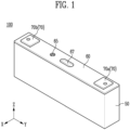
- FIG. 1 shows a battery cell 100 according to one embodiment of the present disclosure
- FIGS. 2 and 3 show an electrode assembly 20 and an accommodating cover 60 according to one embodiment of the present disclosure.
- a battery cell 100 includes: an electrode assembly 20 including a first electrode 21 and a second electrode 22 having a potential different from the first electrode 21; an accommodating body 50 including an opening 55 formed by opening one surface and accommodating the electrode assembly 20 therein; an accommodating cover 60 coupled with the opening 55 to cover the electrode assembly 20; a lead portion 25 formed at one end of each of the first electrode 21 and the second electrode 22 to electrically connect the electrode assembly 20 to the outside; a lead blocking portion 30 positioned between the electrode assembly 20 and the accommodating body 50 and blocking contact between the lead portion 25 and the accommodating body 50; and an insulating member 40 covering the outside of the electrode assembly 20.
- Battery cells 100 may be classified into a pouch-type secondary battery, a prismatic secondary battery, or a cylindrical secondary battery depending on the shape.
- a prismatic secondary battery is illustrated in the present specification as an example for convenience of explanation, but the present invention is not limited thereto.
- a battery cell 100 may include an electrode assembly 20.
- An electrode assembly 20 may include a first electrode 21 and a second electrode 22 having a potential different from the first electrode 21.
- a first electrode 21 may be a cathode and a second electrode 22 may be an anode.
- a first electrode 21 may be an anode and a second electrode 22 may be cathode.
- An electrode assembly 20 may convert chemical energy into electrical energy through a redox reaction of a first electrode 21 and a second electrode 22.
- Electrode assemblies 20 may be classified into stacking type, winding type, stack-folding type, and Z-stacking type according to the manner in which a cathode, an anode, and a separator 23 are stacked.
- a battery cell 100 of the present disclosure is not limited to any one stacking method and may include electrode assemblies 20 stacked in various manners.
- a battery cell 100 may further include a separator 23.
- a separator 23 may be positioned between a first electrode 21 and a second electrode 22 to block contact between the first electrode 21 and the second electrode 22.
- the type of a separator 23 is not particularly limited, but it may include a porous polymer film.
- a separator 23 may include a porous polymer film or a porous non-woven fabric.
- a separator 23 may be positioned between a first electrode 21 and a second electrode 22. Through this, it is possible to prevent a first electrode 21 and a second electrode 22 from contacting each other and prevent a short circuit.
- a battery cell 100 may further include an electrolyte.
- An electrolyte may be a medium that transfers ions or a current between a first electrode 21 and a second electrode 22.
- An electrolyte may be a non-aqueous electrolyte solution.
- An electrolyte solution may include a lithium salt and an organic solvent.
- a battery cell 100 may further include an accommodating housing.
- An accommodating housing may accommodate an electrode assembly 20 therein.
- an accommodating housing may further accommodate an electrolyte therein.
- a battery cell 100 may accommodate an electrode assembly 20 and an electrolyte inside an accommodating housing.
- An accommodating housing may include an accommodating body 50 and an accommodating cover 60.
- An accommodating body 50 may include an opening (55 in FIG. 7 ) formed by opening one surface and may accommodate an electrode assembly 20 therein.
- An electrode assembly 20 may be accommodated in the inside through an opening 55. The structure of an accommodating body 50 will be described in detail with reference to FIG. 7 below.
- An accommodating cover 60 may be coupled with an opening 55 of an accommodating housing to cover an electrode assembly 20.
- An accommodating cover 60 may be coupled with an opening 55 to close the opening 55. By closing an opening 55, an electrolyte and an electrode assembly 20 may be stably accommodated inside an accommodating housing.
- an accommodating cover 60 may further include an injection hole 65 and a venting portion 67.
- An electrolyte may be injected into an accommodating housing through an injection hole 65.
- an electrolyte solution may injected into the accommodating body 50 through an injection hole 65 of the accommodating cover 60.
- An injection hole 65 may be formed through an accommodating cover 60. Through this, an electrolyte may be injected from the outside of an accommodating housing to the inside of the accommodating housing.
- a venting portion 67 may control the pressure inside an accommodating housing.
- the internal pressure of an accommodating housing may increase.
- a battery cell 100 may explode, so it is necessary to control the internal pressure.
- a venting portion 67 may be opened when the pressure inside an accommodating housing rises above a preset condition.
- a venting portion 67 may be opened to form a passage through which a gas may move.
- a gas may be discharged from the inside of an accommodating housing to the outside of an accommodating housing through a passage.
- the venting portion 67 may be a notch.
- a battery cell 100 includes a lead portion 25 formed at one end of each of a first electrode 21 and a second electrode 22 to electrically connect an electrode assembly 20 to the outside.
- a lead portion 25 may be formed at one end of a first electrode 21. In addition, a lead portion 25 may be formed at one end of a second electrode 22. A lead portion 25 may include a first lead portion 251 formed at one end of a first electrode 21 and a second lead portion 252 formed at one end of a second electrode 22.
- first lead portion 251 may electrically connect the cathode to the outside, and a second lead portion 252 may electrically connect the anode to the outside.
- a first electrode 21 and a second electrode 22 may each include a current collector.
- a current collector may include any known conductive material as long as it does not cause a chemical reaction within a battery cell 100.
- a current collector may include any one of stainless steel, nickel (Ni), aluminum (Al), titanium (Ti), copper (Cu), and alloys thereof, and may be provided in various forms such as films, sheets, and foils.
- a current collector used in a first electrode 21 may be made of aluminum
- a current collector used in a second electrode 22 may be made of copper.
- a first electrode 21 and a second electrode 22 each may further include an active material, and an active material may be applied on a current collector.
- An active material may be a material which lithium ions may be inserted to and extracted from.
- an active material used in a first electrode 21 may be an lithium metal oxide
- an active material used in a second electrode 22 may be any one of a carbon-based material such as crystalline carbon, amorphous carbon, carbon composite, and carbon fiber, a lithium alloy, silicon (Si), and tin (Sn).
- a current collector of a first electrode 21 may include a region where an active material is applied and a region where an active material is not applied. A region on a current collector of a first electrode 21 where an active material is not applied may be referred to as an uncoated portion.
- a lead portion 25 may include an uncoated portion.
- a battery cell 100 may include a plurality of electrodes.
- a plurality of first electrodes 21 and a plurality of second electrodes 22 may be stacked.
- Each of a plurality of first electrodes 21 may include an uncoated portion.
- each of the plurality of second electrodes 22 may include an uncoated portion.
- a lead portion 25 may include uncoated portions of a plurality of first electrodes 21.
- the uncoated portions of the plurality of first electrodes 21 may be connected to each other to form a first lead portion 251.
- a first lead portion 251 may electrically connect a plurality of first electrodes 21 to the outside.
- a lead portion 25 may include uncoated portions of a plurality of second electrodes 22.
- the uncoated portions of the plurality of second electrodes 22 may be connected to each other to form a second lead portion 252.
- a second lead portion 252 may electrically connect a plurality of second electrodes 22 to the outside.
- a first lead portion 251 may be formed to protrude from one side of an electrode assembly 20 along the Y-axis direction.
- a second lead portion 252 is not illustrated in the drawings, it may be formed on the opposite side of a first lead portion 251 along the Y-axis direction.
- a battery cell 100 may further include a current collecting plate 80.
- a current collecting plate 80 may electrically connect a tab portion 70 and a lead portion 25.
- a tab portion 70 may be formed on the outside of an accommodating housing and connected to an external device.
- a tab portion 70 may include a first tab portion 70a connected to a first electrode 21 and a second tab portion 70b connected to an anode. More specifically, a first tab portion 70a may be connected to a first lead portion 251. A second tab portion 70b may be connected to a second lead portion 252.
- a current collecting plate 80 may be in contact with each of a lead portion 25 and a tab portion 70 and may electrically connect each other. To this end, a current collecting plate 80 may be formed of an electrically conductive material.
- a first tab portion 70a and a second tab portion 70b may each be formed at an accommodating cover 60.
- a current collector plate 80 may be in contact with each of lead portions 25.
- a first electrode 21 and a second electrode 22 may be electrically connected to a first tab portion 70a and a second tab portion 70b, respectively.
- An electrode assembly 20 may include: an upper surface 260 facing the opening 55; a bottom surface 250 formed at a position opposite to the upper surface 260; a first surface 210 and a second surface 220 facing in a direction in which the lead portion 25 protrudes between the upper surface 260 and the bottom surface 250; and a third surface 230 and a fourth surface 240 between the first surface 210 and the second surface 220.
- An electrode assembly 20 may include an upper surface 260 that faces an opening 55 and is covered by an accommodating cover 60.
- an electrode assembly 20 may include a bottom surface 250 formed at a position opposite to an upper surface 260 to form a bottom.
- An upper surface 260 and a bottom surface 250 may be formed to be parallel to each other.
- an upper surface 260 may refer to a surface of an electrode assembly 20 facing the +Z-axis direction
- a bottom surface 250 may refer to a surface of the electrode assembly 20 facing the -Z-axis direction.
- a first surface 210, a second surface 220, a third surface 230, and a fourth surface 240 may be formed between an upper surface 260 and a bottom surface 250.
- a first surface 210, a second surface 220, a third surface 230, and a fourth surface 240 may be formed in a direction perpendicular to an upper surface 260 and a bottom surface 250.
- a first surface 210, a second surface 220, a third surface 230, and a fourth surface 240 may be formed in directions perpendicular to each other.
- a lead portion 25 may be formed at one end of each of a first electrode 21 and a second electrode 22.
- the lead portion 25 may protrude from each of the first surface 210 and the second surface 220.
- a first lead portion 251 may be formed at one end of a first electrode 21 and may be formed to protrude from a first surface 210 of the electrode assembly 20.
- a second lead portion 252 may be formed at one end of a second electrode 22 and may be formed to protrude from a second surface 220 of the electrode assembly 20.
- a first surface 210 and a second surface 220 may refer to opposing surfaces of an electrode assembly 20 on which a lead portion 25 is formed.
- a third surface 230 and a fourth surface 240 may be formed between a first surface 210 and a second surface 220.
- a third side 230 and a fourth side 240 may be formed to be parallel to each other.
- a third side 230 and a fourth side 240 may refer to opposite surfaces of an electrode assembly 20.
- a third surface 230 may refer to a surface of an electrode assembly 20 facing the +X-axis direction
- a fourth surface 240 may refer to a surface of the electrode assembly 20 facing the -X-axis direction.
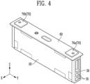
- FIG. 4 shows a lead blocking portion 30 coupled with an electrode assembly 20 according to one embodiment of the present disclosure
- FIG. 5 shows a front view of an electrode assembly 20 according to one embodiment of the present disclosure
- FIG. 6 shows a side view of an electrode assembly 20 according to one embodiment of the present disclosure.
- a lead blocking portion 30 may be positioned between an electrode assembly 20 and an accommodating body 50 and may block contact between a lead portion 25 and an accommodating body 50.
- the accommodating body 50 and the lead portion 25 may be electrically connected.
- an accommodating body 50 is made of aluminum, it may contact a lead portion 25 so that the accommodating body 50 and the lead portion 25 may be electrically connected.
- a lead blocking portion 30 may be positioned between an electrode assembly 20 and a lead portion 25.
- a lead blocking portion 30 may be positioned between an accommodating body 50 and a surface where a lead portion 25 protrudes from an electrode assembly 20.
- a lead portion 25 may protrude to the outside of an electrode assembly 20 each on a first surface 210 and a second surface 220.
- a lead blocking portion 30 may be positioned between a first surface 210 and an accommodating body 50 and between a second surface 220 and an accommodating body 50.
- a lead blocking portion 30 may be formed of an insulating material.
- a lead blocking portion 30 may be made of rubber, but is not limited thereto.
- a lead blocking portion 30 may be coupled with a first surface 210 of an electrode assembly 20.
- a lead blocking portion 30 may be coupled with a second surface 220 of an electrode assembly 20.
- a lead blocking portion 30 may be coupled with an accommodating cover 60.
- One end of a lead blocking portion 30 may be coupled with an accommodating cover 60, so that the position of the lead blocking portion 30 may be fixed, and a lead portion 25 may be stably protected.
- the lead blocking portion 30 may include a through-hole 35 formed by penetrating along a direction in which the lead portion 25 protrudes from the electrode assembly 20.
- a lead blocking portion 30 When a lead blocking portion 30 covers an electrode assembly 20, the shape of a lead portion 25 needs to be considered. Since a lead portion 25 protrudes, when a lead blocking portion 30 is formed to be flat, the lead blocking portion 30 will protrude in a shape corresponding to the lead portion 25. In this case, the space inside an accommodating housing may not be used efficiently, so the energy density of a battery cell 100 will decrease. In addition, the structural stability of a battery cell 100 may also be reduced.
- a lead blocking portion 30 of the present disclosure may include a through-hole 35, and so one end of a lead portion 25 may be inserted into the through-hole 35. In other words, even when a lead portion 25 is inserted into a through-hole 35 and a lead blocking portion 30 is coupled with an electrode assembly 20, the outer surface of a lead blocking portion 30 may not protrude.
- a through-hole 35 may be formed at a position corresponding to a lead portion 25. Through this, one end of a lead portion 25 may be inserted into a through-hole 35.
- the thickness of a lead portion 25 along the direction in which the lead portion 25 protrudes from an electrode assembly may be greater than or equal to the length of the lead portion 25. In other words, one end of a lead portion 25 inserted into a through-hole 35 will not protrude to the outside of a lead blocking portion 30.
- a lead portion 25 may include a through-hole 35.
- a through-hole 35 may be formed by penetrating a lead blocking portion 30 in a direction parallel to the direction in which a lead portion 25 protrudes from an electrode assembly 20.
- a through-hole 35 is formed by penetrating a lead blocking portion 30 along the Y-axis direction, and one end of a lead portion 25 may be inserted into the through-hole 35.
- one end of the lead portion 25 may not protrude to the outside of the lead blocking portion 30.
- a lead portion 25 may not protrude to the outside of a lead blocking portion 30 along the Y-axis direction.
- an electrolyte may move through a through-hole 35.
- an electrolyte may be an electrolyte solution. After an electrode assembly 20 is accommodated in an accommodating body 50, an electrolyte may be injected into the accommodating body 50. An electrolyte may fill up from the bottom of an accommodating body 50 and immerse an electrode assembly 20.
- An electrolyte may move from the outside of an electrode assembly 20 toward the inside along a first electrode 21, a second electrode 22, and a separator 23. Meanwhile, an electrolyte moving along a first electrode 21, a second electrode 22, and a separator 23 will move at a slow speed.
- an electrolyte may move through a through-hole 35 of a lead blocking portion 30. Through this, an electrolyte may be delivered at a high speed to the center of an electrode assembly 20.
- a through-hole 35 may be formed at a position corresponding to a lead portion 25.
- a lead portion 25 may be exposed to the outside through a through-hole 35.
- an electrolyte may move through a through-hole 35.
- a through-hole 35 may extend along the height direction of an electrode assembly 20.
- through-holes 35 may be provided in a plural number.
- the number of through-holes 35 is not particularly limited as long as a lead portion 25 may be inserted and an electrolyte may move therethrough.
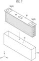
- FIG. 7 shows inserting an electrode assembly 20 into an accommodating body 50 according to one embodiment of the present disclosure.
- a battery cell 100 of the present disclosure includes an insulating member 40 covering the outside of an electrode assembly 20.
- An insulating member 40 may prevent contact between an electrode assembly 20 and an accommodating housing. Through this, the electrical stability of an electrode assembly 20 may be improved.
- an opening 55 may be formed to be open on one side of an accommodating body 50.
- An electrode assembly 20 may be accommodated in an accommodating body 50 through an opening 55. Meanwhile, an electrode assembly 20 may be accommodated in an accommodating body 50 while the electrode assembly is connected to an accommodating cover 60. Therefore, an electrode assembly 20 may be inserted into an accommodating body 50, and an accommodating cover 60 and the accommodating body 50 may be coupled.
- An insulating member 40 may be formed of an insulating material.
- an insulating member 40 may include at least one from the group consisting of polyethylene terephthalate (PET), polyimide (PI), and polypropylene (PP).
- PET polyethylene terephthalate
- PI polyimide
- PP polypropylene
- an insulating member 40 may include a known insulating material.
- an insulating member 40 may have adhesiveness.
- an insulating member 40 may be an insulating tape.
- An insulating member 40 may be easily and stably attached to an electrode assembly 20 while surrounding the outside of the electrode assembly 20.
- an insulating member 40 may cover a third surface 230 and a fourth surface 240 of an electrode assembly 20 to block an electrode assembly 20 from contacting an accommodating housing.
- an insulating member 40 may cover a bottom surface 250 of an electrode assembly 20.
- an insulating member 40 may cover the third surface 230, the fourth surface 240, and the bottom surface 250. Through this, an insulating member 40 may prevent an electrode assembly 20 from being electrically connected to an accommodating housing.
- an insulating member 40 may cover the outside of a lead blocking portion 30.
- An insulating member 40 may cover the outside of a lead blocking portion 30 each positioned on a first surface 210 and a second surface 220.
- an insulating member 40 of the present disclosure may cover a third side 230, a fourth side 240, and a bottom surface 250 and may cover the outside of a lead blocking portion 30 each positioned on a first side 210 and a second side 220.
- FIG. 8 shows an insulating member 40 according to one embodiment of the present disclosure.
- An insulating material covering the outside of an electrode assembly 20 may be formed integrally. For example, when an insulating material is unfolded, the insulating material may be formed into a rectangular shape. The outside of an electrode assembly may be covered by folding a rectangular insulating material.
- each region of the insulating member 40 may be folded to cover the outside of the electrode assembly 20. Through this, the manufacturing process may be simplified, and the manufacturing costs may be reduced.
- An insulating member 40 may include a bottom region 405 in contact with a bottom surface 250 of an electrode assembly 20, and a first region 410 and a second region 420 each positioned on both sides of the bottom region 405.
- a bottom region 405 may be positioned between a first region 410 and a second region 420.
- a bottom region 405 may be formed at the center along the direction in which an insulating member 40 extends.
- a first region 410 and a second region 420 may be formed on both sides of a bottom region 405 along the direction in which an insulating member 40 extends.
- an insulating member 40 may extend along the X-axis direction.
- a bottom region 405 may be formed at the center of at insulating member 40, and a first region 410 and a second region 420 may each be formed on both sides.
- an insulating member 40 may further include a third region 407.
- a third region 407 may be a part of a bottom region 405.
- a third region 407 may be a region of the bottom region 405 positioned outside ah electrode assembly 20 along the direction in which a lead portion 25 protrudes from an electrode assembly 20.
- An electrode assembly 20 may be in contact with a part of a bottom region 405. At this time, a lead portion 25 may protrude along the Y-axis direction, and a part of the bottom region 405 positioned on the outside of the electrode assembly 20 along the direction in which the lead portion 25 protrudes may be a third region 407.
- a lead portion 25 may protrude along the Y-axis direction, and a third region 407 may be formed outside a bottom region 405.
- a third region 407 may be folded upward and attached to a lead blocking portion 30.
- FIGS. 9 and 10 show flowcharts of a manufacturing method of a battery cell 100 according to one embodiment of the present disclosure
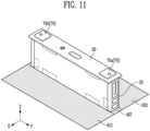
- FIGS. 11 to 13 schematically show an insulating member 40 covering an electrode assembly 20 according to one embodiment of the present disclosure.
- the manufacturing method of the battery cell 100 of the present disclosure includes: allowing the accommodating cover 60 to cover one surface of the electrode assembly 20 and connecting the lead portion 25 to the accommodating cover 60 (S10); covering the lead portion 25 and connecting the lead blocking portion 30 to the accommodating cover 60 (S30); covering the outside of the electrode assembly 20 with an insulating member 40 (S50); and inserting the electrode assembly 20 connected to the accommodating cover 60 into the accommodating body 50 through the opening 55 (S70).
- the covering the outside of the electrode assembly 20 with an insulating member 40 may include: disposing an electrode assembly 20 on an insulating member 40 (S51); and folding the insulating member 40 along a direction perpendicular to the direction in which the lead portion 25 protrudes from the electrode assembly 20 (S53).
- the folding the insulating member 40 may include: folding a first region 410 and a second region 420 of the insulating member 40, each positioned on both sides of a bottom region 405 of the insulating member 40 in contact with the bottom surface 250 of the electrode assembly 20, along a direction perpendicular to the direction in which the lead portion 25 protrudes (S531); folding upward a third region 407 in the bottom region 405 of the insulating member 40 positioned outside the electrode assembly 20 along a direction in which the lead portion 25 protrudes from the electrode assembly 20 (S533); and folding each of a part of the first region 410 and a part of the second region 420 in the direction in which the lead blocking portion 30 is positioned (S535).
- folding a first region 410 and a second region 420 may be first carried out.
- a first region 410 and a second region 420 may be folded in a direction perpendicular to the direction in which a lead portion 25 protrudes.
- a first region 410 and a second region 420 may fold an insulating member 40 along a direction perpendicular to the direction in which a lead portion 25 protrudes.
- a first region 410 and a second region 420 may be folded along the X-axis direction.
- a first region 410 may cover a third surface 230
- a second region 420 may cover a fourth surface 240.
- folding each of a part of a first region 410 and a part of a second region 420 in the direction in which a lead blocking portion 30 is positioned may be carried out.
- an insulating member 40 may cover the outside of a lead blocking portion 30 and the outside of an electrode assembly 20.
- an electrode assembly 20 after covering the outside of an electrode assembly 20 with an insulating member 40 (S50), inserting an electrode assembly 20 into an accommodating body 50 through an opening 55 (S70) may be carried out.
- An electrode assembly 20 may be inserted into an accommodating body 50, and an accommodating cover 60 and the accommodating body 50 may be coupled.
- the present disclosure may further include injecting an electrolyte solution into the accommodating body 50 through an injection hole 65 penetrating the accommodating cover 60 (S90).
- An electrolyte solution may be injected into an accommodating body 50 through an injection hole 65.
- An electrode assembly 20 may be immersed in an electrolyte solution accommodated in the accommodating body 50.
Landscapes
- Chemical & Material Sciences (AREA)
- Chemical Kinetics & Catalysis (AREA)
- Electrochemistry (AREA)
- General Chemical & Material Sciences (AREA)
- Engineering & Computer Science (AREA)
- Manufacturing & Machinery (AREA)
- Secondary Cells (AREA)
- Connection Of Batteries Or Terminals (AREA)
Abstract
Description
- The present disclosure relates to a battery cell and a manufacturing method of the same.
- A secondary battery is a battery that is made to convert electrical energy into chemical energy and store it so that it may be reused multiple times through charging and discharging. Secondary batteries are widely used across industries due to their economical and eco-friendly characteristics. In particular, among secondary batteries, lithium secondary batteries are widely used throughout industries, including portable devices that require high-density energy.
- The operating principle of lithium secondary batteries is an electrochemical oxidation-reduction reaction. In other words, the principle is that electricity is generated through the movement of lithium ions and charged in the reverse process. In the case of a lithium secondary battery, a phenomenon in which lithium ions in an anode escape therefrom and move to a cathode through an electrolyte and a separator is referred to as discharge. In addition, the opposite process of this phenomenon is referred to as charging.
- An electrode assembly including a cathode and an anode may be manufactured by being accommodated in a case and then injecting an electrolyte into the case. At this time, when the electrode assembly and the case are not electrically insulated, a fire or explosion may occur due to short circuit by the case. Therefore, research is actively being conducted to efficiently insulate an electrode assembly from a case after the electrode assembly is accommodated in the case.
- A problem that the present disclosure aims to solve is to improve the stability of a battery cell by blocking the possibility of contact between an electrode assembly and a case.
- In addition, another problem that the present disclosure aims to solve is to improve battery cell production efficiency by improving assemblability of battery cells.
- In addition, the battery cell of the present disclosure can be widely applied in the field of green technology, such as electric vehicles, battery charging stations, solar power generation, and wind power generation using batteries.
- In addition, the battery cell of the present disclosure can be used in eco-friendly electric vehicles, hybrid vehicles, etc. to prevent climate change by suppressing air pollution and greenhouse gas emissions.
- A battery cell according to the present disclosure includes: an electrode assembly including a first electrode and a second electrode having a potential different from the first electrode; an accommodating body including an opening formed by opening one surface and accommodating the electrode assembly therein; an accommodating cover coupled with the opening to cover the electrode assembly; a lead portion formed at one end of each of the first electrode and the second electrode to electrically connect the electrode assembly to the outside; a lead blocking portion positioned between the electrode assembly and the accommodating body and blocking contact between the lead portion and the accommodating body; and an insulating member covering the outside of the electrode assembly.
- The electrode assembly may include: an upper surface facing the opening; a bottom surface formed at a position opposite to the upper surface; a first surface and a second surface facing in a direction in which the lead portion protrudes between the upper surface and the bottom surface; and a third surface and a fourth surface between the first surface and the second surface.
- The lead portion may protrude from each of the first surface and the second surface.
- The lead blocking portion may be positioned between the first surface and the accommodating body and between the second surface and the accommodating body.
- The lead blocking portion may include a through-hole formed by penetrating along a direction in which the lead portion protrudes from the electrode assembly.
- The through-hole may be formed at a position corresponding to the lead portion.
- The thickness of the lead portion along the direction in which the lead portion protrudes from the electrode assembly may be greater than or equal to the length of the lead portion.
- The lead blocking portion may be formed of an insulating material.
- The insulating member may cover the third surface, the fourth surface, and the bottom surface.
- The insulating member may cover the outside of the lead blocking portion positioned on each of the first surface and the second surface.
- The insulating member may be formed of an insulating material.
- A manufacturing method of a battery cell according to the present disclosure includes: allowing the accommodating cover to cover one surface of the electrode assembly and connecting the lead portion to the accommodating cover; covering the lead portion and connecting the lead blocking portion to the accommodating cover; covering the outside of the electrode assembly with an insulating member; and inserting the electrode assembly connected to the accommodating cover into the accommodating body through the opening.
- The covering the outside of the electrode assembly with an insulating member may include: disposing an electrode assembly on an insulating member; and folding the insulating member along a direction perpendicular to the direction in which the lead portion protrudes from the electrode assembly.
- The folding the insulating member may include: folding a first region and a second region of the insulating member, each positioned on both sides of a bottom region of the insulating member in contact with the bottom surface of the electrode assembly, along a direction perpendicular to the direction in which the lead portion protrudes; folding upward a third region in the bottom region of the insulating member positioned outside the electrode assembly along a direction in which the lead portion protrudes from the electrode assembly; and folding each of a part of the first region and a part of the second region in the direction in which the lead blocking portion is positioned.
- The manufacturing method may further include injecting an electrolyte into the accommodating body through an injection hole penetrating the accommodating cover.
- According to one embodiment of the present disclosure, the stability of a battery cell can be improved by blocking the possibility of contact between an electrode assembly and a case
- In addition, battery cell production efficiency can be improved by improving assemblability of battery cells.
-
-
FIG. 1 shows a battery cell according to one embodiment of the present disclosure. -
FIGS. 2 and3 show an electrode assembly and an accommodating cover according to one embodiment of the present disclosure. -
FIG. 4 shows a lead blocking portion coupled with an electrode assembly according to one embodiment of the present disclosure. -
FIG. 5 shows a front view of an electrode assembly according to one embodiment of the present disclosure. -
FIG. 6 shows a side view of an electrode assembly according to one embodiment of the present disclosure. -
FIG. 7 shows inserting an electrode assembly into an accommodating body according to one embodiment of the present disclosure. -
FIG. 8 shows an insulating member according to one embodiment of the present disclosure. -
FIGS. 9 and10 show flowcharts of a manufacturing method of a battery cell according to one embodiment of the present disclosure. -
FIGS. 11 to 13 schematically show an insulating member covering an electrode assembly according to one embodiment of the present disclosure. - Hereinafter, the present disclosure will be described in detail with reference to the attached drawings. However, this is merely illustrative, and the present disclosure is not limited to the specific embodiments described in an illustrative manner.
- Specific terms used in the present specification are merely for convenience of explanation and are not used to limit the illustrated embodiments.
- For example, expressions such as "same" and "is the same" not only indicate a strictly identical state, but also indicate a state in which there is a difference in tolerance or the degree to which the same function is obtained.
- For example, expressions representing relative or absolute arrangement such as "in a certain direction," "along a certain direction," "side by side," "perpendicularly," "at the center," "concentric," or "coaxial," not only strictly represent the arrangement, but also represent the state of relative displacement with a tolerance, or an angle or distance at which the same function is obtained.
- To explain the present disclosure, it will be described below based on a spatial orthogonal coordinate system with X, Y, and Z axes orthogonal to each other. Each axis direction (X-axis direction, Y-axis direction, Z-axis direction) refers to both directions in which each axis extends.
- The X-direction, Y-direction, and Z-direction mentioned below are for explanation so that the present disclosure may be clearly understood, and of course, the directions may be defined differently depending on where the reference is placed.
- The use of terms such as 'first, second, and third' in front of the components mentioned below is only to avoid confusion about the components to which they are referred and is irrelevant to the order, importance, or master-slave relationship between the components, etc. For example, an invention that includes only a second component without a first component may also be implemented.
- As used in the present specification, singular expressions include plural expressions unless the context clearly dictates otherwise.
-
FIG. 1 shows abattery cell 100 according to one embodiment of the present disclosure, andFIGS. 2 and3 show anelectrode assembly 20 and anaccommodating cover 60 according to one embodiment of the present disclosure. - A
battery cell 100 according to the present disclosure includes: anelectrode assembly 20 including afirst electrode 21 and asecond electrode 22 having a potential different from thefirst electrode 21; anaccommodating body 50 including anopening 55 formed by opening one surface and accommodating theelectrode assembly 20 therein; anaccommodating cover 60 coupled with theopening 55 to cover theelectrode assembly 20; alead portion 25 formed at one end of each of thefirst electrode 21 and thesecond electrode 22 to electrically connect theelectrode assembly 20 to the outside; alead blocking portion 30 positioned between theelectrode assembly 20 and theaccommodating body 50 and blocking contact between thelead portion 25 and theaccommodating body 50; and aninsulating member 40 covering the outside of theelectrode assembly 20. - A
battery cell 100 may be a secondary battery that may be used repeatedly by charging and discharging electrical energy. For example, it may refer to a lithium secondary battery or a lithium ion battery, but it is not limited thereto. As another example, it may mean an all-solid-state battery. -
Battery cells 100 may be classified into a pouch-type secondary battery, a prismatic secondary battery, or a cylindrical secondary battery depending on the shape. Referring toFIG. 1 , a prismatic secondary battery is illustrated in the present specification as an example for convenience of explanation, but the present invention is not limited thereto. - A
battery cell 100 may include anelectrode assembly 20. Anelectrode assembly 20 may include afirst electrode 21 and asecond electrode 22 having a potential different from thefirst electrode 21. In an embodiment, afirst electrode 21 may be a cathode and asecond electrode 22 may be an anode. Alternatively, afirst electrode 21 may be an anode and asecond electrode 22 may be cathode. - An
electrode assembly 20 may convert chemical energy into electrical energy through a redox reaction of afirst electrode 21 and asecond electrode 22. - In an embodiment, a
first electrode 21, asecond electrode 22, and aseparator 23 may be stacked to form anelectrode assembly 20.Electrode assemblies 20 may be classified into stacking type, winding type, stack-folding type, and Z-stacking type according to the manner in which a cathode, an anode, and aseparator 23 are stacked. Abattery cell 100 of the present disclosure is not limited to any one stacking method and may includeelectrode assemblies 20 stacked in various manners. - A
battery cell 100 may further include aseparator 23. Aseparator 23 may be positioned between afirst electrode 21 and asecond electrode 22 to block contact between thefirst electrode 21 and thesecond electrode 22. The type of aseparator 23 is not particularly limited, but it may include a porous polymer film. For example, aseparator 23 may include a porous polymer film or a porous non-woven fabric. - Referring to
FIG. 2 , aseparator 23 may be positioned between afirst electrode 21 and asecond electrode 22. Through this, it is possible to prevent afirst electrode 21 and asecond electrode 22 from contacting each other and prevent a short circuit. - A
battery cell 100 may further include an electrolyte. An electrolyte may be a medium that transfers ions or a current between afirst electrode 21 and asecond electrode 22. An electrolyte may be a non-aqueous electrolyte solution. An electrolyte solution may include a lithium salt and an organic solvent. - A
battery cell 100 may further include an accommodating housing. An accommodating housing may accommodate anelectrode assembly 20 therein. In addition, an accommodating housing may further accommodate an electrolyte therein. In other words, abattery cell 100 may accommodate anelectrode assembly 20 and an electrolyte inside an accommodating housing. - An accommodating housing may include an
accommodating body 50 and anaccommodating cover 60. Anaccommodating body 50 may include an opening (55 inFIG. 7 ) formed by opening one surface and may accommodate anelectrode assembly 20 therein. Anelectrode assembly 20 may be accommodated in the inside through anopening 55. The structure of anaccommodating body 50 will be described in detail with reference toFIG. 7 below. - An
accommodating cover 60 may be coupled with anopening 55 of an accommodating housing to cover anelectrode assembly 20. Anaccommodating cover 60 may be coupled with anopening 55 to close theopening 55. By closing anopening 55, an electrolyte and anelectrode assembly 20 may be stably accommodated inside an accommodating housing. - Referring to
FIG. 2 , anaccommodating cover 60 may further include aninjection hole 65 and a ventingportion 67. An electrolyte may be injected into an accommodating housing through aninjection hole 65. - In an embodiment, after the
accommodating cover 60 is coupled with anopening 55 of theaccommodating body 50 to close theopening 55, an electrolyte solution may injected into theaccommodating body 50 through aninjection hole 65 of theaccommodating cover 60. - An
injection hole 65 may be formed through anaccommodating cover 60. Through this, an electrolyte may be injected from the outside of an accommodating housing to the inside of the accommodating housing. - A venting
portion 67 may control the pressure inside an accommodating housing. When charging and discharging are repeatedly conducted, the internal pressure of an accommodating housing may increase. When the internal pressure increases, abattery cell 100 may explode, so it is necessary to control the internal pressure. - A venting
portion 67 may be opened when the pressure inside an accommodating housing rises above a preset condition. A ventingportion 67 may be opened to form a passage through which a gas may move. A gas may be discharged from the inside of an accommodating housing to the outside of an accommodating housing through a passage. In an embodiment, the ventingportion 67 may be a notch. - Meanwhile, a
battery cell 100 includes alead portion 25 formed at one end of each of afirst electrode 21 and asecond electrode 22 to electrically connect anelectrode assembly 20 to the outside. - A
lead portion 25 may be formed at one end of afirst electrode 21. In addition, alead portion 25 may be formed at one end of asecond electrode 22. Alead portion 25 may include a first lead portion 251 formed at one end of afirst electrode 21 and a second lead portion 252 formed at one end of asecond electrode 22. - In an embodiment, when a
first electrode 21 is a cathode and asecond electrode 22 is an anode, a first lead portion 251 may electrically connect the cathode to the outside, and a second lead portion 252 may electrically connect the anode to the outside. - Regarding the structure of a
first electrode 21, afirst electrode 21 and asecond electrode 22 may each include a current collector. A current collector may include any known conductive material as long as it does not cause a chemical reaction within abattery cell 100. For example, a current collector may include any one of stainless steel, nickel (Ni), aluminum (Al), titanium (Ti), copper (Cu), and alloys thereof, and may be provided in various forms such as films, sheets, and foils. In an embodiment, a current collector used in afirst electrode 21 may be made of aluminum, and a current collector used in asecond electrode 22 may be made of copper. - A
first electrode 21 and asecond electrode 22 each may further include an active material, and an active material may be applied on a current collector. An active material may be a material which lithium ions may be inserted to and extracted from. - In an embodiment, an active material used in a
first electrode 21 may be an lithium metal oxide, and an active material used in asecond electrode 22 may be any one of a carbon-based material such as crystalline carbon, amorphous carbon, carbon composite, and carbon fiber, a lithium alloy, silicon (Si), and tin (Sn). - A current collector of a
first electrode 21 may include a region where an active material is applied and a region where an active material is not applied. A region on a current collector of afirst electrode 21 where an active material is not applied may be referred to as an uncoated portion. Alead portion 25 may include an uncoated portion. - A
battery cell 100 may include a plurality of electrodes. In other words, a plurality offirst electrodes 21 and a plurality ofsecond electrodes 22 may be stacked. Each of a plurality offirst electrodes 21 may include an uncoated portion. Likewise, each of the plurality ofsecond electrodes 22 may include an uncoated portion. - A
lead portion 25 may include uncoated portions of a plurality offirst electrodes 21. The uncoated portions of the plurality offirst electrodes 21 may be connected to each other to form a first lead portion 251. Through this, a first lead portion 251 may electrically connect a plurality offirst electrodes 21 to the outside. - A
lead portion 25 may include uncoated portions of a plurality ofsecond electrodes 22. The uncoated portions of the plurality ofsecond electrodes 22 may be connected to each other to form a second lead portion 252. Through this, a second lead portion 252 may electrically connect a plurality ofsecond electrodes 22 to the outside. - Referring to
FIGS. 2 and3 , a first lead portion 251 may be formed to protrude from one side of anelectrode assembly 20 along the Y-axis direction. Although a second lead portion 252 is not illustrated in the drawings, it may be formed on the opposite side of a first lead portion 251 along the Y-axis direction. - Meanwhile, a
battery cell 100 may further include acurrent collecting plate 80. Acurrent collecting plate 80 may electrically connect atab portion 70 and alead portion 25. Atab portion 70 may be formed on the outside of an accommodating housing and connected to an external device. - A
tab portion 70 may include afirst tab portion 70a connected to afirst electrode 21 and asecond tab portion 70b connected to an anode. More specifically, afirst tab portion 70a may be connected to a first lead portion 251. Asecond tab portion 70b may be connected to a second lead portion 252. - A
current collecting plate 80 may be in contact with each of alead portion 25 and atab portion 70 and may electrically connect each other. To this end, acurrent collecting plate 80 may be formed of an electrically conductive material. - Referring to
FIGS. 2 and3 , afirst tab portion 70a and asecond tab portion 70b may each be formed at anaccommodating cover 60. In addition, when anaccommodating cover 60 covers one surface of anelectrode assembly 20, acurrent collector plate 80 may be in contact with each oflead portions 25. Through this, afirst electrode 21 and asecond electrode 22 may be electrically connected to afirst tab portion 70a and asecond tab portion 70b, respectively. - An
electrode assembly 20 may include: anupper surface 260 facing theopening 55; abottom surface 250 formed at a position opposite to theupper surface 260; afirst surface 210 and asecond surface 220 facing in a direction in which thelead portion 25 protrudes between theupper surface 260 and thebottom surface 250; and athird surface 230 and a fourth surface 240 between thefirst surface 210 and thesecond surface 220. - An
electrode assembly 20 may include anupper surface 260 that faces anopening 55 and is covered by anaccommodating cover 60. In addition, anelectrode assembly 20 may include abottom surface 250 formed at a position opposite to anupper surface 260 to form a bottom. Anupper surface 260 and abottom surface 250 may be formed to be parallel to each other. - Referring to
FIG. 2 , anupper surface 260 may refer to a surface of anelectrode assembly 20 facing the +Z-axis direction, and abottom surface 250 may refer to a surface of theelectrode assembly 20 facing the -Z-axis direction. - A
first surface 210, asecond surface 220, athird surface 230, and a fourth surface 240 may be formed between anupper surface 260 and abottom surface 250. Afirst surface 210, asecond surface 220, athird surface 230, and a fourth surface 240 may be formed in a direction perpendicular to anupper surface 260 and abottom surface 250. In addition, afirst surface 210, asecond surface 220, athird surface 230, and a fourth surface 240 may be formed in directions perpendicular to each other. - As described above, a
lead portion 25 may be formed at one end of each of afirst electrode 21 and asecond electrode 22. Thelead portion 25 may protrude from each of thefirst surface 210 and thesecond surface 220. A first lead portion 251 may be formed at one end of afirst electrode 21 and may be formed to protrude from afirst surface 210 of theelectrode assembly 20. A second lead portion 252 may be formed at one end of asecond electrode 22 and may be formed to protrude from asecond surface 220 of theelectrode assembly 20. - In other words, a
first surface 210 and asecond surface 220 may refer to opposing surfaces of anelectrode assembly 20 on which alead portion 25 is formed. - A
third surface 230 and a fourth surface 240 may be formed between afirst surface 210 and asecond surface 220. Athird side 230 and a fourth side 240 may be formed to be parallel to each other. In addition, athird side 230 and a fourth side 240 may refer to opposite surfaces of anelectrode assembly 20. - Referring to
FIG. 2 , athird surface 230 may refer to a surface of anelectrode assembly 20 facing the +X-axis direction, and a fourth surface 240 may refer to a surface of theelectrode assembly 20 facing the -X-axis direction. -
FIG. 4 shows alead blocking portion 30 coupled with anelectrode assembly 20 according to one embodiment of the present disclosure;FIG. 5 shows a front view of anelectrode assembly 20 according to one embodiment of the present disclosure; andFIG. 6 shows a side view of anelectrode assembly 20 according to one embodiment of the present disclosure. - A
lead blocking portion 30 may be positioned between anelectrode assembly 20 and anaccommodating body 50 and may block contact between alead portion 25 and anaccommodating body 50. In an embodiment, when anaccommodating body 50 and alead portion 25 come into contact, theaccommodating body 50 and thelead portion 25 may be electrically connected. For example, when anaccommodating body 50 is made of aluminum, it may contact alead portion 25 so that theaccommodating body 50 and thelead portion 25 may be electrically connected. - To prevent an
accommodating body 50 and alead portion 25 from contacting each other, alead blocking portion 30 may be positioned between anelectrode assembly 20 and alead portion 25. Alead blocking portion 30 may be positioned between anaccommodating body 50 and a surface where alead portion 25 protrudes from anelectrode assembly 20. - A
lead portion 25 may protrude to the outside of anelectrode assembly 20 each on afirst surface 210 and asecond surface 220. Alead blocking portion 30 may be positioned between afirst surface 210 and anaccommodating body 50 and between asecond surface 220 and anaccommodating body 50. Alead blocking portion 30 may be formed of an insulating material. For example, alead blocking portion 30 may be made of rubber, but is not limited thereto. - Referring to
FIG. 4 , alead blocking portion 30 may be coupled with afirst surface 210 of anelectrode assembly 20. In addition, alead blocking portion 30 may be coupled with asecond surface 220 of anelectrode assembly 20. - A
lead blocking portion 30 may be coupled with anaccommodating cover 60. One end of alead blocking portion 30 may be coupled with anaccommodating cover 60, so that the position of thelead blocking portion 30 may be fixed, and alead portion 25 may be stably protected. - The
lead blocking portion 30 may include a through-hole 35 formed by penetrating along a direction in which thelead portion 25 protrudes from theelectrode assembly 20. - When a
lead blocking portion 30 covers anelectrode assembly 20, the shape of alead portion 25 needs to be considered. Since alead portion 25 protrudes, when alead blocking portion 30 is formed to be flat, thelead blocking portion 30 will protrude in a shape corresponding to thelead portion 25. In this case, the space inside an accommodating housing may not be used efficiently, so the energy density of abattery cell 100 will decrease. In addition, the structural stability of abattery cell 100 may also be reduced. - A
lead blocking portion 30 of the present disclosure may include a through-hole 35, and so one end of alead portion 25 may be inserted into the through-hole 35. In other words, even when alead portion 25 is inserted into a through-hole 35 and alead blocking portion 30 is coupled with anelectrode assembly 20, the outer surface of alead blocking portion 30 may not protrude. - A through-
hole 35 may be formed at a position corresponding to alead portion 25. Through this, one end of alead portion 25 may be inserted into a through-hole 35. In addition, the thickness of alead portion 25 along the direction in which thelead portion 25 protrudes from an electrode assembly may be greater than or equal to the length of thelead portion 25. In other words, one end of alead portion 25 inserted into a through-hole 35 will not protrude to the outside of alead blocking portion 30. - Referring to
FIG. 4 , alead portion 25 may include a through-hole 35. A through-hole 35 may be formed by penetrating alead blocking portion 30 in a direction parallel to the direction in which alead portion 25 protrudes from anelectrode assembly 20. In other words, a through-hole 35 is formed by penetrating alead blocking portion 30 along the Y-axis direction, and one end of alead portion 25 may be inserted into the through-hole 35. - Even in this case, one end of the
lead portion 25 may not protrude to the outside of thelead blocking portion 30. Referring toFIG. 5 , alead portion 25 may not protrude to the outside of alead blocking portion 30 along the Y-axis direction. - In addition, an electrolyte may move through a through-
hole 35. In an embodiment, an electrolyte may be an electrolyte solution. After anelectrode assembly 20 is accommodated in anaccommodating body 50, an electrolyte may be injected into theaccommodating body 50. An electrolyte may fill up from the bottom of anaccommodating body 50 and immerse anelectrode assembly 20. - An electrolyte may move from the outside of an
electrode assembly 20 toward the inside along afirst electrode 21, asecond electrode 22, and aseparator 23. Meanwhile, an electrolyte moving along afirst electrode 21, asecond electrode 22, and aseparator 23 will move at a slow speed. - In a
battery cell 100 of the present disclosure, an electrolyte may move through a through-hole 35 of alead blocking portion 30. Through this, an electrolyte may be delivered at a high speed to the center of anelectrode assembly 20. - Referring to
FIG. 6 , a through-hole 35 may be formed at a position corresponding to alead portion 25. Alead portion 25 may be exposed to the outside through a through-hole 35. In addition, an electrolyte may move through a through-hole 35. - A through-
hole 35 may extend along the height direction of anelectrode assembly 20. In addition, through-holes 35 may be provided in a plural number. The number of through-holes 35 is not particularly limited as long as alead portion 25 may be inserted and an electrolyte may move therethrough. -
FIG. 7 shows inserting anelectrode assembly 20 into anaccommodating body 50 according to one embodiment of the present disclosure. - A
battery cell 100 of the present disclosure includes an insulatingmember 40 covering the outside of anelectrode assembly 20. An insulatingmember 40 may prevent contact between anelectrode assembly 20 and an accommodating housing. Through this, the electrical stability of anelectrode assembly 20 may be improved. - Referring to
FIG. 7 , anopening 55 may be formed to be open on one side of anaccommodating body 50. Anelectrode assembly 20 may be accommodated in anaccommodating body 50 through anopening 55. Meanwhile, anelectrode assembly 20 may be accommodated in anaccommodating body 50 while the electrode assembly is connected to anaccommodating cover 60. Therefore, anelectrode assembly 20 may be inserted into anaccommodating body 50, and anaccommodating cover 60 and theaccommodating body 50 may be coupled. - An insulating
member 40 may be formed of an insulating material. For example, an insulatingmember 40 may include at least one from the group consisting of polyethylene terephthalate (PET), polyimide (PI), and polypropylene (PP). Without being limited thereto, an insulatingmember 40 may include a known insulating material. - In addition, an insulating
member 40 may have adhesiveness. In an embodiment, an insulatingmember 40 may be an insulating tape. An insulatingmember 40 may be easily and stably attached to anelectrode assembly 20 while surrounding the outside of theelectrode assembly 20. - Contact between a
first surface 210 and asecond surface 220 of anelectrode assembly 20 and an accommodating housing may be prevented by alead blocking portion 30. At this time, athird side 230 and a fourth side 240 of theelectrode assembly 20 will still be in contact with the accommodating housing. - In the
battery cell 100 of the present disclosure, an insulatingmember 40 may cover athird surface 230 and a fourth surface 240 of anelectrode assembly 20 to block anelectrode assembly 20 from contacting an accommodating housing. In addition, an insulatingmember 40 may cover abottom surface 250 of anelectrode assembly 20. - In other words, an insulating
member 40 may cover thethird surface 230, the fourth surface 240, and thebottom surface 250. Through this, an insulatingmember 40 may prevent anelectrode assembly 20 from being electrically connected to an accommodating housing. - Furthermore, an insulating
member 40 may cover the outside of alead blocking portion 30. An insulatingmember 40 may cover the outside of alead blocking portion 30 each positioned on afirst surface 210 and asecond surface 220. Ultimately, an insulatingmember 40 of the present disclosure may cover athird side 230, a fourth side 240, and abottom surface 250 and may cover the outside of alead blocking portion 30 each positioned on afirst side 210 and asecond side 220. -
FIG. 8 shows an insulatingmember 40 according to one embodiment of the present disclosure. - An insulating material covering the outside of an
electrode assembly 20 may be formed integrally. For example, when an insulating material is unfolded, the insulating material may be formed into a rectangular shape. The outside of an electrode assembly may be covered by folding a rectangular insulating material. - After an
electrode assembly 20 is disposed on an integrally formed insulatingmember 40, each region of the insulatingmember 40 may be folded to cover the outside of theelectrode assembly 20. Through this, the manufacturing process may be simplified, and the manufacturing costs may be reduced. - An insulating
member 40 may include abottom region 405 in contact with abottom surface 250 of anelectrode assembly 20, and afirst region 410 and asecond region 420 each positioned on both sides of thebottom region 405. Abottom region 405 may be positioned between afirst region 410 and asecond region 420. - A
bottom region 405 may be formed at the center along the direction in which an insulatingmember 40 extends. Afirst region 410 and asecond region 420 may be formed on both sides of abottom region 405 along the direction in which an insulatingmember 40 extends. - Referring to
FIG. 8 , an insulatingmember 40 may extend along the X-axis direction. Abottom region 405 may be formed at the center of at insulatingmember 40, and afirst region 410 and asecond region 420 may each be formed on both sides. - Meanwhile, an insulating
member 40 may further include athird region 407. Athird region 407 may be a part of abottom region 405. Athird region 407 may be a region of thebottom region 405 positioned outsideah electrode assembly 20 along the direction in which alead portion 25 protrudes from anelectrode assembly 20. - An
electrode assembly 20 may be in contact with a part of abottom region 405. At this time, alead portion 25 may protrude along the Y-axis direction, and a part of thebottom region 405 positioned on the outside of theelectrode assembly 20 along the direction in which thelead portion 25 protrudes may be athird region 407. - Referring to
FIG. 8 , alead portion 25 may protrude along the Y-axis direction, and athird region 407 may be formed outside abottom region 405. Athird region 407 may be folded upward and attached to alead blocking portion 30. -
FIGS. 9 and10 show flowcharts of a manufacturing method of abattery cell 100 according to one embodiment of the present disclosure; andFIGS. 11 to 13 schematically show an insulatingmember 40 covering anelectrode assembly 20 according to one embodiment of the present disclosure. - Hereinafter, a manufacturing method of a
battery cell 100 will be described with reference toFIGS. 9 to 13 . - The manufacturing method of the
battery cell 100 of the present disclosure includes: allowing theaccommodating cover 60 to cover one surface of theelectrode assembly 20 and connecting thelead portion 25 to the accommodating cover 60 (S10); covering thelead portion 25 and connecting thelead blocking portion 30 to the accommodating cover 60 (S30); covering the outside of theelectrode assembly 20 with an insulating member 40 (S50); and inserting theelectrode assembly 20 connected to theaccommodating cover 60 into theaccommodating body 50 through the opening 55 (S70). - Referring to
FIG. 9 , in the manufacturing method of the present disclosure, after connecting thelead portion 25 to the accommodating cover 60 (S10), connecting thelead blocking portion 30 to the accommodating cover 60 (S30); covering the outside of theelectrode assembly 20 with an insulating member 40 (S50); and inserting theelectrode assembly 20 connected to theaccommodating cover 60 into theaccommodating body 50 through the opening 55 (S70) may be sequentially carried out. - In addition, the covering the outside of the
electrode assembly 20 with an insulating member 40 (S50) may include: disposing anelectrode assembly 20 on an insulating member 40 (S51); and folding the insulatingmember 40 along a direction perpendicular to the direction in which thelead portion 25 protrudes from the electrode assembly 20 (S53). - In the manufacturing method of the present disclosure, after the disposing an
electrode assembly 20 on an insulating member 40 (S51), folding the insulatingmember 40 along a direction perpendicular to the direction in which thelead portion 25 protrudes from the electrode assembly 20 (S53) may be carried out. - The folding the insulating member 40 (S53) may include: folding a
first region 410 and asecond region 420 of the insulatingmember 40, each positioned on both sides of abottom region 405 of the insulatingmember 40 in contact with thebottom surface 250 of theelectrode assembly 20, along a direction perpendicular to the direction in which thelead portion 25 protrudes (S531); folding upward athird region 407 in thebottom region 405 of the insulatingmember 40 positioned outside theelectrode assembly 20 along a direction in which thelead portion 25 protrudes from the electrode assembly 20 (S533); and folding each of a part of thefirst region 410 and a part of thesecond region 420 in the direction in which thelead blocking portion 30 is positioned (S535). - Referring to
FIG. 10 , in the present disclosure, folding afirst region 410 and a second region 420 (S531) may be first carried out. Afirst region 410 and asecond region 420 may be folded in a direction perpendicular to the direction in which alead portion 25 protrudes. - Referring to
FIGS. 11 and12 , after anelectrode assembly 20 is disposed on abottom region 405, afirst region 410 and asecond region 420 may fold an insulatingmember 40 along a direction perpendicular to the direction in which alead portion 25 protrudes. In other words, afirst region 410 and asecond region 420 may be folded along the X-axis direction. Through this, afirst region 410 may cover athird surface 230, and asecond region 420 may cover a fourth surface 240. - Next, in the manufacturing method of the present disclosure, folding a
third region 407 upward (S533) may be carried out. Athird region 407, which is a region of abottom region 405 where anelectrode assembly 20 is not positioned, may be folded upward. Athird region 407 may be folded upward to cover the outside of alead blocking portion 30. - Thereafter, in the manufacturing method of the present disclosure, folding each of a part of a
first region 410 and a part of asecond region 420 in the direction in which alead blocking portion 30 is positioned (S535) may be carried out. Through this, an insulatingmember 40 may cover the outside of alead blocking portion 30 and the outside of anelectrode assembly 20. - Referring to
FIG. 13 , athird surface 230 and a fourth surface 240 may be covered by an insulatingmember 40. In addition, alead blocking portion 30 each positioned on afirst surface 210 and asecond surface 220 may be covered by an insulatingmember 40. Furthermore, in the process where an integrally formed insulatingmember 40 folds anelectrode assembly 20, the insulatingmember 40 may overlap, thereby improving the electric stability of the battery cell. - In the manufacturing method of the present disclosure, after covering the outside of an
electrode assembly 20 with an insulating member 40 (S50), inserting anelectrode assembly 20 into anaccommodating body 50 through an opening 55 (S70) may be carried out. Anelectrode assembly 20 may be inserted into anaccommodating body 50, and anaccommodating cover 60 and theaccommodating body 50 may be coupled. - Meanwhile, the present disclosure may further include injecting an electrolyte solution into the
accommodating body 50 through aninjection hole 65 penetrating the accommodating cover 60 (S90). An electrolyte solution may be injected into anaccommodating body 50 through aninjection hole 65. Anelectrode assembly 20 may be immersed in an electrolyte solution accommodated in theaccommodating body 50. - The present disclosure may be modified and implemented in various forms, and its scope is not limited to the embodiments described above. The content described above is merely an example of applying the principles of the present disclosure, and other configurations may be further included without departing from the scope of the present invention.
Claims (15)
- A battery cell comprising:an electrode assembly including a first electrode and a second electrode having a potential different from the first electrode;an accommodating body including an opening formed by opening one surface and accommodating the electrode assembly therein;an accommodating cover coupled with the opening to cover the electrode assembly;a lead portion formed at one end of each of the first electrode and the second electrode to electrically connect the electrode assembly to the outside;a lead blocking portion positioned between the electrode assembly and the accommodating body and blocking contact between the lead portion and the accommodating body; andan insulating member covering the outside of the electrode assembly.
- The battery cell according to claim 1, wherein the electrode assembly includes: an upper surface facing the opening; a bottom surface formed at a position opposite to the upper surface; a first surface and a second surface facing in a direction in which the lead portion protrudes between the upper surface and the bottom surface; and a third surface and a fourth surface between the first surface and the second surface.
- The battery cell according to any one of the preceding claims, wherein the lead portion protrudes from each of the first surface and the second surface.
- The battery cell according to claim 2, wherein the lead blocking portion is positioned between the first surface and the accommodating body and between the second surface and the accommodating body.
- The battery cell according to any one of the preceding claims, wherein the lead blocking portion includes a through-hole formed by penetrating along a direction in which the lead portion protrudes from the electrode assembly.
- The battery cell according to claim 5, wherein the through-hole is formed at a position corresponding to the lead portion.
- The battery cell according to any one of the preceding claims, wherein the thickness of the lead portion along the direction in which the lead portion protrudes from the electrode assembly is greater than or equal to the length of the lead portion.
- The battery cell according to any one of the preceding claims, wherein the lead blocking portion is formed of an insulating material.
- The battery cell according to claim 2, wherein the insulating member covers the third surface, the fourth surface, and the bottom surface.
- The battery cell according to claim 9, wherein the insulating member covers the outside of the lead blocking portion positioned on each of the first surface and the second surface.
- The battery cell according to claim 10, wherein the insulating member is formed of an insulating material.
- A manufacturing method of a battery cell including an electrode assembly including a first electrode and a second electrode having a potential different from the first electrode; an accommodating body including an opening formed by opening one surface and accommodating the electrode assembly therein; an accommodating cover coupled with the opening to cover the electrode assembly; and a lead portion formed at one end of each of the first electrode and the second electrode to electrically connect the electrode assembly to the outside, comprising:allowing the accommodating cover to cover one surface of the electrode assembly and connecting the lead portion to the accommodating cover;covering the lead portion and connecting the lead blocking portion to the accommodating cover;covering the outside of the electrode assembly with an insulating member; andinserting the electrode assembly connected to the accommodating cover into the accommodating body through the opening.
- The manufacturing method according to claim 12, wherein the covering the outside of the electrode assembly with an insulating member includes:disposing an electrode assembly on an insulating member; andfolding the insulating member along a direction perpendicular to the direction in which the lead portion protrudes from the electrode assembly.
- The manufacturing method according to claim 13, wherein the folding the insulating member includes:folding a first region and a second region of the insulating member, each positioned on both sides of a bottom region of the insulating member in contact with the bottom surface of the electrode assembly, along a direction perpendicular to the direction in which the lead portion protrudes;folding upward a third region in the bottom region of the insulating member positioned outside the electrode assembly along a direction in which the lead portion protrudes from the electrode assembly; andfolding each of a part of the first region and a part of the second region in the direction in which the lead blocking portion is positioned.
- The manufacturing method according to claim 12, further comprising:
injecting an electrolyte solution into the accommodating body through an injection hole penetrating the accommodating cover.
Applications Claiming Priority (2)
| Application Number | Priority Date | Filing Date | Title |
|---|---|---|---|
| KR20230115918 | 2023-09-01 | ||
| KR1020240053472A KR20250033925A (en) | 2023-09-01 | 2024-04-22 | Battery cell and manufacturing method of the same |
Publications (2)
| Publication Number | Publication Date |
|---|---|
| EP4517943A2 true EP4517943A2 (en) | 2025-03-05 |
| EP4517943A3 EP4517943A3 (en) | 2025-04-23 |
Family
ID=92503763
Family Applications (1)
| Application Number | Title | Priority Date | Filing Date |
|---|---|---|---|
| EP24195742.2A Pending EP4517943A3 (en) | 2023-09-01 | 2024-08-21 | Battery cell and manufacturing method of the same |
Country Status (2)
| Country | Link |
|---|---|
| US (1) | US20250079665A1 (en) |
| EP (1) | EP4517943A3 (en) |
Family Cites Families (3)
| Publication number | Priority date | Publication date | Assignee | Title |
|---|---|---|---|---|
| JP2015228359A (en) * | 2014-05-02 | 2015-12-17 | 住友電気工業株式会社 | Rectangular parallelepiped power storage device, and manufacturing method thereof |
| JP7556836B2 (en) * | 2021-09-21 | 2024-09-26 | プライムプラネットエナジー&ソリューションズ株式会社 | battery |
| KR20230111660A (en) * | 2022-01-17 | 2023-07-26 | 삼성에스디아이 주식회사 | Secondary Battery |
-
2024
- 2024-08-21 EP EP24195742.2A patent/EP4517943A3/en active Pending
- 2024-08-22 US US18/811,774 patent/US20250079665A1/en active Pending
Also Published As
| Publication number | Publication date |
|---|---|
| EP4517943A3 (en) | 2025-04-23 |
| US20250079665A1 (en) | 2025-03-06 |
Similar Documents
| Publication | Publication Date | Title |
|---|---|---|
| EP2445035A1 (en) | Secondary battery with a current collector terminal and a coupling terminal and method of manufacturing the same | |
| US8758917B2 (en) | Secondary battery | |
| US20220359959A1 (en) | Lithium ion rechargeable electrochemical cells with insulated tabs and methods of forming the same | |
| US20140023913A1 (en) | Prismatic secondary battery | |
| KR20180022429A (en) | Electrode assembly and rechargeable battery including the same | |
| KR101515672B1 (en) | Electrode assembly including anode and cathod electrode more than 2 and electrochemical device using the same | |
| EP4517943A2 (en) | Battery cell and manufacturing method of the same | |
| US20250079624A1 (en) | Battery Cell | |
| KR20250033925A (en) | Battery cell and manufacturing method of the same | |
| EP4553952A1 (en) | Battery module | |
| US20260018652A1 (en) | Electrode assembly and battery cell including the same | |
| EP4521517A1 (en) | Battery cell and manufacturing method of the same | |
| EP4571911A1 (en) | Battery cell | |
| CN224153517U (en) | Electrode assembly insertion guide | |
| EP4693720A1 (en) | Noise prevention insulation tape and battery pack adopting the same | |
| EP4576294A1 (en) | Battery cell and electrode assembly | |
| US20260128480A1 (en) | Secondary battery | |
| US20260106336A1 (en) | Battery cell holder and battery pack | |
| EP4614639A1 (en) | Electrode assembly and rechargeable battery including the same | |
| EP4726877A1 (en) | Battery pack and method for manufacturing battery pack | |
| US20260038844A1 (en) | Current collecting plate and battery cell comprising the same | |
| EP4618208A1 (en) | Secondary battery, battery module including the secondary battery, battery pack including the battery module, and vehicle including the battery pack | |
| EP4478495A1 (en) | Secondary battery | |
| US20250364655A1 (en) | Battery cell mounting apparatus, battery pack including the same, and method of manufacturing the battery cell mounting apparatus | |
| KR20250171710A (en) | Manufacturing method of electrode assembly |
Legal Events
| Date | Code | Title | Description |
|---|---|---|---|
| PUAI | Public reference made under article 153(3) epc to a published international application that has entered the european phase |
Free format text: ORIGINAL CODE: 0009012 |
|
| STAA | Information on the status of an ep patent application or granted ep patent |
Free format text: STATUS: REQUEST FOR EXAMINATION WAS MADE |
|
| 17P | Request for examination filed |
Effective date: 20240821 |
|
| AK | Designated contracting states |
Kind code of ref document: A2 Designated state(s): AL AT BE BG CH CY CZ DE DK EE ES FI FR GB GR HR HU IE IS IT LI LT LU LV MC ME MK MT NL NO PL PT RO RS SE SI SK SM TR |
|
| PUAL | Search report despatched |
Free format text: ORIGINAL CODE: 0009013 |
|
| AK | Designated contracting states |
Kind code of ref document: A3 Designated state(s): AL AT BE BG CH CY CZ DE DK EE ES FI FR GB GR HR HU IE IS IT LI LT LU LV MC ME MK MT NL NO PL PT RO RS SE SI SK SM TR |
|
| RIC1 | Information provided on ipc code assigned before grant |
Ipc: H01M 50/627 20210101ALI20250318BHEP Ipc: H01M 50/593 20210101ALI20250318BHEP Ipc: H01M 50/591 20210101ALI20250318BHEP Ipc: H01M 50/586 20210101ALI20250318BHEP Ipc: H01M 50/553 20210101ALI20250318BHEP Ipc: H01M 50/55 20210101ALI20250318BHEP Ipc: H01M 50/176 20210101ALI20250318BHEP Ipc: H01M 50/103 20210101AFI20250318BHEP |