EP4517935A1 - Battery module and battery pack including same - Google Patents
Battery module and battery pack including same Download PDFInfo
- Publication number
- EP4517935A1 EP4517935A1 EP23907428.9A EP23907428A EP4517935A1 EP 4517935 A1 EP4517935 A1 EP 4517935A1 EP 23907428 A EP23907428 A EP 23907428A EP 4517935 A1 EP4517935 A1 EP 4517935A1
- Authority
- EP
- European Patent Office
- Prior art keywords
- battery
- battery cell
- module
- dummy
- battery module
- Prior art date
- Legal status (The legal status is an assumption and is not a legal conclusion. Google has not performed a legal analysis and makes no representation as to the accuracy of the status listed.)
- Pending
Links
Images


Classifications
-
- H—ELECTRICITY
- H01—ELECTRIC ELEMENTS
- H01M—PROCESSES OR MEANS, e.g. BATTERIES, FOR THE DIRECT CONVERSION OF CHEMICAL ENERGY INTO ELECTRICAL ENERGY
- H01M10/00—Secondary cells; Manufacture thereof
- H01M10/60—Heating or cooling; Temperature control
- H01M10/61—Types of temperature control
- H01M10/615—Heating or keeping warm
-
- H—ELECTRICITY
- H01—ELECTRIC ELEMENTS
- H01M—PROCESSES OR MEANS, e.g. BATTERIES, FOR THE DIRECT CONVERSION OF CHEMICAL ENERGY INTO ELECTRICAL ENERGY
- H01M10/00—Secondary cells; Manufacture thereof
- H01M10/42—Methods or arrangements for servicing or maintenance of secondary cells or secondary half-cells
- H01M10/48—Accumulators combined with arrangements for measuring, testing or indicating the condition of cells, e.g. the level or density of the electrolyte
- H01M10/482—Accumulators combined with arrangements for measuring, testing or indicating the condition of cells, e.g. the level or density of the electrolyte for several batteries or cells simultaneously or sequentially
-
- H—ELECTRICITY
- H01—ELECTRIC ELEMENTS
- H01M—PROCESSES OR MEANS, e.g. BATTERIES, FOR THE DIRECT CONVERSION OF CHEMICAL ENERGY INTO ELECTRICAL ENERGY
- H01M10/00—Secondary cells; Manufacture thereof
- H01M10/42—Methods or arrangements for servicing or maintenance of secondary cells or secondary half-cells
- H01M10/48—Accumulators combined with arrangements for measuring, testing or indicating the condition of cells, e.g. the level or density of the electrolyte
- H01M10/486—Accumulators combined with arrangements for measuring, testing or indicating the condition of cells, e.g. the level or density of the electrolyte for measuring temperature
-
- H—ELECTRICITY
- H01—ELECTRIC ELEMENTS
- H01M—PROCESSES OR MEANS, e.g. BATTERIES, FOR THE DIRECT CONVERSION OF CHEMICAL ENERGY INTO ELECTRICAL ENERGY
- H01M10/00—Secondary cells; Manufacture thereof
- H01M10/60—Heating or cooling; Temperature control
- H01M10/61—Types of temperature control
- H01M10/617—Types of temperature control for achieving uniformity or desired distribution of temperature
-
- H—ELECTRICITY
- H01—ELECTRIC ELEMENTS
- H01M—PROCESSES OR MEANS, e.g. BATTERIES, FOR THE DIRECT CONVERSION OF CHEMICAL ENERGY INTO ELECTRICAL ENERGY
- H01M10/00—Secondary cells; Manufacture thereof
- H01M10/60—Heating or cooling; Temperature control
- H01M10/64—Heating or cooling; Temperature control characterised by the shape of the cells
- H01M10/647—Prismatic or flat cells, e.g. pouch cells
-
- H—ELECTRICITY
- H01—ELECTRIC ELEMENTS
- H01M—PROCESSES OR MEANS, e.g. BATTERIES, FOR THE DIRECT CONVERSION OF CHEMICAL ENERGY INTO ELECTRICAL ENERGY
- H01M10/00—Secondary cells; Manufacture thereof
- H01M10/60—Heating or cooling; Temperature control
- H01M10/65—Means for temperature control structurally associated with the cells
- H01M10/657—Means for temperature control structurally associated with the cells by electric or electromagnetic means
- H01M10/6571—Resistive heaters
-
- H—ELECTRICITY
- H01—ELECTRIC ELEMENTS
- H01M—PROCESSES OR MEANS, e.g. BATTERIES, FOR THE DIRECT CONVERSION OF CHEMICAL ENERGY INTO ELECTRICAL ENERGY
- H01M50/00—Constructional details or processes of manufacture of the non-active parts of electrochemical cells other than fuel cells, e.g. hybrid cells
- H01M50/20—Mountings; Secondary casings or frames; Racks, modules or packs; Suspension devices; Shock absorbers; Transport or carrying devices; Holders
-
- H—ELECTRICITY
- H01—ELECTRIC ELEMENTS
- H01M—PROCESSES OR MEANS, e.g. BATTERIES, FOR THE DIRECT CONVERSION OF CHEMICAL ENERGY INTO ELECTRICAL ENERGY
- H01M50/00—Constructional details or processes of manufacture of the non-active parts of electrochemical cells other than fuel cells, e.g. hybrid cells
- H01M50/20—Mountings; Secondary casings or frames; Racks, modules or packs; Suspension devices; Shock absorbers; Transport or carrying devices; Holders
- H01M50/204—Racks, modules or packs for multiple batteries or multiple cells
- H01M50/207—Racks, modules or packs for multiple batteries or multiple cells characterised by their shape
- H01M50/211—Racks, modules or packs for multiple batteries or multiple cells characterised by their shape adapted for pouch cells
-
- Y—GENERAL TAGGING OF NEW TECHNOLOGICAL DEVELOPMENTS; GENERAL TAGGING OF CROSS-SECTIONAL TECHNOLOGIES SPANNING OVER SEVERAL SECTIONS OF THE IPC; TECHNICAL SUBJECTS COVERED BY FORMER USPC CROSS-REFERENCE ART COLLECTIONS [XRACs] AND DIGESTS
- Y02—TECHNOLOGIES OR APPLICATIONS FOR MITIGATION OR ADAPTATION AGAINST CLIMATE CHANGE
- Y02E—REDUCTION OF GREENHOUSE GAS [GHG] EMISSIONS, RELATED TO ENERGY GENERATION, TRANSMISSION OR DISTRIBUTION
- Y02E60/00—Enabling technologies; Technologies with a potential or indirect contribution to GHG emissions mitigation
- Y02E60/10—Energy storage using batteries
Definitions
- the present disclosure relates to a battery module and a battery pack including the same, and more particularly, to a battery module, in which an environmental deviation between battery cells is reduced, and a battery pack including the same.
- Secondary batteries are attracting much attention as energy sources for various products such as mobile devices and electric vehicles. Such secondary batteries are considered as valuable energy resources that may replace fossil fuel used for products in the related art.
- the secondary batteries are in the limelight as environmental-friendly energy sources because the secondary batteries produce no by-product when energy is used.
- the secondary battery is required to be used as an energy storage source and needs to have a secondary battery structure with a high capacity, as a result of which there is an increasing demand for a battery pack having a multi-module structure in which multiple battery modules are assembled and each have a plurality of secondary batteries connected in series and/or in parallel.
- the battery module having at least one battery cell is made first, and then the battery pack is made by using at least one battery module and adding other constituent elements.
- a battery module 1 in the related art an outermost peripheral battery cell of a battery cell stack made by stacking a plurality of battery cells 11 is positioned while being in direct contact with a module case 20.
- a performance deviation occurs for each of the battery cells 11 disposed in the battery module 1, and the performance deviation ultimately and inevitably affects the performance of the battery pack made by connecting the battery modules in parallel or series.
- the battery cell 11 is a heat generation element, a temperature of the battery cell 11 is raised when tests related to outputs, rapid charging, lifespans, and the like are performed.
- one surface of the battery cell which is positioned at the outermost periphery in the battery module 1
- the effect of the temperature which affects the performance of the battery cell, is lower than that of a battery cell positioned at a center of the battery module.
- the performance of the battery module 1 may be determined depending on the outermost peripheral cell. As a result, the performance of the battery module may generally deteriorate.
- the present disclosure attempts to provide a battery module, which is capable of minimizing a performance deviation and a temperature deviation between battery cells caused by positions in a battery module, and a battery pack including the same.
- a battery module includes a battery cell stack in which a plurality of battery cells is stacked, a module case configured to accommodate the battery cell stack, a film heater provided between the module case and an outermost peripheral battery cell of the battery cell stack, and a dummy battery cell disposed between the film heater and the outermost peripheral battery cell.
- the dummy battery cell may have the same configuration as the plurality of battery cells and may not be electrically connected to the plurality of battery cells.
- the dummy battery cell may not be charged or discharged.
- the battery module may further include a first temperature sensor attached to the dummy battery cell.
- the battery module may further include a second temperature sensor attached to the battery cell disposed at an innermost side among the plurality of battery cells.
- the battery module may further include a controller configured to control a first temperature measured by the first temperature sensor and a second temperature measured by the second temperature sensor so that the first and second temperatures are equally maintained.
- the controller may be connected to the film heater and heat the film heater on the basis of a result of monitoring the first and second temperatures.
- Pressure applied to each of the plurality of battery cells may be equal to one another.
- the film heater may be configured as at least one a carbon element, a copper foil busbar, a silver busbar, a base PET film, and a Laminex film that are heat generation elements.
- a battery pack may include at least one battery module described above.
- the dummy battery cell which is not charged or discharged, may be disposed at a position of the outermost peripheral battery cell having a relatively low temperature among the battery cells
- the film heater may be disposed on the dummy battery cell
- the temperature sensor may be used to uniformly maintain the temperatures between the dummy battery cell and the center battery cell, such that the temperature and pressure of the battery cells may be uniformly maintained, and the deviation in performance and lifespan between the battery cells may be minimized.
- one component such as a layer, a film, a region, or a plate
- one component can be positioned “directly on” another component, and one component can also be positioned on another component with other components interposed therebetween.
- one component is described as being positioned “directly above” another component, there is no component therebetween.
- the component may be positioned “above” or “below” the reference part, and this configuration does not necessarily mean that the component is positioned “above” or “on” the reference part in a direction opposite to gravity.
- FIG. 3 is a view illustrating a battery module according to an embodiment of the present disclosure
- FIG. 4 is a view illustrating a state in which the battery module in FIG. 3 is disassembled
- FIG. 5 is a view illustrating a cross-section taken along line A-A' in FIG. 3
- FIG. 6 is a conceptual view illustrating a configuration in which the battery module according to the embodiment of the present disclosure is connected to a controller.
- a battery module 10 includes a battery cell stack 100 made by stacking battery cells 110, a module case 200 configured to accommodate the battery cell stack 100, dummy battery cells 111 provided between the module case 200 and outermost peripheral battery cells, and film heaters 300 provided between the module case 200 and the dummy battery cells 111.
- the battery cell 110 may be a secondary battery and configured as a pouch-type secondary battery.
- the battery cells 110 may be provided as a plurality of battery cells 110, and the plurality of battery cells 110 are stacked on one another and electrically connected to one another, thereby constituting the battery cell stack.
- the plurality of battery cells may each include an electrode assembly, a case configured to accommodate the electrode assembly, and electrode leads protruding from the electrode assembly.
- the electrode assembly may include a positive plate, a negative plate, a separator, and the like.
- the case may be configured as a laminated sheet configured to accommodate the electrode assembly and made of a resin layer and a metal layer.
- the electrode lead may protrude from the case and be electrically connected to the electrode assembly.
- the electrode leads may be provided at two opposite ends of the battery cell 110.
- the battery cell has a structure in which the two electrode leads are opposite to each other and protrude from the two opposite ends of the battery cell 110.
- the module case 200 may have an upper surface, a lower surface, a left surface, and a right surface to accommodate the battery cell stack 100.
- the module case 200 may include a U-shaped module case, and an upper plate configured to cover an opened upper side of the U-shaped module case.
- the module case 200 may include an inverted U-shaped module case, and a lower plate configured to cover a lower side of the module case.
- the module case 200 may protect the battery cells 110 and the components connected to the battery cells 110 from an external physical impact.
- the dummy battery cell 111 is provided between the module case 200 and the outermost peripheral battery cell 110 of the battery cell stack 100.
- the dummy battery cell 111 is a cell that is configured to be identical to the battery cell 110.
- the dummy battery cells 111 are disposed at two opposite ends of the battery cell stack 100.
- the dummy battery cell 111 is not electrically connected, such that the dummy battery cell 111 is not charged or discharged.
- the dummy battery cell 111 may serve to absorb a pressure generated when the battery cells 110 swell.
- the battery cell which is disposed at the outermost side and thus is large in temperature deviation and pressure deviation with respect to the battery cell disposed at the center and causes deterioration in overall performance of the battery module 10 in the related art caused by the degradation of performance, is provided as the dummy battery cell 111 that is not charged or discharged. Therefore, even if the temperature deviation and the pressure deviation between the dummy battery cells 111 are increased, the increase in temperature deviation and pressure deviation may not affect the overall performance of the battery module 10. Further, because all the battery cells 110, which are electrically connected and charged or discharged, are adjacent to one another or the dummy battery cells 111, the battery cells 110 may receive the same pressure.
- the battery cell 110 positioned at the outermost periphery necessarily adjoins other components (the module case 200 or the like) and is placed in a different environment from other battery cells 110 disposed inward, a difference in pressure occurs between these battery cells.
- the dummy battery cells 111 are provided as described above, all the battery cells 110 may receive the same pressure.
- the film heater 300 is provided between the module case 200 and the dummy battery cell 111 of the battery cell stack 100. Therefore, the film heater 300 may raise the temperature of the dummy battery cell 111 adjacent to the film heater 300.
- the film heater 300 may be configured as a carbon element, a copper foil busbar, a silver busbar, a base PET film, and a Laminex film that are heat generation elements.
- the film having the above-mentioned structure may sometimes be used to improve heating efficiency.
- a first temperature sensor 410 is mounted on the dummy battery cell 111
- a second temperature sensor 420 is mounted on the battery cell 110 positioned at the central portion.
- the temperature of the battery cell 110 and the temperature of the dummy battery cell 111 are monitored by the first and second temperature sensors, which may minimize the temperature deviation between the battery cells of the battery cell stack 100. That is, as illustrated in FIG. 6 , the first and second temperature sensors 410 and 420 may be connected to a controller 500, and the controller 500 may acquire a first temperature measured by the first temperature sensor 410 and a second temperature measured by the second temperature sensor 420.
- the controller 500 may perform control to heat the film heater 300, thereby eliminating the temperature deviation between the battery cell 110 and the dummy battery cell 111.
- the temperatures of the battery cells 110 disposed between the dummy battery cells 111 and the battery cell 110 at the central portion may also be uniformly maintained.
- the dummy battery cell 111 absorbs a pressure applied to the battery cells 110, the pressure applied to the battery cells 110 other than the dummy battery cell 111 may be uniformly maintained regardless of the positions of the battery cells 111 in the battery module 10. Because the temperature and the pressure may be uniformly maintained regardless of the positions of the battery cells 110 in the battery module 10 as described above, the cell characteristics and degradation rates of the battery cells 110 may be uniformly maintained. Therefore, the deviations between the characteristics and degradation rates between the battery cells 110 are reduced, it is possible to prevent a situation in which the problems occurring on some of the battery cells 110, particularly, the battery cells 110 disposed outward degrade the overall performance of the battery module 10.
- the present embodiment has been described in which the film heater 300 corresponds to an overall area of the dummy battery cell 111, but the present disclosure is not limited thereto.
- the size of the film heater 300 may be reduced within a range in which the film heater 300 does not overlap the electrode lead. In this case, the position of the film heater 300 may be close to a central portion of the dummy battery cell 111.
- the present embodiment has been described in which the film heater 300 is disposed only on the dummy battery cell 111, but the present disclosure is not limited thereto. Even when the film heater 300 is disposed between the battery cells 110 disposed inward, the film heater 300 may be controlled to locally raise the temperatures of the battery cells 110, as necessary. Further, the positions and sizes of the temperature sensors 410 and 420 may also be appropriately adjusted without being especially limited as long as the positions and sizes of the temperature sensors 410 and 420 are suitable to specify the temperatures of the battery cell 110.
- the above-mentioned battery module 10 may be included in a battery pack.
- the battery pack may be a structure made by packing one or more battery modules according to the present embodiment while adding a cooling device, a battery management system (BMS), which manages a temperature or voltage of the battery, and the like.
- BMS battery management system
- the battery pack may be applied to various devices.
- Examples of such devices may include transportation means such as an electric bicycle, an electric vehicle, and a hybrid vehicle, but the present disclosure is not limited thereto, and may be applied to various devices that may use the battery module. These configurations may also belong to the scope of the present disclosure.
Landscapes
- Chemical & Material Sciences (AREA)
- Chemical Kinetics & Catalysis (AREA)
- Electrochemistry (AREA)
- General Chemical & Material Sciences (AREA)
- Engineering & Computer Science (AREA)
- Manufacturing & Machinery (AREA)
- Physics & Mathematics (AREA)
- Electromagnetism (AREA)
- Battery Mounting, Suspending (AREA)
- Secondary Cells (AREA)
Abstract
Description
- This application claims priority to and the benefit of
Korean Patent Application No. 10-2022-0180416 filed in the Korean Intellectual Property Office on December 21, 2022 - The present disclosure relates to a battery module and a battery pack including the same, and more particularly, to a battery module, in which an environmental deviation between battery cells is reduced, and a battery pack including the same.
- Secondary batteries are attracting much attention as energy sources for various products such as mobile devices and electric vehicles. Such secondary batteries are considered as valuable energy resources that may replace fossil fuel used for products in the related art. The secondary batteries are in the limelight as environmental-friendly energy sources because the secondary batteries produce no by-product when energy is used.
- Recently, the secondary battery is required to be used as an energy storage source and needs to have a secondary battery structure with a high capacity, as a result of which there is an increasing demand for a battery pack having a multi-module structure in which multiple battery modules are assembled and each have a plurality of secondary batteries connected in series and/or in parallel.
- Meanwhile, generally, in order to make a battery pack by connecting the plurality of battery cells in series/in parallel, the battery module having at least one battery cell is made first, and then the battery pack is made by using at least one battery module and adding other constituent elements.
- The battery module includes a battery cell stack made by stacking a plurality of battery cells, a module case configured to accommodate the battery cell stack, and a compression pad provided between the module case and an outermost peripheral battery cell of the battery cell stack or between the plurality of battery cells.
-
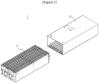
FIG. 1 is a view illustrating a battery module in the related art.FIG. 2 is a view illustrating a cross-section of the battery module inFIG. 1 . - In a
battery module 1 in the related art, an outermost peripheral battery cell of a battery cell stack made by stacking a plurality ofbattery cells 11 is positioned while being in direct contact with amodule case 20. In this case, when the number ofbattery cells 11, which constitute thebattery module 1, is increased, a performance deviation occurs for each of thebattery cells 11 disposed in thebattery module 1, and the performance deviation ultimately and inevitably affects the performance of the battery pack made by connecting the battery modules in parallel or series. - Because the
battery cell 11 is a heat generation element, a temperature of thebattery cell 11 is raised when tests related to outputs, rapid charging, lifespans, and the like are performed. However, because one surface of the battery cell, which is positioned at the outermost periphery in thebattery module 1, is in contact with themodule case 20 of the battery module instead of the cell, the effect of the temperature, which affects the performance of the battery cell, is lower than that of a battery cell positioned at a center of the battery module. For this reason, the performance of thebattery module 1 may be determined depending on the outermost peripheral cell. As a result, the performance of the battery module may generally deteriorate. - The present disclosure attempts to provide a battery module, which is capable of minimizing a performance deviation and a temperature deviation between battery cells caused by positions in a battery module, and a battery pack including the same.
- Technical problems of the present disclosure are not limited to the aforementioned technical problems, and other technical problems, which are not mentioned above, may be clearly understood by those skilled in the art from the following descriptions.
- In order to achieve the above-mentioned object, a battery module according to an embodiment of the present disclosure includes a battery cell stack in which a plurality of battery cells is stacked, a module case configured to accommodate the battery cell stack, a film heater provided between the module case and an outermost peripheral battery cell of the battery cell stack, and a dummy battery cell disposed between the film heater and the outermost peripheral battery cell.
- The dummy battery cell may have the same configuration as the plurality of battery cells and may not be electrically connected to the plurality of battery cells.
- The dummy battery cell may not be charged or discharged.
- The battery module may further include a first temperature sensor attached to the dummy battery cell.
- The battery module may further include a second temperature sensor attached to the battery cell disposed at an innermost side among the plurality of battery cells.
- The battery module may further include a controller configured to control a first temperature measured by the first temperature sensor and a second temperature measured by the second temperature sensor so that the first and second temperatures are equally maintained.
- The controller may be connected to the film heater and heat the film heater on the basis of a result of monitoring the first and second temperatures.
- Pressure applied to each of the plurality of battery cells may be equal to one another.
- The film heater may be configured as at least one a carbon element, a copper foil busbar, a silver busbar, a base PET film, and a Laminex film that are heat generation elements.
- According to another embodiment of the present disclosure, a battery pack may include at least one battery module described above.
- According to the battery module and the battery pack including the same according to the embodiment of the present disclosure, the dummy battery cell, which is not charged or discharged, may be disposed at a position of the outermost peripheral battery cell having a relatively low temperature among the battery cells, the film heater may be disposed on the dummy battery cell, and the temperature sensor may be used to uniformly maintain the temperatures between the dummy battery cell and the center battery cell, such that the temperature and pressure of the battery cells may be uniformly maintained, and the deviation in performance and lifespan between the battery cells may be minimized.
- The effects of the present disclosure are not limited to the aforementioned effects, and other effects, which are not mentioned above, will be clearly understood by those skilled in the art from the claims.
-
-
FIG. 1 is a view illustrating a battery module in the related art. -
FIG. 2 is a view illustrating a cross-section of the battery module inFIG. 1 . -
FIG. 3 is a view illustrating a battery module according to an embodiment of the present disclosure. -
FIG. 4 is a view illustrating a state in which the battery module inFIG. 3 is disassembled. -
FIG. 5 is a view illustrating a cross-section taken along line A-A' inFIG. 3 . -
FIG. 6 is a conceptual view illustrating a configuration in which the battery module according to the embodiment of the present disclosure is connected to a controller. - Hereinafter, several exemplary embodiments of the present disclosure will be described in detail with reference to the accompanying drawings so that those with ordinary skill in the art to which the present disclosure pertains may easily carry out the exemplary embodiments. The present disclosure may be implemented in various different ways and is not limited to the embodiments described herein.
- A part irrelevant to the description will be omitted to clearly describe the present disclosure, and the same or similar constituent elements will be designated by the same reference numerals throughout the specification.
- In addition, a size and thickness of each constituent element illustrated in the drawings are arbitrarily shown for convenience of description, but the present disclosure is not limited thereto. In order to clearly describe several layers and regions, thicknesses thereof are enlarged in the drawings. In the drawings, the thicknesses of some layers and regions are exaggerated for convenience of description.
- In addition, when one component such as a layer, a film, a region, or a plate is described as being positioned "above" or "on" another component, one component can be positioned "directly on" another component, and one component can also be positioned on another component with other components interposed therebetween. On the contrary, when one component is described as being positioned "directly above" another component, there is no component therebetween. In addition, when a component is described as being positioned "above" or "on" a reference part, the component may be positioned "above" or "below" the reference part, and this configuration does not necessarily mean that the component is positioned "above" or "on" the reference part in a direction opposite to gravity.
- Throughout the specification, unless explicitly described to the contrary, the word "comprise/include" and variations such as "comprises/includes" or "comprising/including" will be understood to imply the inclusion of stated elements, not the exclusion of any other elements.
- Hereinafter, a battery module according to an embodiment of the present disclosure will be described with reference to
FIGS. 3 to 6 . -
FIG. 3 is a view illustrating a battery module according to an embodiment of the present disclosure,FIG. 4 is a view illustrating a state in which the battery module inFIG. 3 is disassembled,FIG. 5 is a view illustrating a cross-section taken along line A-A' inFIG. 3 , andFIG. 6 is a conceptual view illustrating a configuration in which the battery module according to the embodiment of the present disclosure is connected to a controller. - With reference to
FIGS. 3 to 6 , abattery module 10 according to an embodiment of the present disclosure includes abattery cell stack 100 made bystacking battery cells 110, amodule case 200 configured to accommodate thebattery cell stack 100,dummy battery cells 111 provided between themodule case 200 and outermost peripheral battery cells, andfilm heaters 300 provided between themodule case 200 and thedummy battery cells 111. - The
battery cell 110 may be a secondary battery and configured as a pouch-type secondary battery. Thebattery cells 110 may be provided as a plurality ofbattery cells 110, and the plurality ofbattery cells 110 are stacked on one another and electrically connected to one another, thereby constituting the battery cell stack. The plurality of battery cells may each include an electrode assembly, a case configured to accommodate the electrode assembly, and electrode leads protruding from the electrode assembly. The electrode assembly may include a positive plate, a negative plate, a separator, and the like. The case may be configured as a laminated sheet configured to accommodate the electrode assembly and made of a resin layer and a metal layer. The electrode lead may protrude from the case and be electrically connected to the electrode assembly. The electrode leads may be provided at two opposite ends of thebattery cell 110. According to the embodiment of the present disclosure, the battery cell has a structure in which the two electrode leads are opposite to each other and protrude from the two opposite ends of thebattery cell 110. - According to the embodiment of the present disclosure, the
module case 200 may have an upper surface, a lower surface, a left surface, and a right surface to accommodate thebattery cell stack 100. However, themodule case 200 may include a U-shaped module case, and an upper plate configured to cover an opened upper side of the U-shaped module case. Alternatively, themodule case 200 may include an inverted U-shaped module case, and a lower plate configured to cover a lower side of the module case. Themodule case 200 may protect thebattery cells 110 and the components connected to thebattery cells 110 from an external physical impact. - The
dummy battery cell 111 is provided between themodule case 200 and the outermostperipheral battery cell 110 of thebattery cell stack 100. Thedummy battery cell 111 is a cell that is configured to be identical to thebattery cell 110. Thedummy battery cells 111 are disposed at two opposite ends of thebattery cell stack 100. Thedummy battery cell 111 is not electrically connected, such that thedummy battery cell 111 is not charged or discharged. Thedummy battery cell 111 may serve to absorb a pressure generated when thebattery cells 110 swell. In addition, the battery cell, which is disposed at the outermost side and thus is large in temperature deviation and pressure deviation with respect to the battery cell disposed at the center and causes deterioration in overall performance of thebattery module 10 in the related art caused by the degradation of performance, is provided as thedummy battery cell 111 that is not charged or discharged. Therefore, even if the temperature deviation and the pressure deviation between thedummy battery cells 111 are increased, the increase in temperature deviation and pressure deviation may not affect the overall performance of thebattery module 10. Further, because all thebattery cells 110, which are electrically connected and charged or discharged, are adjacent to one another or thedummy battery cells 111, thebattery cells 110 may receive the same pressure. That is, in the related art, because one surface of thebattery cell 110 positioned at the outermost periphery necessarily adjoins other components (themodule case 200 or the like) and is placed in a different environment fromother battery cells 110 disposed inward, a difference in pressure occurs between these battery cells. In contrast, in the case of the present embodiment, thedummy battery cells 111 are provided as described above, all thebattery cells 110 may receive the same pressure. - The
film heater 300 is provided between themodule case 200 and thedummy battery cell 111 of thebattery cell stack 100. Therefore, thefilm heater 300 may raise the temperature of thedummy battery cell 111 adjacent to thefilm heater 300. Thefilm heater 300 may be configured as a carbon element, a copper foil busbar, a silver busbar, a base PET film, and a Laminex film that are heat generation elements. The film having the above-mentioned structure may sometimes be used to improve heating efficiency. - Further, as illustrated in
FIG. 5 , in order to minimize the performance deviation between thebattery cells 110 in accordance with the positions of thebattery cells 110 in thebattery module 10, afirst temperature sensor 410 is mounted on thedummy battery cell 111, and asecond temperature sensor 420 is mounted on thebattery cell 110 positioned at the central portion. The temperature of thebattery cell 110 and the temperature of thedummy battery cell 111 are monitored by the first and second temperature sensors, which may minimize the temperature deviation between the battery cells of thebattery cell stack 100. That is, as illustrated inFIG. 6 , the first andsecond temperature sensors controller 500, and thecontroller 500 may acquire a first temperature measured by thefirst temperature sensor 410 and a second temperature measured by thesecond temperature sensor 420. When thecontroller 500 determines that the temperature of thedummy battery cell 111 is low on the basis of the measured temperature, thecontroller 500 may perform control to heat thefilm heater 300, thereby eliminating the temperature deviation between thebattery cell 110 and thedummy battery cell 111. - In case that the temperature of the
dummy battery cell 111 disposed outward and the temperature of thebattery cell 110 at the central portion are monitored and controlled to be equal to each other, the temperatures of thebattery cells 110 disposed between thedummy battery cells 111 and thebattery cell 110 at the central portion may also be uniformly maintained. In addition, because thedummy battery cell 111 absorbs a pressure applied to thebattery cells 110, the pressure applied to thebattery cells 110 other than thedummy battery cell 111 may be uniformly maintained regardless of the positions of thebattery cells 111 in thebattery module 10. Because the temperature and the pressure may be uniformly maintained regardless of the positions of thebattery cells 110 in thebattery module 10 as described above, the cell characteristics and degradation rates of thebattery cells 110 may be uniformly maintained. Therefore, the deviations between the characteristics and degradation rates between thebattery cells 110 are reduced, it is possible to prevent a situation in which the problems occurring on some of thebattery cells 110, particularly, thebattery cells 110 disposed outward degrade the overall performance of thebattery module 10. - Meanwhile, the present embodiment has been described in which the
film heater 300 corresponds to an overall area of thedummy battery cell 111, but the present disclosure is not limited thereto. The size of thefilm heater 300 may be reduced within a range in which thefilm heater 300 does not overlap the electrode lead. In this case, the position of thefilm heater 300 may be close to a central portion of thedummy battery cell 111. In addition, the present embodiment has been described in which thefilm heater 300 is disposed only on thedummy battery cell 111, but the present disclosure is not limited thereto. Even when thefilm heater 300 is disposed between thebattery cells 110 disposed inward, thefilm heater 300 may be controlled to locally raise the temperatures of thebattery cells 110, as necessary. Further, the positions and sizes of thetemperature sensors temperature sensors battery cell 110. - The above-mentioned
battery module 10 may be included in a battery pack. The battery pack may be a structure made by packing one or more battery modules according to the present embodiment while adding a cooling device, a battery management system (BMS), which manages a temperature or voltage of the battery, and the like. - The battery pack may be applied to various devices. Examples of such devices may include transportation means such as an electric bicycle, an electric vehicle, and a hybrid vehicle, but the present disclosure is not limited thereto, and may be applied to various devices that may use the battery module. These configurations may also belong to the scope of the present disclosure.
- While the exemplary embodiments of the present disclosure have been illustrated and described above, the present disclosure is not limited to the specific exemplary embodiments, and various modifications can of course be made by those skilled in the art to which the present disclosure pertains without departing from the subject matter of the present disclosure as claimed in the claims. Further, the modifications should not be appreciated individually from the technical spirit or prospect of the present disclosure.
-
- 100: Battery cell stack
- 110: Battery cell
- 111: Dummy battery cell
- 200: Module case
- 300: Film heater
- 410: First temperature sensor
- 420: Second temperature sensor
Claims (10)
- A battery module comprising:a battery cell stack in which a plurality of battery cells is stacked;a module case configured to accommodate the battery cell stack;a film heater provided between the module case and an outermost peripheral battery cell of the battery cell stack; anda dummy battery cell disposed between the film heater and the outermost peripheral battery cell.
- The battery module of claim 1, wherein:
the dummy battery cell has the same configuration as the plurality of battery cells and is not electrically connected to the plurality of battery cells. - The battery module of claim 2, wherein:
the dummy battery cell is not charged or discharged. - The battery module of claim 1, further comprising:
a first temperature sensor attached to the dummy battery cell. - The battery module of claim 4, further comprising:
a second temperature sensor attached to the battery cell disposed at an innermost side among the plurality of battery cells. - The battery module of claim 5, further comprising:
a controller configured to control a first temperature measured by the first temperature sensor and a second temperature measured by the second temperature sensor so that the first and second temperatures are equally maintained. - The battery module of claim 6, wherein:
the controller is connected to the film heater and heats the film heater on the basis of a result of monitoring the first and second temperatures. - The battery module of claim 1, wherein:
pressure applied to each of the plurality of battery cells are equal to one another. - The battery module of claim 1, wherein:
the film heater is configured as at least one a carbon element, a copper foil busbar, a silver busbar, a base PET film, and a Laminex film that are heat generation elements. - A battery pack comprising the battery module according to claim 1.
Applications Claiming Priority (2)
| Application Number | Priority Date | Filing Date | Title |
|---|---|---|---|
| KR1020220180416A KR20240098557A (en) | 2022-12-21 | 2022-12-21 | Battery module and battery pack including the same |
| PCT/KR2023/018298 WO2024136142A1 (en) | 2022-12-21 | 2023-11-14 | Battery module and battery pack including same |
Publications (2)
| Publication Number | Publication Date |
|---|---|
| EP4517935A1 true EP4517935A1 (en) | 2025-03-05 |
| EP4517935A4 EP4517935A4 (en) | 2025-04-02 |
Family
ID=91589190
Family Applications (1)
| Application Number | Title | Priority Date | Filing Date |
|---|---|---|---|
| EP23907428.9A Pending EP4517935A4 (en) | 2022-12-21 | 2023-11-14 | BATTERY MODULE AND BATTERY PACK COMPRISING SAME |
Country Status (5)
| Country | Link |
|---|---|
| EP (1) | EP4517935A4 (en) |
| JP (1) | JP2025516911A (en) |
| KR (1) | KR20240098557A (en) |
| CN (1) | CN119487674A (en) |
| WO (1) | WO2024136142A1 (en) |
Family Cites Families (8)
| Publication number | Priority date | Publication date | Assignee | Title |
|---|---|---|---|---|
| JP5462711B2 (en) * | 2010-05-21 | 2014-04-02 | 古河電池株式会社 | Battery module |
| KR101827123B1 (en) * | 2016-06-03 | 2018-02-07 | 한온시스템 주식회사 | End cell heater assembly, and fuel cell stack having the same |
| KR102764259B1 (en) * | 2019-01-09 | 2025-02-07 | 현대자동차주식회사 | Fuel cell stack |
| KR102716363B1 (en) * | 2019-05-22 | 2024-10-10 | 현대자동차주식회사 | Fuel cell stack |
| KR102418265B1 (en) * | 2019-08-08 | 2022-07-07 | 주식회사 엘지에너지솔루션 | Battery Pack Comprising Heating Member |
| KR20210090917A (en) * | 2020-01-13 | 2021-07-21 | 주식회사 엘지에너지솔루션 | Battery module and battery pack including the same |
| FR3116157B1 (en) * | 2020-11-12 | 2023-02-10 | Commissariat Energie Atomique | ELECTROCHEMICAL STORAGE DEVICE WITH IMPROVED THERMAL MANAGEMENT |
| CN213816308U (en) * | 2020-11-30 | 2021-07-27 | 贵州万峰博亿能科技有限公司 | Improved lithium iron phosphate lithium ion power battery structure |
-
2022
- 2022-12-21 KR KR1020220180416A patent/KR20240098557A/en active Pending
-
2023
- 2023-11-14 CN CN202380046637.1A patent/CN119487674A/en active Pending
- 2023-11-14 JP JP2024569013A patent/JP2025516911A/en active Pending
- 2023-11-14 EP EP23907428.9A patent/EP4517935A4/en active Pending
- 2023-11-14 WO PCT/KR2023/018298 patent/WO2024136142A1/en not_active Ceased
Also Published As
| Publication number | Publication date |
|---|---|
| WO2024136142A1 (en) | 2024-06-27 |
| EP4517935A4 (en) | 2025-04-02 |
| KR20240098557A (en) | 2024-06-28 |
| JP2025516911A (en) | 2025-05-30 |
| CN119487674A (en) | 2025-02-18 |
Similar Documents
| Publication | Publication Date | Title |
|---|---|---|
| US20230155243A1 (en) | Battery module and battery pack including the same | |
| EP3467903B1 (en) | Battery pack | |
| EP4131584B1 (en) | Battery module including thermal insulation member | |
| US10804578B2 (en) | Battery module, battery pack and vehicle having same | |
| US20240222781A1 (en) | Battery Module and Battery Pack Including the Same | |
| KR102917125B1 (en) | Battery module and battery pack including the same | |
| EP3907811B1 (en) | Battery module and battery pack including the same | |
| US20240387900A1 (en) | Battery module and battery pack including the same | |
| JP7683895B2 (en) | Pouch-type battery cell with improved safety and battery module including the same | |
| US11894537B2 (en) | Battery module and battery pack including the same | |
| EP4181275B1 (en) | Battery module and battery pack including same | |
| KR102892940B1 (en) | Battery module and battery pack including the same | |
| EP4181292B1 (en) | Battery pack including battery modules | |
| KR20210090917A (en) | Battery module and battery pack including the same | |
| JP2021526725A (en) | Battery module, battery pack including it and automobile | |
| US12620649B2 (en) | Battery module and manufacturing method of the same | |
| KR102767817B1 (en) | A battery pack comprising a contact-type cooling plate and device with it | |
| CN119487674A (en) | Battery module and battery pack including the battery module | |
| KR20250127514A (en) | Battery cell and battery module including the same | |
| KR20250096443A (en) | Battery module and battery pack including the same | |
| KR20230170553A (en) | Temperature sensing assembly and battery module including the same | |
| KR20220036236A (en) | Battery module including battery cells with electrode leads of different thicknesses |
Legal Events
| Date | Code | Title | Description |
|---|---|---|---|
| STAA | Information on the status of an ep patent application or granted ep patent |
Free format text: STATUS: THE INTERNATIONAL PUBLICATION HAS BEEN MADE |
|
| PUAI | Public reference made under article 153(3) epc to a published international application that has entered the european phase |
Free format text: ORIGINAL CODE: 0009012 |
|
| STAA | Information on the status of an ep patent application or granted ep patent |
Free format text: STATUS: REQUEST FOR EXAMINATION WAS MADE |
|
| 17P | Request for examination filed |
Effective date: 20241127 |
|
| AK | Designated contracting states |
Kind code of ref document: A1 Designated state(s): AL AT BE BG CH CY CZ DE DK EE ES FI FR GB GR HR HU IE IS IT LI LT LU LV MC ME MK MT NL NO PL PT RO RS SE SI SK SM TR |
|
| A4 | Supplementary search report drawn up and despatched |
Effective date: 20250303 |
|
| RIC1 | Information provided on ipc code assigned before grant |
Ipc: H01M 50/211 20210101ALN20250225BHEP Ipc: H01M 50/20 20210101ALI20250225BHEP Ipc: H01M 10/48 20060101ALI20250225BHEP Ipc: H01M 10/6571 20140101ALI20250225BHEP Ipc: H01M 10/617 20140101AFI20250225BHEP |
|
| DAV | Request for validation of the european patent (deleted) | ||
| DAX | Request for extension of the european patent (deleted) |