EP4517924A1 - Temperature sensing assembly, and battery module comprising same - Google Patents
Temperature sensing assembly, and battery module comprising same Download PDFInfo
- Publication number
- EP4517924A1 EP4517924A1 EP23819996.2A EP23819996A EP4517924A1 EP 4517924 A1 EP4517924 A1 EP 4517924A1 EP 23819996 A EP23819996 A EP 23819996A EP 4517924 A1 EP4517924 A1 EP 4517924A1
- Authority
- EP
- European Patent Office
- Prior art keywords
- substrate
- bridge
- sensing assembly
- temperature sensor
- temperature sensing
- Prior art date
- Legal status (The legal status is an assumption and is not a legal conclusion. Google has not performed a legal analysis and makes no representation as to the accuracy of the status listed.)
- Pending
Links
Images





Classifications
-
- H—ELECTRICITY
- H01—ELECTRIC ELEMENTS
- H01M—PROCESSES OR MEANS, e.g. BATTERIES, FOR THE DIRECT CONVERSION OF CHEMICAL ENERGY INTO ELECTRICAL ENERGY
- H01M10/00—Secondary cells; Manufacture thereof
- H01M10/42—Methods or arrangements for servicing or maintenance of secondary cells or secondary half-cells
- H01M10/48—Accumulators combined with arrangements for measuring, testing or indicating the condition of cells, e.g. the level or density of the electrolyte
- H01M10/486—Accumulators combined with arrangements for measuring, testing or indicating the condition of cells, e.g. the level or density of the electrolyte for measuring temperature
-
- G—PHYSICS
- G01—MEASURING; TESTING
- G01K—MEASURING TEMPERATURE; MEASURING QUANTITY OF HEAT; THERMALLY-SENSITIVE ELEMENTS NOT OTHERWISE PROVIDED FOR
- G01K1/00—Details of thermometers not specially adapted for particular types of thermometer
- G01K1/14—Supports; Fastening devices; Arrangements for mounting thermometers in particular locations
-
- G—PHYSICS
- G01—MEASURING; TESTING
- G01K—MEASURING TEMPERATURE; MEASURING QUANTITY OF HEAT; THERMALLY-SENSITIVE ELEMENTS NOT OTHERWISE PROVIDED FOR
- G01K1/00—Details of thermometers not specially adapted for particular types of thermometer
- G01K1/14—Supports; Fastening devices; Arrangements for mounting thermometers in particular locations
- G01K1/146—Supports; Fastening devices; Arrangements for mounting thermometers in particular locations arrangements for moving thermometers to or from a measuring position
-
- H—ELECTRICITY
- H01—ELECTRIC ELEMENTS
- H01M—PROCESSES OR MEANS, e.g. BATTERIES, FOR THE DIRECT CONVERSION OF CHEMICAL ENERGY INTO ELECTRICAL ENERGY
- H01M10/00—Secondary cells; Manufacture thereof
- H01M10/42—Methods or arrangements for servicing or maintenance of secondary cells or secondary half-cells
- H01M10/425—Structural combination with electronic components, e.g. electronic circuits integrated to the outside of the casing
- H01M10/4257—Smart batteries, e.g. electronic circuits inside the housing of the cells or batteries
-
- H—ELECTRICITY
- H01—ELECTRIC ELEMENTS
- H01M—PROCESSES OR MEANS, e.g. BATTERIES, FOR THE DIRECT CONVERSION OF CHEMICAL ENERGY INTO ELECTRICAL ENERGY
- H01M50/00—Constructional details or processes of manufacture of the non-active parts of electrochemical cells other than fuel cells, e.g. hybrid cells
- H01M50/20—Mountings; Secondary casings or frames; Racks, modules or packs; Suspension devices; Shock absorbers; Transport or carrying devices; Holders
- H01M50/204—Racks, modules or packs for multiple batteries or multiple cells
- H01M50/207—Racks, modules or packs for multiple batteries or multiple cells characterised by their shape
- H01M50/211—Racks, modules or packs for multiple batteries or multiple cells characterised by their shape adapted for pouch cells
-
- H—ELECTRICITY
- H01—ELECTRIC ELEMENTS
- H01M—PROCESSES OR MEANS, e.g. BATTERIES, FOR THE DIRECT CONVERSION OF CHEMICAL ENERGY INTO ELECTRICAL ENERGY
- H01M50/00—Constructional details or processes of manufacture of the non-active parts of electrochemical cells other than fuel cells, e.g. hybrid cells
- H01M50/50—Current conducting connections for cells or batteries
-
- H—ELECTRICITY
- H01—ELECTRIC ELEMENTS
- H01M—PROCESSES OR MEANS, e.g. BATTERIES, FOR THE DIRECT CONVERSION OF CHEMICAL ENERGY INTO ELECTRICAL ENERGY
- H01M10/00—Secondary cells; Manufacture thereof
- H01M10/42—Methods or arrangements for servicing or maintenance of secondary cells or secondary half-cells
- H01M10/48—Accumulators combined with arrangements for measuring, testing or indicating the condition of cells, e.g. the level or density of the electrolyte
- H01M10/482—Accumulators combined with arrangements for measuring, testing or indicating the condition of cells, e.g. the level or density of the electrolyte for several batteries or cells simultaneously or sequentially
-
- H—ELECTRICITY
- H01—ELECTRIC ELEMENTS
- H01M—PROCESSES OR MEANS, e.g. BATTERIES, FOR THE DIRECT CONVERSION OF CHEMICAL ENERGY INTO ELECTRICAL ENERGY
- H01M2220/00—Batteries for particular applications
- H01M2220/20—Batteries in motive systems, e.g. vehicle, ship, plane
-
- Y—GENERAL TAGGING OF NEW TECHNOLOGICAL DEVELOPMENTS; GENERAL TAGGING OF CROSS-SECTIONAL TECHNOLOGIES SPANNING OVER SEVERAL SECTIONS OF THE IPC; TECHNICAL SUBJECTS COVERED BY FORMER USPC CROSS-REFERENCE ART COLLECTIONS [XRACs] AND DIGESTS
- Y02—TECHNOLOGIES OR APPLICATIONS FOR MITIGATION OR ADAPTATION AGAINST CLIMATE CHANGE
- Y02E—REDUCTION OF GREENHOUSE GAS [GHG] EMISSIONS, RELATED TO ENERGY GENERATION, TRANSMISSION OR DISTRIBUTION
- Y02E60/00—Enabling technologies; Technologies with a potential or indirect contribution to GHG emissions mitigation
- Y02E60/10—Energy storage using batteries
Definitions
- the present invention relates to a temperature sensing assembly for sensing a temperature of a cell stack, and a battery module including the temperature sensing assembly.
- lithium secondary batteries attract interest due to merits that the lithium secondary batteries are freely chargeable and dischargeable because of having little memory effect compared to nickel-based secondary batteries, and have very low self-discharge rate and high energy density.
- a lithium-based oxide and a carbonaceous material are mainly used as a positive electrode active material and a negative electrode active material, respectively.
- the lithium secondary battery includes an electrode assembly, in which a positive electrode plate and a negative electrode plate that are coated with the positive electrode active material and the negative electrode active material, respectively, are disposed with a separator therebetween, and an exterior material, i.e., a battery case, which seals and accommodates the electrode assembly together with an electrolyte.
- the lithium secondary batteries may be classified into a can type secondary battery, in which an electrode assembly is embedded in a metal can, and a pouch type secondary battery in which an electrode assembly is embedded in a pouch made of an aluminum laminate sheet.
- the plurality of battery cells are connected to each other in parallel or in series to provide a battery cell stack so that capacity and output are improved.
- one or more battery modules may be mounted together with various control and protection systems such as a battery management system (BMS) and cooling system, to provide a battery pack.
- BMS battery management system
- cooling system to provide a battery pack.
- a means for detecting a change in temperature of the battery cell is required, and thus, a temperature sensor such as a thermistor is disposed in the battery module to check and control an operational state in real time or at fixed intervals.
- An object of the present invention for solving the above problems is to provide a temperature sensing assembly, which prevents a temperature sensor from being damaged and has improved accuracy and reliability, and a battery module including the temperature sensing assembly.
- a temperature sensing assembly may include: a substrate; a temperature sensor mounted on the substrate; a bridge which is coupled to the substrate and in which a hole facing the temperature sensor is defined; and a compression member disposed between the bridge and the substrate at each of both sides of the temperature sensor.
- the bridge may be coupled at an upper side of the substrate.
- the bridge may include: a body part to which the substrate is coupled; and an extension part that extends from the body part, is spaced a predetermined distance from the substrate, and is in contact with the compression member.
- a hole may be defined in the extension part.
- the substrate may include: a coupling part coupled to the bridge; and a mounting part which is spaced a predetermined distance from the bridge and on which the temperature sensor is mounted.
- An adhesive layer may be provided between the coupling part and the bridge.
- the substrate may further include an inclined part that connects the coupling part to the mounting part and is provided to be tilted with respect to the mounting part.
- the compression member may be bonded to each of the substrate and the bridge.
- the hole may not overlap the compression member in a penetration direction of the hole.
- a battery module may include: a housing; a cell stack accommodated in the housing and including a plurality of battery cells disposed to be parallel to each other; and a temperature sensing assembly that senses a temperature of the cell stack.
- the temperature sensing assembly may include: a substrate disposed above the cell stack; a temperature sensor mounted on the substrate; a bridge which is coupled to the substrate and in which a hole facing the temperature sensor is defined; and a compression member disposed between the bridge and the substrate at each of both sides of the temperature sensor.
- the battery module may further include a busbar frame on which a busbar connected to the plurality of battery cells is mounted.
- the bridge may be pivotably connected to the busbar frame.
- At least a portion of the temperature sensing assembly may be disposed between an upper plate of the housing and the cell stack.
- the compression member may not interfere with the temperature sensor and the hole of the bridge may be defined to face the temperature sensor, so that the temperature sensor enters the hole even when the compression member is excessively compressed. Accordingly, the temperature sensor may be prevented from being damaged.
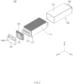
- FIG. 1 is a perspective view illustrating an outer appearance of a battery module according to an embodiment of the present invention.
- FIG. 2 is an exploded perspective view of the battery module illustrated in FIG. 1 .
- a battery module 100 may include a cell stack 110 and a housing 120.
- the cell stack 110 may include a plurality of battery cells 111 disposed to be parallel to each other.
- the cell stack 110 may be accommodated in the housing 120.
- the plurality of battery cells 111 may be disposed to face each other in a first direction (e.g., a direction parallel to an Y axis). In more detail, the plurality of battery cells 111 may be stacked in the first direction. In addition, each of the battery cells 111 may be disposed to be elongated in a second direction (e.g., a direction parallel to an X axis) perpendicular to the first direction.
- the first direction may be a direction parallel to a full-width direction of the housing 120, and the second direction may be a direction parallel to a full-length direction of the housing 120.
- Each of the battery cells 111 may be a pouch type battery cell.
- the pouch type battery cell the number of stacked battery cells per unit area may be maximized, and thus an energy density of the battery module 100 may increase.
- the battery cell 111 provided in a pouch type may be manufactured by accommodating an electrode assembly, which includes a positive electrode, a negative electrode, and a separator, in a cell case in which a laminate sheet is molded, and then, thermally fusing and sealing the cell case.
- the battery cell 111 is not necessarily provided in a pouch type, and it is apparent that the battery cell 111 may be provided in a prismatic type, a cylinder type, or other various types under a level at which storage capacity required by a device on which the battery cell 111 is mounted in the future is achieved.
- Each of the battery cells 111 may be provided with a pair of electrode leads 112.
- the pair of electrode leads 112 may protrude at opposite directions, and may protrude to be parallel to a longitudinal direction of the battery cell 111.
- an embodiment of the present invention is not limited thereto, and it is also possible that the pair of electrode leads 112 protrude to be parallel to each other in the same direction.
- the cell stack 110 may be provided with at least one heat dissipating pad.
- the heat dissipating pad may be disposed between the plurality of battery cells 111, or disposed to cover the outermost battery cell 111.
- the housing 120 may provide an outer appearance of the battery module 100.
- the housing 120 may have a metal material having high rigidity.
- the housing 120 may have various structures.
- the housing 120 may be a mono-frame.
- the mono-frame may be a metal plate in which an upper plate 121, a lower plate, and a pair of side plates are integrated with each other.
- the housing 120 may have a structure in which a U-shaped frame and the upper plate 121 are coupled to each other.
- the U-shaped frame may be a metal plate in which a lower plate and side plates are coupled to or integrated with each other.
- the structure of the housing 120 may be provided as a structure, in which L-shaped frames are coupled to each other, and may be provided as various structures that are not described in the foregoing examples.
- the housing 120 may have an inner space, and the cell stack 110 may be accommodated in the inner space.
- the housing 120 may include the upper plate 121, the lower plate, and the pair of side plates.
- each of both ends in the full-length direction may be opened, and may be covered by an end plate 140 to be described later.
- the battery module 100 may further include a busbar frame 130 and the end plate 140.
- the busbar frame 130 may be disposed at each of both sides in a full-length direction of the cell stack 110. At least one busbar 131 may be mounted on the busbar frame 130, and each of the busbars 131 may be connected to the electrode leads 112 of the battery cells 111.
- the busbar 131 may be a component for electrically connecting the plurality of battery cells 111 to an external device.
- the end plate 140 may be disposed outside the busbar frame 130. That is, the busbar frame 130 may be disposed between the cell stack 110 and the end plate 140.
- the end plate 140 may be coupled to the housing 120.
- the end plate 140 may cover each of both the opened ends of the housing 120.
- An opening 140h may be defined in the end plate 140, and an electrical connection of the busbar 131 may be achieved through the opening 140h. That is, the busbar 131 of one battery module 100 may be electrically connected to another battery module 100 or a battery disconnect unit (BDU) through the opening 140h.
- BDU battery disconnect unit
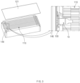
- FIG. 3 is a view illustrating a temperature sensing assembly provided in a battery module according to an embodiment of the present invention.
- FIG. 4 is an exploded perspective view of a temperature sensing assembly according to an embodiment of the present invention.
- FIG. 5 is a plan view of a temperature sensing assembly according to an embodiment of the present invention.
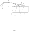
- FIG. 6 is a schematic view for explaining an operation of a temperature sensing assembly according to an embodiment of the present invention.
- the battery module 100 may include a temperature sensing assembly 10 that senses a temperature of the cell stack 110.
- the temperature sensing assembly 10 may be connected to the busbar frame 130.
- the temperature sensing assembly 10 may be pivotably connected to the busbar frame 130.
- the temperature sensing assembly 10 may be hinge-coupled to the busbar frame 130.
- the temperature sensing assembly 10 may be in reliably close contact with the cell stack 110, and may accurately measure the temperature of the cell stack 110.
- the temperature sensor 40 may be mounted on the substrate 20.
- the temperature sensor 40 may be a device capable of temperature sensing.
- the temperature sensor 40 may be fixed onto the substrate 20 by soldering.
- the temperature sensor 40 may include a thermistor.
- the thermistor is a semiconductor device using a phenomenon in which a resistance value varies depending on temperature. There are advantages that the thermistor is small in size and capable of measuring the temperature despite a rapid change in temperature or a slight change in temperature.
- the substrate 20 may be a flexible printed circuit board (FPCB).
- the substrate 20 may be electrically connected to the temperature sensor 40, and may transmit the temperature information measured by the temperature sensor 40 to the outside.
- the temperature information measured by the temperature sensor 40 may be transmitted to another device outside the battery module 100.
- the temperature information measured by the temperature sensor 40 may be transmitted to a battery management system (BMS) outside the battery module 100 to be used to control the battery module 100.
- BMS battery management system
- the bridge 30 may be coupled at an upper side of the substrate 20.
- the bridge 30 may have higher rigidity than the substrate 20 and support the substrate 20.
- the bridge 30 may be provided to be elongated approximately in the full-length direction of the cell stack 110.
- the bridge 30 may include a plurality of regions having different tilt angles.
- the bridge 30 may be provided as one body, but is not limited thereto.
- the bridge 30 may be pivotably connected to the busbar frame 130.
- the bridge 30 may be hinge-coupled to an upper end of the busbar frame 130 so as to be pivotable with respect to the busbar frame 130.
- the bridge 30 may pivot together with the substrate 20.
- the bridge 30 may pivot around a shaft parallel to a stacking direction of the cell stack 110.
- the hole 34 facing the temperature sensor 40 on the substrate 20 may be defined in the bridge 30.
- the temperature sensor 40 may be inserted into the hole 34. That is, the temperature sensor 40 may be prevented from interfering with the bridge 30.
- the substrate 20 may include a coupling part 21 coupled to the bridge 30, and a mounting part 22 which is spaced a predetermined distance from the bridge 30 and on which the temperature sensor 40 is mounted.
- the substrate 20 may further include an inclined part 23 that connects the coupling part 21 to the mounting part 22 and is provided to be tilted with respect to the mounting part 22.
- the bridge 30 may include a body part 31 to which the substrate 20 is coupled, and an extension part 32 that extends from the body part 31, is spaced a predetermined distance from the substrate 20, and is in contact with the compression member 50.
- the bridge 30 may further include a connecting part 33 pivotably connected to the busbar frame 130.
- the coupling part 21 of the substrate 20 may be bonded to the bridge 30, and may accordingly be simply coupled to the bridge 30. That is, an adhesive layer 60 may be provided between the coupling part 21 and the bridge 30.
- the adhesive layer 60 may be a double-sided tape.
- the coupling method between the coupling part 21 of the substrate 20 and the body part 31 of the bridge 30 is not limited thereto.
- the mounting part 22 of the substrate 20 may be spaced a predetermined distance from the bridge 30.
- the mounting part 22 may be spaced a predetermined distance from the extension part 32 of the bridge 30. Due to the distance, the temperature sensor 40 and the compression member 50 may be disposed between the substrate 20 and the bridge 30.
- the extension part 32 of the bridge 30 may extend from the body part 31.
- the extension part 32 and the body part 31 may be provided to be parallel to each other or to have different tilts.
- the mounting part 22 of the substrate 20 may be provided to be parallel to the extension part 32 of the bridge 30. Thus, the distance may be uniformly provided in a longitudinal direction of the mounting part 22.
- the temperature sensor 40 may be mounted on the mounting part 22.
- the temperature sensor 40 may be fixed onto the mounting part 22 by soldering.
- the inclined part 23 of the substrate 20 may be disposed between the coupling part 21 and the mounting part 22, and connect the coupling part 21 to the mounting part 22.
- the inclined part 23 may be provided integrally with the coupling part 21 and the mounting part 22.
- An approximate height difference between the coupling part 21 and the mounting part 22 may be achieved due to the inclined part 23. Accordingly, the coupling part 21 may be in close contact with the body part 31 of the bridge 30, and the mounting part 22 may be spaced a predetermine distance from the extension part 32 of the bridge 30.
- the connecting part 33 of the bridge 30 may have a shape that is bent downward from the body part 31.
- the connecting part 33 may be pivotably connected to the busbar frame 130.
- the compression member 50 may be disposed between the substrate 20 and the bridge 30.
- the compression member 50 may be disposed between the mounting part 22 of the substrate 20 and the extension part 32 of the bridge 30.
- the compression member 50 may be bonded to each of the substrate 20 and the bridge 30. That is, the compression member 50 may have a bottom surface bonded to the mounting part 22 of the substrate 20, and a top surface bonded to the extension part 32 of the bridge 30.
- a lower adhesive layer may be provided between the bottom surface of the compression member 50 and a top surface of the mounting part 22, and an upper adhesive layer may be provided between the top surface of the compression member 50 and a bottom surface of the extension part 32.
- Each of the lower adhesive layer and the upper adhesive layer may be a double-sided tape.
- the mounting part 22 of the substrate 20 and the extension part 32 of the bridge 30 may be prevented from being separated or deformed unintentionally.
- the compression member 50 may be configured to be compressed when the substrate 20 is deformed toward the bridge 30.
- the compression member 50 may mitigate the deformation of the substrate 20 and prevent the substrate 20 from interfering with the bridge 30.
- the durability of the temperature sensing assembly 10 may be improved due to the compression member 50.
- the compression member 50 may be a compression pad of which a material itself has elasticity and which is compressed and deformed.
- the material of the compression member 50 is not limited, and the compression member 50 may have a material that is elastically deformed by preset external force.
- the compression member 50 may have a material such as sponge or polyurethane foam, which is elastically deformed, and may be compressed between the bridge 30 and the substrate 20.
- the compression member 50 may be configured to exhibit elasticity due to the shape.
- the compression member 50 may be disposed at both sides of the temperature sensor 40. That is, a portion of the compression member 50 may be disposed at one side of the temperature sensor 40, and the other portion of the compression member 50 may be disposed at the other side of the temperature sensor 40.
- the compression member 50 may include a first compression member 50 disposed at one side of the temperature sensor 40, and a second compression member 50 disposed at the other side of the temperature sensor 40.
- the compression member 50 may not interfere with the temperature sensor 40, and pressure may be prevented from being applied to the temperature sensor 40 when the compression member 50 is compressed.
- the temperature sensor 40 may be prevented from being damaged by the compression member 50, and the substrate 20 may be maintained to be in a state of being adjacent to or in close contact with the cell stack 110. Accordingly, accuracy and reliability of the temperature sensor 40 may be improved.
- the hole 34 defined in the bridge 30 may not overlap the compression member 50 in a penetration direction of the hole 34. Accordingly, the compression member 50 may be prevented from blocking the hole 34, and the temperature sensor 40 may face the hole 34 or enter the hole 34 even when the compression member 50 is compressed.
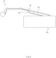
- FIGS. 7 and 8 are views of a temperature sensing assembly according to Comparative Example.
- a hole facing a temperature sensor 40 may not be defined in a bridge 30, and a compression member 50' may cover the temperature sensor 40. That is, the temperature sensor 40 may be buried in the compression member 50'.
- the compression member 50 may not interfere with the temperature sensor 40 and the hole 34 of the bridge 30 may be defined to face the temperature sensor 40, so that the temperature sensor 40 enters the hole 34 even when the compression member 50 is excessively compressed. Accordingly, the temperature sensor 40 may be prevented from being damaged.
- FIG. 9 is an exploded perspective view of a temperature sensing assembly according to another embodiment of the present invention.
- the compression members 50a disposed at both sides of a temperature sensor 40, respectively, may be connected to each other without an interference with the temperature sensor 40.
- the compression members 50a may be provided as one body.
- the compression member 50a may surround the temperature sensor 40. That is, a portion of the compression member 50a may be disposed at one side of the temperature sensor 40, and the other portion of the compression member 50a may be disposed at the other side of the temperature sensor 40.
- a through-hole may be defined in the compression member 50a, and the temperature sensor 40 may be disposed in the through-hole.
- the through-hole may face a hole 34 defined in a bridge 30.
- This embodiment has an advantage that a process of bonding the compression member 50a to a substrate 20 and/or a bridge 30 is simplified.
- Temperature sensing assembly 20 Substrate 21: Coupling part 22: Mounting part 23: Inclined part 30: Bridge 31: Body part 32: Extension part 33: Connecting part 34: Hole 40: Temperature sensor 50: Compression member 60: Adhesive layer 100: Battery module 110: Cell stack 111: Battery cell 120: Housing 130: Busbar frame 140: End plate
Landscapes
- Chemical & Material Sciences (AREA)
- Chemical Kinetics & Catalysis (AREA)
- Electrochemistry (AREA)
- General Chemical & Material Sciences (AREA)
- Engineering & Computer Science (AREA)
- Manufacturing & Machinery (AREA)
- Physics & Mathematics (AREA)
- General Physics & Mathematics (AREA)
- Microelectronics & Electronic Packaging (AREA)
- Battery Mounting, Suspending (AREA)
- Secondary Cells (AREA)
- Connection Of Batteries Or Terminals (AREA)
Abstract
Description
- The present application claims the benefit of the priority of
Korean Patent Application Nos. 10-2022-0070939, filed on June 10, 2022 10-2023-0048466, filed on April 12, 2023 - The present invention relates to a temperature sensing assembly for sensing a temperature of a cell stack, and a battery module including the temperature sensing assembly.
- In modern society, as portable devices such as mobile phones, notebook computers, camcorders and digital cameras, are daily used, the development of technologies in the fields related to mobile devices as above is actively carried out. In addition, secondary batteries that are chargeable and dischargeable are used as power sources for electric vehicles (EV), hybrid electric vehicles (HEV), plug-in hybrid electric vehicles (P-HEV) and the like, which are proposed as solutions to solve problems such as air pollution caused by existing gasoline vehicles and the like, using fossil fuel, and therefore, there is an increasing need for development of the secondary batteries.
- Currently commercialized secondary batteries include nickel-cadmium batteries, nickel-hydrogen batteries, nickel-zinc batteries, lithium secondary batteries, and the like. Among the secondary batteries, the lithium secondary batteries attract interest due to merits that the lithium secondary batteries are freely chargeable and dischargeable because of having little memory effect compared to nickel-based secondary batteries, and have very low self-discharge rate and high energy density.
- In such a lithium secondary battery, a lithium-based oxide and a carbonaceous material are mainly used as a positive electrode active material and a negative electrode active material, respectively. The lithium secondary battery includes an electrode assembly, in which a positive electrode plate and a negative electrode plate that are coated with the positive electrode active material and the negative electrode active material, respectively, are disposed with a separator therebetween, and an exterior material, i.e., a battery case, which seals and accommodates the electrode assembly together with an electrolyte.
- In general, according to the shape of the exterior material, the lithium secondary batteries may be classified into a can type secondary battery, in which an electrode assembly is embedded in a metal can, and a pouch type secondary battery in which an electrode assembly is embedded in a pouch made of an aluminum laminate sheet.
- In secondary batteries used in small-sized devices, two or three battery cells are disposed, but, in secondary batteries used in medium to large-sized devices such as vehicles, a battery module in which a plurality of battery cells are electrically connected to each other is used.
- In this battery module, the plurality of battery cells are connected to each other in parallel or in series to provide a battery cell stack so that capacity and output are improved. Moreover, one or more battery modules may be mounted together with various control and protection systems such as a battery management system (BMS) and cooling system, to provide a battery pack.
- When overvoltage, overcurrent, or overheating occurs in the battery cells included in the battery module, this is highly problematic in terms of safety and operational efficiency of the battery module. As an example, when the pressure or temperature of the battery increases, a decomposition reaction of the active material and multiple side reactions proceed, and accordingly, the temperature of the battery rapidly increases. This rapid temperature increase reaccelerates the reaction between the electrolyte and the electrode. Eventually, thermal runaway in which the temperature of the battery rapidly increases occurs, and, when the temperature increases to a certain level or higher, ignition of the battery may occur, and the battery cell and the battery module including the battery cell explode due to the increased internal pressure of the battery.
- Accordingly, a means for detecting a change in temperature of the battery cell is required, and thus, a temperature sensor such as a thermistor is disposed in the battery module to check and control an operational state in real time or at fixed intervals.
- An object of the present invention for solving the above problems is to provide a temperature sensing assembly, which prevents a temperature sensor from being damaged and has improved accuracy and reliability, and a battery module including the temperature sensing assembly.
- A temperature sensing assembly according to an embodiment of the present invention may include: a substrate; a temperature sensor mounted on the substrate; a bridge which is coupled to the substrate and in which a hole facing the temperature sensor is defined; and a compression member disposed between the bridge and the substrate at each of both sides of the temperature sensor.
- The bridge may be coupled at an upper side of the substrate.
- The bridge may include: a body part to which the substrate is coupled; and an extension part that extends from the body part, is spaced a predetermined distance from the substrate, and is in contact with the compression member.
- A hole may be defined in the extension part.
- The substrate may include: a coupling part coupled to the bridge; and a mounting part which is spaced a predetermined distance from the bridge and on which the temperature sensor is mounted.
- An adhesive layer may be provided between the coupling part and the bridge.
- The substrate may further include an inclined part that connects the coupling part to the mounting part and is provided to be tilted with respect to the mounting part.
- The compression member may be bonded to each of the substrate and the bridge.
- The hole may not overlap the compression member in a penetration direction of the hole.
- A battery module according to an embodiment of the present invention may include: a housing; a cell stack accommodated in the housing and including a plurality of battery cells disposed to be parallel to each other; and a temperature sensing assembly that senses a temperature of the cell stack. The temperature sensing assembly may include: a substrate disposed above the cell stack; a temperature sensor mounted on the substrate; a bridge which is coupled to the substrate and in which a hole facing the temperature sensor is defined; and a compression member disposed between the bridge and the substrate at each of both sides of the temperature sensor.
- The battery module may further include a busbar frame on which a busbar connected to the plurality of battery cells is mounted. The bridge may be pivotably connected to the busbar frame.
- At least a portion of the temperature sensing assembly may be disposed between an upper plate of the housing and the cell stack.
- According to the preferred embodiments of the present invention, even when the cell stack swells, or the pressure is applied to the substrate by the tolerance or the like during the assembling of the battery module, the temperature sensor may be prevented from being damaged by the compression member, and the substrate may be maintained to be in the state of being adjacent to or in close contact with the cell stack. Accordingly, the accuracy and the reliability of the temperature sensor may be improved.
- Moreover, the compression member may not interfere with the temperature sensor and the hole of the bridge may be defined to face the temperature sensor, so that the temperature sensor enters the hole even when the compression member is excessively compressed. Accordingly, the temperature sensor may be prevented from being damaged.
- In addition, the effects may be included which are easily predictable by those skilled in the art from the configurations according to the preferred embodiments of the present invention.
- The following drawings attached in this specification illustrate a preferred embodiment of the present invention and function to make further understood the technical spirit of the present invention along with the detailed description of the invention. The present invention should not be construed as being limited to only the drawings.
-
FIG. 1 is a perspective view illustrating an outer appearance of a battery module according to an embodiment of the present invention. -
FIG. 2 is an exploded perspective view of the battery module illustrated inFIG. 1 . -
FIG. 3 is a view illustrating a temperature sensing assembly provided in a battery module according to an embodiment of the present invention. -
FIG. 4 is an exploded perspective view of a temperature sensing assembly according to an embodiment of the present invention. -
FIG. 5 is a plan view of a temperature sensing assembly according to an embodiment of the present invention. -
FIG. 6 is a schematic view for explaining an operation of a temperature sensing assembly according to an embodiment of the present invention. -
FIGS. 7 and8 are views of a temperature sensing assembly according to Comparative Example. -
FIG. 9 is an exploded perspective view of a temperature sensing assembly according to another embodiment of the present invention. - Hereinafter, preferred embodiments of the present invention will be described in detail with reference to the accompanying drawings to enable those skilled in the art to which the present invention pertains to easily carry out the present invention. The present invention may, however, be embodied in different forms and should not be construed as limited by the embodiments set forth herein.
- The parts unrelated to the description, or the detailed descriptions of related well-known art that may unnecessarily obscure subject matters of the present invention, will be ruled out in order to clearly describe the present invention. Like reference numerals refer to like elements throughout the whole specification.
- Moreover, terms or words used in this specification and claims should not be restrictively interpreted as ordinary meanings or dictionary-based meanings, but should be interpreted as meanings and concepts conforming to the scope of the present invention on the basis of the principle that an inventor can properly define the concept of a term to describe and explain his or her invention in the best ways.
-
FIG. 1 is a perspective view illustrating an outer appearance of a battery module according to an embodiment of the present invention.FIG. 2 is an exploded perspective view of the battery module illustrated inFIG. 1 . - A
battery module 100 according to an embodiment of the present invention may include acell stack 110 and ahousing 120. - The
cell stack 110 may include a plurality ofbattery cells 111 disposed to be parallel to each other. Thecell stack 110 may be accommodated in thehousing 120. - The plurality of
battery cells 111 may be disposed to face each other in a first direction (e.g., a direction parallel to an Y axis). In more detail, the plurality ofbattery cells 111 may be stacked in the first direction. In addition, each of thebattery cells 111 may be disposed to be elongated in a second direction (e.g., a direction parallel to an X axis) perpendicular to the first direction. The first direction may be a direction parallel to a full-width direction of thehousing 120, and the second direction may be a direction parallel to a full-length direction of thehousing 120. - Each of the
battery cells 111 may be a pouch type battery cell. In the pouch type battery cell, the number of stacked battery cells per unit area may be maximized, and thus an energy density of thebattery module 100 may increase. Thebattery cell 111 provided in a pouch type may be manufactured by accommodating an electrode assembly, which includes a positive electrode, a negative electrode, and a separator, in a cell case in which a laminate sheet is molded, and then, thermally fusing and sealing the cell case. However, thebattery cell 111 is not necessarily provided in a pouch type, and it is apparent that thebattery cell 111 may be provided in a prismatic type, a cylinder type, or other various types under a level at which storage capacity required by a device on which thebattery cell 111 is mounted in the future is achieved. - Each of the
battery cells 111 may be provided with a pair of electrode leads 112. The pair of electrode leads 112 may protrude at opposite directions, and may protrude to be parallel to a longitudinal direction of thebattery cell 111. However, an embodiment of the present invention is not limited thereto, and it is also possible that the pair of electrode leads 112 protrude to be parallel to each other in the same direction. - In addition, the
cell stack 110 may be provided with at least one heat dissipating pad. The heat dissipating pad may be disposed between the plurality ofbattery cells 111, or disposed to cover theoutermost battery cell 111. - The
housing 120 may provide an outer appearance of thebattery module 100. Thehousing 120 may have a metal material having high rigidity. - The
housing 120 may have various structures. As one example, thehousing 120 may be a mono-frame. The mono-frame may be a metal plate in which anupper plate 121, a lower plate, and a pair of side plates are integrated with each other. As another example, thehousing 120 may have a structure in which a U-shaped frame and theupper plate 121 are coupled to each other. The U-shaped frame may be a metal plate in which a lower plate and side plates are coupled to or integrated with each other. In addition, the structure of thehousing 120 may be provided as a structure, in which L-shaped frames are coupled to each other, and may be provided as various structures that are not described in the foregoing examples. - The
housing 120 may have an inner space, and thecell stack 110 may be accommodated in the inner space. In more detail, thehousing 120 may include theupper plate 121, the lower plate, and the pair of side plates. In thehousing 120, each of both ends in the full-length direction may be opened, and may be covered by anend plate 140 to be described later. - The
battery module 100 may further include abusbar frame 130 and theend plate 140. - The
busbar frame 130 may be disposed at each of both sides in a full-length direction of thecell stack 110. At least onebusbar 131 may be mounted on thebusbar frame 130, and each of thebusbars 131 may be connected to the electrode leads 112 of thebattery cells 111. Thebusbar 131 may be a component for electrically connecting the plurality ofbattery cells 111 to an external device. - The
end plate 140 may be disposed outside thebusbar frame 130. That is, thebusbar frame 130 may be disposed between thecell stack 110 and theend plate 140. - The
end plate 140 may be coupled to thehousing 120. Theend plate 140 may cover each of both the opened ends of thehousing 120. Anopening 140h may be defined in theend plate 140, and an electrical connection of thebusbar 131 may be achieved through theopening 140h. That is, thebusbar 131 of onebattery module 100 may be electrically connected to anotherbattery module 100 or a battery disconnect unit (BDU) through theopening 140h. -
FIG. 3 is a view illustrating a temperature sensing assembly provided in a battery module according to an embodiment of the present invention.FIG. 4 is an exploded perspective view of a temperature sensing assembly according to an embodiment of the present invention.FIG. 5 is a plan view of a temperature sensing assembly according to an embodiment of the present invention.FIG. 6 is a schematic view for explaining an operation of a temperature sensing assembly according to an embodiment of the present invention. - The
battery module 100 may include atemperature sensing assembly 10 that senses a temperature of thecell stack 110. - At least a portion of the
temperature sensing assembly 10 may be disposed between theupper plate 121 of thehousing 120 and thecell stack 110. That is, the at least a portion of thetemperature sensing assembly 10 may be disposed above thecell stack 110, and may be disposed below theupper plate 121. Thetemperature sensing assembly 10 may be pressed to or allowed to be in close contact with the side of thecell stack 110 by theupper plate 121 or a separate component disposed at a lower portion of theupper plate 121. - The
temperature sensing assembly 10 may be connected to thebusbar frame 130. In more detail, thetemperature sensing assembly 10 may be pivotably connected to thebusbar frame 130. For example, thetemperature sensing assembly 10 may be hinge-coupled to thebusbar frame 130. - Accordingly, the
temperature sensing assembly 10 may be in reliably close contact with thecell stack 110, and may accurately measure the temperature of thecell stack 110. - The
temperature sensing assembly 10 may include asubstrate 20, atemperature sensor 40 mounted on thesubstrate 20, abridge 30, which is coupled to thesubstrate 20 and in which ahole 34 facing thetemperature sensor 40 is defined, and acompression member 50 disposed between thebridge 30 and thesubstrate 20. - The
substrate 20 may be disposed above thecell stack 10. Thesubstrate 20 may be provided to be elongated approximately in the full-length direction of thecell stack 110. Thesubstrate 20 may include a plurality of regions having different tilt angles. Thesubstrate 20 may be provided as one body, but is not limited thereto. - The
temperature sensor 40 may be mounted on thesubstrate 20. Thetemperature sensor 40 may be a device capable of temperature sensing. Thetemperature sensor 40 may be fixed onto thesubstrate 20 by soldering. - The
temperature sensor 40 may include a thermistor. The thermistor is a semiconductor device using a phenomenon in which a resistance value varies depending on temperature. There are advantages that the thermistor is small in size and capable of measuring the temperature despite a rapid change in temperature or a slight change in temperature. - The
substrate 20 may be a flexible printed circuit board (FPCB). Thesubstrate 20 may be electrically connected to thetemperature sensor 40, and may transmit the temperature information measured by thetemperature sensor 40 to the outside. - The temperature information measured by the
temperature sensor 40 may be transmitted to another device outside thebattery module 100. For example, the temperature information measured by thetemperature sensor 40 may be transmitted to a battery management system (BMS) outside thebattery module 100 to be used to control thebattery module 100. - The
bridge 30 may be coupled at an upper side of thesubstrate 20. Thebridge 30 may have higher rigidity than thesubstrate 20 and support thesubstrate 20. - The
bridge 30 may be provided to be elongated approximately in the full-length direction of thecell stack 110. Thebridge 30 may include a plurality of regions having different tilt angles. Thebridge 30 may be provided as one body, but is not limited thereto. - The
bridge 30 may be pivotably connected to thebusbar frame 130. In more detail, thebridge 30 may be hinge-coupled to an upper end of thebusbar frame 130 so as to be pivotable with respect to thebusbar frame 130. As thebridge 30 is connected to thesubstrate 20, thebridge 30 may pivot together with thesubstrate 20. Thebridge 30 may pivot around a shaft parallel to a stacking direction of thecell stack 110. - The
hole 34 facing thetemperature sensor 40 on thesubstrate 20 may be defined in thebridge 30. Thus, even when thesubstrate 20 is deformed toward thebridge 30, thetemperature sensor 40 may be inserted into thehole 34. That is, thetemperature sensor 40 may be prevented from interfering with thebridge 30. - The
substrate 20 may include acoupling part 21 coupled to thebridge 30, and a mountingpart 22 which is spaced a predetermined distance from thebridge 30 and on which thetemperature sensor 40 is mounted. Thesubstrate 20 may further include aninclined part 23 that connects thecoupling part 21 to the mountingpart 22 and is provided to be tilted with respect to the mountingpart 22. - The
bridge 30 may include abody part 31 to which thesubstrate 20 is coupled, and anextension part 32 that extends from thebody part 31, is spaced a predetermined distance from thesubstrate 20, and is in contact with thecompression member 50. Thebridge 30 may further include a connectingpart 33 pivotably connected to thebusbar frame 130. - The
coupling part 21 of thesubstrate 20 may be bonded to thebridge 30, and may accordingly be simply coupled to thebridge 30. That is, anadhesive layer 60 may be provided between thecoupling part 21 and thebridge 30. - The
coupling part 21 may be coupled to thebody part 31 of thebridge 30. Thecoupling part 21 of thesubstrate 20 may be provided to be parallel to thebody part 31 of thebridge 30. Thus, thecoupling part 21 and thebody part 31 may be in close contact with and coupled to each other with theadhesive layer 60 therebetween. - For example, the
adhesive layer 60 may be a double-sided tape. - However, the coupling method between the
coupling part 21 of thesubstrate 20 and thebody part 31 of thebridge 30 is not limited thereto. - The mounting
part 22 of thesubstrate 20 may be spaced a predetermined distance from thebridge 30. In more detail, the mountingpart 22 may be spaced a predetermined distance from theextension part 32 of thebridge 30. Due to the distance, thetemperature sensor 40 and thecompression member 50 may be disposed between thesubstrate 20 and thebridge 30. - The
extension part 32 of thebridge 30 may extend from thebody part 31. Theextension part 32 and thebody part 31 may be provided to be parallel to each other or to have different tilts. - The mounting
part 22 of thesubstrate 20 may be provided to be parallel to theextension part 32 of thebridge 30. Thus, the distance may be uniformly provided in a longitudinal direction of the mountingpart 22. - The
temperature sensor 40 may be mounted on the mountingpart 22. Thetemperature sensor 40 may be fixed onto the mountingpart 22 by soldering. - The
temperature sensor 40 may face thehole 34 defined in thebridge 30. In more detail, thehole 34 facing thetemperature sensor 40 may be defined in theextension part 32 of thebridge 30. Thus, even when the mountingpart 22 of thesubstrate 20 is deformed toward theextension part 32 of thebridge 30, thetemperature sensor 40 may be inserted into thehole 34. That is, thetemperature sensor 40 may be prevented from interfering with theextension part 32 of thebridge 30. - The
inclined part 23 of thesubstrate 20 may be disposed between thecoupling part 21 and the mountingpart 22, and connect thecoupling part 21 to the mountingpart 22. Theinclined part 23 may be provided integrally with thecoupling part 21 and the mountingpart 22. An approximate height difference between thecoupling part 21 and the mountingpart 22 may be achieved due to theinclined part 23. Accordingly, thecoupling part 21 may be in close contact with thebody part 31 of thebridge 30, and the mountingpart 22 may be spaced a predetermine distance from theextension part 32 of thebridge 30. - The connecting
part 33 of thebridge 30 may have a shape that is bent downward from thebody part 31. The connectingpart 33 may be pivotably connected to thebusbar frame 130. - The
compression member 50 may be disposed between thesubstrate 20 and thebridge 30. Thecompression member 50 may be disposed between the mountingpart 22 of thesubstrate 20 and theextension part 32 of thebridge 30. - The
compression member 50 may be bonded to each of thesubstrate 20 and thebridge 30. That is, thecompression member 50 may have a bottom surface bonded to the mountingpart 22 of thesubstrate 20, and a top surface bonded to theextension part 32 of thebridge 30. - For example, a lower adhesive layer may be provided between the bottom surface of the
compression member 50 and a top surface of the mountingpart 22, and an upper adhesive layer may be provided between the top surface of thecompression member 50 and a bottom surface of theextension part 32. Each of the lower adhesive layer and the upper adhesive layer may be a double-sided tape. - Accordingly, the mounting
part 22 of thesubstrate 20 and theextension part 32 of thebridge 30 may be prevented from being separated or deformed unintentionally. - The
compression member 50 may be configured to be compressed when thesubstrate 20 is deformed toward thebridge 30. Thecompression member 50 may mitigate the deformation of thesubstrate 20 and prevent thesubstrate 20 from interfering with thebridge 30. In addition, the durability of thetemperature sensing assembly 10 may be improved due to thecompression member 50. - The
compression member 50 may be a compression pad of which a material itself has elasticity and which is compressed and deformed. In this case, the material of thecompression member 50 is not limited, and thecompression member 50 may have a material that is elastically deformed by preset external force. For example, thecompression member 50 may have a material such as sponge or polyurethane foam, which is elastically deformed, and may be compressed between thebridge 30 and thesubstrate 20. - However, an embodiment of the present invention is not limited thereto. Like a spring or the like, the
compression member 50 may be configured to exhibit elasticity due to the shape. - The
compression member 50 may be disposed at both sides of thetemperature sensor 40. That is, a portion of thecompression member 50 may be disposed at one side of thetemperature sensor 40, and the other portion of thecompression member 50 may be disposed at the other side of thetemperature sensor 40. - For example, the
compression member 50 may include afirst compression member 50 disposed at one side of thetemperature sensor 40, and asecond compression member 50 disposed at the other side of thetemperature sensor 40. - Accordingly, the
compression member 50 may not interfere with thetemperature sensor 40, and pressure may be prevented from being applied to thetemperature sensor 40 when thecompression member 50 is compressed. In more detail, even when thecell stack 110 swells, or a pressure is applied to thesubstrate 20 by a tolerance or the like during assembling of thebattery module 100, thetemperature sensor 40 may be prevented from being damaged by thecompression member 50, and thesubstrate 20 may be maintained to be in a state of being adjacent to or in close contact with thecell stack 110. Accordingly, accuracy and reliability of thetemperature sensor 40 may be improved. - The
hole 34 defined in thebridge 30 may not overlap thecompression member 50 in a penetration direction of thehole 34. Accordingly, thecompression member 50 may be prevented from blocking thehole 34, and thetemperature sensor 40 may face thehole 34 or enter thehole 34 even when thecompression member 50 is compressed. -
FIGS. 7 and8 are views of a temperature sensing assembly according to Comparative Example. - In a temperature sensing assembly 10' according to Comparative Example, a hole facing a
temperature sensor 40 may not be defined in abridge 30, and a compression member 50' may cover thetemperature sensor 40. That is, thetemperature sensor 40 may be buried in the compression member 50'. - Thus, there is no problem when the compression member 50' is slightly compressed, but there is a concern that the
temperature sensor 40 may be damaged when the compression member 50' is tightly compressed. - In contrast, as described above, in the
temperature sensing assembly 10 according to the present invention, thecompression member 50 may not interfere with thetemperature sensor 40 and thehole 34 of thebridge 30 may be defined to face thetemperature sensor 40, so that thetemperature sensor 40 enters thehole 34 even when thecompression member 50 is excessively compressed. Accordingly, thetemperature sensor 40 may be prevented from being damaged. -
FIG. 9 is an exploded perspective view of a temperature sensing assembly according to another embodiment of the present invention. - The description of an embodiment of the present invention above applies to a temperature sensing assembly 10' according to another embodiment of the present invention, except for a
compression member 50a. - The
compression members 50a disposed at both sides of atemperature sensor 40, respectively, may be connected to each other without an interference with thetemperature sensor 40. Thecompression members 50a may be provided as one body. - The
compression member 50a may surround thetemperature sensor 40. That is, a portion of thecompression member 50a may be disposed at one side of thetemperature sensor 40, and the other portion of thecompression member 50a may be disposed at the other side of thetemperature sensor 40. - In more detail, a through-hole may be defined in the
compression member 50a, and thetemperature sensor 40 may be disposed in the through-hole. The through-hole may face ahole 34 defined in abridge 30. - This embodiment has an advantage that a process of bonding the
compression member 50a to asubstrate 20 and/or abridge 30 is simplified. - The description of the present invention is intended to be illustrative, and various changes and modifications can be made by those of ordinary skill in the art to which the present invention pertains, without departing from the spirit and scope of the present invention as defined by the appended claims.
- Therefore, the embodiments set forth herein are to describe the technical spirit of the present invention and not to limit. The scope of the technical spirit of the present invention is not limited by the embodiments.
- Moreover, the protective scope of the present invention should be determined by reasonable interpretation of the appended claims and all technical concepts coming within the equivalency range of the present application should be interpreted to be in the scope of the right of the present application.
-
10: Temperature sensing assembly 20: Substrate 21: Coupling part 22: Mounting part 23: Inclined part 30: Bridge 31: Body part 32: Extension part 33: Connecting part 34: Hole 40: Temperature sensor 50: Compression member 60: Adhesive layer 100: Battery module 110: Cell stack 111: Battery cell 120: Housing 130: Busbar frame 140: End plate
Claims (12)
- A temperature sensing assembly comprising:a substrate;a temperature sensor mounted on the substrate;a bridge which is coupled to the substrate and in which a hole facing the temperature sensor is defined; anda compression member disposed between the bridge and the substrate at each of both sides of the temperature sensor.
- The temperature sensing assembly of claim 1, wherein the bridge is coupled at an upper side of the substrate.
- The temperature sensing assembly of claim 1, wherein the bridge comprises:a body part to which the substrate is coupled; andan extension part that extends from the body part, is spaced a predetermined distance from the substrate, and is in contact with the compression member.
- The temperature sensing assembly of claim 3, wherein the hole is defined in the extension part.
- The temperature sensing assembly of claim 1, wherein the substrate comprises:a coupling part coupled to the bridge; anda mounting part which is spaced a predetermined distance from the bridge and on which the temperature sensor is mounted.
- The temperature sensing assembly of claim 5, wherein an adhesive layer is provided between the coupling part and the bridge.
- The temperature sensing assembly of claim 5, wherein the substrate further comprises an inclined part connecting the coupling part to the mounting part, and provided to be tilted with respect to the mounting part.
- The temperature sensing assembly of claim 1, wherein the compression member is bonded to each of the substrate and the bridge.
- The temperature sensing assembly of claim 1, wherein the hole does not overlap the compression member in a penetration direction of the hole.
- A battery module comprising:a housing;a cell stack accommodated in the housing and comprising a plurality of battery cells disposed to be parallel to each other; anda temperature sensing assembly configured to sense a temperature of the cell stack,wherein the temperature sensing assembly comprises:a substrate disposed above the cell stack;a temperature sensor mounted on the substrate;a bridge which is coupled to the substrate and in which a hole facing the temperature sensor is defined; anda compression member disposed between the bridge and the substrate at each of both sides of the temperature sensor.
- The battery module of claim 10, further comprising a busbar frame on which a busbar connected to the plurality of battery cells is mounted,
wherein the bridge is pivotably connected to the busbar frame. - The battery module of claim 10, wherein at least a portion of the temperature sensing assembly is disposed between an upper plate of the housing and the cell stack.
Applications Claiming Priority (3)
| Application Number | Priority Date | Filing Date | Title |
|---|---|---|---|
| KR20220070939 | 2022-06-10 | ||
| KR1020230048466A KR20230170553A (en) | 2022-06-10 | 2023-04-12 | Temperature sensing assembly and battery module including the same |
| PCT/KR2023/006105 WO2023239060A1 (en) | 2022-06-10 | 2023-05-04 | Temperature sensing assembly, and battery module comprising same |
Publications (2)
| Publication Number | Publication Date |
|---|---|
| EP4517924A1 true EP4517924A1 (en) | 2025-03-05 |
| EP4517924A4 EP4517924A4 (en) | 2025-09-03 |
Family
ID=89118603
Family Applications (1)
| Application Number | Title | Priority Date | Filing Date |
|---|---|---|---|
| EP23819996.2A Pending EP4517924A4 (en) | 2022-06-10 | 2023-05-04 | TEMPERATURE SENSING ARRANGEMENT AND BATTERY MODULE THEREFOR |
Country Status (5)
| Country | Link |
|---|---|
| US (1) | US20250372738A1 (en) |
| EP (1) | EP4517924A4 (en) |
| JP (1) | JP2025519595A (en) |
| CN (1) | CN119422270A (en) |
| WO (1) | WO2023239060A1 (en) |
Family Cites Families (9)
| Publication number | Priority date | Publication date | Assignee | Title |
|---|---|---|---|---|
| KR102033003B1 (en) * | 2017-02-28 | 2019-10-16 | 주식회사 유라코퍼레이션 | Frame assembly |
| KR102327049B1 (en) * | 2017-11-06 | 2021-11-15 | 주식회사 엘지에너지솔루션 | Battery module |
| KR102522165B1 (en) * | 2018-12-26 | 2023-04-13 | 주식회사 엘지에너지솔루션 | A battery module having a structure capable of accurate temperature sensing, a battery pack and a vehicle comprising the same |
| CN115117563B (en) * | 2018-12-29 | 2024-04-02 | 东莞莫仕连接器有限公司 | Battery connection module |
| KR102691429B1 (en) * | 2019-06-18 | 2024-08-01 | 주식회사 엘지에너지솔루션 | Battery module and battery pack including the same |
| CN210272522U (en) * | 2019-08-07 | 2020-04-07 | 珠海冠宇电源有限公司 | Soft package standard module |
| KR102772766B1 (en) * | 2019-08-30 | 2025-02-24 | 주식회사 엘지에너지솔루션 | Battery module and battery pack including the same |
| CN210628444U (en) * | 2019-11-25 | 2020-05-26 | 宁德时代新能源科技股份有限公司 | Battery module, battery pack, and vehicle |
| KR102866740B1 (en) * | 2020-08-11 | 2025-09-29 | 주식회사 엘지에너지솔루션 | Battery module with imploved assembly and battery pack including the same |
-
2023
- 2023-05-04 WO PCT/KR2023/006105 patent/WO2023239060A1/en not_active Ceased
- 2023-05-04 JP JP2024572614A patent/JP2025519595A/en active Pending
- 2023-05-04 CN CN202380044175.XA patent/CN119422270A/en active Pending
- 2023-05-04 US US18/873,705 patent/US20250372738A1/en active Pending
- 2023-05-04 EP EP23819996.2A patent/EP4517924A4/en active Pending
Also Published As
| Publication number | Publication date |
|---|---|
| CN119422270A (en) | 2025-02-11 |
| EP4517924A4 (en) | 2025-09-03 |
| JP2025519595A (en) | 2025-06-26 |
| WO2023239060A1 (en) | 2023-12-14 |
| US20250372738A1 (en) | 2025-12-04 |
Similar Documents
| Publication | Publication Date | Title |
|---|---|---|
| EP4300686B1 (en) | Battery module and battery pack including the same | |
| EP3958379B1 (en) | Battery module and battery pack including the same | |
| EP4246707A1 (en) | Battery module and battery pack including same | |
| EP4184706B1 (en) | Battery module, battery pack including same, and manufacturing method thereof | |
| US20230318060A1 (en) | Battery module and battery pack including the same | |
| KR102917125B1 (en) | Battery module and battery pack including the same | |
| US12626982B2 (en) | Battery module, battery pack including the same and manufacturing method of the same | |
| KR20220170672A (en) | Battery module and battery pack including the same | |
| US20230318078A1 (en) | Battery module and battery pack including the same | |
| US20240014526A1 (en) | Battery Module, Battery Pack Including the Same and Manufacturing Method of the Same | |
| CN222233703U (en) | Temperature sensing member, battery module including the same, and battery pack | |
| EP4181292B1 (en) | Battery pack including battery modules | |
| KR20210080096A (en) | Battery module and battery pack including the same | |
| US20250372738A1 (en) | Temperature sensing assembly and battery module including the same | |
| KR20220109031A (en) | Battery module and battery pack including the same | |
| KR20230170553A (en) | Temperature sensing assembly and battery module including the same | |
| CN116250116B (en) | Battery pack and apparatus including the battery pack | |
| US12394872B2 (en) | Battery module and battery pack including the same | |
| EP4614669A1 (en) | Battery module and battery pack including same | |
| EP4075581B1 (en) | Battery module and battery pack including the same |
Legal Events
| Date | Code | Title | Description |
|---|---|---|---|
| STAA | Information on the status of an ep patent application or granted ep patent |
Free format text: STATUS: THE INTERNATIONAL PUBLICATION HAS BEEN MADE |
|
| PUAI | Public reference made under article 153(3) epc to a published international application that has entered the european phase |
Free format text: ORIGINAL CODE: 0009012 |
|
| STAA | Information on the status of an ep patent application or granted ep patent |
Free format text: STATUS: REQUEST FOR EXAMINATION WAS MADE |
|
| 17P | Request for examination filed |
Effective date: 20241127 |
|
| AK | Designated contracting states |
Kind code of ref document: A1 Designated state(s): AL AT BE BG CH CY CZ DE DK EE ES FI FR GB GR HR HU IE IS IT LI LT LU LV MC ME MK MT NL NO PL PT RO RS SE SI SK SM TR |
|
| A4 | Supplementary search report drawn up and despatched |
Effective date: 20250804 |
|
| RIC1 | Information provided on ipc code assigned before grant |
Ipc: H01M 10/48 20060101AFI20250729BHEP Ipc: H01M 10/42 20060101ALI20250729BHEP Ipc: H01M 50/211 20210101ALI20250729BHEP Ipc: G01K 1/14 20210101ALI20250729BHEP |
|
| DAV | Request for validation of the european patent (deleted) | ||
| DAX | Request for extension of the european patent (deleted) |