EP4517915A1 - Passive detection of thermal runaway using acoustic waves - Google Patents
Passive detection of thermal runaway using acoustic waves Download PDFInfo
- Publication number
- EP4517915A1 EP4517915A1 EP23194351.5A EP23194351A EP4517915A1 EP 4517915 A1 EP4517915 A1 EP 4517915A1 EP 23194351 A EP23194351 A EP 23194351A EP 4517915 A1 EP4517915 A1 EP 4517915A1
- Authority
- EP
- European Patent Office
- Prior art keywords
- thermal runaway
- processing circuitry
- energy storage
- electrical energy
- sensing data
- Prior art date
- Legal status (The legal status is an assumption and is not a legal conclusion. Google has not performed a legal analysis and makes no representation as to the accuracy of the status listed.)
- Granted
Links
Images



Classifications
-
- B—PERFORMING OPERATIONS; TRANSPORTING
- B60—VEHICLES IN GENERAL
- B60L—PROPULSION OF ELECTRICALLY-PROPELLED VEHICLES; SUPPLYING ELECTRIC POWER FOR AUXILIARY EQUIPMENT OF ELECTRICALLY-PROPELLED VEHICLES; ELECTRODYNAMIC BRAKE SYSTEMS FOR VEHICLES IN GENERAL; MAGNETIC SUSPENSION OR LEVITATION FOR VEHICLES; MONITORING OPERATING VARIABLES OF ELECTRICALLY-PROPELLED VEHICLES; ELECTRIC SAFETY DEVICES FOR ELECTRICALLY-PROPELLED VEHICLES
- B60L3/00—Electric devices on electrically-propelled vehicles for safety purposes; Monitoring operating variables, e.g. speed, deceleration or energy consumption
- B60L3/0023—Detecting, eliminating, remedying or compensating for drive train abnormalities, e.g. failures within the drive train
- B60L3/0046—Detecting, eliminating, remedying or compensating for drive train abnormalities, e.g. failures within the drive train relating to electric energy storage systems, e.g. batteries or capacitors
-
- G—PHYSICS
- G01—MEASURING; TESTING
- G01R—MEASURING ELECTRIC VARIABLES; MEASURING MAGNETIC VARIABLES
- G01R31/00—Arrangements for testing electric properties; Arrangements for locating electric faults; Arrangements for electrical testing characterised by what is being tested not provided for elsewhere
- G01R31/36—Arrangements for testing, measuring or monitoring the electrical condition of accumulators or electric batteries, e.g. capacity or state of charge [SoC]
- G01R31/367—Software therefor, e.g. for battery testing using modelling or look-up tables
-
- H—ELECTRICITY
- H01—ELECTRIC ELEMENTS
- H01M—PROCESSES OR MEANS, e.g. BATTERIES, FOR THE DIRECT CONVERSION OF CHEMICAL ENERGY INTO ELECTRICAL ENERGY
- H01M10/00—Secondary cells; Manufacture thereof
- H01M10/42—Methods or arrangements for servicing or maintenance of secondary cells or secondary half-cells
- H01M10/4285—Testing apparatus
-
- B—PERFORMING OPERATIONS; TRANSPORTING
- B60—VEHICLES IN GENERAL
- B60L—PROPULSION OF ELECTRICALLY-PROPELLED VEHICLES; SUPPLYING ELECTRIC POWER FOR AUXILIARY EQUIPMENT OF ELECTRICALLY-PROPELLED VEHICLES; ELECTRODYNAMIC BRAKE SYSTEMS FOR VEHICLES IN GENERAL; MAGNETIC SUSPENSION OR LEVITATION FOR VEHICLES; MONITORING OPERATING VARIABLES OF ELECTRICALLY-PROPELLED VEHICLES; ELECTRIC SAFETY DEVICES FOR ELECTRICALLY-PROPELLED VEHICLES
- B60L58/00—Methods or circuit arrangements for monitoring or controlling batteries or fuel cells, specially adapted for electric vehicles
- B60L58/10—Methods or circuit arrangements for monitoring or controlling batteries or fuel cells, specially adapted for electric vehicles for monitoring or controlling batteries
-
- G—PHYSICS
- G01—MEASURING; TESTING
- G01N—INVESTIGATING OR ANALYSING MATERIALS BY DETERMINING THEIR CHEMICAL OR PHYSICAL PROPERTIES
- G01N29/00—Investigating or analysing materials by the use of ultrasonic, sonic or infrasonic waves; Visualisation of the interior of objects by transmitting ultrasonic or sonic waves through the object
- G01N29/14—Investigating or analysing materials by the use of ultrasonic, sonic or infrasonic waves; Visualisation of the interior of objects by transmitting ultrasonic or sonic waves through the object using acoustic emission techniques
-
- G—PHYSICS
- G01—MEASURING; TESTING
- G01N—INVESTIGATING OR ANALYSING MATERIALS BY DETERMINING THEIR CHEMICAL OR PHYSICAL PROPERTIES
- G01N29/00—Investigating or analysing materials by the use of ultrasonic, sonic or infrasonic waves; Visualisation of the interior of objects by transmitting ultrasonic or sonic waves through the object
- G01N29/22—Details, e.g. general constructional or apparatus details
- G01N29/228—Details, e.g. general constructional or apparatus details related to high temperature conditions
-
- G—PHYSICS
- G01—MEASURING; TESTING
- G01N—INVESTIGATING OR ANALYSING MATERIALS BY DETERMINING THEIR CHEMICAL OR PHYSICAL PROPERTIES
- G01N29/00—Investigating or analysing materials by the use of ultrasonic, sonic or infrasonic waves; Visualisation of the interior of objects by transmitting ultrasonic or sonic waves through the object
- G01N29/36—Detecting the response signal, e.g. electronic circuits specially adapted therefor
- G01N29/42—Detecting the response signal, e.g. electronic circuits specially adapted therefor by frequency filtering or by tuning to resonant frequency
-
- G—PHYSICS
- G01—MEASURING; TESTING
- G01N—INVESTIGATING OR ANALYSING MATERIALS BY DETERMINING THEIR CHEMICAL OR PHYSICAL PROPERTIES
- G01N29/00—Investigating or analysing materials by the use of ultrasonic, sonic or infrasonic waves; Visualisation of the interior of objects by transmitting ultrasonic or sonic waves through the object
- G01N29/44—Processing the detected response signal, e.g. electronic circuits specially adapted therefor
- G01N29/4481—Neural networks
-
- G—PHYSICS
- G01—MEASURING; TESTING
- G01R—MEASURING ELECTRIC VARIABLES; MEASURING MAGNETIC VARIABLES
- G01R31/00—Arrangements for testing electric properties; Arrangements for locating electric faults; Arrangements for electrical testing characterised by what is being tested not provided for elsewhere
- G01R31/36—Arrangements for testing, measuring or monitoring the electrical condition of accumulators or electric batteries, e.g. capacity or state of charge [SoC]
- G01R31/3644—Constructional arrangements
- G01R31/3646—Constructional arrangements for indicating electrical conditions or variables, e.g. visual or audible indicators
-
- G—PHYSICS
- G06—COMPUTING OR CALCULATING; COUNTING
- G06N—COMPUTING ARRANGEMENTS BASED ON SPECIFIC COMPUTATIONAL MODELS
- G06N20/00—Machine learning
-
- H—ELECTRICITY
- H01—ELECTRIC ELEMENTS
- H01M—PROCESSES OR MEANS, e.g. BATTERIES, FOR THE DIRECT CONVERSION OF CHEMICAL ENERGY INTO ELECTRICAL ENERGY
- H01M10/00—Secondary cells; Manufacture thereof
- H01M10/42—Methods or arrangements for servicing or maintenance of secondary cells or secondary half-cells
- H01M10/48—Accumulators combined with arrangements for measuring, testing or indicating the condition of cells, e.g. the level or density of the electrolyte
- H01M10/488—Cells or batteries combined with indicating means for external visualization of the condition, e.g. by change of colour or of light density
-
- B—PERFORMING OPERATIONS; TRANSPORTING
- B60—VEHICLES IN GENERAL
- B60L—PROPULSION OF ELECTRICALLY-PROPELLED VEHICLES; SUPPLYING ELECTRIC POWER FOR AUXILIARY EQUIPMENT OF ELECTRICALLY-PROPELLED VEHICLES; ELECTRODYNAMIC BRAKE SYSTEMS FOR VEHICLES IN GENERAL; MAGNETIC SUSPENSION OR LEVITATION FOR VEHICLES; MONITORING OPERATING VARIABLES OF ELECTRICALLY-PROPELLED VEHICLES; ELECTRIC SAFETY DEVICES FOR ELECTRICALLY-PROPELLED VEHICLES
- B60L2240/00—Control parameters of input or output; Target parameters
- B60L2240/40—Drive Train control parameters
- B60L2240/54—Drive Train control parameters related to batteries
-
- G—PHYSICS
- G01—MEASURING; TESTING
- G01N—INVESTIGATING OR ANALYSING MATERIALS BY DETERMINING THEIR CHEMICAL OR PHYSICAL PROPERTIES
- G01N2291/00—Indexing codes associated with group G01N29/00
- G01N2291/02—Indexing codes associated with the analysed material
- G01N2291/028—Material parameters
- G01N2291/02881—Temperature
-
- H—ELECTRICITY
- H01—ELECTRIC ELEMENTS
- H01M—PROCESSES OR MEANS, e.g. BATTERIES, FOR THE DIRECT CONVERSION OF CHEMICAL ENERGY INTO ELECTRICAL ENERGY
- H01M2220/00—Batteries for particular applications
- H01M2220/20—Batteries in motive systems, e.g. vehicle, ship, plane
-
- Y—GENERAL TAGGING OF NEW TECHNOLOGICAL DEVELOPMENTS; GENERAL TAGGING OF CROSS-SECTIONAL TECHNOLOGIES SPANNING OVER SEVERAL SECTIONS OF THE IPC; TECHNICAL SUBJECTS COVERED BY FORMER USPC CROSS-REFERENCE ART COLLECTIONS [XRACs] AND DIGESTS
- Y02—TECHNOLOGIES OR APPLICATIONS FOR MITIGATION OR ADAPTATION AGAINST CLIMATE CHANGE
- Y02E—REDUCTION OF GREENHOUSE GAS [GHG] EMISSIONS, RELATED TO ENERGY GENERATION, TRANSMISSION OR DISTRIBUTION
- Y02E60/00—Enabling technologies; Technologies with a potential or indirect contribution to GHG emissions mitigation
- Y02E60/10—Energy storage using batteries
Definitions
- the disclosure relates generally to safety in electrical energy storage systems.
- the disclosure relates to passive detection of thermal runaway using acoustic waves.
- the disclosure can be applied to heavy-duty vehicles, such as trucks, buses, and construction equipment, among other vehicle types.
- the disclosure can equally well be applied to stationary applications and marine applications.
- the disclosure may be described with respect to a particular vehicle, the disclosure is not restricted to any particular vehicle.
- the first aspect of the disclosure may seek to improve the detection of thermal runaway events in an electrical energy storage system.
- a technical benefit may include earlier detection which allows more time and opportunity to take measures in response to the predicted thermal runaway event.
- the algorithm may be a machine learning model trained to predict thermal runaway events from detection of acoustic waves generated from gas bubbles in electrical energy storage cells.
- a technical benefit may include improved ability to detect thermal runaway events earlier and with improved accuracy.
- the processing circuitry may be further configured to: predict the thermal runaway event by analyzing sound waves at characteristic frequencies of electrolyte boiling preceding a thermal runaway event. "Preceding" a thermal runaway is meant near or just before as in several minutes, e.g., 10-15 minutes before a thermal runaway event.
- the processing circuitry may be configured to analyze sound waves at frequencies below 5 kHz, such as in the range of 1-2 kHz, or below 500 Hz.
- a technical benefit may include the ability to detect sound waves specifically generated from gas bubbles in the electrical energy storage cells.
- the algorithm may filter out frequencies that are not relevant for detecting thermal runaway events through analysis of acoustic dynamics of gas bubbles.
- the source of the sound waves is one or more of bubble formation, bubble movement, and bubble collapse and resonance thereof.
- the processing circuitry may be configured to receive the sensing data wirelessly from a transmitter connected to the sensors.
- a technical benefit may include less complicated integration since the use of hardwires is reduced or eliminated.
- sensing data may be received from multiple sensors.
- a technical benefit may include improved detection since multiple sensors are used that can detected sound waves from more than one location of the electrical energy storage system.
- the sensors in the electrical energy storage system may be at least one of microphones, horn filters connected to waveguides, or accelerometers.
- a computer-implemented method comprising: receiving, by processing circuitry of a computer system, sensing data from at least one sensor arranged to detect sound waves emitted from electrical energy storage cells of an electrical energy storage system, the sensing data indicating at least one characteristic of the sound waves, applying, by the processing circuitry, an algorithm configured to predict a thermal runaway event by analyzing the sensing data, providing, by the processing circuitry, a message if the outcome of the analysis is that a thermal runaway is predicted.
- the second aspect of the disclosure may seek to improve the detection of thermal runaway events in an electrical energy storage system.
- a technical benefit may include earlier detection which gives more time and opportunity to take measures in response to the predicted thermal runaway event.
- the algorithm is a machine learning model trained to predict thermal runaway events from detection of acoustic waves generated from gas bubbles in electrical energy storage cells.
- a technical benefit may include improved ability to detect thermal runaway events earlier and with improved accuracy.
- the machine learning model is a supervised learning model trained on acoustic data from test cells to create a fingerprint library of characteristic sounds of thermal runaway events.
- a technical benefit may include an improved model for predicting the thermal runaway event.
- the method may comprise: analyzing, by the processing circuitry, sound waves at characteristic frequencies of electrolyte boiling preceding a thermal runaway event.
- the processing circuitry may be configured to analyze sound waves at frequencies below 5 kHz, such as in the range of 1-2 kHz, or below 500 Hz, to predict the thermal runaway event.
- a technical benefit may include the ability to detect sound waves specifically generated from gas bubbles in the electrical energy storage cells.
- the algorithm may target frequencies that are most relevant for predicting thermal runaway events through detection of gas bubbles.
- the method may comprise: receiving, by the processing circuitry, the sensing data wirelessly from a transmitter connected to the sensors.
- a technical benefit may include less complicated integration since the use of hardwires is reduced or eliminated.
- sensing data may be received from multiple sensors configured to transmit the sensing data to the processing circuitry.
- the sensors each detects sound waves and transforms them to electric signals.
- the sensors may be configured to detect infrasound.
- the sensors may be at least one of microphones, horn filters connected to waveguides, or accelerometers. Accelerometers provide a relatively cost-efficient sensor solution.
- Non-transitory computer-readable storage medium comprising instructions, which when executed by the processing circuitry, cause the processing circuitry to perform the method of the second aspect.
- a system for detecting a thermal runaway in an electrical energy storage system of a vehicle comprising: a set of sensors arranged to detect sound waves emitted from electrical energy storage cells of the electrical energy storage system, the sensing data indicating at least one characteristic of the sound waves, data collector configured to receive sensing signals from the sensors and transmit sensing data to processing circuitry configured to apply an algorithm configured to predict a thermal runaway event by analyzing the sensing data, and a vehicle processing circuitry configured to provide a message if the outcome of the analysis is that a thermal runaway is predicted.
- the third aspect of the disclosure may seek to improve the detection of thermal runaway events in an electrical energy storage system.
- a technical benefit may include earlier detection which gives more time and opportunity to take measures in response to the predicted thermal runaway event.
- the system may comprise multiple arrays of sensors in each electrical energy storage pack of the electrical energy storage system.
- a technical benefit may include more accurate detection of sound waves from multiple locations of the electrical energy storage system, thereby improve prediction of thermal runaway events.
- the sensors may be microphones arranged inside a housing of the electrical energy storage system wirelessly connected to the data collector arranged outside the housing, or the sensors are horn filters connected to waveguides that guide the sound waves to a barometric sensor outside the housing, or accelerometers.
- thermal runaway event in electrical energy storage devices such as batteries, temperatures exceeding 1000°C may occur in the cell of the battery. In addition, high amounts of flammable and harmful gases are typically released. The heat developed in one cell during a thermal runaway event can trigger a thermal runaway event in surrounding cells of the battery thereby leading to thermal runaway propagation which may have severe consequences in terms of damage and injury.
- a thermal runaway event can be detected using for example temperature sensors, the detection may be too late, and an escalating thermal runaway may already have been initiated. Therefore, it is desirable to detect or predict a thermal runaway event earlier so that preventive measures can be taken as soon as possible to reduce the risk of an escalating thermal runaway.
- the inventors realized to measure pressure or sound waves generated in the cells of the electric energy storage system as will be laid out in more detail below.
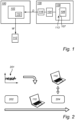
- FIG. 1 is an exemplary system diagram of a computer system 100 comprising processing circuitry 102.
- the processing circuitry 102 is configured to receive sensing data D from at least one sensor 104 arranged to detect sound waves emitted from electrical energy storage cells 106 of an electric energy storage system 108.
- the sensing data D indicates at least one characteristic of the sound waves.
- the data D are transmitted to the processing circuitry 102 via an optional transmitter 116.
- the electric energy storage system 108 may be arranged as a propulsion electrical energy storage system providing propulsion energy to a vehicle 109.
- the vehicle may be an electrical, hybrid, or plug-in hybrid vehicle comprising an electrical engine, wherein the electrical energy storage system provides energy to the electrical engine.
- the disclosure can equally well be applied to stationary applications marine applications.
- the electrical energy storage system comprises multiple cells 106 arranged in series and in parallel as is known in the art.
- Embodiments of the present disclosure is applicable to any type of electrical energy storage system, i.e., battery, that has liquid type of electrolyte, for example, Li-ion, lead-acid, etc.
- the processing circuitry 102 is configured to apply an algorithm 110 configured to predict a thermal runaway event by analyzing the sensing data D.
- the sensing data D may comprise time domain data of the soundwaves from which various properties can be derived including magnitude and frequency but also phase information and variations of these in time, all of which may be characteristics of the sound waves.
- the processing circuitry 102 is further configured to provide a message W if the outcome of the analysis is that a thermal runaway is predicted.
- the electronic message W may be provided to a control unit 112 of for example a vehicle or a stationary application.
- the message W may provide an instruction for the control unit 112 to activate cooling of the cells 106, or to control a switching circuitry to disconnect modules or cells 106, or other actions to prevent thermal runaway, and/or to transmit a message to an occupant via a user interface 114 to for example leave the vehicle.
- a user interface 114 of the vehicle may be an audio output device, a display or other visual indicators.
- the characteristics of the sound waves may be at least one of frequency spectrum, magnitude, phase, of the sound waves.
- any characteristic forming a fingerprint of a sound wave may be used in the algorithm for recognition of an upcoming thermal event.
- the sound waves 113 that are detected by the sensors 104 are generated from gas bubbles 107 in the electrical energy storage cells 106.
- the sound waves are caused by bubble vibration, rising, bursting, coalescence, collision and implosion of bubbles, and resonance of bubbles.
- the gas bubbles in the cells 106 change character due to that the material properties inside the cells 106 change. Stated otherwise, acoustic propagation from within the cell 106 is altered due to the changing material properties.
- the inventors thus realized that there is a sequence of events in a liquid electrical energy storage cell before it reaches thermal runaway, including electrolyte evaporation and gas production. These events produce gas bubbles 107 which generate pressure/acoustic waves 113 which include different range of frequencies.
- the early phase is mainly governed by low frequency events or infrasound.
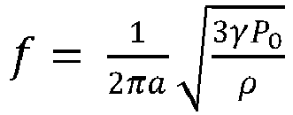
- Minnaert resonance is a phenomenon associated with a gas bubble pulsating at its natural frequency in a liquid.
- a is the radius of the bubble
- ⁇ is the polytropic efficiency
- P 0 is the pressure inside gas bubble
- ⁇ is the difference between the density of water and bulk density of the gas bubble.
- a sound wave As sound wave travels, its energy is slowly lost as heat because the molecules of the medium through which it is travelling collide against each other when they transmit the sound wave energy.
- the rate at which a sound wave is absorbed by a barrier depends on its frequency. If the barrier is wider than the wavelength of the sound wave, the sound wave will be absorbed. As a simple example, a sine wave at 20Hz has a wavelength of 17 meters and will therefore pass through most barriers.
- a bubble with wave frequency of 500 Hz inside salty water has wavelength of 3.12 meter. This wavelength will allow it to travel through existing barriers in an electrical energy storage system.
- the sensors 104 can detect bubbles with frequency of 5 kHz and diameter of 100 micrometer.
- a low frequency wave has the ability to travel long distances with little dissipation which leads to fewer required sensors per electrical energy storage pack.
- One source of the sound waves may thus be the bubble Minnaert resonance. Furthermore, another source may be bubbles bursting or collapsing which generates sound waves in the range of 0.5-5 kHz.
- the processing circuitry 102 is preferably further configured to predict the thermal runaway event by analyzing sound waves at characteristic frequencies of electrolyte boiling preceding a thermal runaway event.
- the frequencies may be below 5 kHz, such as in the range of 100 Hz-2 kHz, or 1 kHz to 2 kHz, or below 500 Hz.
- the algorithm 110 is a machine learning model trained to predict thermal runaway events from detection of acoustic waves generated from gas bubbles in electrical energy storage cells.
- Such machine learning model may be a supervised learning model 110 trained on acoustic data from test cells to create a fingerprint library of characteristic sounds of thermal runaway events.
- the computer system 100 is remotely located from the electrical energy storage system 100.
- the processing circuitry 102 may for example be part of a cloud-based system arranged on a server.
- the processing circuitry 102 is configured to receive the sensing data D wirelessly from a transmitter 116 connected to the sensors 104.
- the transmission technology may be for example Wifi, or any other available telecommunications technology such as mobile networks.
- FIG. 2 schematically illustrates a training procedure for a supervised learning model 110.
- Multiple recordings 201 such as hundreds or thousands or more, or acoustic waves generated by multiple test cells 202 prior to a thermal runaway event are made in a controlled environment such as a laboratory.
- the recordings are labelled as belonging to thermal runaway events and are fed to the supervised learning model 110 which creates a fingerprint library of the characteristic sounds prior to, i.e., several minutes prior to a thermal runaway event.
- the supervised model 110 is thus taught to classify new data as belonging to a near future thermal runaway event.
- the supervised model 110 is subsequently evaluated and tested on a validation set of cells 204.
- Supervised learning algorithms are in general advantageously used for applications where labelled training data is available.
- labeled recordings are available from prior recordings, where the data from libraries of recordings is labelled as thermal runaway event or not belonging to thermal runaway events.
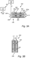
- FIG. 3A is a schematic side view and FIG. 3B is a schematic top view of a system 300 for detecting a thermal runaway in an electrical energy storage system 108 of a vehicle 109 or stationary application.
- the electrical energy storage system 108 comprises multiple electrical energy storage cells 106 distributed over more than one electrical energy storage pack 111.
- a set of sensors 302 are arranged to detect sound waves emitted from electrical energy storage cells 106 of the electrical energy storage system 108. As discussed above, the sensing data D indicating at least one characteristic of the sound waves. A greater number of sensors advantageously provides higher signal-to-noise ratio.
- the sensors 302 are here represented by an array of microphones 302 or accelerometers connected to the data collector 306, or transmitter, according to an example embodiment.
- the microphones 302 detect pressure/sound waves outside the cells 106 but that are generated in the cells 106.
- the microphones 302 transform the detected waves to electric impulses/signals and transmit the electric signals to the transmitter 306 via either hard wires or via wireless communication such as Bluetooth, Wi-Fi, etc.
- the transmitter 306 sends data D to the computer system 100, where the processing circuitry 102 is configured to apply the algorithm 110 to predict a thermal runaway event by analyzing the sensing data.
- a vehicle processing circuitry 112 is configured to provide a message.
- the processing circuitry may equally well be a or stationary application processing circuitry.
- the processing circuitry 112 receives a message W from the processing circuitry 102 with an instruction that a thermal runaway is predicted so that, in response, the processing circuitry 112 can provide the warning message M or an instruction I to perform preventive actions by for example cooling systems or switching circuitry of the electrical energy storage system 108.
- the warning message M or instruction I may be provided as early as 15 minutes before a thermal runaway event.
- sensors 302 are arranged in each electrical energy storage pack of the electrical energy storage system 108.
- the sensors 302 may be arranged inside a housing 308 of the electrical energy storage system 108, on the cells 106. That is the sensors 302 may be integrated within the electrical energy storage pack 111.
- the sensors are microphones 302 arranged inside a housing 308 of the electrical energy storage system 108 and preferably wirelessly 309 connected to the data collector 306 arranged outside the housing 308. That is the microphones 302 may be integrated within the electrical energy storage pack 111. However, as indicated, the microphones 302a may equally well be placed on the external outer surface 320 of the housing 308, thus not integrated inside the housing 308.
- the sensors may be accelerometers. Accelerometers can measure the structural vibrations of the cells caused by the gas bubbles inside the electrical energy storage pack 111. The analysis follows that used when the sensors are microphones.
- accelerometer or microphone may depend on for example the available space inside or on the surface of the electrical energy storage packs.
- FIG. 4A is a schematic side view and FIG. 4B is a schematic top view of a system 400 for detecting a thermal runaway in an electrical energy storage system 108..
- the sensors may be receivers 402 including horn shaped filters connected to waveguides 404.
- the receivers 402 may include an amplifier which amplifies the received sound before transmission to a data collector 406, here being a barometric sensor 406 at the other end of the waveguides 404.
- the barometric sensor 406 transforms detected and amplified sound waves to electrical impulses.
- data from the barometric sensor 406 are transmitted to the processing circuitry 102 of the computer system 100 configured to apply the algorithm 110 configured to predict a thermal runaway event by analyzing the sensing data.
- the waveguides 404 being in the form of pipes advantageously serves to filter out high frequency sound waves.
- the receivers 402 may be arranged inside the housing 308 or receivers 402a may be arranged on the outside surface 320 of the housing 308.
- Every electrical energy storage pack 111 may comprise a dedicated barometric sensor or a global barometric sensor may be used for multiple electrical energy storage packs 111.
- the barometric sensor may be an infrasound sensor, that is, a pressure wave sensor that is adapted to detect low frequency sound, such as below 5 kHz, below 1 kHz, below 500 Hz, or even below 100 Hz, or below 50 Hz.
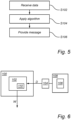
- FIG. 5 is a flow-chart of method steps according to embodiments of the present disclosure.
- step S102 receiving, by processing circuitry 102 of a computer system 100, sensing data D from at least one sensor 104 arranged to detect sound waves emitted from electrical energy storage cells 106 of an electrical energy storage system, the sensing data indicating at least one characteristic of the sound waves.
- the sound waves generated in the electrical energy storage cells 106 as result of gas bubble dynamics in the fluid of the cells 106 are received by the sensors 104, and data thereof is transmitted to the processing circuitry 102.
- step S 104 applying, by the processing circuitry 102, an algorithm 110 configured to predict a thermal runaway event by analyzing the sensing data.
- the algorithm is a machine learning model trained to predict thermal runaway events from detection of acoustic waves generated from gas bubbles in electrical energy storage cells.
- the machine learning model may be supervised learning model trained on acoustic data from test cells to create a fingerprint library of characteristic sounds of thermal runaway events.
- step S106 providing, by the processing circuitry 102, a warning message if the outcome of the analysis is that a thermal runaway is predicted.
- the analysis may be performed for sound waves at characteristic frequencies of electrolyte boiling preceding a thermal runaway event.
- frequencies may be below 5 kHz, such as in the range of 1-2 kHz, or 20 Hz to 500 Hz, to predict the thermal runaway event.
- FIG. 6 is another view of FIG. 1 , according to an example.
- FIG. 6 illustrates a computer system 100 comprising processing circuitry 102 configured to: receive sensing data D from at least one sensor 104 arranged to detect sound waves emitted from electrical energy storage cells 106 of an electrical energy storage system 108, the sensing data D indicating at least one characteristic of the sound waves.
- the processing circuitry 102 is configured to apply an algorithm 110 configured to predict a thermal runaway event by analyzing the sensing data D and provide a warning message W if the outcome of the analysis is that a thermal runaway is predicted.
- FIG. 7 is a flow chart of a method according to an example.
- step S202 receiving, by processing circuitry of a computer system, sensing data from at least one sensor arranged to detect sound waves emitted from electrical energy storage cells of an electrical energy storage system, the sensing data indicating at least one characteristic of the sound waves.
- step S204 applying, by the processing circuitry, an algorithm configured to predict a thermal runaway event by analyzing the sensing data.
- step S206 providing, by the processing circuitry, a warning message if the outcome of the analysis is that a thermal runaway is predicted.
- FIG. 8 is a schematic diagram of a computer system 800 for implementing examples disclosed herein.
- the computer system 800 is adapted to execute instructions from a computer-readable medium to perform these and/or any of the functions or processing described herein.
- the computer system 800 may be connected (e.g., networked) to other machines in a LAN, an intranet, an extranet, or the Internet. While only a single device is illustrated, the computer system 800 may include any collection of devices that individually or jointly execute a set (or multiple sets) of instructions to perform any one or more of the methodologies discussed herein.
- any reference in the disclosure and/or claims to a computer system, computing system, computer device, computing device, control system, control unit, electronic control unit (ECU), processor device, processing circuitry, etc. includes reference to one or more such devices to individually or jointly execute a set (or multiple sets) of instructions to perform any one or more of the methodologies discussed herein.
- control system may include a single control unit or a plurality of control units connected or otherwise communicatively coupled to each other, such that any performed function may be distributed between the control units as desired.
- such devices may communicate with each other or other devices by various system architectures, such as directly or via a Controller Area Network (CAN) bus, etc.
- CAN Controller Area Network
- the computer system 800 may comprise at least one computing device or electronic device capable of including firmware, hardware, and/or executing software instructions to implement the functionality described herein.
- the computer system 800 may include processing circuitry 802 (e.g., processing circuitry including one or more processor devices or control units), a memory 804 , and a system bus 806 .
- the computer system 800 may include at least one computing device having the processing circuitry 802 .
- the system bus 806 provides an interface for system components including, but not limited to, the memory 804 and the processing circuitry 802 .
- the processing circuitry 802 may include any number of hardware components for conducting data or signal processing or for executing computer code stored in memory 804 .
- the processing circuitry 802 may, for example, include a general-purpose processor, an application specific processor, a Digital Signal Processor (DSP), an Application Specific Integrated Circuit (ASIC), a Field Programmable Gate Array (FPGA), a circuit containing processing components, a group of distributed processing components, a group of distributed computers configured for processing, or other programmable logic device, discrete gate or transistor logic, discrete hardware components, or any combination thereof designed to perform the functions described herein.
- the processing circuitry 802 may further include computer executable code that controls operation of the programmable device.
- the system bus 806 may be any of several types of bus structures that may further interconnect to a memory bus (with or without a memory controller), a peripheral bus, and/or a local bus using any of a variety of bus architectures.
- the memory 804 may be one or more devices for storing data and/or computer code for completing or facilitating methods described herein.
- the memory 804 may include database components, object code components, script components, or other types of information structure for supporting the various activities herein. Any distributed or local memory device may be utilized with the systems and methods of this description.
- the memory 804 may be communicably connected to the processing circuitry 802 (e.g., via a circuit or any other wired, wireless, or network connection) and may include computer code for executing one or more processes described herein.
- the memory 804 may include non-volatile memory 808 (e.g., read-only memory (ROM), erasable programmable read-only memory (EPROM), electrically erasable programmable read-only memory (EEPROM), etc.), and volatile memory 810 (e.g., random-access memory (RAM)), or any other medium which can be used to carry or store desired program code in the form of machine-executable instructions or data structures and which can be accessed by a computer or other machine with processing circuitry 802 .
- a basic input/output system (BIOS) 812 may be stored in the non-volatile memory 808 and can include the basic routines that help to transfer information between elements within the computer system 800 .
- BIOS basic input/output system
- the computer system 800 may further include or be coupled to a non-transitory computer-readable storage medium such as the storage device 814 , which may comprise, for example, an internal or external hard disk drive (HDD) (e.g., enhanced integrated drive electronics (EIDE) or serial advanced technology attachment (SATA)), HDD (e.g., EIDE or SATA) for storage, flash memory, or the like.
- HDD enhanced integrated drive electronics
- SATA serial advanced technology attachment
- the storage device 814 and other drives associated with computer-readable media and computer-usable media may provide non-volatile storage of data, data structures, computer-executable instructions, and the like.
- Computer-code which is hard or soft coded may be provided in the form of one or more modules.
- the module(s) can be implemented as software and/or hard-coded in circuitry to implement the functionality described herein in whole or in part.
- the modules may be stored in the storage device 814 and/or in the volatile memory 810 , which may include an operating system 816 and/or one or more program modules 818 .
- All or a portion of the examples disclosed herein may be implemented as a computer program 820 stored on a transitory or non-transitory computer-usable or computer-readable storage medium (e.g., single medium or multiple media), such as the storage device 814 , which includes complex programming instructions (e.g., complex computer-readable program code) to cause the processing circuitry 802 to carry out actions described herein.
- the computer-readable program code of the computer program 820 can comprise software instructions for implementing the functionality of the examples described herein when executed by the processing circuitry 802 .
- the storage device 814 may be a computer program product (e.g., readable storage medium) storing the computer program 820 thereon, where at least a portion of a computer program 820 may be loadable (e.g., into a processor) for implementing the functionality of the examples described herein when executed by the processing circuitry 802 .
- the processing circuitry 802 may serve as a controller or control system for the computer system 800 that is to implement the functionality described herein.
- the computer system 800 may include an input device interface 822 configured to receive input and selections to be communicated to the computer system 800 when executing instructions, such as from a keyboard, mouse, touch-sensitive surface, etc. Such input devices may be connected to the processing circuitry 802 through the input device interface 822 coupled to the system bus 806 but can be connected through other interfaces, such as a parallel port, an Institute of Electrical and Electronic Engineers (IEEE) 1394 serial port, a Universal Serial Bus (USB) port, an IR interface, and the like.
- the computer system 800 may include an output device interface 824 configured to forward output, such as to a display, a video display unit (e.g., a liquid crystal display (LCD) or a cathode ray tube (CRT)).
- the computer system 800 may include a communications interface 826 suitable for communicating with a network as appropriate or desired.
- Example 1 A computer system comprising processing circuitry configured to: receive sensing data from at least one sensor arranged to detect sound waves emitted from electrical energy storage cells of an electrical energy storage system, the sensing data indicating at least one characteristic of the sound waves, apply an algorithm configured to predict a thermal runaway event by analyzing the sensing data, provide a message if the outcome of the analysis is that a thermal runaway is predicted.
- Example 2 The computer system of example 1, wherein the algorithm is a machine learning model trained to predict thermal runaway events from detection of acoustic waves generated from gas bubbles in electrical energy storage cells.
- Example 3 The computer system of example 2, the machine learning model is a supervised learning model trained on acoustic data from test cells to create a fingerprint library of characteristic sounds of thermal runaway events.
- Example 4 The computer system of any of examples 1-3, wherein the processing circuitry is further configured to: predict the thermal runaway event by analyze sound waves at characteristic frequencies of electrolyte boiling preceding a thermal runaway event.
- Example 5 The computer system of any of examples 1-4, wherein the processing circuitry is configured to receive the sensing data wirelessly from a transmitter connected to the sensors.
- Example 6 The computer system of any of examples 1-5, wherein sensing data is received from multiple sensors.
- Example 7 The computer system of any of examples 1-6, wherein the sensors in the electrical energy storage system are at least one of microphones, horn filters connected to waveguides, or accelerometers.
- Example 8 A computer-implemented method, comprising: receiving, by processing circuitry of a computer system, sensing data from at least one sensor arranged to detect sound waves emitted from electrical energy storage cells of an electrical energy storage system, the sensing data indicating at least one characteristic of the sound waves, applying, by the processing circuitry, an algorithm configured to predict a thermal runaway event by analyzing the sensing data, providing, by the processing circuitry, a message if the outcome of the analysis is that a thermal runaway is predicted.
- Example 9 The computer-implemented method of example 8, wherein the algorithm is a machine learning model trained to predict thermal runaway events from detection of acoustic waves generated from gas bubbles in electrical energy storage cells.
- Example 10 The computer-implemented method of example 9, the machine learning model is a supervised learning model trained on acoustic data from test cells to create a fingerprint library of characteristic sounds of thermal runaway events.
- Example 11 The computer-implemented method of any of examples 8-10, comprising: analyzing, by the processing circuitry, sound waves at characteristic frequencies of electrolyte boiling preceding a thermal runaway event, to predict the thermal runaway event.
- Example 12 The computer-implemented method of any of examples 8-11, comprising:
- the processing circuitry receiving, by the processing circuitry, the sensing data wirelessly from a transmitter connected to the sensors.
- Example 13 The computer-implemented method of any of examples 8-12, wherein sensing data is received from multiple sensors connected to a barometric sensor configured to transmit the sensing data to the processing circuitry.
- Example 14 The computer-implemented method of any of examples 8-13, wherein the sensors in the electrical energy storage system are at least one of microphones, horn filters connected to waveguides, or accelerometers.
- Example 15 A computer program product comprising program code for performing, when executed by the processing circuitry, the method of any of examples 8-14.
- Example 16 A non-transitory computer-readable storage medium comprising instructions, which when executed by the processing circuitry, cause the processing circuitry to perform the method of any of examples 8-14.
- Example 17 A system for detecting a thermal runaway in an electrical energy storage system of a vehicle, the system comprising: a set of sensors arranged to detect sound waves emitted from electrical energy storage cells of the electrical energy storage system, the sensing data indicating at least one characteristic of the sound waves, data collector configured to receive sensing signals from the sensors and transmit sensing data to processing circuitry configured to apply an algorithm configured to predict a thermal runaway event by analyzing the sensing data, and a vehicle processing circuitry configured to provide a message if the outcome of the analysis is that a thermal runaway is predicted.
- Example 18 The system of example 17, comprising multiple arrays of sensors in each electrical energy storage pack of the electrical energy storage system.
- Example 19 The system of any of examples 18-17, wherein the sensors are microphones arranged inside a housing of the electrical energy storage system wirelessly connected to the data collector arranged outside the housing, or the sensors are horn filters connected to waveguides that guide the sound waves to a barometric sensor outside the housing, or accelerometers.
- the sensors are microphones arranged inside a housing of the electrical energy storage system wirelessly connected to the data collector arranged outside the housing, or the sensors are horn filters connected to waveguides that guide the sound waves to a barometric sensor outside the housing, or accelerometers.
- Example 20 A vehicle comprising the system of any of examples 17-19.
- Relative terms such as “below” or “above” or “upper” or “lower” or “horizontal” or “vertical” may be used herein to describe a relationship of one element to another element as illustrated in the Figures. It will be understood that these terms and those discussed above are intended to encompass different orientations of the device in addition to the orientation depicted in the Figures. It will be understood that when an element is referred to as being “connected” or “coupled” to another element, it can be directly connected or coupled to the other element, or intervening elements may be present. In contrast, when an element is referred to as being “directly connected” or “directly coupled” to another element, there are no intervening elements present.
Landscapes
- Engineering & Computer Science (AREA)
- Physics & Mathematics (AREA)
- General Physics & Mathematics (AREA)
- Life Sciences & Earth Sciences (AREA)
- Chemical & Material Sciences (AREA)
- General Health & Medical Sciences (AREA)
- Pathology (AREA)
- Analytical Chemistry (AREA)
- Biochemistry (AREA)
- Health & Medical Sciences (AREA)
- Immunology (AREA)
- Theoretical Computer Science (AREA)
- Software Systems (AREA)
- Evolutionary Computation (AREA)
- Artificial Intelligence (AREA)
- Power Engineering (AREA)
- Data Mining & Analysis (AREA)
- Acoustics & Sound (AREA)
- Computer Vision & Pattern Recognition (AREA)
- Mathematical Physics (AREA)
- General Engineering & Computer Science (AREA)
- Computing Systems (AREA)
- Medical Informatics (AREA)
- Manufacturing & Machinery (AREA)
- Mechanical Engineering (AREA)
- Transportation (AREA)
- Sustainable Energy (AREA)
- Sustainable Development (AREA)
- General Chemical & Material Sciences (AREA)
- Electrochemistry (AREA)
- Chemical Kinetics & Catalysis (AREA)
- Signal Processing (AREA)
- Investigating Or Analyzing Materials By The Use Of Ultrasonic Waves (AREA)
- Arrangements For Transmission Of Measured Signals (AREA)
- Measurement Of Mechanical Vibrations Or Ultrasonic Waves (AREA)
- Secondary Cells (AREA)
Abstract
Description
- The disclosure relates generally to safety in electrical energy storage systems. In particular aspects, the disclosure relates to passive detection of thermal runaway using acoustic waves. The disclosure can be applied to heavy-duty vehicles, such as trucks, buses, and construction equipment, among other vehicle types. Furthermore, the disclosure can equally well be applied to stationary applications and marine applications. Although the disclosure may be described with respect to a particular vehicle, the disclosure is not restricted to any particular vehicle.
- Thermal runaway events in electrical energy storage systems of vehicles are hazardous for occupants of the vehicle and to surrounding people. Furthermore, thermal runaway events may cause damage to the vehicle and potentially also to objects near the vehicle.
- Current safety features implemented on electrical energy storage systems are typically heavily dependent on temperature sensors or thermocouples arranged on the internal structures or on the cells of the electrical energy storage systems. However, for an effective warning system, the warning should come sufficiently early so that preventive measures or safety measures can be applied well before the thermal runaway event actually occurs and excessive heat is developed.
- According to a first aspect of the disclosure, there is provided a computer system comprising processing circuitry configured to: receive sensing data from at least one sensor arranged to detect sound waves emitted from electrical energy storage cells of an electrical energy storage system, the sensing data indicating at least one characteristic of the sound waves, apply an algorithm configured to predict a thermal runaway event by analyzing the sensing data, provide a message if the outcome of the analysis is that a thermal runaway is predicted.
- The first aspect of the disclosure may seek to improve the detection of thermal runaway events in an electrical energy storage system. A technical benefit may include earlier detection which allows more time and opportunity to take measures in response to the predicted thermal runaway event.
- Optionally in some examples, including in at least one preferred example, the algorithm may be a machine learning model trained to predict thermal runaway events from detection of acoustic waves generated from gas bubbles in electrical energy storage cells. A technical benefit may include improved ability to detect thermal runaway events earlier and with improved accuracy.
- Optionally in some examples, including in at least one preferred example, the machine learning model may be a supervised learning model trained on acoustic data from test cells to create a fingerprint library of characteristic sounds of thermal runaway events. A technical benefit may include an improved model for predicting the thermal runaway event.
- Optionally in some examples, including in at least one preferred example, the processing circuitry may be further configured to: predict the thermal runaway event by analyzing sound waves at characteristic frequencies of electrolyte boiling preceding a thermal runaway event. "Preceding" a thermal runaway is meant near or just before as in several minutes, e.g., 10-15 minutes before a thermal runaway event.
- For example, the processing circuitry may be configured to analyze sound waves at frequencies below 5 kHz, such as in the range of 1-2 kHz, or below 500 Hz. A technical benefit may include the ability to detect sound waves specifically generated from gas bubbles in the electrical energy storage cells. Thus, the algorithm may filter out frequencies that are not relevant for detecting thermal runaway events through analysis of acoustic dynamics of gas bubbles. The source of the sound waves is one or more of bubble formation, bubble movement, and bubble collapse and resonance thereof.
- Optionally in some examples, including in at least one preferred example, the processing circuitry may be configured to receive the sensing data wirelessly from a transmitter connected to the sensors. A technical benefit may include less complicated integration since the use of hardwires is reduced or eliminated.
- Optionally in some examples, including in at least one preferred example, sensing data may be received from multiple sensors. A technical benefit may include improved detection since multiple sensors are used that can detected sound waves from more than one location of the electrical energy storage system.
- Optionally in some examples, including in at least one preferred example, the sensors in the electrical energy storage system may be at least one of microphones, horn filters connected to waveguides, or accelerometers.
- According to a second aspect of the disclosure, there is provided a computer-implemented method, comprising: receiving, by processing circuitry of a computer system, sensing data from at least one sensor arranged to detect sound waves emitted from electrical energy storage cells of an electrical energy storage system, the sensing data indicating at least one characteristic of the sound waves, applying, by the processing circuitry, an algorithm configured to predict a thermal runaway event by analyzing the sensing data, providing, by the processing circuitry, a message if the outcome of the analysis is that a thermal runaway is predicted.
- The second aspect of the disclosure may seek to improve the detection of thermal runaway events in an electrical energy storage system. A technical benefit may include earlier detection which gives more time and opportunity to take measures in response to the predicted thermal runaway event.
- Optionally in some examples, including in at least one preferred example, the algorithm is a machine learning model trained to predict thermal runaway events from detection of acoustic waves generated from gas bubbles in electrical energy storage cells. A technical benefit may include improved ability to detect thermal runaway events earlier and with improved accuracy.
- Optionally in some examples, including at least one preferred example, the machine learning model is a supervised learning model trained on acoustic data from test cells to create a fingerprint library of characteristic sounds of thermal runaway events. A technical benefit may include an improved model for predicting the thermal runaway event.
- Optionally in some examples, including in at least one preferred example, the method may comprise: analyzing, by the processing circuitry, sound waves at characteristic frequencies of electrolyte boiling preceding a thermal runaway event. For example, the processing circuitry may be configured to analyze sound waves at frequencies below 5 kHz, such as in the range of 1-2 kHz, or below 500 Hz, to predict the thermal runaway event. A technical benefit may include the ability to detect sound waves specifically generated from gas bubbles in the electrical energy storage cells. Thus, the algorithm may target frequencies that are most relevant for predicting thermal runaway events through detection of gas bubbles.
- Optionally in some examples, including in at least one preferred example, the method may comprise: receiving, by the processing circuitry, the sensing data wirelessly from a transmitter connected to the sensors. A technical benefit may include less complicated integration since the use of hardwires is reduced or eliminated.
- Optionally in some examples, including in at least one preferred example, sensing data may be received from multiple sensors configured to transmit the sensing data to the processing circuitry. The sensors each detects sound waves and transforms them to electric signals. The sensors may be configured to detect infrasound.
- Optionally in some examples, including in at least one preferred example, the sensors may be at least one of microphones, horn filters connected to waveguides, or accelerometers. Accelerometers provide a relatively cost-efficient sensor solution.
- There is further provided a computer program product comprising program code for performing, when executed by the processing circuitry, the method of the second aspect.
- There is further provided a non-transitory computer-readable storage medium comprising instructions, which when executed by the processing circuitry, cause the processing circuitry to perform the method of the second aspect.
- According to a third aspect of the disclosure, there is provided a system for detecting a thermal runaway in an electrical energy storage system of a vehicle, the system comprising: a set of sensors arranged to detect sound waves emitted from electrical energy storage cells of the electrical energy storage system, the sensing data indicating at least one characteristic of the sound waves, data collector configured to receive sensing signals from the sensors and transmit sensing data to processing circuitry configured to apply an algorithm configured to predict a thermal runaway event by analyzing the sensing data, and a vehicle processing circuitry configured to provide a message if the outcome of the analysis is that a thermal runaway is predicted.
- The third aspect of the disclosure may seek to improve the detection of thermal runaway events in an electrical energy storage system. A technical benefit may include earlier detection which gives more time and opportunity to take measures in response to the predicted thermal runaway event.
- Optionally in some examples, including in at least one preferred example, the system may comprise multiple arrays of sensors in each electrical energy storage pack of the electrical energy storage system. A technical benefit may include more accurate detection of sound waves from multiple locations of the electrical energy storage system, thereby improve prediction of thermal runaway events.
- Optionally in some examples, including in at least one preferred example, the sensors may be microphones arranged inside a housing of the electrical energy storage system wirelessly connected to the data collector arranged outside the housing, or the sensors are horn filters connected to waveguides that guide the sound waves to a barometric sensor outside the housing, or accelerometers.
- There is further provided a vehicle comprising the system of the third aspect.
- The disclosed aspects, examples (including any preferred examples), and/or accompanying claims may be suitably combined with each other as would be apparent to anyone of ordinary skill in the art. Additional features and advantages are disclosed in the following description, claims, and drawings, and in part will be readily apparent therefrom to those skilled in the art or recognized by practicing the disclosure as described herein.
- There are also disclosed herein computer systems, control units, code modules, computer-implemented methods, computer readable media, and computer program products associated with the above discussed technical benefits.
-
-
FIG. 1 is an exemplary system diagram of a computer system according to an example. -
FIG. 2 schematically illustrates a training procedure for a supervised learning model according to an example. -
FIG. 3A is a schematic side view of a system according to one example embodiment. -
FIG. 3B is a schematic top view of a system according to one example embodiment. -
FIG. 4A is a schematic side view of a system according to one example embodiment. -
FIG. 4B is a schematic top view of a system according to one example embodiment. -
FIG. 5 is a flow-chart of method steps according to one example embodiment. -
FIG. 6 is another view ofFIG. 1 , according to an example. -
FIG. 7 is a flow chart of an exemplary method according to an example. -
FIG. 8 is a schematic diagram of an exemplary computer system for implementing examples disclosed herein, according to an example. - The detailed description set forth below provides information and examples of the disclosed technology with sufficient detail to enable those skilled in the art to practice the disclosure.
- During a thermal runaway event in electrical energy storage devices such as batteries, temperatures exceeding 1000°C may occur in the cell of the battery. In addition, high amounts of flammable and harmful gases are typically released. The heat developed in one cell during a thermal runaway event can trigger a thermal runaway event in surrounding cells of the battery thereby leading to thermal runaway propagation which may have severe consequences in terms of damage and injury. Although a thermal runaway event can be detected using for example temperature sensors, the detection may be too late, and an escalating thermal runaway may already have been initiated. Therefore, it is desirable to detect or predict a thermal runaway event earlier so that preventive measures can be taken as soon as possible to reduce the risk of an escalating thermal runaway.
- To address the above discussed problem, the inventors realized to measure pressure or sound waves generated in the cells of the electric energy storage system as will be laid out in more detail below.
-
FIG. 1 is an exemplary system diagram of acomputer system 100 comprisingprocessing circuitry 102. - The
processing circuitry 102 is configured to receive sensing data D from at least onesensor 104 arranged to detect sound waves emitted from electricalenergy storage cells 106 of an electricenergy storage system 108. The sensing data D indicates at least one characteristic of the sound waves. The data D are transmitted to theprocessing circuitry 102 via anoptional transmitter 116. - The electric
energy storage system 108 may be arranged as a propulsion electrical energy storage system providing propulsion energy to avehicle 109. The vehicle may be an electrical, hybrid, or plug-in hybrid vehicle comprising an electrical engine, wherein the electrical energy storage system provides energy to the electrical engine. Furthermore, the disclosure can equally well be applied to stationary applications marine applications. - The electrical energy storage system comprises
multiple cells 106 arranged in series and in parallel as is known in the art. - Embodiments of the present disclosure is applicable to any type of electrical energy storage system, i.e., battery, that has liquid type of electrolyte, for example, Li-ion, lead-acid, etc.
- The
processing circuitry 102 is configured to apply analgorithm 110 configured to predict a thermal runaway event by analyzing the sensing data D. The sensing data D may comprise time domain data of the soundwaves from which various properties can be derived including magnitude and frequency but also phase information and variations of these in time, all of which may be characteristics of the sound waves. - The
processing circuitry 102 is further configured to provide a message W if the outcome of the analysis is that a thermal runaway is predicted. The electronic message W may be provided to acontrol unit 112 of for example a vehicle or a stationary application. The message W may provide an instruction for thecontrol unit 112 to activate cooling of thecells 106, or to control a switching circuitry to disconnect modules orcells 106, or other actions to prevent thermal runaway, and/or to transmit a message to an occupant via a user interface 114 to for example leave the vehicle. A user interface 114 of the vehicle may be an audio output device, a display or other visual indicators. - The characteristics of the sound waves may be at least one of frequency spectrum, magnitude, phase, of the sound waves. Generally, any characteristic forming a fingerprint of a sound wave may be used in the algorithm for recognition of an upcoming thermal event.
- The
sound waves 113 that are detected by thesensors 104 are generated fromgas bubbles 107 in the electricalenergy storage cells 106. The sound waves are caused by bubble vibration, rising, bursting, coalescence, collision and implosion of bubbles, and resonance of bubbles. As a cell approaches a thermal runaway event, the gas bubbles in thecells 106 change character due to that the material properties inside thecells 106 change. Stated otherwise, acoustic propagation from within thecell 106 is altered due to the changing material properties. - The inventors thus realized that there is a sequence of events in a liquid electrical energy storage cell before it reaches thermal runaway, including electrolyte evaporation and gas production. These events produce
gas bubbles 107 which generate pressure/acoustic waves 113 which include different range of frequencies. However, the early phase is mainly governed by low frequency events or infrasound. - One of the sources of sound is the so-called Minnaert resonance which is a phenomenon associated with a gas bubble pulsating at its natural frequency in a liquid. Technically the gas bubble frequency, f, inside liquid is calculated by,
- Where a is the radius of the bubble, γ is the polytropic efficiency, P 0 is the pressure inside gas bubble and ρ is the difference between the density of water and bulk density of the gas bubble. For a single bubble in electrolyte and

- As sound wave travels, its energy is slowly lost as heat because the molecules of the medium through which it is travelling collide against each other when they transmit the sound wave energy. The rate at which a sound wave is absorbed by a barrier depends on its frequency. If the barrier is wider than the wavelength of the sound wave, the sound wave will be absorbed. As a simple example, a sine wave at 20Hz has a wavelength of 17 meters and will therefore pass through most barriers.
- As an example, a bubble with wave frequency of 500 Hz inside salty water has wavelength of 3.12 meter. This wavelength will allow it to travel through existing barriers in an electrical energy storage system. For most electrical
energy storage systems 108, the dimensions of thecell 106 and surrounding components, thesensors 104 can detect bubbles with frequency of 5 kHz and diameter of 100 micrometer. Generally speaking, a low frequency wave has the ability to travel long distances with little dissipation which leads to fewer required sensors per electrical energy storage pack. - One source of the sound waves may thus be the bubble Minnaert resonance. Furthermore, another source may be bubbles bursting or collapsing which generates sound waves in the range of 0.5-5 kHz.
- The
processing circuitry 102 is preferably further configured to predict the thermal runaway event by analyzing sound waves at characteristic frequencies of electrolyte boiling preceding a thermal runaway event. The frequencies may be below 5 kHz, such as in the range of 100 Hz-2 kHz, or 1 kHz to 2 kHz, or below 500 Hz. - Preferably, the
algorithm 110 is a machine learning model trained to predict thermal runaway events from detection of acoustic waves generated from gas bubbles in electrical energy storage cells. Such machine learning model may be asupervised learning model 110 trained on acoustic data from test cells to create a fingerprint library of characteristic sounds of thermal runaway events. - In some possible implementations, the
computer system 100 is remotely located from the electricalenergy storage system 100. Theprocessing circuitry 102 may for example be part of a cloud-based system arranged on a server. Thus, theprocessing circuitry 102 is configured to receive the sensing data D wirelessly from atransmitter 116 connected to thesensors 104. The transmission technology may be for example Wifi, or any other available telecommunications technology such as mobile networks. -
FIG. 2 schematically illustrates a training procedure for asupervised learning model 110.Multiple recordings 201, such as hundreds or thousands or more, or acoustic waves generated bymultiple test cells 202 prior to a thermal runaway event are made in a controlled environment such as a laboratory. The recordings are labelled as belonging to thermal runaway events and are fed to thesupervised learning model 110 which creates a fingerprint library of the characteristic sounds prior to, i.e., several minutes prior to a thermal runaway event. Thesupervised model 110 is thus taught to classify new data as belonging to a near future thermal runaway event. Thesupervised model 110 is subsequently evaluated and tested on a validation set ofcells 204. - Supervised learning algorithms are in general advantageously used for applications where labelled training data is available. For the present disclosure, labeled recordings are available from prior recordings, where the data from libraries of recordings is labelled as thermal runaway event or not belonging to thermal runaway events.
-
FIG. 3A is a schematic side view andFIG. 3B is a schematic top view of asystem 300 for detecting a thermal runaway in an electricalenergy storage system 108 of avehicle 109 or stationary application. The electricalenergy storage system 108 comprises multiple electricalenergy storage cells 106 distributed over more than one electricalenergy storage pack 111. - A set of
sensors 302 are arranged to detect sound waves emitted from electricalenergy storage cells 106 of the electricalenergy storage system 108. As discussed above, the sensing data D indicating at least one characteristic of the sound waves. A greater number of sensors advantageously provides higher signal-to-noise ratio. - The
sensors 302 are here represented by an array ofmicrophones 302 or accelerometers connected to thedata collector 306, or transmitter, according to an example embodiment. - The
microphones 302 detect pressure/sound waves outside thecells 106 but that are generated in thecells 106. Themicrophones 302 transform the detected waves to electric impulses/signals and transmit the electric signals to thetransmitter 306 via either hard wires or via wireless communication such as Bluetooth, Wi-Fi, etc. Thetransmitter 306 sends data D to thecomputer system 100, where theprocessing circuitry 102 is configured to apply thealgorithm 110 to predict a thermal runaway event by analyzing the sensing data. - If the outcome of the analysis performed by the
processing circuitry 102 is that a thermal runaway is predicted, avehicle processing circuitry 112 is configured to provide a message. The processing circuitry may equally well be a or stationary application processing circuitry. Theprocessing circuitry 112 receives a message W from theprocessing circuitry 102 with an instruction that a thermal runaway is predicted so that, in response, theprocessing circuitry 112 can provide the warning message M or an instruction I to perform preventive actions by for example cooling systems or switching circuitry of the electricalenergy storage system 108. Using the herein proposed analysis, the warning message M or instruction I may be provided as early as 15 minutes before a thermal runaway event. - Preferably, multiple arrays of
sensors 302 are arranged in each electrical energy storage pack of the electricalenergy storage system 108. Thesensors 302 may be arranged inside ahousing 308 of the electricalenergy storage system 108, on thecells 106. That is thesensors 302 may be integrated within the electricalenergy storage pack 111. - In this
system 300, the sensors aremicrophones 302 arranged inside ahousing 308 of the electricalenergy storage system 108 and preferably wirelessly 309 connected to thedata collector 306 arranged outside thehousing 308. That is themicrophones 302 may be integrated within the electricalenergy storage pack 111. However, as indicated, themicrophones 302a may equally well be placed on the externalouter surface 320 of thehousing 308, thus not integrated inside thehousing 308. - In some embodiments the sensors may be accelerometers. Accelerometers can measure the structural vibrations of the cells caused by the gas bubbles inside the electrical
energy storage pack 111. The analysis follows that used when the sensors are microphones. - The choice of accelerometer or microphone may depend on for example the available space inside or on the surface of the electrical energy storage packs.
-
FIG. 4A is a schematic side view andFIG. 4B is a schematic top view of asystem 400 for detecting a thermal runaway in an electricalenergy storage system 108.. - In this embodiment, the sensors may be
receivers 402 including horn shaped filters connected to waveguides 404. Further, thereceivers 402 may include an amplifier which amplifies the received sound before transmission to adata collector 406, here being abarometric sensor 406 at the other end of thewaveguides 404. Thebarometric sensor 406 transforms detected and amplified sound waves to electrical impulses. Next, data from thebarometric sensor 406 are transmitted to theprocessing circuitry 102 of thecomputer system 100 configured to apply thealgorithm 110 configured to predict a thermal runaway event by analyzing the sensing data. - The
waveguides 404 being in the form of pipes advantageously serves to filter out high frequency sound waves. - The
receivers 402 may be arranged inside thehousing 308 orreceivers 402a may be arranged on theoutside surface 320 of thehousing 308. - Every electrical
energy storage pack 111 may comprise a dedicated barometric sensor or a global barometric sensor may be used for multiple electrical energy storage packs 111. The barometric sensor may be an infrasound sensor, that is, a pressure wave sensor that is adapted to detect low frequency sound, such as below 5 kHz, below 1 kHz, below 500 Hz, or even below 100 Hz, or below 50 Hz. -
FIG. 5 is a flow-chart of method steps according to embodiments of the present disclosure. - In step S102, receiving, by processing
circuitry 102 of acomputer system 100, sensing data D from at least onesensor 104 arranged to detect sound waves emitted from electricalenergy storage cells 106 of an electrical energy storage system, the sensing data indicating at least one characteristic of the sound waves. In other words, the sound waves generated in the electricalenergy storage cells 106 as result of gas bubble dynamics in the fluid of thecells 106 are received by thesensors 104, and data thereof is transmitted to theprocessing circuitry 102. - In
step S 104 applying, by theprocessing circuitry 102, analgorithm 110 configured to predict a thermal runaway event by analyzing the sensing data. Preferably, the algorithm is a machine learning model trained to predict thermal runaway events from detection of acoustic waves generated from gas bubbles in electrical energy storage cells. The machine learning model may be supervised learning model trained on acoustic data from test cells to create a fingerprint library of characteristic sounds of thermal runaway events. - In step S106, providing, by the
processing circuitry 102, a warning message if the outcome of the analysis is that a thermal runaway is predicted. - In order to filter out sound dynamics that are not relevant for prediction of thermal runaway events from gas bubble dynamics, the analysis may be performed for sound waves at characteristic frequencies of electrolyte boiling preceding a thermal runaway event. For example, such frequencies may be below 5 kHz, such as in the range of 1-2 kHz, or 20 Hz to 500 Hz, to predict the thermal runaway event.
-
FIG. 6 is another view ofFIG. 1 , according to an example.FIG. 6 illustrates acomputer system 100 comprisingprocessing circuitry 102 configured to: receive sensing data D from at least onesensor 104 arranged to detect sound waves emitted from electricalenergy storage cells 106 of an electricalenergy storage system 108, the sensing data D indicating at least one characteristic of the sound waves. - The
processing circuitry 102 is configured to apply analgorithm 110 configured to predict a thermal runaway event by analyzing the sensing data D and provide a warning message W if the outcome of the analysis is that a thermal runaway is predicted. -
FIG. 7 is a flow chart of a method according to an example. - In step S202 receiving, by processing circuitry of a computer system, sensing data from at least one sensor arranged to detect sound waves emitted from electrical energy storage cells of an electrical energy storage system, the sensing data indicating at least one characteristic of the sound waves.
- In step S204 applying, by the processing circuitry, an algorithm configured to predict a thermal runaway event by analyzing the sensing data.
- In step S206 providing, by the processing circuitry, a warning message if the outcome of the analysis is that a thermal runaway is predicted.
-
FIG. 8 is a schematic diagram of acomputer system 800 for implementing examples disclosed herein. Thecomputer system 800 is adapted to execute instructions from a computer-readable medium to perform these and/or any of the functions or processing described herein. Thecomputer system 800 may be connected (e.g., networked) to other machines in a LAN, an intranet, an extranet, or the Internet. While only a single device is illustrated, thecomputer system 800 may include any collection of devices that individually or jointly execute a set (or multiple sets) of instructions to perform any one or more of the methodologies discussed herein. Accordingly, any reference in the disclosure and/or claims to a computer system, computing system, computer device, computing device, control system, control unit, electronic control unit (ECU), processor device, processing circuitry, etc., includes reference to one or more such devices to individually or jointly execute a set (or multiple sets) of instructions to perform any one or more of the methodologies discussed herein. For example, control system may include a single control unit or a plurality of control units connected or otherwise communicatively coupled to each other, such that any performed function may be distributed between the control units as desired. Further, such devices may communicate with each other or other devices by various system architectures, such as directly or via a Controller Area Network (CAN) bus, etc. - The
computer system 800 may comprise at least one computing device or electronic device capable of including firmware, hardware, and/or executing software instructions to implement the functionality described herein. Thecomputer system 800 may include processing circuitry 802 (e.g., processing circuitry including one or more processor devices or control units), amemory 804, and asystem bus 806. Thecomputer system 800 may include at least one computing device having theprocessing circuitry 802. Thesystem bus 806 provides an interface for system components including, but not limited to, thememory 804 and theprocessing circuitry 802. Theprocessing circuitry 802 may include any number of hardware components for conducting data or signal processing or for executing computer code stored inmemory 804. Theprocessing circuitry 802 may, for example, include a general-purpose processor, an application specific processor, a Digital Signal Processor (DSP), an Application Specific Integrated Circuit (ASIC), a Field Programmable Gate Array (FPGA), a circuit containing processing components, a group of distributed processing components, a group of distributed computers configured for processing, or other programmable logic device, discrete gate or transistor logic, discrete hardware components, or any combination thereof designed to perform the functions described herein. Theprocessing circuitry 802 may further include computer executable code that controls operation of the programmable device. - The
system bus 806 may be any of several types of bus structures that may further interconnect to a memory bus (with or without a memory controller), a peripheral bus, and/or a local bus using any of a variety of bus architectures. Thememory 804 may be one or more devices for storing data and/or computer code for completing or facilitating methods described herein. Thememory 804 may include database components, object code components, script components, or other types of information structure for supporting the various activities herein. Any distributed or local memory device may be utilized with the systems and methods of this description. Thememory 804 may be communicably connected to the processing circuitry 802 (e.g., via a circuit or any other wired, wireless, or network connection) and may include computer code for executing one or more processes described herein. Thememory 804 may include non-volatile memory 808 (e.g., read-only memory (ROM), erasable programmable read-only memory (EPROM), electrically erasable programmable read-only memory (EEPROM), etc.), and volatile memory 810 (e.g., random-access memory (RAM)), or any other medium which can be used to carry or store desired program code in the form of machine-executable instructions or data structures and which can be accessed by a computer or other machine withprocessing circuitry 802. A basic input/output system (BIOS) 812 may be stored in thenon-volatile memory 808 and can include the basic routines that help to transfer information between elements within thecomputer system 800. - The
computer system 800 may further include or be coupled to a non-transitory computer-readable storage medium such as thestorage device 814, which may comprise, for example, an internal or external hard disk drive (HDD) (e.g., enhanced integrated drive electronics (EIDE) or serial advanced technology attachment (SATA)), HDD (e.g., EIDE or SATA) for storage, flash memory, or the like. Thestorage device 814 and other drives associated with computer-readable media and computer-usable media may provide non-volatile storage of data, data structures, computer-executable instructions, and the like. - Computer-code which is hard or soft coded may be provided in the form of one or more modules. The module(s) can be implemented as software and/or hard-coded in circuitry to implement the functionality described herein in whole or in part. The modules may be stored in the
storage device 814 and/or in thevolatile memory 810, which may include anoperating system 816 and/or one ormore program modules 818. All or a portion of the examples disclosed herein may be implemented as acomputer program 820 stored on a transitory or non-transitory computer-usable or computer-readable storage medium (e.g., single medium or multiple media), such as thestorage device 814, which includes complex programming instructions (e.g., complex computer-readable program code) to cause theprocessing circuitry 802 to carry out actions described herein. Thus, the computer-readable program code of thecomputer program 820 can comprise software instructions for implementing the functionality of the examples described herein when executed by theprocessing circuitry 802. In some examples, thestorage device 814 may be a computer program product (e.g., readable storage medium) storing thecomputer program 820 thereon, where at least a portion of acomputer program 820 may be loadable (e.g., into a processor) for implementing the functionality of the examples described herein when executed by theprocessing circuitry 802. Theprocessing circuitry 802 may serve as a controller or control system for thecomputer system 800 that is to implement the functionality described herein. - The
computer system 800 may include aninput device interface 822 configured to receive input and selections to be communicated to thecomputer system 800 when executing instructions, such as from a keyboard, mouse, touch-sensitive surface, etc. Such input devices may be connected to theprocessing circuitry 802 through the input device
interface 822 coupled to thesystem bus 806 but can be connected through other interfaces, such as a parallel port, an Institute of Electrical and Electronic Engineers (IEEE) 1394 serial port, a Universal Serial Bus (USB) port, an IR interface, and the like. Thecomputer system 800 may include anoutput device interface 824 configured to forward output, such as to a display, a video display unit (e.g., a liquid crystal display (LCD) or a cathode ray tube (CRT)). Thecomputer system 800 may include acommunications interface 826 suitable for communicating with a network as appropriate or desired. - The operational actions described in any of the exemplary aspects herein are described to provide examples and discussion. The actions may be performed by hardware components, may be embodied in machine-executable instructions to cause a processor to perform the actions, or may be performed by a combination of hardware and software. Although a specific order of method actions may be shown or described, the order of the actions may differ. In addition, two or more actions may be performed concurrently or with partial concurrence.
- Example 1: A computer system comprising processing circuitry configured to: receive sensing data from at least one sensor arranged to detect sound waves emitted from electrical energy storage cells of an electrical energy storage system, the sensing data indicating at least one characteristic of the sound waves, apply an algorithm configured to predict a thermal runaway event by analyzing the sensing data, provide a message if the outcome of the analysis is that a thermal runaway is predicted.
- Example 2: The computer system of example 1, wherein the algorithm is a machine learning model trained to predict thermal runaway events from detection of acoustic waves generated from gas bubbles in electrical energy storage cells.
- Example 3: The computer system of example 2, the machine learning model is a supervised learning model trained on acoustic data from test cells to create a fingerprint library of characteristic sounds of thermal runaway events.
- Example 4: The computer system of any of examples 1-3, wherein the processing circuitry is further configured to: predict the thermal runaway event by analyze sound waves at characteristic frequencies of electrolyte boiling preceding a thermal runaway event.
- Example 5: The computer system of any of examples 1-4, wherein the processing circuitry is configured to receive the sensing data wirelessly from a transmitter connected to the sensors.
- Example 6: The computer system of any of examples 1-5, wherein sensing data is received from multiple sensors.
- Example 7: The computer system of any of examples 1-6, wherein the sensors in the electrical energy storage system are at least one of microphones, horn filters connected to waveguides, or accelerometers.
- Example 8: A computer-implemented method, comprising:
receiving, by processing circuitry of a computer system, sensing data from at least one sensor arranged to detect sound waves emitted from electrical energy storage cells of an electrical energy storage system, the sensing data indicating at least one characteristic of the sound waves, applying, by the processing circuitry, an algorithm configured to predict a thermal runaway event by analyzing the sensing data, providing, by the processing circuitry, a message if the outcome of the analysis is that a thermal runaway is predicted. - Example 9: The computer-implemented method of example 8, wherein the algorithm is a machine learning model trained to predict thermal runaway events from detection of acoustic waves generated from gas bubbles in electrical energy storage cells.
- Example 10: The computer-implemented method of example 9, the machine learning model is a supervised learning model trained on acoustic data from test cells to create a fingerprint library of characteristic sounds of thermal runaway events.
- Example 11: The computer-implemented method of any of examples 8-10, comprising: analyzing, by the processing circuitry, sound waves at characteristic frequencies of electrolyte boiling preceding a thermal runaway event, to predict the thermal runaway event.
- Example 12: The computer-implemented method of any of examples 8-11, comprising:
- receiving, by the processing circuitry, the sensing data wirelessly from a transmitter connected to the sensors.
- Example 13: The computer-implemented method of any of examples 8-12, wherein sensing data is received from multiple sensors connected to a barometric sensor configured to transmit the sensing data to the processing circuitry.
- Example 14: The computer-implemented method of any of examples 8-13, wherein the sensors in the electrical energy storage system are at least one of microphones, horn filters connected to waveguides, or accelerometers.
- Example 15: A computer program product comprising program code for performing, when executed by the processing circuitry, the method of any of examples 8-14.
- Example 16: A non-transitory computer-readable storage medium comprising instructions, which when executed by the processing circuitry, cause the processing circuitry to perform the method of any of examples 8-14.
- Example 17: A system for detecting a thermal runaway in an electrical energy storage system of a vehicle, the system comprising: a set of sensors arranged to detect sound waves emitted from electrical energy storage cells of the electrical energy storage system, the sensing data indicating at least one characteristic of the sound waves, data collector configured to receive sensing signals from the sensors and transmit sensing data to processing circuitry configured to apply an algorithm configured to predict a thermal runaway event by analyzing the sensing data, and a vehicle processing circuitry configured to provide a message if the outcome of the analysis is that a thermal runaway is predicted.
- Example 18: The system of example 17, comprising multiple arrays of sensors in each electrical energy storage pack of the electrical energy storage system.
- Example 19: The system of any of examples 18-17, wherein the sensors are microphones arranged inside a housing of the electrical energy storage system wirelessly connected to the data collector arranged outside the housing, or the sensors are horn filters connected to waveguides that guide the sound waves to a barometric sensor outside the housing, or accelerometers.
- Example 20: A vehicle comprising the system of any of examples 17-19.
- The terminology used herein is for the purpose of describing particular aspects only and is not intended to be limiting of the disclosure. As used herein, the singular forms "a," "an," and "the" are intended to include the plural forms as well, unless the context clearly indicates otherwise. As used herein, the term "and/or" includes any and all combinations of one or more of the associated listed items. It will be further understood that the terms "comprises," "comprising," "includes," and/or "including" when used herein specify the presence of stated features, integers, actions, steps, operations, elements, and/or components, but do not preclude the presence or addition of one or more other features, integers, actions, steps, operations, elements, components, and/or groups thereof.
- It will be understood that, although the terms first, second, etc., may be used herein to describe various elements, these elements should not be limited by these terms. These terms are only used to distinguish one element from another. For example, a first element could be termed a second element, and, similarly, a second element could be termed a first element without departing from the scope of the present disclosure.
- Relative terms such as "below" or "above" or "upper" or "lower" or "horizontal" or "vertical" may be used herein to describe a relationship of one element to another element as illustrated in the Figures. It will be understood that these terms and those discussed above are intended to encompass different orientations of the device in addition to the orientation depicted in the Figures. It will be understood that when an element is referred to as being "connected" or "coupled" to another element, it can be directly connected or coupled to the other element, or intervening elements may be present. In contrast, when an element is referred to as being "directly connected" or "directly coupled" to another element, there are no intervening elements present.
- Unless otherwise defined, all terms (including technical and scientific terms) used herein have the same meaning as commonly understood by one of ordinary skill in the art to which this disclosure belongs. It will be further understood that terms used herein should be interpreted as having a meaning consistent with their meaning in the context of this specification and the relevant art and will not be interpreted in an idealized or overly formal sense unless expressly so defined herein.
- It is to be understood that the present disclosure is not limited to the aspects described above and illustrated in the drawings; rather, the skilled person will recognize that many changes and modifications may be made within the scope of the present disclosure and appended claims. In the drawings and specification, there have been disclosed aspects for purposes of illustration only and not for purposes of limitation, the scope of the disclosure being set forth in the following claims.
Claims (15)
- A computer system (100) comprising processing circuitry (102) configured to:receive sensing data (D) from at least one sensor (104) arranged to detect sound waves emitted from electrical energy storage cells (106) of an electrical energy storage system (108), the sensing data indicating at least one characteristic of the sound waves,apply an algorithm (110) configured to predict a thermal runaway event by analysing the sensing data,provide a message (W) if the outcome of the analysis is that a thermal runaway is predicted.
- The computer system of claim 1, wherein the algorithm is a machine learning model trained to predict thermal runaway events from detection of acoustic waves (113) generated from gas bubbles (107) in electrical energy storage cells.
- The computer system of claim 2, the machine learning model is a supervised learning model trained on acoustic data from test cells to create a fingerprint library of characteristic sounds of thermal runaway events.
- The computer system of any of claims 1-3, wherein the processing circuitry is further configured to:
predict the thermal runaway event by analyse sound waves at characteristic frequencies of electrolyte boiling preceding a thermal runaway event. - The computer system of any of claims 1-4, wherein the processing circuitry is configured to receive the sensing data wirelessly from a transmitter (116) connected to the sensors.
- The computer system of any of claims 1-5, wherein sensing data is received from multiple sensors (302, 402).
- The computer system of any of claims 1-6, wherein the sensors in the electrical energy storage system are at least one of microphones, horn filters connected to waveguides, or accelerometers.
- A computer-implemented method, comprising:receiving (S 102, S202), by processing circuitry of a computer system, sensing data from at least one sensor arranged to detect sound waves emitted from electrical energy storage cells of an electrical energy storage system, the sensing data indicating at least one characteristic of the sound waves,applying (S104, S204), by the processing circuitry, an algorithm configured to predict a thermal runaway event by analysing the sensing data,providing (S106, S206), by the processing circuitry, a message if the outcome of the analysis is that a thermal runaway is predicted.
- The computer-implemented method of claim 8, wherein the algorithm is a machine learning model trained to predict thermal runaway events from detection of acoustic waves generated from gas bubbles in electrical energy storage cells.
- The computer-implemented method of claim 9, the machine learning model is a supervised learning model trained on acoustic data from test cells to create a fingerprint library of characteristic sounds of thermal runaway events.
- The computer-implemented method any of any of claims 8-10, comprising:
analysing, by the processing circuitry, sound waves at characteristic frequencies of electrolyte boiling preceding a thermal runaway event. - The computer-implemented method any of claims 8-11, comprising:
receiving, by the processing circuitry, the sensing data wirelessly from a transmitter connected to the sensors. - A computer program product comprising program code for performing, when executed by the processing circuitry, the method of any of claims 8-12.
- A non-transitory computer-readable storage medium comprising instructions, which when executed by the processing circuitry, cause the processing circuitry to perform the method of any of claims 8-12.
- A system (300, 400) for detecting a thermal runaway in an electrical energy storage system, the system comprising:a set of sensors (104, 302, 402) arranged to detect sound waves emitted from electrical energy storage cells (106) of the electrical energy storage system, the sensing data indicating at least one characteristic of the sound waves,data collector (306) configured to receive sensing signals from the sensors and transmit sensing data to processing circuitry configured to apply an algorithm configured to predict a thermal runaway event by analyzing the sensing data, anda processing circuitry (112) configured to provide a message if the outcome of the analysis is that a thermal runaway is predicted.
Priority Applications (3)
| Application Number | Priority Date | Filing Date | Title |
|---|---|---|---|
| EP23194351.5A EP4517915B1 (en) | 2023-08-30 | 2023-08-30 | Passive detection of thermal runaway using acoustic waves |
| CN202411010668.4A CN119527037A (en) | 2023-08-30 | 2024-07-26 | Passive detection of thermal runaway using acoustic waves |
| US18/799,071 US20250076387A1 (en) | 2023-08-30 | 2024-08-09 | Passive detection of thermal runaway using acoustic waves |
Applications Claiming Priority (1)
| Application Number | Priority Date | Filing Date | Title |
|---|---|---|---|
| EP23194351.5A EP4517915B1 (en) | 2023-08-30 | 2023-08-30 | Passive detection of thermal runaway using acoustic waves |
Publications (2)
| Publication Number | Publication Date |
|---|---|
| EP4517915A1 true EP4517915A1 (en) | 2025-03-05 |
| EP4517915B1 EP4517915B1 (en) | 2026-03-11 |
Family
ID=87863200
Family Applications (1)
| Application Number | Title | Priority Date | Filing Date |
|---|---|---|---|
| EP23194351.5A Active EP4517915B1 (en) | 2023-08-30 | 2023-08-30 | Passive detection of thermal runaway using acoustic waves |
Country Status (3)
| Country | Link |
|---|---|
| US (1) | US20250076387A1 (en) |
| EP (1) | EP4517915B1 (en) |
| CN (1) | CN119527037A (en) |
Cited By (1)
| Publication number | Priority date | Publication date | Assignee | Title |
|---|---|---|---|---|
| CN120831598A (en) * | 2025-09-15 | 2025-10-24 | 中车株洲电力机车研究所有限公司 | Battery thermal runaway warning method and device |
Citations (4)
| Publication number | Priority date | Publication date | Assignee | Title |
|---|---|---|---|---|
| EP3772428A1 (en) * | 2019-08-07 | 2021-02-10 | Samsung SDI Co., Ltd. | Battery pack housing producing an acoustic warning signal in case of thermal runaway |
| US20220123559A1 (en) * | 2020-10-16 | 2022-04-21 | The Regents Of The University Of Michigan | System For Detecting, Assessing, and Displaying Battery Faults |
| US20220340042A1 (en) * | 2021-04-27 | 2022-10-27 | Beta Air, Llc | System and method for state determination of a battery module configured for use in an electric aircraft |
| CN218824631U (en) * | 2022-11-23 | 2023-04-07 | 郑州熙禾智能科技有限公司 | Thermal runaway early warning device for energy storage lithium ion battery |
-
2023
- 2023-08-30 EP EP23194351.5A patent/EP4517915B1/en active Active
-
2024
- 2024-07-26 CN CN202411010668.4A patent/CN119527037A/en active Pending
- 2024-08-09 US US18/799,071 patent/US20250076387A1/en active Pending
Patent Citations (4)
| Publication number | Priority date | Publication date | Assignee | Title |
|---|---|---|---|---|
| EP3772428A1 (en) * | 2019-08-07 | 2021-02-10 | Samsung SDI Co., Ltd. | Battery pack housing producing an acoustic warning signal in case of thermal runaway |
| US20220123559A1 (en) * | 2020-10-16 | 2022-04-21 | The Regents Of The University Of Michigan | System For Detecting, Assessing, and Displaying Battery Faults |
| US20220340042A1 (en) * | 2021-04-27 | 2022-10-27 | Beta Air, Llc | System and method for state determination of a battery module configured for use in an electric aircraft |
| CN218824631U (en) * | 2022-11-23 | 2023-04-07 | 郑州熙禾智能科技有限公司 | Thermal runaway early warning device for energy storage lithium ion battery |
Cited By (1)
| Publication number | Priority date | Publication date | Assignee | Title |
|---|---|---|---|---|
| CN120831598A (en) * | 2025-09-15 | 2025-10-24 | 中车株洲电力机车研究所有限公司 | Battery thermal runaway warning method and device |
Also Published As
| Publication number | Publication date |
|---|---|
| EP4517915B1 (en) | 2026-03-11 |
| CN119527037A (en) | 2025-02-28 |
| US20250076387A1 (en) | 2025-03-06 |
Similar Documents
| Publication | Publication Date | Title |
|---|---|---|
| US11022501B2 (en) | Apparatus and method for measuring temperature of batteries and internal battery components | |
| US9678231B2 (en) | Systems and methods for acquiring and characterizing time varying signals of interest | |
| US10472091B2 (en) | Method and apparatus using a drone to input vehicle data | |
| US20250076387A1 (en) | Passive detection of thermal runaway using acoustic waves | |
| CN109565089A (en) | It is monitored using the battery status of supersonic guide-wave | |
| CN114889488A (en) | Battery pack collision detection device and method | |
| US20150308920A1 (en) | Adaptive baseline damage detection system and method | |
| CN115764030A (en) | Thermal runaway warning method, device, storage medium and vehicle for power battery | |
| GB2530565A (en) | Acoustic thermometry | |
| CN104019890A (en) | Infrasonic wave detection method and detection device thereof | |
| JP2010164325A (en) | System for predicting seismic vibration | |
| KR102006755B1 (en) | In-vehicle external data intrusion detection apparatus by comparing information entropy and operating method thereof | |
| EP3547058A1 (en) | Diagnosis device and diagnosis method | |
| KR102556938B1 (en) | Apparatus and method for detecting anomaly of lithium battery | |
| CN104218204B (en) | Method and apparatus for improving safety when using battery systems and rupture discs | |
| CN109932152B (en) | Automobile horn resonance detection device and detection method | |
| JP6742014B1 (en) | Abnormality discrimination method for structure and abnormality discrimination system | |
| CN119878301A (en) | Tunnel lining health monitoring system and method based on acoustic emission | |
| KR101931686B1 (en) | System for monitoring wall-thinning of pipe and method thereof | |
| CN115577246B (en) | Method for detecting vibration resistance of gas cylinder protective cover | |
| Bano et al. | Acoustic Emission-Based Structural Health Monitoring for Thermal Protection Systems: Impact of Number of Receiver Channels and Temperature Sensitivity of Lamb Waves | |
| CN112161699A (en) | Resonance monitoring system and method for unmanned automobile | |
| CN118801512A (en) | Charging safety protection device, method and charging system | |
| CN112613705B (en) | Part quality acquisition method, device, computer equipment and storage medium | |
| KR102832657B1 (en) | A device for automatically detecting and emergency broadcasting sound-based road accidents through deep learning of accident sound |
Legal Events
| Date | Code | Title | Description |
|---|---|---|---|
| PUAI | Public reference made under article 153(3) epc to a published international application that has entered the european phase |
Free format text: ORIGINAL CODE: 0009012 |
|
| STAA | Information on the status of an ep patent application or granted ep patent |
Free format text: STATUS: THE APPLICATION HAS BEEN PUBLISHED |
|
| AK | Designated contracting states |
Kind code of ref document: A1 Designated state(s): AL AT BE BG CH CY CZ DE DK EE ES FI FR GB GR HR HU IE IS IT LI LT LU LV MC ME MK MT NL NO PL PT RO RS SE SI SK SM TR |
|
| STAA | Information on the status of an ep patent application or granted ep patent |
Free format text: STATUS: REQUEST FOR EXAMINATION WAS MADE |
|
| 17P | Request for examination filed |
Effective date: 20250821 |
|
| REG | Reference to a national code |
Free format text: PREVIOUS MAIN CLASS: H01M0010420000 Ref country code: DE Ref legal event code: R079 Ref document number: 602023013267 Country of ref document: DE Free format text: PREVIOUS MAIN CLASS: H01M0010420000 Ipc: G01N0029140000 |
|
| GRAP | Despatch of communication of intention to grant a patent |
Free format text: ORIGINAL CODE: EPIDOSNIGR1 |
|
| STAA | Information on the status of an ep patent application or granted ep patent |
Free format text: STATUS: GRANT OF PATENT IS INTENDED |
|
| RIC1 | Information provided on ipc code assigned before grant |
Ipc: G01N 29/14 20060101AFI20250925BHEP Ipc: H01M 10/42 20060101ALI20250925BHEP Ipc: G01N 29/44 20060101ALI20250925BHEP Ipc: G01N 29/42 20060101ALI20250925BHEP |
|
| INTG | Intention to grant announced |
Effective date: 20251008 |
|
| GRAS | Grant fee paid |
Free format text: ORIGINAL CODE: EPIDOSNIGR3 |
|
| GRAA | (expected) grant |
Free format text: ORIGINAL CODE: 0009210 |
|
| STAA | Information on the status of an ep patent application or granted ep patent |
Free format text: STATUS: THE PATENT HAS BEEN GRANTED |
|
| AK | Designated contracting states |
Kind code of ref document: B1 Designated state(s): AL AT BE BG CH CY CZ DE DK EE ES FI FR GB GR HR HU IE IS IT LI LT LU LV MC ME MK MT NL NO PL PT RO RS SE SI SK SM TR |
|
| REG | Reference to a national code |
Ref country code: CH Ref legal event code: F10 Free format text: ST27 STATUS EVENT CODE: U-0-0-F10-F00 (AS PROVIDED BY THE NATIONAL OFFICE) Effective date: 20260311 Ref country code: GB Ref legal event code: FG4D |
|
| REG | Reference to a national code |
Ref country code: DE Ref legal event code: R096 Ref document number: 602023013267 Country of ref document: DE |
|
| REG | Reference to a national code |
Ref country code: IE Ref legal event code: FG4D |
|
| PG25 | Lapsed in a contracting state [announced via postgrant information from national office to epo] |
Ref country code: RS Free format text: LAPSE BECAUSE OF FAILURE TO SUBMIT A TRANSLATION OF THE DESCRIPTION OR TO PAY THE FEE WITHIN THE PRESCRIBED TIME-LIMIT Effective date: 20260611 |
|
| PG25 | Lapsed in a contracting state [announced via postgrant information from national office to epo] |
Ref country code: ES Free format text: LAPSE BECAUSE OF FAILURE TO SUBMIT A TRANSLATION OF THE DESCRIPTION OR TO PAY THE FEE WITHIN THE PRESCRIBED TIME-LIMIT Effective date: 20260311 |
|
| PG25 | Lapsed in a contracting state [announced via postgrant information from national office to epo] |
Ref country code: GR Free format text: LAPSE BECAUSE OF FAILURE TO SUBMIT A TRANSLATION OF THE DESCRIPTION OR TO PAY THE FEE WITHIN THE PRESCRIBED TIME-LIMIT Effective date: 20260612 |
|
| REG | Reference to a national code |
Ref country code: LT Ref legal event code: MG9D |
|
| PG25 | Lapsed in a contracting state [announced via postgrant information from national office to epo] |
Ref country code: LT Free format text: LAPSE BECAUSE OF FAILURE TO SUBMIT A TRANSLATION OF THE DESCRIPTION OR TO PAY THE FEE WITHIN THE PRESCRIBED TIME-LIMIT Effective date: 20260311 |
|
| PG25 | Lapsed in a contracting state [announced via postgrant information from national office to epo] |
Ref country code: NO Free format text: LAPSE BECAUSE OF FAILURE TO SUBMIT A TRANSLATION OF THE DESCRIPTION OR TO PAY THE FEE WITHIN THE PRESCRIBED TIME-LIMIT Effective date: 20260611 |
|
| PG25 | Lapsed in a contracting state [announced via postgrant information from national office to epo] |
Ref country code: SE Free format text: LAPSE BECAUSE OF FAILURE TO SUBMIT A TRANSLATION OF THE DESCRIPTION OR TO PAY THE FEE WITHIN THE PRESCRIBED TIME-LIMIT Effective date: 20260311 Ref country code: FI Free format text: LAPSE BECAUSE OF FAILURE TO SUBMIT A TRANSLATION OF THE DESCRIPTION OR TO PAY THE FEE WITHIN THE PRESCRIBED TIME-LIMIT Effective date: 20260311 |
|
| REG | Reference to a national code |
Ref country code: NL Ref legal event code: MP Effective date: 20260311 |
|
| PG25 | Lapsed in a contracting state [announced via postgrant information from national office to epo] |
Ref country code: HR Free format text: LAPSE BECAUSE OF FAILURE TO SUBMIT A TRANSLATION OF THE DESCRIPTION OR TO PAY THE FEE WITHIN THE PRESCRIBED TIME-LIMIT Effective date: 20260311 |
|
| PG25 | Lapsed in a contracting state [announced via postgrant information from national office to epo] |
Ref country code: LV Free format text: LAPSE BECAUSE OF FAILURE TO SUBMIT A TRANSLATION OF THE DESCRIPTION OR TO PAY THE FEE WITHIN THE PRESCRIBED TIME-LIMIT Effective date: 20260311 |
|
| PG25 | Lapsed in a contracting state [announced via postgrant information from national office to epo] |
Ref country code: BG Free format text: LAPSE BECAUSE OF FAILURE TO SUBMIT A TRANSLATION OF THE DESCRIPTION OR TO PAY THE FEE WITHIN THE PRESCRIBED TIME-LIMIT Effective date: 20260311 |