EP4517858A1 - Carbon material and preparation method therefor, rechargeable battery containing carbon material, and electric apparatus - Google Patents
Carbon material and preparation method therefor, rechargeable battery containing carbon material, and electric apparatus Download PDFInfo
- Publication number
- EP4517858A1 EP4517858A1 EP22966263.0A EP22966263A EP4517858A1 EP 4517858 A1 EP4517858 A1 EP 4517858A1 EP 22966263 A EP22966263 A EP 22966263A EP 4517858 A1 EP4517858 A1 EP 4517858A1
- Authority
- EP
- European Patent Office
- Prior art keywords
- carbon material
- optionally
- carbon
- present application
- temperature
- Prior art date
- Legal status (The legal status is an assumption and is not a legal conclusion. Google has not performed a legal analysis and makes no representation as to the accuracy of the status listed.)
- Pending
Links
Images
Classifications
-
- C—CHEMISTRY; METALLURGY
- C01—INORGANIC CHEMISTRY
- C01B—NON-METALLIC ELEMENTS; COMPOUNDS THEREOF; METALLOIDS OR COMPOUNDS THEREOF NOT COVERED BY SUBCLASS C01C
- C01B32/00—Carbon; Compounds thereof
- C01B32/05—Preparation or purification of carbon not covered by groups C01B32/15, C01B32/20, C01B32/25, C01B32/30
-
- C—CHEMISTRY; METALLURGY
- C01—INORGANIC CHEMISTRY
- C01B—NON-METALLIC ELEMENTS; COMPOUNDS THEREOF; METALLOIDS OR COMPOUNDS THEREOF NOT COVERED BY SUBCLASS C01C
- C01B32/00—Carbon; Compounds thereof
- C01B32/20—Graphite
- C01B32/21—After-treatment
-
- H—ELECTRICITY
- H01—ELECTRIC ELEMENTS
- H01M—PROCESSES OR MEANS, e.g. BATTERIES, FOR THE DIRECT CONVERSION OF CHEMICAL ENERGY INTO ELECTRICAL ENERGY
- H01M4/00—Electrodes
- H01M4/02—Electrodes composed of, or comprising, active material
- H01M4/13—Electrodes for accumulators with non-aqueous electrolyte, e.g. for lithium-accumulators; Processes of manufacture thereof
- H01M4/133—Electrodes based on carbonaceous material, e.g. graphite-intercalation compounds or CFx
-
- H—ELECTRICITY
- H01—ELECTRIC ELEMENTS
- H01M—PROCESSES OR MEANS, e.g. BATTERIES, FOR THE DIRECT CONVERSION OF CHEMICAL ENERGY INTO ELECTRICAL ENERGY
- H01M4/00—Electrodes
- H01M4/02—Electrodes composed of, or comprising, active material
- H01M4/36—Selection of substances as active materials, active masses, active liquids
- H01M4/58—Selection of substances as active materials, active masses, active liquids of inorganic compounds other than oxides or hydroxides, e.g. sulfides, selenides, tellurides, halogenides or LiCoFy; of polyanionic structures, e.g. phosphates, silicates or borates
- H01M4/583—Carbonaceous material, e.g. graphite-intercalation compounds or CFx
-
- H—ELECTRICITY
- H01—ELECTRIC ELEMENTS
- H01M—PROCESSES OR MEANS, e.g. BATTERIES, FOR THE DIRECT CONVERSION OF CHEMICAL ENERGY INTO ELECTRICAL ENERGY
- H01M4/00—Electrodes
- H01M4/02—Electrodes composed of, or comprising, active material
- H01M4/36—Selection of substances as active materials, active masses, active liquids
- H01M4/58—Selection of substances as active materials, active masses, active liquids of inorganic compounds other than oxides or hydroxides, e.g. sulfides, selenides, tellurides, halogenides or LiCoFy; of polyanionic structures, e.g. phosphates, silicates or borates
- H01M4/583—Carbonaceous material, e.g. graphite-intercalation compounds or CFx
- H01M4/587—Carbonaceous material, e.g. graphite-intercalation compounds or CFx for inserting or intercalating light metals
-
- C—CHEMISTRY; METALLURGY
- C01—INORGANIC CHEMISTRY
- C01P—INDEXING SCHEME RELATING TO STRUCTURAL AND PHYSICAL ASPECTS OF SOLID INORGANIC COMPOUNDS
- C01P2002/00—Crystal-structural characteristics
- C01P2002/70—Crystal-structural characteristics defined by measured X-ray, neutron or electron diffraction data
- C01P2002/72—Crystal-structural characteristics defined by measured X-ray, neutron or electron diffraction data by d-values or two theta-values, e.g. as X-ray diagram
-
- C—CHEMISTRY; METALLURGY
- C01—INORGANIC CHEMISTRY
- C01P—INDEXING SCHEME RELATING TO STRUCTURAL AND PHYSICAL ASPECTS OF SOLID INORGANIC COMPOUNDS
- C01P2002/00—Crystal-structural characteristics
- C01P2002/70—Crystal-structural characteristics defined by measured X-ray, neutron or electron diffraction data
- C01P2002/74—Crystal-structural characteristics defined by measured X-ray, neutron or electron diffraction data by peak-intensities or a ratio thereof only
-
- C—CHEMISTRY; METALLURGY
- C01—INORGANIC CHEMISTRY
- C01P—INDEXING SCHEME RELATING TO STRUCTURAL AND PHYSICAL ASPECTS OF SOLID INORGANIC COMPOUNDS
- C01P2002/00—Crystal-structural characteristics
- C01P2002/70—Crystal-structural characteristics defined by measured X-ray, neutron or electron diffraction data
- C01P2002/77—Crystal-structural characteristics defined by measured X-ray, neutron or electron diffraction data by unit-cell parameters, atom positions or structure diagrams
-
- C—CHEMISTRY; METALLURGY
- C01—INORGANIC CHEMISTRY
- C01P—INDEXING SCHEME RELATING TO STRUCTURAL AND PHYSICAL ASPECTS OF SOLID INORGANIC COMPOUNDS
- C01P2004/00—Particle morphology
- C01P2004/60—Particles characterised by their size
-
- C—CHEMISTRY; METALLURGY
- C01—INORGANIC CHEMISTRY
- C01P—INDEXING SCHEME RELATING TO STRUCTURAL AND PHYSICAL ASPECTS OF SOLID INORGANIC COMPOUNDS
- C01P2004/00—Particle morphology
- C01P2004/60—Particles characterised by their size
- C01P2004/61—Micrometer sized, i.e. from 1-100 micrometer
-
- C—CHEMISTRY; METALLURGY
- C01—INORGANIC CHEMISTRY
- C01P—INDEXING SCHEME RELATING TO STRUCTURAL AND PHYSICAL ASPECTS OF SOLID INORGANIC COMPOUNDS
- C01P2006/00—Physical properties of inorganic compounds
- C01P2006/11—Powder tap density
-
- C—CHEMISTRY; METALLURGY
- C01—INORGANIC CHEMISTRY
- C01P—INDEXING SCHEME RELATING TO STRUCTURAL AND PHYSICAL ASPECTS OF SOLID INORGANIC COMPOUNDS
- C01P2006/00—Physical properties of inorganic compounds
- C01P2006/12—Surface area
-
- C—CHEMISTRY; METALLURGY
- C01—INORGANIC CHEMISTRY
- C01P—INDEXING SCHEME RELATING TO STRUCTURAL AND PHYSICAL ASPECTS OF SOLID INORGANIC COMPOUNDS
- C01P2006/00—Physical properties of inorganic compounds
- C01P2006/16—Pore diameter
-
- C—CHEMISTRY; METALLURGY
- C01—INORGANIC CHEMISTRY
- C01P—INDEXING SCHEME RELATING TO STRUCTURAL AND PHYSICAL ASPECTS OF SOLID INORGANIC COMPOUNDS
- C01P2006/00—Physical properties of inorganic compounds
- C01P2006/40—Electric properties
-
- C—CHEMISTRY; METALLURGY
- C01—INORGANIC CHEMISTRY
- C01P—INDEXING SCHEME RELATING TO STRUCTURAL AND PHYSICAL ASPECTS OF SOLID INORGANIC COMPOUNDS
- C01P2006/00—Physical properties of inorganic compounds
- C01P2006/80—Compositional purity
-
- C—CHEMISTRY; METALLURGY
- C01—INORGANIC CHEMISTRY
- C01P—INDEXING SCHEME RELATING TO STRUCTURAL AND PHYSICAL ASPECTS OF SOLID INORGANIC COMPOUNDS
- C01P2006/00—Physical properties of inorganic compounds
- C01P2006/90—Other properties not specified above
-
- H—ELECTRICITY
- H01—ELECTRIC ELEMENTS
- H01M—PROCESSES OR MEANS, e.g. BATTERIES, FOR THE DIRECT CONVERSION OF CHEMICAL ENERGY INTO ELECTRICAL ENERGY
- H01M10/00—Secondary cells; Manufacture thereof
- H01M10/05—Accumulators with non-aqueous electrolyte
- H01M10/052—Li-accumulators
- H01M10/0525—Rocking-chair batteries, i.e. batteries with lithium insertion or intercalation in both electrodes; Lithium-ion batteries
-
- H—ELECTRICITY
- H01—ELECTRIC ELEMENTS
- H01M—PROCESSES OR MEANS, e.g. BATTERIES, FOR THE DIRECT CONVERSION OF CHEMICAL ENERGY INTO ELECTRICAL ENERGY
- H01M4/00—Electrodes
- H01M4/02—Electrodes composed of, or comprising, active material
- H01M2004/021—Physical characteristics, e.g. porosity, surface area
-
- H—ELECTRICITY
- H01—ELECTRIC ELEMENTS
- H01M—PROCESSES OR MEANS, e.g. BATTERIES, FOR THE DIRECT CONVERSION OF CHEMICAL ENERGY INTO ELECTRICAL ENERGY
- H01M4/00—Electrodes
- H01M4/02—Electrodes composed of, or comprising, active material
- H01M2004/026—Electrodes composed of, or comprising, active material characterised by the polarity
- H01M2004/027—Negative electrodes
-
- H—ELECTRICITY
- H01—ELECTRIC ELEMENTS
- H01M—PROCESSES OR MEANS, e.g. BATTERIES, FOR THE DIRECT CONVERSION OF CHEMICAL ENERGY INTO ELECTRICAL ENERGY
- H01M2220/00—Batteries for particular applications
- H01M2220/20—Batteries in motive systems, e.g. vehicle, ship, plane
-
- H—ELECTRICITY
- H01—ELECTRIC ELEMENTS
- H01M—PROCESSES OR MEANS, e.g. BATTERIES, FOR THE DIRECT CONVERSION OF CHEMICAL ENERGY INTO ELECTRICAL ENERGY
- H01M2220/00—Batteries for particular applications
- H01M2220/30—Batteries in portable systems, e.g. mobile phone, laptop
-
- Y—GENERAL TAGGING OF NEW TECHNOLOGICAL DEVELOPMENTS; GENERAL TAGGING OF CROSS-SECTIONAL TECHNOLOGIES SPANNING OVER SEVERAL SECTIONS OF THE IPC; TECHNICAL SUBJECTS COVERED BY FORMER USPC CROSS-REFERENCE ART COLLECTIONS [XRACs] AND DIGESTS
- Y02—TECHNOLOGIES OR APPLICATIONS FOR MITIGATION OR ADAPTATION AGAINST CLIMATE CHANGE
- Y02E—REDUCTION OF GREENHOUSE GAS [GHG] EMISSIONS, RELATED TO ENERGY GENERATION, TRANSMISSION OR DISTRIBUTION
- Y02E60/00—Enabling technologies; Technologies with a potential or indirect contribution to GHG emissions mitigation
- Y02E60/10—Energy storage using batteries
Definitions
- the present application belongs to the field of battery technology, and specifically relates to a carbon material and the method for preparing the same, and a secondary battery and an electrical device comprising the same.
- Negative electrode active materials are an important part of secondary batteries, because they affect the performances of the secondary batteries.
- the negative electrodes active materials mainly includes graphite.
- the problem in the prior art is that the graphite having high capacity is difficult to have high initial columbic efficiency simultaneously, and thus is difficult to make the secondary batteries have good cycling and dynamic performances.
- the present application is intended to provide a carbon material, a method for preparing the same, and a secondary battery and an electrical device comprising the same.
- the carbon material provided in the present application can make the secondary battery have high initial columbic efficiency and also good cycling and dynamic performances.
- a first aspect of the present application provides a carbon material comprising a pore structure, wherein the carbon material has 3R and 2H phases and satisfies 0 ⁇ I 3R(101) /I 2H(004) ⁇ 0.100, in which I 3R(101) is the diffraction peak intensity of 101 crystallographic plane of the 3R phase in the X-ray diffraction pattern of the carbon material, and I 2H(004) is the diffraction peak intensity of 004 crystallographic plane of the 2H phase in the X-ray diffraction pattern of the carbon material.
- the inventors have found that under the condition that both 3R phase crystalline carbon and 2H phase crystalline carbon exist in the carbon material, and the ratio of the diffraction peak intensity of 101 crystallographic plane of 3R phase to the diffraction peak intensity of 004 crystallographic plane of 2H phase satisfies 0 ⁇ I 3R(101) /I 2H(004) ⁇ 0.100, there can be more active sites on the surface of carbon material particles, which can accelerate the transport of active ions. At the same time, the surface stability of carbon material particles is relatively high, which can effectively reduce surface side reactions and reduce the consumption of active ions.
- the carbon material has I 3R(101) /I 2H(004) further falling within the above range, it can better balance the high initial columbic efficiency and good cycling and dynamic performances of the secondary battery.
- the X-ray diffraction pattern of the carbon material does not include a peak position of (012) crystallographic plane of the 3R phase. Accordingly, the carbon material particles have fewer internal defects, which can further reduce the consumption of active ions and improve the initial columbic efficiency and cycling performance of secondary batteries.
- the carbon material comprises more than one pore structure having a pore area of equal to or greater than 0.15 ⁇ m 2 , and optionally more than one pore structure having a pore area of from 0.15 ⁇ m 2 to 2.0 ⁇ m 2 .
- the pore structure can reserve the expansion space necessary for the volume change of carbon material particles, thereby reducing the risk of carbon material particle breakage and generating new interfaces, and further reducing the side reactions and irreversible capacity loss of secondary batteries; as a result, the cycling performance of secondary batteries is improved.
- the carbon material comprises an external zone and an internal zone located inside the external zone
- the external zone refers to the zone formed by extending a distance of 0.25 L from the surface of the carbon material particles to the inside of the carbon material particles
- L refers to the short axis length of the carbon material particles
- the external zone has a total pore area denoted as S 1
- the internal zone has a total pore area denoted as S 2 , wherein S 2 > S 1 .
- the carbon material can effectively reduce the irreversible capacity loss of the secondary battery, improve the capacity exertion characteristics of the secondary battery, and better balance the high initial columbic efficiency, as well as good cycling and dynamic performances of the secondary battery.
- the secondary battery can better balance the high initial columbic efficiency, and good cycle performance and dynamic performances.
- the carbon material particles can have a more stable structure, avoiding electrolyte to infiltrate into the pore structure inside the carbon material particles as much as possible, thereby reducing the side reactions and reducing the consumption of active ions by SEI membrane formation inside the carbon material particles.
- the transport performance of active ions and electrons will not be affected.
- sufficient and stable expansion space can be reserved for the volume change of the carbon material particles, thereby reducing the risk of the carbon material particle breakage and generating new interfaces, reducing the side reactions on the new interface surface, and reducing the consumption of active ions by SEI film formation on the new interface surface.
- the capacity and initial columbic efficiency of carbon materials can be improved.
- the pore structure in the external zone of the carbon material has an area of less than 0.15 ⁇ m 2 , and optionally less than or equal to 0.10 ⁇ m 2 .
- the external zone of the carbon material can have a dense structure, which can effectively improve the structural stability of the carbon material, avoid electrolyte infiltration into the pore structure inside the carbon material particles as much as possible, and thus effectively improve the cycling performance of the secondary battery.
- the internal zone of the carbon material includes more than one pore structure having an area of greater than or equal to 0.15 ⁇ m 2 , and optionally includes more than one pore structure having an area of from 0.15 ⁇ m 2 to 2.0 ⁇ m 2 .
- the specific surface area of the carbon material is from 0.6 m 2 /g to 2.5 m 2 /g, and optionally from 0.8 m 2 /g to 2.4 m 2 /g.
- the carbon material of the present application has a relatively low specific surface area and relatively low surface activity, which can reduce the consumption of active ions in SEI film formation, improve the initial columbic efficiency of the carbon material, and improve the cycling performance of the secondary battery.
- the volume distribution particle size Dv50 of the carbon material is from 6 ⁇ m to 30 ⁇ m, and optionally from 8 ⁇ m to 25 ⁇ m.
- volume distribution particle size and particle size Dv50 of carbon materials are within the above range, it is beneficial to improve the transport performance of active ions and electrons, thereby further improving the cycling and dynamic performances of secondary batteries.
- the particle size distribution (Dv90-Dv10)/Dv50 of the carbon material is from 0.90 to 1.50, and optionally from 0.90 to 1.45. Under this circumstances, it is beneficial for improving the compaction density of carbon materials, and in turn enhance the energy density of secondary batteries.
- the graphitization degree of the carbon material is from 93% to 98.5%, and optionally from 94% to 98%. Under the condition that the graphitization degree of carbon materials is within the above range, it is beneficial for secondary batteries to balance high energy density, good cycling performance, and dynamic performances.
- the morphology of the carbon material includes one or more of blocky, spherical, and quasi-spherical shapes.
- the tap density of the carbon material is from 0.8g/cm 3 to 1.20g/cm 3 , and optionally from 0.85g/cm 3 to 1.18g/cm 3 .
- the compaction density of the negative electrode plate can be increased, thereby increasing the energy density of the secondary battery.
- the active ion and electron transport performance, and enhance the cycling and/or dynamic performances of secondary batteries can be improved.
- the powder compaction density of the carbon material under a pressure of 5000kg is from 1.85g/cm 3 to 2.10g/cm 3 , and optionally from 1.85g/cm 3 to 2.08g/cm 3 .
- the compaction density of the negative electrode plate can be improved, thereby increasing the energy density of the secondary battery.
- the active ion and electron transport performance, and enhance the cycling and/or dynamic performances of secondary batteries can be improved.
- a second aspect of the present application provides a method for preparing a carbon material, comprising the following steps:
- the raw material includes natural graphite, and optionally the natural graphite includes one or more of flake graphite, natural spherical graphite, and microcrystalline graphite.
- the volume distribution particle size Dv50 of the raw material is from 6 ⁇ m to 30 ⁇ m, and optionally from 8 ⁇ m to 25 ⁇ m.
- the OI value of the raw material is ⁇ 4, and optionally from 4 to 15.
- the volume distribution particle size Dv50 of the filling material is less than or equal to 6 ⁇ m, and optionally from 1 ⁇ m to 5 ⁇ m.
- the soften point temperature of the filling material is from 105°C to 190°C, and optionally from 110°C to 165°C.
- the coking value of the filling material is from 20% to 48%, and optionally from 25% to 40%.
- the filling material includes one or more of coal tar asphalt, petroleum asphalt, polymer compounds, and resins, and optionally includes petroleum asphalt.
- the mass ratio of the filling material to the raw material is (10 to 40) : 100, and optionally is (15 to 30) : 100.
- I 3R(101) /I 2H(004) is advantageously adjusted to fall within the appropriate range, and the size and/or number of pores in the external zone and internal zone of the carbon material is/are advantageously adjusted to fall within the appropriate ranges.
- the filling material after heating and melting, has a viscosity not too high, maintains good fluidity, and is not likely to bond the raw material particles. Accordingly, the aggregation of raw material particles in the subsequent preparation process can be reduced, thereby reducing the problem of increasing surface defects and side reactions of the carbon material particles due to the need for additional depolymerization processes.
- the raw material and filling material after mixing the raw material and filling material in a predetermined proportion homogeneously, they are heated to the first temperature T 1 by a staged heating process, optionally including a first heating process and a second heating process.
- the first heating process is heating to a temperature of from 200°C to 300°C and holding at this temperature for 1 to 3 hours.
- the second heating process is heating to the first temperature T 1 and holding at the first temperature T 1 for the first time t 1 .
- the first temperature T 1 is from 700°C to 1100°C, and optionally from 850 to 1100°C.
- the first time t 1 is from 1 hour to 5 hours, and optionally from 2 hours to 4 hours.
- the second temperature T 2 is from 1850°C to 2650°C, and optionally from 2100°C to 2480°C.
- the second time t 2 is from 1.5h to 6h, and optionally from 2h to 5h.
- a third aspect of the present application provides a secondary battery, comprising a negative electrode plate comprising the carbon material according to the first aspect of the present application or the carbon material prepared by the method according to the second aspect of the present application.
- a fourth aspect of the present application provides an electrical device, comprising the secondary battery according to the third aspect of the present application.
- the carbon material prepared in the present application has fewer surface defects and/or bulk defects.
- the carbon material can balance high ion transport performance, high surface stability, and low volume change, thereby enabling the secondary battery comprising the same to balance high initial columbic efficiency, and good cycling and dynamic performances.
- the electrical device of the present application includes the secondary battery provided in the present application, and thus has at least the same advantages as the secondary battery.
- the "scope" disclosed in the present application is limited in the form of a lower limit and an upper limit.
- the given scope is limited by selecting a lower limit and an upper limit, and the selected lower limit and upper limit the boundary of the special scope.
- the range limited in this way can include or exclude end values, and can be arbitrarily combined, that is, any lower limit can be combined with any upper limit to form a range. For example, if a range of 60-120 and 80-110 is listed for specific parameters, it is also expected to be understood as a range of 60-110 and 80-120.
- the numerical range "a-b" represents an abbreviated representation of any combination of real numbers between a and b, where a and b are both real numbers.
- the numerical range "0-5" indicates that all real numbers between "0-5" have been listed in this article, and "0-5" is only a shortened representation of these numerical combinations.
- an integer with a parameter of ⁇ 2 it is equivalent to disclosing that the parameter is, for example, integers 2, 3, 4, 5, 6, 7, 8, 9, 10, 11, 12, etc.
- the method includes steps (a) and (b), indicating that the method can include steps (a) and (b) that are sequentially performed, as well as steps (b) and (a) that are sequentially performed.
- steps (b) and (a) that are sequentially performed.
- mentioning a method can also include step (c), indicating that step (c) can be added to the method in any order.
- the method can include steps (a), (b), and (c), as well as steps (a), (c), and (b), and can also include steps (c), (a), and (b).
- the wording such as “comprise/comprising”, “include/including”, and “contain/containing” adopted in the present application indicates the open-ended mode, but also can be interpreted as the closed-ended mode.
- “including/comprising” can indicate that other components that are not listed can also be included or comprised, or only listed components can be included or comprised.
- the term 'or' is inclusive.
- the phrase "A or B" means "A, B, or both A and B". More specifically, any of the following conditions satisfy the condition "A or B”: A is true (or exists) and B is false (or does not exist); A is false (or non-existent) and B is true (or exists); or both A and B are true (or present).
- the parameters mentioned in the present application can be measured using test methods commonly used in the art, for example, the test methods provided in the present application.
- active ion(s) refers to ions that can repeatedly intercalate into and deintercalate out of between the positive and negative electrodes of the secondary battery.
- the “active ion(s)” include but not limited to lithium ions.
- the terms “multiple” and “multiple” refer to two or more than two.
- graphite can be divided into artificial graphite and natural graphite.
- the artificial graphite generally is prepared by a high temperature graphitization process, which is high in energy consumption and cost. Thus, the artificial graphite has a higher cost.
- Natural graphite comes from nature and thus has the advantage of relatively low cost. In addition, natural graphite has the advantages of high capacity and high compaction density.
- Natural graphite mainly includes flake graphite, natural spherical graphite, and microcrystalline graphite. Unlike artificial graphite, natural graphite particles have a lot of pores and defects both internally and externally. During the first charging process of the secondary battery, there are many side reactions between the electrolyte and the pores on the surface and inside the particles, resulting in high irreversible capacity loss, low initial columbic efficiency, and poor cycling performance of the secondary battery. Specifically, flake graphite and natural spherical graphite have high crystallinity and graphitization degree, and have mostly layered microstructure.
- the performance of natural graphite is mainly improved through particle surface coating treatment and/or particle internal filling treatment.
- the coating treatment of particle surfaces mainly involves mixing natural graphite and a coating agent (such as asphalt and polymer compounds) evenly before heat treating to coat the surface of natural graphite particles with a layer of amorphous carbon, which can slightly repair the defects on the particle surface.
- a coating agent such as asphalt and polymer compounds
- the inventors of the present application found during the research process that the amorphous carbon layer coated on the surface can lead to a decrease in the capacity per gram and/or compaction density of natural graphite, affecting the energy density of the secondary battery.
- the amorphous carbon layer applied on the surface cannot effectively prevent the electrolyte from infiltrating into the pore structure inside the particles, resulting in limited improvement in the initial columbic efficiency and cycling performance of the secondary battery.
- the internal filling treatment of the particles mainly involves mixing natural graphite with filling agents (such as asphalt, polymer compounds, etc.), and filling the filling agent into the internal pores of particles through preset pressure, vacuuming, and heating, so as to obtain natural graphite without pores inside the particles.
- filling agents such as asphalt, polymer compounds, etc.
- the inventors of the present application have found during the research that the large amount of carbon in the internal of the particles leads to a decrease in the capacity per gram and compaction density of natural graphite, which affects the energy density of the secondary battery.
- the inventors of the present application after conducting extensive research, propose a new carbon material, which can render the secondary batteries balance high initial columbic efficiency with good cycling and dynamic performances.
- the present application provides a carbon material comprising a pore structure, wherein the carbon material has 3R and 2H phases and satisfies 0 ⁇ I 3R(101) /I 2H(004) ⁇ 0.100, in which I 3R(101) is the diffraction peak intensity of 101 crystallographic plane of 3R phase in the X-ray diffraction pattern of the carbon material, and I 2H(004) is the diffraction peak intensity of 004 crystallographic plane of 2H phase in the X-ray diffraction pattern of the carbon material.
- the diffraction peak intensity of 101 crystallographic plane of 3R phase and the diffraction peak intensity of 004 crystallographic plane of 2H phase are represented by the integral area of the corresponding diffraction peaks.
- 3R (Rhombohedral) phase crystalline carbon is a rhombic phase crystalline carbon with an ABCABC... stacking structure
- 2H (Hexagon) phase crystalline carbon is a hexagonal phase crystalline carbon with an ABAB... stacking structure.
- the carbon material provided in the present application comprises a pore structure.
- carbon material comprising a pore structure refers to a carbon material having the pore structure that can be directly observed from cross-sectional images (such as scanning electron microscope images with particle magnification of 1000 times); that is, the pore structure in the raw material for preparing the carbon material is not fully filled.
- the pore structure in carbon materials can reserve the expansion space necessary for the volume change of the carbon material particles, thereby reducing the risk of the carbon material particle breakage and generating new interfaces and further reducing the side reactions; as a result, the consumption of active ions is reduced.
- the carbon material provided in the present application can balance high ion transport performance, high surface stability, and low volume change, thereby enabling the secondary battery comprising the same to balance high initial columbic efficiency, as well as good cycling and dynamic performances.
- the inventors have found through further research that under the condition that the I 3R(101) /I 2H(004) of carbon materials is further within the above range, the high initial columbic efficiency, as well as good cycling and dynamic performances of the secondary battery can be balanced.
- the X-ray diffraction pattern of the carbon material does not include a peak position of (012) crystallographic plane of the 3R phase.
- the carbon material in the present application does not have a (012) crystallographic plane of the 3R phase. Accordingly, the carbon material particles have fewer internal defects, which can further reduce the consumption of active ions and improve the initial columbic efficiency and cycling performance of the secondary battery.
- the diffraction peak of 101 crystallographic plane of 3R phase has a 20 of from 43° to 44°
- the diffraction peak of 004 crystallographic plane of 2H phase has a 20 of from 53° to 55
- the diffraction peak of (012) crystallographic plane of 3R phase has a 20 of from 46° to 47°.
- the carbon material comprises more than one pore structure having a pore area equal to or greater than 0.15 ⁇ m 2 ,optionally more than one pore structure having a pore area of from 0.15 ⁇ m 2 to 2.0 ⁇ m 2 .
- the pore structure can reserve the expansion space necessary for the volume change of carbon material particles, thereby further reducing the risk of carbon material particle breakage and generating new interfaces. Accordingly, the side reactions and irreversible capacity loss of secondary batteries are reduced, and the cycling performance of secondary batteries is improved.
- the carbon material comprises an external zone and an internal zone located inside the external zone
- the external zone refers to the zone formed by extending a distance of 0.25 L from the surface of the carbon material particles to the inside of the carbon material particles
- L refers to the short axis length of the carbon material particles
- the external zone has a total pore area denoted as S 1
- the internal zone has a total pore area denoted as S 2 , wherein S 2 > S 1 .
- the carbon material particles can have the following characteristics: the number and/or size of the pores in the internal zone are/is large, whereas the number and/or size of the pores in the external zone are/is small. Because the pores in the internal zone have large amount and/or have large pore size, the pore structure can reserve the expansion space necessary for the volume change of the carbon material particles, thereby reducing the risk of the carbon material particle breakage and generating new interfaces. Accordingly, the side reactions and irreversible capacity loss of secondary batteries are reduced, and the cycling performance and the dynamic performances of secondary batteries are improved.
- the carbon material particles have more stable structure, and the infiltration of electrolyte solution into the pore structure inside the carbon material particles is avoided as possibly it can be; as a result, the side reactions are reduced, and further the consumption of active ions by SEI film formation inside the particles is reduced; accordingly, the initial columbic efficiency of carbon materials is improved, and further the cycling performance of secondary batteries is improved.
- the secondary battery can better balance high initial columbic efficiency with good cycling and dynamic performances.
- the inventors have found that under the condition that S 2 /S 1 still satisfies the above ranges, the high initial columbic efficiency and good cycling and dynamic performances of the secondary battery can be balanced.
- 0.01 ⁇ m 2 ⁇ S 1 ⁇ 5.0 ⁇ m 2 and optionally, 0.02 ⁇ m 2 ⁇ S 1 ⁇ 4.5 ⁇ m 2 , 0.04 ⁇ m 2 ⁇ S 1 ⁇ 4.5 ⁇ m 2 , 0.08 ⁇ m 2 ⁇ S 1 ⁇ 4.5 ⁇ m 2 , 0.1 ⁇ m 2 ⁇ S 1 ⁇ 4.5 ⁇ m 2 , 0.1 ⁇ m 2 ⁇ S 1 ⁇ 4.0 ⁇ m 2 , 0.1 ⁇ m 2 ⁇ S 1 ⁇ 3.5 ⁇ m 2 .
- the carbon material particles Under the condition that the total pore area of the external zone of the carbon material is within the above ranges, on the one hand, the carbon material particles have a more stable structure, so as to avoid electrolyte solution infiltrating into the pore structure inside the carbon material particles as much as possible. As a result, the side reactions are reduced, and the consumption of active ions due to SEI film formation inside the carbon material particles is reduced. On the other hand, the transport performance of active ions and electrons will not be affected.
- 2.5 ⁇ m 2 ⁇ S 2 ⁇ 25.0 ⁇ m 2 and optionally, 3.0 ⁇ m 2 ⁇ S 2 ⁇ 22.5 ⁇ m 2 , 3.0 ⁇ m 2 ⁇ S 2 ⁇ 20.0 ⁇ m 2 , 3.0 ⁇ m 2 ⁇ S 2 ⁇ 17.5 ⁇ m 2 , 3.5 ⁇ m 2 ⁇ S 2 ⁇ 15.0 ⁇ m 2 .
- the total pore area S 1 of the external zone and the total pore area S 2 of the internal zone of the carbon material can be obtained by measuring the cross-sectional images of the carbon material.
- the cross-sectional image of the carbon material includes a cross-sectional image passing through the center of the carbon material particles.
- the "particle center” refers to a zone with a radius of 0.1 ⁇ m extending from the geometric center of the particle to the surface of the particle.
- the short axis length of a particle refers to the minimum value at which two points on the surface of the particle pass through the geometric center of the particle.
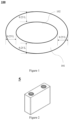
- Figure 1 is a schematic diagram of a cross-sectional image of the particles of carbon material 100 in the present application, and the cross-sectional image passes through the center of the particles of carbon material 100.
- L represents the short axis length of the particles of carbon material 100.
- the zone formed by extending a distance of 0.25 L from the surface of the particles of carbon material 100 inside the particles is the external zone 101, and the zone inside the external zone 101 is the internal zone 102.
- the area of the pore structure in the external zone of the carbon material is less than 0.15 ⁇ m 2 an optionally less than or equal to 0.10 ⁇ m 2 .
- the inventors have found that by controlling the area of the pore structure in the external zone of the carbon material to fall within the above range, the external zone of the carbon material can have a dense structure, which can effectively improve the structural stability of the carbon material, avoid electrolyte solution infiltration into the pore structure inside the carbon material particles as much as possible; accordingly, the cycling performance of the secondary battery is effectively improved.
- the present application is not intended to limit the areas of all pore structures in the external zone of the carbon material to be less than or equal to 0.15 ⁇ m 2 .
- the internal zone of the carbon material includes more than one pore structures having the area of equal to or greater than 0.15 ⁇ m 2 , and optionally more than one pore structures having the area of from 0.15 ⁇ m 2 to 2.0 ⁇ m 2 .
- the inventors have found that by including the pore structure of the above mentioned size in the internal zone of the carbon material, on the one hand, sufficient and stable expansion space can be reserved for the volume change of the carbon material particles, thereby reducing the risk of carbon material particle breakage; on the other hand, the compaction density of the carbon material and the energy density of secondary batteries are improved.
- the interlayer spacing of the external zone of the carbon material is denoted as d 1
- the interlayer spacing of the internal zone of the carbon material is denoted as d 2 .
- the carbon material satisfies d 1 ⁇ d 2 , and optionally, d 1 >d 2 .
- the interlayer spacing of the external zone of the carbon material under the condition that the interlayer spacing of the external zone of the carbon material is larger, it is more conducive to the rapid intercalation and deintercalation of active ions, thereby further improving the dynamic performances of the secondary battery. Under the condition that the interlayer spacing in the internal zone of carbon materials is smaller, it is more conducive to improving the capacity per gram and compaction density of the carbon material, thereby further enhancing the energy density of secondary batteries.
- d 1 is from 0.33565 nm to 0.33600 nm.
- d 2 is from 0.33553 nm to 0.33589 nm.
- the interlayer spacing of different zones of carbon materials can be tested using instruments and methods known in the art.
- HRTEM High-Resolution Transmission Electron Microscopy
- the test instrument may be Spectra S/TEM Scanning Transmission Electron Microscope from Thermo Fisher Scientific.
- the graphitization degree of the carbon material is from 93% to 98.5%, and optionally from 94% to 98%. Under the condition that the graphitization degree of carbon materials is within the above range, it is beneficial for the secondary batteries to have high energy density and simultaneously have good cycling performance and dynamic performances.
- the graphitization degree of carbon materials can be tested using instruments and methods well-known meaning in the art.
- the test can be conducted on an X-ray diffractometer (such as Bruker D8 Discover).
- the test can be conducted according to JIS K 0131-1996 and JB/T 4220-2011 to obtain the average interlayer spacing d 002 of (002) crystallographic planes in the crystal structure of carbon materials.
- the formula g (0.344 - d 002 )/(0.344 - 0.3354) ⁇ 100%
- the graphitization degree is calculated.
- d 002 is the average interlayer spacing of (002) crystallographic planes in the carbon material crystal structure expressed in nanometers (nm).
- the morphology of the carbon material includes one or more of blocky, spherical, and quasi-spherical shapes. This is beneficial for improving the compaction density of the negative electrode plate, and further for increasing the energy density of the secondary battery.
- the carbon material includes primary particles.
- primary particles account for ⁇ 50% by number of the carbon material, for example, from 55% to 95%, from 60% to 100%, from 65% to 90%, from 65% to 80%, from 70% to 100%, from 75% to 90%, from 80% to 100%, from 90% to 100%, or from 95% to 100%.
- the carbon material can have high structural stability, which reduces the side reactions and further increases the compaction density of the negative electrode plate. Accordingly, the energy density of the secondary battery is increased.
- the carbon material can be primary particles, that is, the primary particles accounts for 100% of the carbon material.
- Primary particles refer to non-agglomerated particles
- secondary particles refer to agglomerated particles formed by the aggregation of two or more than two primary particles.
- Primary and secondary particles can be distinguished by scanning electron microscopy (SEM) images.
- the proportion of primary particles in the carbon material can be tested as follows: any one test sample may be taken from the negative electrode film layer, the test is conducted on multiple areas of the test sample, the images of multiple test areas are obtained by scanning electron microscopy, and the proportion of the number of the carbon material particles having the primary particles morphology in each image to the total number of carbon material particles is counted, with the average of multiple counted results is the proportion of primary particles in the carbon material.
- the specific surface area of the carbon material is from 0.6 m 2 /g to 2.5 m 2 /g, and optionally from 0.8 m 2 /g to 2.4 m 2 /g.
- the carbon material of the present application has a lower specific surface area and lower surface activity, which can reduce the consumption of active ions in SEI film formation, improve the initial columbic efficiency of the carbon material, and improve the cycling performance of the secondary battery.
- the specific surface area of carbon materials having a well-known concept in the art, can be measured using well-known instruments and methods in the art. For example, according to GB/T 19587-2017, it may be tested by the nitrogen adsorption specific surface area analysis test method and be calculated by BET (Brunauer Emmett Teller) method.
- the nitrogen adsorption specific surface area analysis test method can be conducted on the Tri-Star 3020 specific surface area pore size analysis tester from Micromeritics, United States.
- the volume distribution particle size Dv50 of the carbon material is from 6 ⁇ m to 30 ⁇ m, and optionally from 8 ⁇ m to 25 ⁇ m.
- the transport performance of active ions and electrons is advantageously improved, thereby further improving the cycling and dynamic performances of secondary batteries.
- the particle size distribution (Dv90-Dv10)/Dv50 of the carbon material ranges from 0.90 to 1.50, and optionally from 0.90 to 1.45. Under the condition that the particle size distribution (Dv90-Dv10)/Dv50 of the carbon material is within the above ranges, the compaction density of the carbon material is advantageously improved, thereby further enhancing the energy density of secondary batteries.
- the volume distribution particle sizes Dv10, Dv50, and Dv90 of carbon materials have the well-known meanings in the art, and they represent the particle sizes corresponding to the cumulative volume distribution percentage of the material reaching 10%, 50%, and 90% respectively. They can be measured using instruments and methods known in the art. For example, according to GB/T 19077-2016 Particle size distribution analysis-Laser diffraction method, the test may be conventionally conducted on a laser particle size analyzer. The test instrument may be the Mastersizer 3000 laser particle size analyzer from Marvin Instruments Limited, UK.
- the tap density of the carbon material is from 0.8 g/cm 3 to 1.20 g/cm 3 , and optionally from 0.85g/cm 3 to 1.18g/cm 3 .
- the compaction density of the negative electrode plate can be increased, thereby increasing the energy density of the secondary battery.
- the active ion and electron transport performance, and enhance the cycling and/or dynamic performances of secondary batteries can be improved.
- the tap density of carbon materials can be measured using instruments and methods known in the art.
- the test may be conducted on a powder tap density tester.
- the test instrument may be BT- 301 tester from Dandong Baite.
- the powder compaction density of the carbon material under a pressure of 5000kg is from 1.85 g/cm 3 to 2.10 g/cm 3 , and optionally from 1.85 g/cm 3 to 2.08 g/cm 3 .
- the compaction density of the negative electrode plate can be increased, thereby increasing the energy density of the secondary battery.
- the active ion and electron transport performance, and enhance the cycling and/or dynamic performances of secondary batteries can be improved.
- the powder compaction density of carbon materials can be measured using instruments and methods known in the art.
- the test may be conducted on an electronic pressure testing machine (such as UTM7305 electronic pressure testing machine) according to GB/T 24533-2009.
- the exemplary test method is as follows: 1g of carbon material powder is weighted and added into a mold with a bottom area of 1.327cm 2 , a pressure of 5000kg is applied, holding for 30s, then the pressure is released, holding for 10s, and then the powder compaction density of the carbon material under 5000kg pressure is recorded and calculated.
- the capacity per gram of the carbon material is from 350 mAh/g to 370 mAh/g, and optionally from 355mAh/g to 370mAh/g. Under the condition that the capacity per gram of the carbon material is within the above range, the energy density of secondary batteries is improved.
- the capacity per gram of carbon materials has a well-known meaning in the art, and can be tested using methods well-known in the art.
- the exemplary test method is as follows: a carbon material sample is mixed under stirring with styrene butadiene rubber (SBR) as a binder, sodium carboxymethyl cellulose (CMC) as a thickener, and carbon black as a conductive agent in a mass ratio of 96.2:1.8:1.2:0.8 in an appropriate amount of deionized water as a solvent, to form a uniform negative electrode slurry; the negative electrode slurry is applied evenly on the surface of copper foil as the negative electrode current collector, and is reserved for later use after drying in an oven; ethylene carbonate (EC), methyl ethyl carbonate (EMC), and diethyl carbonate (DEC) are mixed in a volume ratio of 1:1:1 to obtain an organic solvent, and then LiPF 6 is dissolved in the aforementioned organic solvent to prepare an electrolyte solution with a concentration of 1mol/L
- the present application provides a method for preparing a carbon material, which may be used for preparing the carbon material according to the first aspect of the present application.
- the method for preparing a carbon material comprising the following steps:
- the raw material used for preparing the carbon material includes natural graphite.
- the natural graphite includes one or more of flake graphite, natural spherical graphite, and microcrystalline graphite, and more optionally including natural spherical graphite.
- natural spherical graphite refers to a natural graphite with spherical or quasi-spherical shape, but not all natural graphite particles are controlled to be ideal spheres.
- natural spherical graphite with the required particle size and morphology can be obtained by pre-treatment of flake graphite.
- the pre-treatment includes processes such as crushing, grading, spheroidization, and purification.
- the morphology of the raw material includes one or more of spherical and quasi-spherical shapes.
- the volume distribution particle size Dv50 of the raw material is from 6 ⁇ m to 30 ⁇ m, and optionally from 8 ⁇ m to 25 ⁇ m. Under the condition that the volume distribution particle size of the raw material are within the above ranges, it is beneficial for subsequent filling treatment.
- the OI value of the raw material is ⁇ 4, and optionally from 4 to 15. Under such circumstances, it is beneficial to for the final prepared carbon materials to have appropriate OI values, which can accelerate the transport of active ions and further improve the dynamic performances of secondary batteries.
- the OI value of the raw material having a well-known meaning in the art, can be tested using instruments and methods known in the art.
- the test may be conducted on an X-ray diffractometer (such as Bruker D8 Discover) according to JIS K 0131-1996 and JB/T 4220-2011 to obtain the X-ray diffraction pattern of the raw material powder.
- the volume distribution particle size Dv50 of the filling material is less than or equal to 6 ⁇ m, and optionally from 1 ⁇ m to 6 ⁇ m, from 2 ⁇ m to 5 ⁇ m, and from 3 ⁇ m to 5 ⁇ m. Under such circumstances, it is beneficial for the filling material to enter the pore structure of the raw material, and also further for improving the dispersion uniformity between the filling material and the raw material.
- the soften point temperature of the filling material is from 105°C to 190°C, and optionally from 105°C to 180°C, from 105°C to 175°C, from 105°C to 170°C, from 105°C to 165°C, from 105°C to 160°C, from 105°C to 155°C, from 105°C to 150°C, from 110°C to 180°C, from 110°C to 175°C, from 110°C to 170°C, from 110°C to 165°C, from 110°C to 155°C, from 110°C to 150°C, from 115°C to 180°C, from 115°C to 175°C, from 115°C to 170°C, from 115°C to 165°C, from 115°C to 160°C, from 115°C to 155°C, from 115°C to 150°C, and from 115°C to to
- the soften point temperature of the filling material within the above ranges is beneficial to adjusting I 3R(101) /I 2H(004) to fall within an appropriate range, and further beneficial to adjusting the size and/or number of pores in the external zone and internal zone of the carbon material to fall within an appropriate range.
- the coking value of the filling material is from 20% to 48%, and optionally from 25% to 40%.
- the inventors have found that under the condition that the coking value of the filling material is within the above ranges, it is beneficial to adjust I 3R(101) /I 2H(004) to fall within an appropriate range, and further is beneficial to adjust the pore size and/or pore numbers in the external zone and internal zone of the carbon material to fall within the appropriate range.
- the soften point temperature of the filling material is from 110°C to 165°C, and the coking value is from 25% to 40%.
- the coking value of the filling material is a well-known meaning in the art and can be measured using instruments and methods known in the art. For example, it can be determined according to GB/T 8727-2008.
- the filling material includes one or more of coal tar asphalt, petroleum asphalt, polymer compounds, and resins, and optionally includes petroleum asphalt.
- the mass ratio of the filling material to the raw material is (10 - 40): 100, and optionally (15 - 30): 100. This is beneficial to adjusting I 3R(101) /I 2H(004) to fall within the appropriate range, and to adjusting the size and/or number of pores in the external zone and internal zone of the carbon material to fall within the appropriate ranges.
- the heating process in which the raw material and the filling material after being uniformly mixed in a predetermined proportion are heated up to the first temperature T 1 , is a staged heating process, and optionally includes a first heating process and a second heating process.
- the first heating process involves heating to a temperature of from 200°C to 300°C and holding at that temperature for a time of from 1 to 3 hours.
- the inventors have found that under the condition that the holding time is within the above range, it is beneficial to adjust the pore size and/or pore numbers in the external zone and internal zone of carbon materials to fall within the appropriate range.
- the second heating process involves heating to the first temperature T 1 and holding for the first time t1 at that temperature.
- the first temperature T 1 ranges from 700°C to 1100 °C, and optionally from 750°C to 1100 °C, from 800°C to 1100°C, from 850°C to 1100 °C, from 900°C to 1100 °C, and from 950°C to 1100 °C.
- the inventors have found that under the condition that the first temperature is within the above range, the size and/or number of pores in the external zone and internal zone of carbon materials can be advantageously adjusted to be within an appropriate range. And the following situations can be effectively avoided: under the condition that the first temperature is too low, the filling material may not be fully converted into carbon material, and during the subsequent heat treating in step 3, it will continue to decompose into small molecule substances, resulting in the actual residual carbon in the filling area having a large pore structure, which fails to effectively modify the internal defects of the particles, and also cannot effectively prevent the electrolyte from infiltrating into the pore structure inside the obtained carbon material particles, This further affects the initial columbic efficiency and cycling performance of the secondary battery; Under the condition that the first temperature is too high, the energy consumption during the preparation process of carbon materials increases.
- the first time t 1 is from 1h to 5h.
- the first time t 1 can be 1 hour, 1.5 hours, 2 hours, 2.5 hours, 3 hours, 3.5 hours, 4 hours, 4.5 hours, 5 hours, or within a range formed by any two of the values above.
- the first time t 1 is from 2h to 4h.
- the inventors have found that under the condition that the first time is within the above range, the size and/or number of pores in the external zone and internal zone of the carbon material is advantageously adjusted to fall within an appropriate range. Accordingly, the following situations are effectively avoided: the first time is too short, so the filling material may not fully convert into a carbon material and thus will continue to decompose into small molecule substances during the subsequent heat treating in step 3, and therefore, the actual residual carbon in the filling area has many pore structures, which fails to effectively modify the internal defects of the particles, and cannot effectively prevent the electrolyte solution from infiltrating into the pore structure inside the obtained carbon material particles, so that the initial columbic efficiency and cycling performance of the secondary battery are affected; or the first time is too long, so the energy consumption during the preparation of the carbon material increases.
- the temperature is first raised to a temperature from 200°C to 300°C. Because the heating temperature is higher than the soften point temperature of the filling material, the filling material melts and softens under heating, and keeping the temperature for 1 to 3 hours allows the filling material to flow and fill into the pore structures of the raw material; then with the temperature raised to the first temperature, the filling material undergoes carbonization reaction, so that the pore structures occupied by the filling material can be filled effectively.
- the heating rate of the first heating process may be from 1°C/min to 10°C/min, and optionally from 1.5°C/min to 8°C/min.
- the inventors have found that under the condition that the heating rate is within the above ranges, it is beneficial to adjust the pore size and/or pore numbers in the external zone and internal zone of carbon materials to fall within the appropriate range.
- the heating rate of the second heating process can be from 2°C/min to 10°C/min, and optionally from 2.5°C/min to 8°C/min.
- the heat treating in step 2, can be carried out in a vertical granulation kettle, a horizontal granulation kettle, a vertical reaction kettle, a horizontal reaction kettle, or a drum furnace.
- the heat treating atmosphere may be a protective gas atmosphere.
- the protective gas may include one or more of nitrogen, argon, or helium.
- step 2 by adjusting one or more of the heating rate, first temperature, first time, heating process, etc. to fall within the above range, it is beneficial to adjust the pore size and/or number of pores in the external zone and internal zone of the carbon material to an appropriate range.
- the second temperature T 2 is from 1850°C to 2650°C, and optionally from 1950°C to 2580°C, from 1950°C to 2520°C, from 1950°C to 2480°C, from 1950°C to 2420°C, from 1950°C to 2360°C, from 2020°C to 2580°C, from 2020°C to 2520°C, from 2020°C to 2480°C, from 2020°C to 2420°C, from 2020°C to 2360°C, from 2100°C to 2580°C, from 2100°C to 2520°C, from 2100°C to 2480°C, from 2100°C to 2420°C, from 2100°C to 2420°C, and from 2100°C to 2360°C.
- the inventors have found that under the condition that the second temperature is within the above range, it is beneficial to adjust I 3R(101) /I 2H(004) to fall within the appropriate range, and to adjust the pore size and/or pore numbers in the external zone and internal zone of carbon materials to fall within the appropriate range.
- the following situations can be effectively avoided: under the condition that the second temperature is too low, the obtained carbon material has more surface defects and/or bulk defects and thus the I 3R(101) /I 2H(004) is larger, which leads to a decrease in the surface stability of the carbon material particles and an increase in particle surface side reactions, affecting the initial columbic efficiency and cycle performance of the secondary battery; under the condition that the second temperature is too high, the obtained carbon material cannot contain 3R phase crystalline carbon, and the interlayer spacing of the carbon material is small, which is not beneficial to the transport of active ions, affecting the dynamic performances of the secondary battery.
- the second time t 2 is from 1.5h to 6h.
- the second time t 1 may be 2h, 2.5h, 3h, 3.5h, 4h, 4.5h, 5h, 5.5h, 6h or within a range formed by any two of the above values.
- the second time t 2 is from 2h to 5h.
- the inventors have found that Under the condition that the second time is within the above range, it is beneficial to adjust I 3R(101) /I 2H(004) to fall within the appropriate range, and to adjust the pore size and/or number of pores in the external zone and internal zone of carbon materials to fall within the appropriate range.
- the following situations can be effectively avoided: under the condition that the second time is too short, the obtained carbon material has more surface defects and/or bulk defects and I 3R(101) /I 2H(004) is larger, which leads to a decrease in the surface stability of carbon material particles and an increase in side reactions on the particle surface, and further affects the initial columbic efficiency and cycle performance of the secondary battery; and under the condition that the second time is too long, the obtained carbon material may not contain 3R phase crystalline carbon and the interlayer spacing of the carbon material is small, which is not beneficial to the transport of active ions and affects the dynamic performances of the secondary battery.
- the heat treating in step 3, can be carried out in an intermediate frequency furnace, box type graphitization furnace, Acheson graphitization furnace, continuous graphitization furnace, or inner string graphitization furnace.
- the heat treating in the medium frequency furnace and continuous graphitization may be conducted under an atmosphere of protective gas atmosphere.
- the protective gas may include one or more of nitrogen, argon, or helium.
- the preparation method of the present application has low cost, high practicality, and is suitable for large to scale production.
- the present embodiment provides a secondary battery.
- the secondary battery may be a lithium-ion batteries.
- the secondary battery comprises a positive electrode plate, a negative electrode plate, and electrolytes.
- active ions repeatedly intercalate into and deintercalate out of between the positive electrode plate and the negative electrode plate, and the electrolyte plays a role in conducting active ions between the positive electrode plate and the negative electrode plate.
- electrolytes can be selected based on actual needs.
- the electrolytes can be at least one selected from of solid electrolyte and liquid electrolyte (i.e. electrolyte solution).
- the secondary batteries comprising electrolyte solution and the ones comprising solid electrolytes may further include a separator, which is arranged between the positive electrode plate and the negative electrode plate to separate them.
- the negative electrode plate includes a negative current collector and a negative film layer arranged on at least one surface of the negative current collector.
- the negative electrode current collector has two surfaces opposite in the thickness direction thereof, and the negative electrode film layer is arranged on either or both of the two opposite surfaces of the negative electrode current collector.
- the negative electrode film layer comprises the carbon material according to the first aspect of the present application or the carbon material prepared by the method described in the second aspect of the present application. Accordingly, the secondary battery can have high initial columbic efficiency and simultaneously have good cycling and dynamic performances.
- the negative electrode film layer may further include other negative electrode active materials in addition to the aforementioned carbon materials.
- the other negative electrode active materials include but are not limited to one or more of conventional natural graphite, artificial graphite, soft carbon, hard carbon, silicon-based materials, tin-based materials, and lithium titanate.
- the silicon-based material may include one or more of elemental silicon, silicon oxides, silicon carbon composites, silicon nitrogen composites, and silicon alloy materials.
- the tin-based material may include one or more of elemental tin, tin oxide, and tin alloy materials.
- the negative electrode film layer may optionally include a negative electrode conductive agent.
- the types of negative electrode conductive agents are not specially limited.
- the negative electrode conductive agent may include one or more of superconducting carbon, conductive graphite, acetylene black, carbon black, Koqin black, carbon dots, carbon nanotubes, graphene, and carbon nanofibers.
- the negative electrode film layer may optionally include a negative electrode binder.
- the type of negative electrode binders is not specially limited.
- the negative electrode binder may include one or more of styrene butadiene rubber (SBR), water-soluble unsaturated resin SR-1B, waterborne acrylic resin (such as polyacrylic acid PAA, polymethyl acrylic acid PMAA, and polyacrylic acid sodium PAAS), polyacrylamide (PAM), polyvinyl alcohol (PVA), sodium alginate (SA), and carboxymethyl chitosan (CMCS).
- the negative electrode film layer may optionally include other additives.
- other additives may include thickeners, such as sodium carboxymethyl cellulose (CMC), and PTC thermistor materials.
- the negative current collector may be a metal foil or composite current collector.
- the metal foil may be a copper foil.
- the composite current collector may include a polymer material as a base layer and a metal material layer formed on at least one surface of the base layer of polymer material.
- the metal material may include one or more of copper, copper alloys, nickel, nickel alloys, titanium, titanium alloys, silver, and silver alloys.
- the base layer of polymer material may include one or more of polypropylene (PP), polyethylene terephthalate (PET), polybutylene terephthalate (PBT), polystyrene (PS), and polyethylene (PE).
- the negative electrode film layer is usually formed by applying the negative electrode slurry on the negative electrode current collector, drying, and cold pressing.
- the negative electrode slurry is usually formed by dispersing the negative electrode active material, optional conductive agent, optional binder, and other optional additives in a solvent and stirring evenly.
- the solvent may be N-methylpyrrolidone (NMP) or deionized water, but is not limited thereto.
- the negative electrode plate does not exclude other additional functional layers other than the negative electrode film layer.
- the negative electrode plate described in the present application further includes a conductive primer layer sandwiched between the negative electrode current collector and the negative electrode film layer, arranged on the surface of the negative electrode current collector (for example, composed of a conductive agent and a binder).
- the negative electrode plate described in the present application also includes a protective layer covering on the surface of the negative electrode film layer.
- the positive electrode plate includes a positive current collector and a positive electrode film layer arranged on at least one surface of the positive current collector.
- the positive electrode current collector has two surfaces opposite in the thickness direction thereof, and the positive electrode film layer is arranged on either or both of the two opposite surfaces of the positive electrode current collector.
- the positive electrode current collector may be a metal foil or composite current collector.
- the metal foil may be an aluminum foil.
- the composite current collector may include a polymer material as a base layer and a metal material layer formed on at least one surface of the base layer of polymer material.
- the metal material may include one or more of aluminum, aluminum alloys, nickel, nickel alloys, titanium, titanium alloys, silver, and silver alloys.
- the base layer of polymer material may include one or more of polypropylene (PP), polyethylene terephthalate (PET), polybutylene terephthalate (PBT), polystyrene (PS), and polyethylene (PE).
- the positive electrode film layer typically includes a positive electrode active material, optional binders, and optional conductive agents.
- the positive electrode film layer is usually formed by applying the positive electrode slurry on the positive electrode current collector, drying, and cold pressing.
- the positive electrode slurry is usually formed by dispersing the positive electrode active material, optional conductive agent, optional binder, and any other components in a solvent and stirring evenly.
- the solvent may be N-methylpyrrolidone (NMP), but is not limited thereto.
- the binder used for the positive electrode film layer may include one or more of polyvinylidene fluoride (PVDF), polytetrafluoroethylene (PTFE), vinylidene fluoride-tetrafluoroethylene-propylene terpolymer, vinylidene fluoride-hexafluoropropylene-tetrafluoroethylene terpolymer, tetrafluoroethylene-hexafluoropropylene copolymer, and fluoroacrylate resin.
- PVDF polyvinylidene fluoride
- PTFE polytetrafluoroethylene
- PTFE polytetrafluoroethylene
- vinylidene fluoride-tetrafluoroethylene-propylene terpolymer vinylidene fluoride-hexafluoropropylene-tetrafluoroethylene terpolymer
- tetrafluoroethylene-hexafluoropropylene copolymer tetrafluor
- the conductive agents used for positive electrode film layers may include one or more of superconducting carbon, conductive graphite, acetylene black, carbon black, Koqin black, carbon dots, carbon nanotubes, graphene, and carbon nanofibers.
- the positive electrode active material may be a positive electrode active material commonly known in the art for secondary batteries.
- the positive electrode active material may include, but are not limited to, one or more of lithium-containing transition metal oxides, lithium-containing phosphates, and the modified compounds thereof.
- lithium transition metal oxides may include, but are not limited to, one or more of lithium cobalt oxide, lithium nickel oxide, lithium manganese oxide, lithium nickel cobalt oxide, lithium manganese cobalt oxide, lithium nickel manganese oxide, lithium nickel cobalt manganese oxide, lithium nickel cobalt aluminum oxide, and the modified compounds thereof.
- the examples of the lithium-containing phosphates may include, but are not limited to, one or more of lithium iron phosphate, the composite materials of lithium iron phosphate and carbon, lithium manganese phosphate, the composite materials of lithium manganese phosphate and carbon, lithium manganese iron phosphate, the composite materials of lithium manganese iron phosphate and carbon, and the modified compounds thereof.
- the positive electrode active material used for lithium to ion batteries can include one or more lithium transition metal oxides and their modified compounds with the general formula Li a Ni b Co c M d O e A f . 0.8 ⁇ a ⁇ 1.2, 0.5 ⁇ b ⁇ 1, 0 ⁇ c ⁇ 1, 0 ⁇ d ⁇ 1, 1 ⁇ e ⁇ 2, 0 ⁇ f ⁇ 1, M is one or more selected from Mn, Al, Zr, Zn, Cu, Cr, Mg, Fe, V, Ti, and B, and A selected is one or more from N, F, S, and Cl.
- positive electrode active materials for lithium-ion batteries may include one or more of LiCoO 2 , LiNiO 2 , LiMnO 2 , LiMn 2 O 4 , LiNi 1/3 Co 1/3 Mn 1/3 O 2 (NCM333), LiNi 0.5 CO 0.2 Mn 0.3 O 2 (NCM523), LiNi 0.6 Co 0.2 Mn 0.2 O 2 (NCM622), LiNi 0.8 Co 0.1 Mn 0.1 O 2 (NCM811), LiNi 0.85 Co 0.85 Al 0.05 O 2 , LiFePO 4 , and LiMnPO 4 .
- the electrolyte is an electrolyte solution, which includes an electrolyte salt and a solvent.
- electrolyte salts are not specifically restricted and can be selected according to actual needs.
- the electrolyte salt may include lithium hexafluorophosphate (LiPF 6 ), lithium tetrafluoroborate (LiBF 4 ), lithium perchlorate (LiClO 4 ), lithium hexafluoroarsenate (LiAsF 6 ), lithium difluorosulfonymide (LiFSI), lithium difluorosulfonymide (LiTFSI), lithium trifluoromethanesulfonate (LiTFS), lithium difluorooxalate borate (LiDFOB), lithium dioxalate borate (LiBOB)
- LiPF 6 lithium hexafluorophosphate
- LiBF 4 lithium tetrafluoroborate
- LiClO 4 lithium perchlorate
- LiAsF 6 lithium hexafluoroarsenate
- LiFSI lithium difluorosulfonymide
- LiTFSI lithium difluorosulfonymide
- LiTFS lithium trifluoromethan
- the material of the separator may include one or more of glass fibers, non to woven fabrics, polyethylene, polypropylene, and polyvinylidene fluoride.
- the separator can be a single layer thin film or a multi-layer composite thin film. Under the condition that the separator is a multi -layer composite film, the materials of each layer are the same or different.
- the positive electrode plate, the separator, and the negative electrode plate may be made into an electrode assembly through a winding or stacking process.
- the secondary battery may include an outer packaging.
- the outer packaging may be used to encapsulate the electrode components and electrolytes as mentioned above.
- the outer packaging can be a hard housing, such as a hard plastic housing, aluminum housing, steel housing, etc.
- the outer packaging can also be a soft bag, such as a bag-type soft bag.
- the material of the soft bag may be plastic, such as one or more of polypropylene (PP), polybutylene terephthalate (PBT), and polybutylene succinate (PBS).
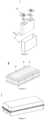
- the shapes of secondary batteries in the present application are not specially limited, and may be cylindrical, cubic, or any other shape. As shown in Figure 2 , a cubic structured secondary battery 5 is used as an example.
- the outer package may include a shell 51 and a cover plate 53.
- the shell 51 may include a bottom plate and side plates connected to the bottom plate, and the bottom plate and the side plates enclose an accommodating cavity.
- the shell 51 has an opening in communication with the accommodating cavity, and the cover plate 53 is closed to the opening to seal the accommodating cavity.
- the positive electrode plate, the negative electrode plate, and the separator may be wound or stacked to form an electrode assembly 52.
- the electrode assembly 52 is packaged in the accommodating cavity.
- the electrolytic solution infiltrates the electrode assembly 52.
- the secondary battery 5 includes one or more electrode assemblies 52, which may be adjusted according to requirements.
- the positive electrode plate, separator, negative electrode plate, and electrolytic solution may be assembled to form the secondary battery.
- the positive electrode plate, separator, and negative electrode plate may form an electrode assembly through a winding or stacking process, the electrode assembly is placed in an outer package and dried, then the electrolytic solution is injected, and the secondary battery is obtained after vacuum packaging, standing, formation, shaping, and other processes.
- the secondary battery of the present application may be assembled into a battery module.
- the battery module may include a plurality of secondary batteries, and the specific numbers may be adjusted according to the application and capacity of the battery module.
- FIG 4 is a schematic diagram of battery module 4 as an example.
- a plurality of secondary batteries 5 may be arranged in sequence along a length of the battery module 4.
- the secondary batteries may alternatively be arranged in any other manner.
- the plurality of secondary batteries 5 may be fixed by fasteners.
- the battery module 4 may further include a housing having an accommodating space, and the plurality of secondary batteries 5 are accommodated in the accommodating space.
- the foregoing battery module may alternatively be assembled into a battery pack, and the number of the battery module included in the battery pack may be adjusted according to the application and capacity of the battery pack.
- FIGS 5 and 6 are schematic diagrams of a battery pack 1 as an example.
- the battery pack 1 may include a battery box and a plurality of battery modules 4 disposed in the battery box.
- the battery box includes an upper box body 2 and a lower box body 3.
- the upper box body 2 covers the lower box body 3 to form a closed space for accommodating the battery modules 4.
- the plurality of battery modules 4 may be arranged in the battery box in any manner.
- the present application provides an electrical device, comprising at least one of the secondary battery, the battery module, and the battery pack of the present application.
- the secondary battery, battery module, and battery pack may be used as a power source of the electrical device or as an energy storage unit of the electrical device.
- the electrical device may be, but is not limited to, a mobile device (such as a mobile phone, a tablet, or a laptop), an electric vehicle (such as a full electric vehicle, a hybrid electric vehicle, a plug-in hybrid electric vehicle, an electric bicycle, an electric scooter, an electric golf cart, or an electric truck), an electric train, a ship, a satellite, an energy storage system, or the like.
- the electrical device may be selected as the secondary battery, battery modules, or battery packs according to its usage requirements.
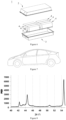
- FIG. 7 is a schematic diagram of an electrical device as an example.
- the electrical device is a full electric vehicle, a hybrid electric vehicle, a plug-in hybrid electric vehicle, or the like.
- the battery pack or the battery module may be used.
- the electrical device may be a mobile phone, a tablet, a laptop, etc.
- the electrical device is generally required to be thin and light, so the secondary battery may be used as a power source.
- Step 1 100 mesh flake graphite was mechanical crushed, graded, spheroidized, and purified, to obtain natural spherical graphite having a volume distribution particle size Dv50 of 12 ⁇ m and the OI value of 5.5.
- Step 2 The obtained natural spherical graphite and petroleum asphalt (having a soften point temperature of 142°C, a volume distribution particle size Dv50 of 5 ⁇ m, and a coking value of 35%) were mixed at a mass ratio of 100:20 in a VC mixer for 30 minutes, and then the mixed materials were placed in a drum furnace, where the temperature was raised at a rate of 4°C/min to 220°C and was kept for 2 hours (the first heating process), and then the temperature was raised at a rate of 5°C/min to 1100°C and was kept for 1.5 hours (the second heating process). Then, the temperature was cooled to room temperature to obtain the intermediate.
- Step 3 The obtained intermediate was placed in the Acheson graphitization furnace, and the temperature was raised to 2320°C and kept for 3 hours. After demagnetizing and screening, the carbon material was obtained.
- the above prepared carbon material was mixed with the styrene butadiene rubber (SBR) as a binder, sodium carboxymethyl cellulose (CMC) as a thickener, and conductive carbon black in an appropriate amount of solvent deionized water in a mass ratio of 96.2:1.8:1.2:0.8, to form a uniform negative electrode slurry; the negative electrode slurry was applied evenly on the surface of the negative electrode current collector copper foil, and was dried in an oven for later use.
- Ethylene carbonate (EC), methyl ethyl carbonate (EMC), and diethyl carbonate (DEC) were mixed in a volume ratio of 1:1:1 to obtain an organic solvent.
- LiPF 6 was dissolved in the aforementioned organic solvent to prepare an electrolytic solution with a concentration of 1 mol/L.
- a CR2430 button battery was assembled in an argon protected glove box by using a metal lithium plate as the counter electrode and polyethylene (PE) film as the separator.
- the above prepared carbon material, conductive agent carbon black (Super P), styrene butadiene rubber as a binder, and sodium carboxymethyl cellulose as a thickener were mixed in an appropriate amount of solvent deionized water in a weight ratio of 96:1:1:2 to form a negative electrode slurry.
- the negative electrode slurry was applied onto the two surfaces of the negative electrode current collector copper foil, and after drying and cold pressing, the negative electrode plate was obtained.
- LiFePO 4 , conductive carbon black and polyvinylidene fluoride were mixed in a weight ratio of 96:2.5:1.5, then an appropriate amount of solvent NMP was added under homogeneous stirring, to obtain the positive electrode slurry.
- the positive electrode slurry was applied onto the two surfaces of the positive electrode current collector aluminum foil, and after drying and cold pressing, the positive electrode plate was obtained.
- the polypropylene film having a thickness of 12 ⁇ m was used as a separator, and was placed with the positive and negative electrode plates prepared above in sequence, so that the separator was between the positive and negative electrode plates for separation; then they were wound to obtain the electrode assembly; the electrode assembly was placed in the outer packaging and dried, after which the electrolyte solution identical to that for the preparation of the button battery was injected. After vacuum encapsulation, standing, formation, capacity, and other processes, the secondary battery was obtained.
- the preparation methods for half cells and full cells are similar to Example 1, except that the preparation process of carbon materials is different.
- the preparation methods for half cells and full cells are similar to Example 1, except that the preparation process of carbon materials is different.
- the obtained natural spherical graphite and petroleum asphalt (having a soften point temperature of 142°C, a volume distribution particle size Dv50 of 5 ⁇ m, and a coking value of 35%) were mixed at a mass ratio of 100:20 in a VC mixer for 30 minutes, and then the mixed materials were graphitized at 3200°C for 6 hours. After cooled to room temperature, the carbon material was obtained.
- the preparation methods for half cells and full cells are similar to Example 1, except that the preparation process of carbon materials is different.
- the obtained natural spherical graphite and petroleum asphalt (having a soften point temperature of 142°C, a volume distribution particle size Dv50 of 5 ⁇ m, and a coking value of 35%) were mixed at a mass ratio of 100:20 in a VC mixer for 30 minutes, and then the mixed materials were graphitized at 1300°C for 3 hours. After cooling to room temperature, the carbon material was obtained.
- the preparation methods for half cells and full cells are similar to Example 1, except that the preparation process of carbon materials is different.
- the obtained natural spherical graphite and petroleum asphalt (having a soften point temperature of 142°C, a volume distribution particle size Dv50 of 5 ⁇ m, and a coking value of 35%) were mixed in a VC mixer for 30 minutes. Afterwards, the mixed materials were put into the reaction kettle, which were heated stepwise at a heating rate of 2°C/min under evenly stirring.
- the reaction kettle was vacuumed to a pressure of to -0.1MPa, and held for 2 hours; afterwards, the reaction kettle was heated up to 650°C and held for 2 hours, then cooled to a temperature of to about 160°C, after which petroleum asphalt was slowly added in the reaction kettle in an amount that was 1: 1 in mass relative to the amount of the petroleum asphalt added previously. Then, the reaction kettle was heated to 190°C again, vacuumed to the pressure of -0.1MPa, and held for 2 hours; afterwards, it was heated to 650°C and held for 2 hours, and then cooled via condensation. Last, the materials treated by the above process were heat-treated at 1300°C for 3 hours, and then were crushed and sieved to obtain a carbon material without internal pores.
- the X-ray diffraction patterns of carbon materials were obtained by conducting test on an X-ray diffractometer according to JIS K 0131-1996.
- the test conditions are as follows: the carbon materials were sampled using the flat plate sampling method and were tests under conditions of using CuK ⁇ -Ray as radiation source, copper target as the anode target, voltage 40KV, current 40mA, anti-scattering slit 1mm, scanning 20 angle range as from 20° to 80°, a step size of 0.01671°, a duration of 0.24 seconds per step, and a scanning rate of 4 °/min.
- the test instrument was a Bruker D8 Discover X-ray diffractometer.
- 20 of the diffraction peak of 3R phase 101 crystallographic plane was from 43° to 44°
- 20 of the diffraction peak of 2H phase 004 crystallographic plane was from 53° to 55°
- 2 ⁇ of the diffraction peak of 3R phase (012) crystallographic plane was from 46° to 47°.
- the diffraction peak intensity of 101 crystallographic plane of 3R phase and that of 004 crystallographic plane of 2H phase are represented by the corresponding integral area of the diffraction peaks.
- the binder for sample preparation was evenly mixed with carbon material powder and then the mixture was applied on the copper foil, drying at 60°C for 30 minutes for later use; the samples were cut into pieces of 6mm ⁇ 6mm and then were pasted on the sample stage of CP Type Argon Ion Cross-Section Polisher; the samples were cut using a plasma beam to obtain the cross-section of the carbon material, the cross-section of the carbon material passed through the center of the carbon material particles.
- the test instrument may be the IB- 09010 CP Argon Ion Cross-Section Polisher from JEOL, Japan.
- the cross-section of the carbon materials were scanned using a scanning electron microscope.
- the test may be conducted according to JY/T010-1996.
- the test instrument may be Sigma 300 Scanning Electron Microscope from ZEISS, Germany.
- the zone formed by extending a distance of 0.25 L from the surface of carbon material particles inside the particles is denoted as the external zone, and the zone inside the external zone is denoted as the internal zone.
- L represents the short axis length of carbon material particles.
- the button battery as prepared above was firstly discharged to current of 0.005V at a constant current of 0.15mA at 25°C, standing for 5 minutes, and then was discharged to 0.005V at a constant current of 10 ⁇ A, the initial cycling discharge capacity of the button battery was recorded; afterwards, it was charged to 2.0V at a constant current of 0.3mA and the initial cycling charging capacity of the button battery was recorded.
- the initial columbic efficiency of carbon materials (%) initial cycling charge capacity of button battery/initial cycling discharge capacity of button battery ⁇ 100%.
- the secondary battery as prepared above was charged at a constant current of 1C to the upper limit cutoff voltage (corresponding to 100% SOC), then charged at the constant voltage to a current of 0.05C, standing for 5 minutes, and was discharged at a constant current of 1C to the lower limit cutoff voltage (corresponding to 0% SOC).
- the discharge capacity of the present time was recorded as the initial cycling discharge capacity.
- the secondary battery was discharged at a constant current of 1C to the lower limit cut-off voltage (corresponding to 0% SOC). Afterwards it was charged at a constant current of 1C to the upper limit cut-off voltage (corresponding to 100% SOC), then was charged at the constant voltage until the current is 0.05C, at which moment the secondary battery was fully charged. After standing for 5 minutes, the fully charged secondary battery was discharged at a constant current of 1C to the lower cut-off voltage (corresponding to 0% SOC), and the discharge capacity of the present time was the actual capacity of the secondary battery at a rate of 1C, denoted as C0.
- the secondary battery was charged to the upper limit cut-off voltage (corresponding to 100% SOC) at a rate of xC0 (representing gradient charging rate, such as 1 C0, 1.05 C0, 1.1 C0, 1.15 C0, 1.2 C0, 1.25 C0, 1.3 C0, 1.35 C0, 1.4 C0 ...), and then was charged at the constant voltage until the current is 0.05 C0. After standing for 5 minutes, the secondary battery was disassembled to observe the lithium precipitation on the surface of the negative electrode plate. If there was no lithium precipitation on the surface of the negative electrode plate, increase the charging rate and test again until lithium deposition appears on the surface of the negative electrode plate. Record the maximum charging rate at which no lithium was precipitated on the surface of the negative electrode plate. Table 2 Nos.
- the specific surface area, volume distribution particle size, particle size distribution, graphitization degree, tap density, powder compaction density and other parameters of the carbon material prepared in Examples 1 to 17 are all within the range recorded in the specification of the present application.
- Figure 8 shows the X-ray diffraction pattern of the carbon material prepared in Example 1.
- the battery could balance high initial columbic efficiency with good cycling and dynamic performances; and under the condition that the X-ray diffraction pattern of the carbon materials further satisfies 0.005 ⁇ I 3R(101) /I 2H(004) ⁇ 0.100, and optionally satisfies 0.008 ⁇ I 3R(101) /I 2H(004) ⁇ 0.065, the battery could better balance high initial columbic efficiency and good cycling and dynamic performances.
- the carbon material particles further exhibited the following characteristics: the number and/or size of the pores in the internal zone were large, whereas the number and/or size of the pores in the external zone were small.
- the pore structure in the internal zone of carbon materials could reserve the expansion space necessary for the volume change of carbon material particles, thereby reducing the risk of carbon material particle breakage and generating new interfaces, and further reducing the side reactions and the irreversible capacity loss of batteries.
- the carbon material particles Under the condition that the number and/or size of the pores in the external zone were small, the carbon material particles had a more stable structure and the electrolyte infiltration into the pore structure inside the carbon material particles could be avoided as much as possible, thereby reducing the side reactions and the consumption of active ions by SEI film formation inside the particles. Therefore, the carbon materials that further satisfy the above structural characteristics could further enhance the comprehensive performance of the battery.
- Comparative Example 1 the untreated natural spherical graphite was used as the carbon material, and the carbon material particles had many pores and defects therein.
- Table 2 it can be concluded that the batteries as prepared had poor initial columbic efficiency, cycle performance, and dynamic performances.
- the carbon material prepared in Comparative Example 2 was natural spherical graphite having a carbon coating layer on the surface thereof. Due to the high heat treating temperature and long heat treating time, the interlayer spacing of the carbon material is small, which is not beneficial to the transport of active ions. As known from the test results as shown in Table 2, the battery as prepared had poor the dynamic performances; in addition, the coating layer existed only on the surface of natural spherical graphite but failed to achieve effective filling, and thus could not effectively prevent the infiltration of the electrolyte solution into the pore structure inside the particles, resulting in the limited improvement of battery cycling performance.
- the carbon material prepared in Comparative Example 3 was natural spherical graphite having a carbon coating layer on the surface thereof. Due to the low heat treating temperature, the main component of the coating layer is amorphous carbon, and there are many surface defects and/or bulk defects in the carbon material; in addition, the coating layer existed only on the surface of natural spherical graphite but failed to achieve effective filling, thus the infiltration of the electrolyte solution into the pore structure inside the particles could not be effectively prevented, resulting in limited improvement of battery cycling performance and dynamic performances.
- Comparative Example 4 when preparing the carbon materials, the filling materials were filled into the entire pore structures of natural spherical graphite particles by vacuum pumping. Due to the low heat treating temperature, there is a large amount of amorphous carbon inside and on the surface of the carbon material particles; moreover, there were no pore structures inside the carbon material particles as obtained. Accordingly, the carbon material, during the deintercalation and intercalation of active ions, had significant volume change, making the particles more likely to break. As a result, the improvement in the cycling and dynamic performances of the battery was limited.
Landscapes
- Chemical & Material Sciences (AREA)
- Inorganic Chemistry (AREA)
- Organic Chemistry (AREA)
- Chemical Kinetics & Catalysis (AREA)
- Electrochemistry (AREA)
- General Chemical & Material Sciences (AREA)
- Materials Engineering (AREA)
- Life Sciences & Earth Sciences (AREA)
- General Life Sciences & Earth Sciences (AREA)
- Geology (AREA)
- Engineering & Computer Science (AREA)
- Battery Electrode And Active Subsutance (AREA)
- Carbon And Carbon Compounds (AREA)
Abstract
Description
- The present application belongs to the field of battery technology, and specifically relates to a carbon material and the method for preparing the same, and a secondary battery and an electrical device comprising the same.
- In recent years, secondary batteries have been widely used in energy storage power systems such as hydropower, firepower, wind power, and solar power plants, as well as in various fields such as electric tools, electric bicycles, electric motorcycles, electric vehicles, military equipment, and aerospace. With the increasing applications of secondary batteries, people have posed serious challenges to the performance of secondary batteries, for example the requirement for a combination of energy density, dynamic performances, and service life of the secondary batteries. Negative electrode active materials are an important part of secondary batteries, because they affect the performances of the secondary batteries. At present, the negative electrodes active materials mainly includes graphite. However, the problem in the prior art is that the graphite having high capacity is difficult to have high initial columbic efficiency simultaneously, and thus is difficult to make the secondary batteries have good cycling and dynamic performances.
- The present application is intended to provide a carbon material, a method for preparing the same, and a secondary battery and an electrical device comprising the same. The carbon material provided in the present application can make the secondary battery have high initial columbic efficiency and also good cycling and dynamic performances.
- A first aspect of the present application provides a carbon material comprising a pore structure, wherein the carbon material has 3R and 2H phases and satisfies 0 < I3R(101)/I2H(004) ≤ 0.100, in which I3R(101) is the diffraction peak intensity of 101 crystallographic plane of the 3R phase in the X-ray diffraction pattern of the carbon material, and I2H(004) is the diffraction peak intensity of 004 crystallographic plane of the 2H phase in the X-ray diffraction pattern of the carbon material..
- During the research, the inventors have found that under the condition that both 3R phase crystalline carbon and 2H phase crystalline carbon exist in the carbon material, and the ratio of the diffraction peak intensity of 101 crystallographic plane of 3R phase to the diffraction peak intensity of 004 crystallographic plane of 2H phase satisfies 0 < I3R(101)/I2H(004) ≤ 0.100, there can be more active sites on the surface of carbon material particles, which can accelerate the transport of active ions. At the same time, the surface stability of carbon material particles is relatively high, which can effectively reduce surface side reactions and reduce the consumption of active ions. The carbon material provided in the present application includes a pore structure, which can reserve the expansion space necessary for the volume change of carbon material particles, thereby reducing the risk of carbon material particle breakage and generating new interfaces, and further reducing the side reactions and reducing the consumption of active ions. Therefore, the carbon material provided in the present application can balance high ion transport performance, high surface stability, and low volume change, thereby enabling the secondary battery comprising the same to combine high initial columbic efficiency and good cycling and dynamic performances.
- In some embodiments of the present application, 0.005 ≤ I3R(101)/I2H(004) ≤ 0.100, and optionally, 0.008 ≤I3R(1O1)/I2H(004) ≤ 0.065. Under the condition that the carbon material has I3R(101)/I2H(004) further falling within the above range, it can better balance the high initial columbic efficiency and good cycling and dynamic performances of the secondary battery.
- In some embodiments of the present application, the X-ray diffraction pattern of the carbon material does not include a peak position of (012) crystallographic plane of the 3R phase. Accordingly, the carbon material particles have fewer internal defects, which can further reduce the consumption of active ions and improve the initial columbic efficiency and cycling performance of secondary batteries.
- In some embodiments of the present application, the carbon material comprises more than one pore structure having a pore area of equal to or greater than 0.15 µm2, and optionally more than one pore structure having a pore area of from 0.15 µm2 to 2.0 µm2. In further research, the inventors found that under the condition that the carbon material includes a pore structure having the aforementioned pore area, the pore structure can reserve the expansion space necessary for the volume change of carbon material particles, thereby reducing the risk of carbon material particle breakage and generating new interfaces, and further reducing the side reactions and irreversible capacity loss of secondary batteries; as a result, the cycling performance of secondary batteries is improved.
- In some embodiments of the present application, the carbon material comprises an external zone and an internal zone located inside the external zone, the external zone refers to the zone formed by extending a distance of 0.25 L from the surface of the carbon material particles to the inside of the carbon material particles, L refers to the short axis length of the carbon material particles, the external zone has a total pore area denoted as S1, and the internal zone has a total pore area denoted as S2, wherein S2 > S1. Under the condition that the carbon material further satisfies S2 > S1, the carbon material can effectively reduce the irreversible capacity loss of the secondary battery, improve the capacity exertion characteristics of the secondary battery, and better balance the high initial columbic efficiency, as well as good cycling and dynamic performances of the secondary battery.
- In some embodiments of the present application, 1.5 ≤ S2/S1 ≤ 420, and optionally, 2 ≤ S2/S1 ≤ 300. Under the condition that S2/S1 further satisfies the above condition, the secondary battery can better balance the high initial columbic efficiency, and good cycle performance and dynamic performances.
- In some embodiments of the present application, 0.01µm2 ≤ S1 ≤ 5.0µm2, and optionally, 0.02µm2 ≤ S1 ≤ 4.5µm2. On the one hand, the carbon material particles can have a more stable structure, avoiding electrolyte to infiltrate into the pore structure inside the carbon material particles as much as possible, thereby reducing the side reactions and reducing the consumption of active ions by SEI membrane formation inside the carbon material particles. On the other hand, the transport performance of active ions and electrons will not be affected.
- In some embodiments of the present application, 2.5µm2 ≤ S2 ≤ 25.0µm2, and optionally, 3.0µm2 ≤ S2 ≤ 22.5µm2. On the one hand, sufficient and stable expansion space can be reserved for the volume change of the carbon material particles, thereby reducing the risk of the carbon material particle breakage and generating new interfaces, reducing the side reactions on the new interface surface, and reducing the consumption of active ions by SEI film formation on the new interface surface. On the other hand, the capacity and initial columbic efficiency of carbon materials can be improved.
- In some embodiments of the present application, L ≥ 4 µm, and optionally, 4 µm ≤ L ≤ 20 µm.
- In some embodiments of the present application, the pore structure in the external zone of the carbon material has an area of less than 0.15 µm2, and optionally less than or equal to 0.10 µm2. By controlling the area of the pore structure in the external zone of the carbon material within the above range, the external zone of the carbon material can have a dense structure, which can effectively improve the structural stability of the carbon material, avoid electrolyte infiltration into the pore structure inside the carbon material particles as much as possible, and thus effectively improve the cycling performance of the secondary battery.
- In some embodiments of the present application, the internal zone of the carbon material includes more than one pore structure having an area of greater than or equal to 0.15 µm2, and optionally includes more than one pore structure having an area of from 0.15 µm2 to 2.0 µm2. By including the pore structure of the above mentioned size in the internal zone of the carbon material, sufficient and stable expansion space can be reserved for the volume change of the carbon material particles, thereby reducing the risk of the carbon material particle breakage. On the other hand, the compaction density of carbon materials and increase the energy density of the secondary battery can be improved.
- In some embodiments of the present application, the specific surface area of the carbon material is from 0.6 m2/g to 2.5 m2/g, and optionally from 0.8 m2/g to 2.4 m2/g. The carbon material of the present application has a relatively low specific surface area and relatively low surface activity, which can reduce the consumption of active ions in SEI film formation, improve the initial columbic efficiency of the carbon material, and improve the cycling performance of the secondary battery.
- In some embodiments of the present application, the volume distribution particle size Dv50 of the carbon material is from 6 µm to 30 µm, and optionally from 8 µm to 25 µm.
- Under the condition that the volume distribution particle size and particle size Dv50 of carbon materials are within the above range, it is beneficial to improve the transport performance of active ions and electrons, thereby further improving the cycling and dynamic performances of secondary batteries.
- In some embodiments of the present application, the particle size distribution (Dv90-Dv10)/Dv50 of the carbon material is from 0.90 to 1.50, and optionally from 0.90 to 1.45. Under this circumstances, it is beneficial for improving the compaction density of carbon materials, and in turn enhance the energy density of secondary batteries.
- In some embodiments of the present application, the graphitization degree of the carbon material is from 93% to 98.5%, and optionally from 94% to 98%. Under the condition that the graphitization degree of carbon materials is within the above range, it is beneficial for secondary batteries to balance high energy density, good cycling performance, and dynamic performances.
- In some embodiments of the present application, the morphology of the carbon material includes one or more of blocky, spherical, and quasi-spherical shapes.
- In some embodiments of the present application, the tap density of the carbon material is from 0.8g/cm3 to 1.20g/cm3, and optionally from 0.85g/cm3 to 1.18g/cm3. Under the condition that the tap density of the carbon material is within the above range, the compaction density of the negative electrode plate can be increased, thereby increasing the energy density of the secondary battery. Moreover, the active ion and electron transport performance, and enhance the cycling and/or dynamic performances of secondary batteries can be improved.
- In some embodiments of the present application, the powder compaction density of the carbon material under a pressure of 5000kg is from 1.85g/cm3 to 2.10g/cm3, and optionally from 1.85g/cm3 to 2.08g/cm3. Under the condition that the powder compaction density of the carbon material is within the above range, the compaction density of the negative electrode plate can be improved, thereby increasing the energy density of the secondary battery. Moreover, the active ion and electron transport performance, and enhance the cycling and/or dynamic performances of secondary batteries can be improved.
- In some embodiments of the present application, the capacity per gram of the carbon material is from 350mAh/g to 370mAh/g, and optionally from 355mAh/g to 370mAh/g. Under the condition that the capacity per gram of carbon materials is within the above range, the energy density of secondary batteries can be improved.
- A second aspect of the present application provides a method for preparing a carbon material, comprising the following steps:
-
Step 1, providing a raw material having multiple pore structures; -
Step 2, mixing the raw material with a filling material in a predetermined proportion homogeneously, and then holding at a first temperature T1 for the first time t1 to obtain an intermediate; - Step 3, holding the obtained intermediate at a second temperature T2 for a second time t2 to obtain a carbon material,
- wherein the carbon material comprises a pore structure, and the carbon material has 3R and 2H phases and satisfies 0 < I3R(101)/I2H(004) ≤ 0.100, in which I3R(101) is the diffraction peak intensity of 101 crystallographic plane of the 3R phase in the X-ray diffraction pattern of the carbon material, and I2H(004) is the diffraction peak intensity of 004 crystallographic plane of the 2H phase in the X-ray diffraction pattern of the carbon material.
- In some embodiments of the present application, the raw material includes natural graphite, and optionally the natural graphite includes one or more of flake graphite, natural spherical graphite, and microcrystalline graphite.
- In some embodiments of the present application, the volume distribution particle size Dv50 of the raw material is from 6 µm to 30 µm, and optionally from 8 µm to 25 µm.
- In some embodiments of the present application, the OI value of the raw material is ≥ 4, and optionally from 4 to 15.
- In some embodiments of the present application, the volume distribution particle size Dv50 of the filling material is less than or equal to 6 µm, and optionally from 1 µm to 5 µm.
- In some embodiments of the present application, the soften point temperature of the filling material is from 105°C to 190°C, and optionally from 110°C to 165°C.
- In some embodiments of the present application, the coking value of the filling material is from 20% to 48%, and optionally from 25% to 40%.
- In some embodiments of the present application, the filling material includes one or more of coal tar asphalt, petroleum asphalt, polymer compounds, and resins, and optionally includes petroleum asphalt.
- In some embodiments of the present application, the mass ratio of the filling material to the raw material is (10 to 40) : 100, and optionally is (15 to 30) : 100.
- By adjusting one or more parameters of the filling material such as the type, softening point, coking value, and addition amount thereof to fall within the above ranges, I3R(101)/I2H(004) is advantageously adjusted to fall within the appropriate range, and the size and/or number of pores in the external zone and internal zone of the carbon material is/are advantageously adjusted to fall within the appropriate ranges. In addition, the filling material, after heating and melting, has a viscosity not too high, maintains good fluidity, and is not likely to bond the raw material particles. Accordingly, the aggregation of raw material particles in the subsequent preparation process can be reduced, thereby reducing the problem of increasing surface defects and side reactions of the carbon material particles due to the need for additional depolymerization processes.
- In some embodiments of the present application, after mixing the raw material and filling material in a predetermined proportion homogeneously, they are heated to the first temperature T1 by a staged heating process, optionally including a first heating process and a second heating process.
- In some embodiments of the present application, the first heating process is heating to a temperature of from 200°C to 300°C and holding at this temperature for 1 to 3 hours.
- In some embodiments of the present application, the second heating process is heating to the first temperature T1 and holding at the first temperature T1 for the first time t1.
- In some embodiments of the present application, the first temperature T1 is from 700°C to 1100°C, and optionally from 850 to 1100°C.
- In some embodiments of the present application, the first time t1 is from 1 hour to 5 hours, and optionally from 2 hours to 4 hours.
- By adjusting one or more of the factors such as heating rate, first temperature, first time, and heating process to fall within the above ranges, it is beneficial to adjust the pore size and/or number of pores in the external zone and internal zone of carbon materials to fall within the appropriate range.
- In some embodiments of the present application, the second temperature T2 is from 1850°C to 2650°C, and optionally from 2100°C to 2480°C.
- In some embodiments of the present application, the second time t2 is from 1.5h to 6h, and optionally from 2h to 5h.
- By adjusting the second temperature and/or time to fall within the above range, it is beneficial to adjust I3R(101)/I2H(004) to fall within the appropriate range, and is beneficial to improve the cycling and/or dynamic performances of the secondary battery.
- A third aspect of the present application provides a secondary battery, comprising a negative electrode plate comprising the carbon material according to the first aspect of the present application or the carbon material prepared by the method according to the second aspect of the present application.
- A fourth aspect of the present application provides an electrical device, comprising the secondary battery according to the third aspect of the present application.
- The carbon material prepared in the present application has fewer surface defects and/or bulk defects. The carbon material can balance high ion transport performance, high surface stability, and low volume change, thereby enabling the secondary battery comprising the same to balance high initial columbic efficiency, and good cycling and dynamic performances. The electrical device of the present application includes the secondary battery provided in the present application, and thus has at least the same advantages as the secondary battery.
- In order to provide a clearer explanation of the technical solution of the embodiments of the present application, a brief introduction will be given to the accompanying drawings required in the embodiments of the present application. It is evident that the accompanying drawings described below are only some embodiments of the present application. For those skilled in the art in the art, other accompanying drawings can be obtained based on the drawings without any creative effort.
-
Figure 1 is a schematic diagram of one cross-section image of the carbon material particles of the present application. -
Figure 2 is a schematic diagram of the secondary battery of one embodiment of the present application. -
Figure 3 is an exploded schematic diagram of the secondary battery of one embodiment of the present application. -
Figure 4 is a schematic diagram of the battery module of one embodiment of the present application. -
Figure 5 is a schematic diagram of the battery pack of one embodiment of the present application. -
Figure 6 is an exploded schematic diagram of the battery pack as shown inFigure 5 . -
Figure 7 is a schematic diagram of an electrical device of an embodiment, comprising a secondary battery as a power source according to the present application. -
Figure 8 is the X-ray diffraction pattern of the carbon material prepared in Example 1. - The accompanied drawings may not necessarily be drawn to the actual scale. The references in the figures are as follows: 1 battery pack, 2 upper box, 3 lower box, 4 battery module, 5 secondary battery, 51 shell, 52 electrode assembly, 53 cover, 100 carbon material, 101 external zone, 102 internal zone.
- Hereinbelow, the embodiments of the carbon materials of the present application, the method for preparing the same, and the secondary battery and electrical device comprising the same will be described in detail with appropriate reference to the accompanied drawings. However, there may be situations where unnecessary detailed explanations may be omitted. For example, there are situations where detailed explanations of well-known matters are omitted and repeated explanations of the same structure are actually provided. This is to avoid the following explanations becoming unnecessarily lengthy and easy for those skilled in the art to understand. In addition, the accompanying drawings and the following explanations are provided for those skilled in the art to fully understand the present application and are not intended to limit the subject matter recorded in the claims.
- The "scope" disclosed in the present application is limited in the form of a lower limit and an upper limit. The given scope is limited by selecting a lower limit and an upper limit, and the selected lower limit and upper limit the boundary of the special scope. The range limited in this way can include or exclude end values, and can be arbitrarily combined, that is, any lower limit can be combined with any upper limit to form a range. For example, if a range of 60-120 and 80-110 is listed for specific parameters, it is also expected to be understood as a range of 60-110 and 80-120. In addition, if the
minimum range values maximum range values integers - Unless otherwise specified, all embodiments and optional embodiments of the present application can be combined to form new technical solutions, which should be deemed to be included in the disclosure of this application.
- Unless otherwise specified, all technical features and optional technical features of the present application can be combined to form new technical solutions, which should be deemed to be included in the disclosure of this application.
- Unless otherwise specified, all steps of the present application can be carried out in sequence or randomly, preferably in sequence. For example, the method includes steps (a) and (b), indicating that the method can include steps (a) and (b) that are sequentially performed, as well as steps (b) and (a) that are sequentially performed. For example, mentioning a method can also include step (c), indicating that step (c) can be added to the method in any order. For example, the method can include steps (a), (b), and (c), as well as steps (a), (c), and (b), and can also include steps (c), (a), and (b).
- Unless otherwise specified, the wording such as "comprise/comprising", "include/including", and "contain/containing" adopted in the present application indicates the open-ended mode, but also can be interpreted as the closed-ended mode. For example, "including/comprising" can indicate that other components that are not listed can also be included or comprised, or only listed components can be included or comprised.
- Unless otherwise specified, in the present application, the term 'or' is inclusive. For example, the phrase "A or B" means "A, B, or both A and B". More specifically, any of the following conditions satisfy the condition "A or B": A is true (or exists) and B is false (or does not exist); A is false (or non-existent) and B is true (or exists); or both A and B are true (or present).
- Unless otherwise specified, the terms used in the present application have commonly known meanings as understood by those skilled in the art.
- Unless otherwise specified, the parameters mentioned in the present application can be measured using test methods commonly used in the art, for example, the test methods provided in the present application.
- Unless otherwise specified, in the present application, the term "active ion(s)" refers to ions that can repeatedly intercalate into and deintercalate out of between the positive and negative electrodes of the secondary battery. The "active ion(s)" include but not limited to lithium ions.
- In the present application, the terms "multiple" and "multiple" refer to two or more than two.
- According to different preparation processes or sources, graphite can be divided into artificial graphite and natural graphite. The artificial graphite generally is prepared by a high temperature graphitization process, which is high in energy consumption and cost. Thus, the artificial graphite has a higher cost. Natural graphite comes from nature and thus has the advantage of relatively low cost. In addition, natural graphite has the advantages of high capacity and high compaction density.
- Natural graphite mainly includes flake graphite, natural spherical graphite, and microcrystalline graphite. Unlike artificial graphite, natural graphite particles have a lot of pores and defects both internally and externally. During the first charging process of the secondary battery, there are many side reactions between the electrolyte and the pores on the surface and inside the particles, resulting in high irreversible capacity loss, low initial columbic efficiency, and poor cycling performance of the secondary battery. Specifically, flake graphite and natural spherical graphite have high crystallinity and graphitization degree, and have mostly layered microstructure. Such structure leads to significant volume changes in natural graphite during the intercalation and deintercalation of active ions, which is likely to cause the breakage of graphite layered structure and particle breakage. After the particles' breakage, the exposed fresh surface will continue to react with the electrolyte solution, which will further increase the irreversible capacity loss of the secondary battery. In addition, natural graphite has high anisotropy and slow diffusion of active ions, thus leading to poor dynamic performances.
- At present, the performance of natural graphite is mainly improved through particle surface coating treatment and/or particle internal filling treatment.
- The coating treatment of particle surfaces mainly involves mixing natural graphite and a coating agent (such as asphalt and polymer compounds) evenly before heat treating to coat the surface of natural graphite particles with a layer of amorphous carbon, which can slightly repair the defects on the particle surface. However, the inventors of the present application found during the research process that the amorphous carbon layer coated on the surface can lead to a decrease in the capacity per gram and/or compaction density of natural graphite, affecting the energy density of the secondary battery. At the same time, the amorphous carbon layer applied on the surface cannot effectively prevent the electrolyte from infiltrating into the pore structure inside the particles, resulting in limited improvement in the initial columbic efficiency and cycling performance of the secondary battery.
- The internal filling treatment of the particles mainly involves mixing natural graphite with filling agents (such as asphalt, polymer compounds, etc.), and filling the filling agent into the internal pores of particles through preset pressure, vacuuming, and heating, so as to obtain natural graphite without pores inside the particles. However, the inventors of the present application have found during the research that the large amount of carbon in the internal of the particles leads to a decrease in the capacity per gram and compaction density of natural graphite, which affects the energy density of the secondary battery. At the same time, because all the pores inside the natural graphite particles are filled with carbon, the volume of natural graphite changes greatly during the intercalation and deintercalation of active ions, which will render the particles break and further lead to repeated destruction and reconstruction of the SEI film on the surface of the particles; as a result, the consumption of active ions increases, the capacity loss of the secondary battery increases, and the service life of the secondary battery becomes short. In the existing technologies, the surface of natural graphite, without any pores inside the particles thereof, will be applied with a layer of amorphous carbon, which will lead to further reducing of the capacity per gram and/or compaction density of natural graphite. However, due to the many surface defects on the coated particles, the service life of secondary batteries cannot be effectively improved.
- Therefore, the irreversible capacity loss of secondary batteries are reduced and the initial columbic efficiency of secondary batteries is increased to some extent by means of the surface coating treatment and/or internal filling treatment of modified natural graphite particles. Nevertheless, the improvement on the initial columbic efficiency of secondary batteries is limited and the energy density of secondary batteries will lose; moreover, the good cycling performance and dynamic performances of the secondary batteries are difficult to be balanced.
- In view of the above, the inventors of the present application, after conducting extensive research, propose a new carbon material, which can render the secondary batteries balance high initial columbic efficiency with good cycling and dynamic performances.
- In the first aspect, the present application provides a carbon material comprising a pore structure, wherein the carbon material has 3R and 2H phases and satisfies 0 < I3R(101)/I2H(004) ≤ 0.100, in which I3R(101) is the diffraction peak intensity of 101 crystallographic plane of 3R phase in the X-ray diffraction pattern of the carbon material, and I2H(004) is the diffraction peak intensity of 004 crystallographic plane of 2H phase in the X-ray diffraction pattern of the carbon material.
- In the present application, the diffraction peak intensity of 101 crystallographic plane of 3R phase and the diffraction peak intensity of 004 crystallographic plane of 2H phase are represented by the integral area of the corresponding diffraction peaks.
- 3R (Rhombohedral) phase crystalline carbon is a rhombic phase crystalline carbon with an ABCABC... stacking structure; 2H (Hexagon) phase crystalline carbon is a hexagonal phase crystalline carbon with an ABAB... stacking structure. During the research process, the inventors have found that under the condition that both 3R phase crystalline carbon and 2H phase crystalline carbon exist in carbon materials, and the ratio of the diffraction peak intensity of 101 crystallographic plane of the 3R phase to the diffraction peak intensity of 004 crystallographic plane of the 2H phase satisfies 0< I3R(101)/I2H(004) ≤ 0.100, there can be more active sites on the surface of the carbon material particles, which can accelerate the transport of active ions. Moreover, the surface stability of the carbon material particles is relatively high, which can effectively reduce surface side reactions and reduce the consumption of active ions.
- The carbon material provided in the present application comprises a pore structure. In the present application, "carbon material comprising a pore structure" refers to a carbon material having the pore structure that can be directly observed from cross-sectional images (such as scanning electron microscope images with particle magnification of 1000 times); that is, the pore structure in the raw material for preparing the carbon material is not fully filled. The pore structure in carbon materials can reserve the expansion space necessary for the volume change of the carbon material particles, thereby reducing the risk of the carbon material particle breakage and generating new interfaces and further reducing the side reactions; as a result, the consumption of active ions is reduced.
- Therefore, the carbon material provided in the present application can balance high ion transport performance, high surface stability, and low volume change, thereby enabling the secondary battery comprising the same to balance high initial columbic efficiency, as well as good cycling and dynamic performances.
- In some embodiments, 0.005 ≤ I3R(101)/I2H(004) ≤ 0.100, optionally 0.006 ≤ I3R(101)/I2H(004) ≤ 0.080, 0.007 ≤ I3R(101)/I2H(004) ≤ 0.072, 0.008 ≤ I3R(101)/I2H(004) ≤ 0.065, 0.010 ≤I3R(101)/I2H(004) ≤ 0.060. The inventors have found through further research that under the condition that the I3R(101)/I2H(004) of carbon materials is further within the above range, the high initial columbic efficiency, as well as good cycling and dynamic performances of the secondary battery can be balanced.
- In some embodiments, the X-ray diffraction pattern of the carbon material does not include a peak position of (012) crystallographic plane of the 3R phase. The carbon material in the present application does not have a (012) crystallographic plane of the 3R phase. Accordingly, the carbon material particles have fewer internal defects, which can further reduce the consumption of active ions and improve the initial columbic efficiency and cycling performance of the secondary battery.
- In the present application, in the X-ray diffraction pattern of carbon material, the diffraction peak of 101 crystallographic plane of 3R phase has a 20 of from 43° to 44°, the diffraction peak of 004 crystallographic plane of 2H phase has a 20 of from 53° to 55, and the diffraction peak of (012) crystallographic plane of 3R phase has a 20 of from 46° to 47°.
- In some embodiments, the carbon material comprises more than one pore structure having a pore area equal to or greater than 0.15 µm2,optionally more than one pore structure having a pore area of from 0.15 µm2 to 2.0 µm2. In further research, the inventors has found that under the condition that the carbon material includes a pore structure having the aforementioned pore area, the pore structure can reserve the expansion space necessary for the volume change of carbon material particles, thereby further reducing the risk of carbon material particle breakage and generating new interfaces. Accordingly, the side reactions and irreversible capacity loss of secondary batteries are reduced, and the cycling performance of secondary batteries is improved.
- In some embodiments, the carbon material comprises an external zone and an internal zone located inside the external zone, the external zone refers to the zone formed by extending a distance of 0.25 L from the surface of the carbon material particles to the inside of the carbon material particles, L refers to the short axis length of the carbon material particles, the external zone has a total pore area denoted as S1, and the internal zone has a total pore area denoted as S2, wherein S2 > S1.
- In further research, the inventors have found that under the condition that the carbon material further satisfies S2>S1, the carbon material particles can have the following characteristics: the number and/or size of the pores in the internal zone are/is large, whereas the number and/or size of the pores in the external zone are/is small. Because the pores in the internal zone have large amount and/or have large pore size, the pore structure can reserve the expansion space necessary for the volume change of the carbon material particles, thereby reducing the risk of the carbon material particle breakage and generating new interfaces. Accordingly, the side reactions and irreversible capacity loss of secondary batteries are reduced, and the cycling performance and the dynamic performances of secondary batteries are improved. Because the pores in the external zone have small amount and/or have small pore size, the carbon material particles have more stable structure, and the infiltration of electrolyte solution into the pore structure inside the carbon material particles is avoided as possibly it can be; as a result, the side reactions are reduced, and further the consumption of active ions by SEI film formation inside the particles is reduced; accordingly, the initial columbic efficiency of carbon materials is improved, and further the cycling performance of secondary batteries is improved.
- Therefore, under the condition that the carbon material further satisfies S2 > S1, the irreversible capacity loss of the secondary battery can be effectively reduced and the capacity exertion characteristics of the secondary battery is improved. Accordingly, the secondary battery can better balance high initial columbic efficiency with good cycling and dynamic performances.
- In some embodiments, 1.5 ≤ S2/S1 ≤ 420, 2 ≤ S2/S1 ≤ 300, 2.2 ≤ S2/S1 ≤ 250, 2.5 ≤ S2/S1 ≤ 150, 2.8 ≤ S2/S1 ≤ 100. In further research, the inventors have found that under the condition that S2/S1 still satisfies the above ranges, the high initial columbic efficiency and good cycling and dynamic performances of the secondary battery can be balanced.
- In some embodiments, 0.01µm2 ≤ S1 ≤ 5.0µm2, and optionally, 0.02µm2 ≤ S1 ≤ 4.5µm2, 0.04µm2 ≤ S1 ≤ 4.5µm2, 0.08µm2 ≤ S1 ≤ 4.5µm2, 0.1µm2 ≤ S1 ≤ 4.5µm2, 0.1µm2 ≤ S1 ≤ 4.0µm2, 0.1µm2 ≤ S1 ≤ 3.5µm2. Under the condition that the total pore area of the external zone of the carbon material is within the above ranges, on the one hand, the carbon material particles have a more stable structure, so as to avoid electrolyte solution infiltrating into the pore structure inside the carbon material particles as much as possible. As a result, the side reactions are reduced, and the consumption of active ions due to SEI film formation inside the carbon material particles is reduced. On the other hand, the transport performance of active ions and electrons will not be affected.
- In some embodiments, 2.5µm2 ≤ S2 ≤ 25.0µm2, and optionally, 3.0µm2 ≤ S2 ≤ 22.5µm2, 3.0µm2 ≤ S2 ≤ 20.0µm2, 3.0µm2 ≤ S2 ≤ 17.5µm2, 3.5µm2 ≤ S2 ≤ 15.0µm2. Under the condition that the total pore area of the internal zone of carbon materials is within the above ranges, sufficient and stable expansion space can be reserved for the volume change of the carbon material particles, reducing the risk of carbon material particle breakage and generating new interfaces, and further reducing the side reactions on the new interface surface and reducing the consumption of active ions by SEI film formation on the new interface surface; accordingly, the capacity and initial columbic efficiency of carbon materials can be improved.
- In the present application, the total pore area S1 of the external zone and the total pore area S2 of the internal zone of the carbon material can be obtained by measuring the cross-sectional images of the carbon material.
- In the present application, the cross-sectional image of the carbon material includes a cross-sectional image passing through the center of the carbon material particles. The "particle center" refers to a zone with a radius of 0.1µm extending from the geometric center of the particle to the surface of the particle.
- In the present application, the short axis length of a particle refers to the minimum value at which two points on the surface of the particle pass through the geometric center of the particle.
-
Figure 1 is a schematic diagram of a cross-sectional image of the particles ofcarbon material 100 in the present application, and the cross-sectional image passes through the center of the particles ofcarbon material 100. InFigure 1 , L represents the short axis length of the particles ofcarbon material 100. The zone formed by extending a distance of 0.25 L from the surface of the particles ofcarbon material 100 inside the particles is theexternal zone 101, and the zone inside theexternal zone 101 is theinternal zone 102. - The cross-section of carbon materials can be prepared using a cross-section polishing instrument (such as the IB-09010 CP Argon Ion Cross-Section Polishing Instrument from JEOL Company, Japan); according to JY/T010-1996, the cross-section of the carbon material is scanned using a scanning electron microscope (such as the Sigma 300 Scanning Electron Microscope from ZEISS, Germany); finally, the total pore area S1 of the external zone and the total pore area S2 of the internal zone of the carbon material are calculated using image processing software (such as AVIZO).
- In some embodiments, L ≥ 4 µm, and optionally, 4 µm ≤ L < 20 µm. 6 µm ≤ L ≤ 20 µm, 8 µm ≤ L ≤ 20 µm, 8 µm≤ L ≤ 18 µm, and 8 µm ≤ L ≤ 16 µm.
- In some embodiments, the area of the pore structure in the external zone of the carbon material is less than 0.15 µm2 an optionally less than or equal to 0.10 µm2. In further research, the inventors have found that by controlling the area of the pore structure in the external zone of the carbon material to fall within the above range, the external zone of the carbon material can have a dense structure, which can effectively improve the structural stability of the carbon material, avoid electrolyte solution infiltration into the pore structure inside the carbon material particles as much as possible; accordingly, the cycling performance of the secondary battery is effectively improved. Of course, the present application is not intended to limit the areas of all pore structures in the external zone of the carbon material to be less than or equal to 0.15 µm2. For example, it is possible to control over 95% and optionally over 99% of the pore structure to have an area of less than or equal to 0.15µm2 and optionally less than or equal to 0.10 µm2.
- In some embodiments, the internal zone of the carbon material includes more than one pore structures having the area of equal to or greater than 0.15 µm2, and optionally more than one pore structures having the area of from 0.15 µm2 to 2.0 µm2. In further research, the inventors have found that by including the pore structure of the above mentioned size in the internal zone of the carbon material, on the one hand, sufficient and stable expansion space can be reserved for the volume change of the carbon material particles, thereby reducing the risk of carbon material particle breakage; on the other hand, the compaction density of the carbon material and the energy density of secondary batteries are improved.
- In some embodiments, the interlayer spacing of the external zone of the carbon material is denoted as d1, and the interlayer spacing of the internal zone of the carbon material is denoted as d2. The carbon material satisfies d1 ≥ d2, and optionally, d1>d2.
- In the carbon material of the present application, under the condition that the interlayer spacing of the external zone of the carbon material is larger, it is more conducive to the rapid intercalation and deintercalation of active ions, thereby further improving the dynamic performances of the secondary battery. Under the condition that the interlayer spacing in the internal zone of carbon materials is smaller, it is more conducive to improving the capacity per gram and compaction density of the carbon material, thereby further enhancing the energy density of secondary batteries.
- In some embodiments, d1 is from 0.33565 nm to 0.33600 nm.
- In some embodiments, d2 is from 0.33553 nm to 0.33589 nm.
- The interlayer spacing of different zones of carbon materials can be tested using instruments and methods known in the art. For example, High-Resolution Transmission Electron Microscopy (HRTEM) can be used for testing. The test instrument may be Spectra S/TEM Scanning Transmission Electron Microscope from Thermo Fisher Scientific.
- In some embodiments, the graphitization degree of the carbon material is from 93% to 98.5%, and optionally from 94% to 98%. Under the condition that the graphitization degree of carbon materials is within the above range, it is beneficial for the secondary batteries to have high energy density and simultaneously have good cycling performance and dynamic performances.
- The graphitization degree of carbon materials, a well-known meaning in the art, can be tested using instruments and methods well-known meaning in the art. For example, the test can be conducted on an X-ray diffractometer (such as Bruker D8 Discover). The test can be conducted according to JIS K 0131-1996 and JB/T 4220-2011 to obtain the average interlayer spacing d002 of (002) crystallographic planes in the crystal structure of carbon materials. Then, according to the formula g = (0.344 - d002)/(0.344 - 0.3354) ×100%, the graphitization degree is calculated. In the above formula, d002 is the average interlayer spacing of (002) crystallographic planes in the carbon material crystal structure expressed in nanometers (nm).
- In some embodiments, the morphology of the carbon material includes one or more of blocky, spherical, and quasi-spherical shapes. This is beneficial for improving the compaction density of the negative electrode plate, and further for increasing the energy density of the secondary battery.
- In some embodiments, the carbon material includes primary particles. Optionally, primary particles account for ≥ 50% by number of the carbon material, for example, from 55% to 95%, from 60% to 100%, from 65% to 90%, from 65% to 80%, from 70% to 100%, from 75% to 90%, from 80% to 100%, from 90% to 100%, or from 95% to 100%. Under the condition that the carbon material contain an appropriate proportion of primary particles, it can have high structural stability, which reduces the side reactions and further increases the compaction density of the negative electrode plate. Accordingly, the energy density of the secondary battery is increased.
- In some embodiments, the carbon material can be primary particles, that is, the primary particles accounts for 100% of the carbon material.
- Both primary and secondary particles have well-known meanings in the art. Primary particles refer to non-agglomerated particles, and secondary particles refer to agglomerated particles formed by the aggregation of two or more than two primary particles. Primary and secondary particles can be distinguished by scanning electron microscopy (SEM) images.
- In the present application, the proportion of primary particles in the carbon material can be tested as follows: any one test sample may be taken from the negative electrode film layer, the test is conducted on multiple areas of the test sample, the images of multiple test areas are obtained by scanning electron microscopy, and the proportion of the number of the carbon material particles having the primary particles morphology in each image to the total number of carbon material particles is counted, with the average of multiple counted results is the proportion of primary particles in the carbon material.
- In some embodiments, the specific surface area of the carbon material is from 0.6 m2/g to 2.5 m2/g, and optionally from 0.8 m2/g to 2.4 m2/g. The carbon material of the present application has a lower specific surface area and lower surface activity, which can reduce the consumption of active ions in SEI film formation, improve the initial columbic efficiency of the carbon material, and improve the cycling performance of the secondary battery.
- The specific surface area of carbon materials, having a well-known concept in the art, can be measured using well-known instruments and methods in the art. For example, according to GB/T 19587-2017, it may be tested by the nitrogen adsorption specific surface area analysis test method and be calculated by BET (Brunauer Emmett Teller) method. The nitrogen adsorption specific surface area analysis test method can be conducted on the Tri-Star 3020 specific surface area pore size analysis tester from Micromeritics, United States.
- In some embodiments, the volume distribution particle size Dv50 of the carbon material is from 6 µm to 30 µm, and optionally from 8 µm to 25 µm.
- Under the condition that the volume distribution particle size Dv50 of the carbon material is within the above ranges, the transport performance of active ions and electrons is advantageously improved, thereby further improving the cycling and dynamic performances of secondary batteries.
- In some embodiments, the particle size distribution (Dv90-Dv10)/Dv50 of the carbon material ranges from 0.90 to 1.50, and optionally from 0.90 to 1.45. Under the condition that the particle size distribution (Dv90-Dv10)/Dv50 of the carbon material is within the above ranges, the compaction density of the carbon material is advantageously improved, thereby further enhancing the energy density of secondary batteries.
- The volume distribution particle sizes Dv10, Dv50, and Dv90 of carbon materials have the well-known meanings in the art, and they represent the particle sizes corresponding to the cumulative volume distribution percentage of the material reaching 10%, 50%, and 90% respectively. They can be measured using instruments and methods known in the art. For example, according to GB/T 19077-2016 Particle size distribution analysis-Laser diffraction method, the test may be conventionally conducted on a laser particle size analyzer. The test instrument may be the
Mastersizer 3000 laser particle size analyzer from Marvin Instruments Limited, UK. - In some embodiments, the tap density of the carbon material is from 0.8 g/cm3 to 1.20 g/cm3, and optionally from 0.85g/cm3 to 1.18g/cm3. Under the condition that the tap density of carbon materials is within the above range, the compaction density of the negative electrode plate can be increased, thereby increasing the energy density of the secondary battery. Moreover, the active ion and electron transport performance, and enhance the cycling and/or dynamic performances of secondary batteries can be improved.
- The tap density of carbon materials, having a well-known meaning in the art, can be measured using instruments and methods known in the art. For example, according to GB/T 5162-2006, the test may be conducted on a powder tap density tester. The test instrument may be BT- 301 tester from Dandong Baite.
- In some embodiments, the powder compaction density of the carbon material under a pressure of 5000kg is from 1.85 g/cm3 to 2.10 g/cm3, and optionally from 1.85 g/cm3 to 2.08 g/cm3. Under the condition that the powder compaction density of the carbon material is within the above range, the compaction density of the negative electrode plate can be increased, thereby increasing the energy density of the secondary battery. Moreover, the active ion and electron transport performance, and enhance the cycling and/or dynamic performances of secondary batteries can be improved.
- The powder compaction density of carbon materials, having a well-known meaning in the art, can be measured using instruments and methods known in the art. For example, the test may be conducted on an electronic pressure testing machine (such as UTM7305 electronic pressure testing machine) according to GB/T 24533-2009. The exemplary test method is as follows: 1g of carbon material powder is weighted and added into a mold with a bottom area of 1.327cm2, a pressure of 5000kg is applied, holding for 30s, then the pressure is released, holding for 10s, and then the powder compaction density of the carbon material under 5000kg pressure is recorded and calculated.
- In some embodiments, the capacity per gram of the carbon material is from 350 mAh/g to 370 mAh/g, and optionally from 355mAh/g to 370mAh/g. Under the condition that the capacity per gram of the carbon material is within the above range, the energy density of secondary batteries is improved.
- The capacity per gram of carbon materials has a well-known meaning in the art, and can be tested using methods well-known in the art. The exemplary test method is as follows: a carbon material sample is mixed under stirring with styrene butadiene rubber (SBR) as a binder, sodium carboxymethyl cellulose (CMC) as a thickener, and carbon black as a conductive agent in a mass ratio of 96.2:1.8:1.2:0.8 in an appropriate amount of deionized water as a solvent, to form a uniform negative electrode slurry; the negative electrode slurry is applied evenly on the surface of copper foil as the negative electrode current collector, and is reserved for later use after drying in an oven; ethylene carbonate (EC), methyl ethyl carbonate (EMC), and diethyl carbonate (DEC) are mixed in a volume ratio of 1:1:1 to obtain an organic solvent, and then LiPF6 is dissolved in the aforementioned organic solvent to prepare an electrolyte solution with a concentration of 1mol/L; afterwards, a metal lithium plate is used as the counter electrode and polyethylene (PE) film is used as the separator, to assemble a CR2430 button battery in an glove box under argon protection; at 25°C, the prepared button battery is firstly discharged to 0.005V at a constant current of 0.15mA, after standing for 5 minutes, it is discharged to 0.005V at a constant current of 10 µA, then the discharge capacity for initial cycle of the button battery is recorded; afterwards, the button battery is charged to 2.0V at a constant current of 0.3mA and the charging capacity is recorded. The ratio of the charging capacity of the button battery to the mass of the carbon material sample is the capacity per gram of the carbon material.
- In the second aspect, the present application provides a method for preparing a carbon material, which may be used for preparing the carbon material according to the first aspect of the present application.
- The method for preparing a carbon material, comprising the following steps:
-
Step 1, providing a raw material having multiple pore structures; -
Step 2, mixing the raw material with a filling material in a predetermined proportion homogeneously, and then holding at a first temperature T1 for the first time t1 to obtain an intermediate; - Step 3, holding the obtained intermediate at a second temperature T2 for a second time t2 to obtain a carbon material,
- wherein the carbon material comprises a pore structure, and the carbon material has 3R and 2H phases and satisfies 0 < I3R(101)/I2H(004) ≤ 0.100, in which I3R(101) is the diffraction peak intensity of 101 crystallographic plane of the 3R phase in the X-ray diffraction pattern of the carbon material, and I2H(004) is the diffraction peak intensity of 004 crystallographic plane of the 2H phase in the X-ray diffraction pattern of the carbon material.
- In some embodiments, the raw material used for preparing the carbon material includes natural graphite. Optionally, the natural graphite includes one or more of flake graphite, natural spherical graphite, and microcrystalline graphite, and more optionally including natural spherical graphite.
- In the present application, "natural spherical graphite" refers to a natural graphite with spherical or quasi-spherical shape, but not all natural graphite particles are controlled to be ideal spheres. In some embodiments, natural spherical graphite with the required particle size and morphology can be obtained by pre-treatment of flake graphite. Optionally, the pre-treatment includes processes such as crushing, grading, spheroidization, and purification.
- In some embodiments, the morphology of the raw material includes one or more of spherical and quasi-spherical shapes.
- In some embodiments, the volume distribution particle size Dv50 of the raw material is from 6 µm to 30 µm, and optionally from 8 µm to 25 µm. Under the condition that the volume distribution particle size of the raw material are within the above ranges, it is beneficial for subsequent filling treatment.
- In some embodiments, the OI value of the raw material is ≥ 4, and optionally from 4 to 15. Under such circumstances, it is beneficial to for the final prepared carbon materials to have appropriate OI values, which can accelerate the transport of active ions and further improve the dynamic performances of secondary batteries.
- In the present application, the OI value of the raw material, having a well-known meaning in the art, can be tested using instruments and methods known in the art. For example, the test may be conducted on an X-ray diffractometer (such as Bruker D8 Discover) according to JIS K 0131-1996 and JB/T 4220-2011 to obtain the X-ray diffraction pattern of the raw material powder. The OI value of the raw material may be calculated based on the formula OI value = I004/I110, in which I004 is the integral area of the diffraction peak of 004 crystallographic plane of the crystalline carbon in the raw material, and L110 is the integral area of the diffraction peak of the 110 crystallographic plane of the crystalline carbon in the raw material.
- In some embodiments, the volume distribution particle size Dv50 of the filling material is less than or equal to 6 µm, and optionally from 1 µm to 6 µm, from 2 µm to 5 µm, and from 3 µm to 5 µm. Under such circumstances, it is beneficial for the filling material to enter the pore structure of the raw material, and also further for improving the dispersion uniformity between the filling material and the raw material.
- In some embodiments, the soften point temperature of the filling material is from 105°C to 190°C, and optionally from 105°C to 180°C, from 105°C to 175°C, from 105°C to 170°C, from 105°C to 165°C, from 105°C to 160°C, from 105°C to 155°C, from 105°C to 150°C, from 110°C to 180°C, from 110°C to 175°C, from 110°C to 170°C, from 110°C to 165°C, from 110°C to 155°C, from 110°C to 150°C, from 115°C to 180°C, from 115°C to 175°C, from 115°C to 170°C, from 115°C to 165°C, from 115°C to 165°C, from 115°C to 160°C, from 115°C to 155°C, from 115°C to 150°C, and from 115°C to 145°C. During the research, the inventors has found that the soften point temperature of the filling material within the above ranges is beneficial to adjusting I3R(101)/I2H(004) to fall within an appropriate range, and further beneficial to adjusting the size and/or number of pores in the external zone and internal zone of the carbon material to fall within an appropriate range.
- In some embodiments, the coking value of the filling material is from 20% to 48%, and optionally from 25% to 40%. During the research, the inventors have found that under the condition that the coking value of the filling material is within the above ranges, it is beneficial to adjust I3R(101)/I2H(004) to fall within an appropriate range, and further is beneficial to adjust the pore size and/or pore numbers in the external zone and internal zone of the carbon material to fall within the appropriate range.
- In some embodiments, the soften point temperature of the filling material is from 110°C to 165°C, and the coking value is from 25% to 40%.
- In the present application, the coking value of the filling material is a well-known meaning in the art and can be measured using instruments and methods known in the art. For example, it can be determined according to GB/T 8727-2008.
- In some embodiments, the filling material includes one or more of coal tar asphalt, petroleum asphalt, polymer compounds, and resins, and optionally includes petroleum asphalt.
- In some embodiments, the mass ratio of the filling material to the raw material is (10 - 40): 100, and optionally (15 - 30): 100. This is beneficial to adjusting I3R(101)/I2H(004) to fall within the appropriate range, and to adjusting the size and/or number of pores in the external zone and internal zone of the carbon material to fall within the appropriate ranges. Moreover, the following situations can be effectively avoided: under the condition that the mass ratio of the filling material to the raw material is too small, the dispersion uniformity of the filling material and the raw material may deteriorate, and therefore the filling material cannot effectively modify the internal defects of the particles, and cannot effectively prevent the electrolyte solution from infiltrating into the pore structure inside the obtained carbon material particles, so that the initial columbic efficiency and cycling performance of the secondary battery are affected; or under the condition that the mass ratio of the filling material to the raw material is too large, the internal pore structure of the raw material is likely to be completely filled. Accordingly, the volume of the obtained carbon material changes greatly, and the particles are more likely to break; as a result, the consumption of active ions by SEI film formation increases, and the irreversible capacity loss of the secondary battery increases. Under the condition that the mass ratio of filling materials to raw materials is too large, a large amount of filling materials will still remain on the surface of particles, which are likely to aggregate; accordingly, the polymerization process is increased, and the capacity per gram and compaction density of the obtained carbon material are decreased.
- By adjusting one or more parameters such as the type, softening point, coking value, and addition amount of the filling material to fall within the above ranges, it is beneficial to adjust I3R(101)/I2H(004) to fall within an appropriate range, and further to adjust the pore size and/or pore number s in the external zone and internal zone of the carbon material to fall within an appropriate range; Moreover, after the filling material is heated to melt, it has a viscosity that is not too high, maintaining good fluidity, and it is not likely to bond the raw material particles, which can reduce the aggregation of raw material particles in the subsequent preparation, thereby reducing the problems such as increases of the surface defects and side reactions on the surface of carbon material particles due to additional depolymerization.
- In some embodiments, in
step 2, the heating process, in which the raw material and the filling material after being uniformly mixed in a predetermined proportion are heated up to the first temperature T1, is a staged heating process, and optionally includes a first heating process and a second heating process. - In some embodiments, the first heating process involves heating to a temperature of from 200°C to 300°C and holding at that temperature for a time of from 1 to 3 hours. During the research, the inventors have found that under the condition that the holding time is within the above range, it is beneficial to adjust the pore size and/or pore numbers in the external zone and internal zone of carbon materials to fall within the appropriate range.
- In some embodiments, the second heating process involves heating to the first temperature T1 and holding for the first time t1 at that temperature.
- In some embodiments, the first temperature T1 ranges from 700°C to 1100 °C, and optionally from 750°C to 1100 °C, from 800°C to 1100°C, from 850°C to 1100 °C, from 900°C to 1100 °C, and from 950°C to 1100 °C.
- During the research, the inventors have found that under the condition that the first temperature is within the above range, the size and/or number of pores in the external zone and internal zone of carbon materials can be advantageously adjusted to be within an appropriate range. And the following situations can be effectively avoided: under the condition that the first temperature is too low, the filling material may not be fully converted into carbon material, and during the subsequent heat treating in step 3, it will continue to decompose into small molecule substances, resulting in the actual residual carbon in the filling area having a large pore structure, which fails to effectively modify the internal defects of the particles, and also cannot effectively prevent the electrolyte from infiltrating into the pore structure inside the obtained carbon material particles, This further affects the initial columbic efficiency and cycling performance of the secondary battery; Under the condition that the first temperature is too high, the energy consumption during the preparation process of carbon materials increases.
- In some embodiments, the first time t1 is from 1h to 5h. For example, the first time t1 can be 1 hour, 1.5 hours, 2 hours, 2.5 hours, 3 hours, 3.5 hours, 4 hours, 4.5 hours, 5 hours, or within a range formed by any two of the values above. Optionally, the first time t1 is from 2h to 4h.
- During the research, the inventors have found that under the condition that the first time is within the above range, the size and/or number of pores in the external zone and internal zone of the carbon material is advantageously adjusted to fall within an appropriate range. Accordingly, the following situations are effectively avoided: the first time is too short, so the filling material may not fully convert into a carbon material and thus will continue to decompose into small molecule substances during the subsequent heat treating in step 3, and therefore, the actual residual carbon in the filling area has many pore structures, which fails to effectively modify the internal defects of the particles, and cannot effectively prevent the electrolyte solution from infiltrating into the pore structure inside the obtained carbon material particles, so that the initial columbic efficiency and cycling performance of the secondary battery are affected; or the first time is too long, so the energy consumption during the preparation of the carbon material increases.
- In the staged heating process, the temperature is first raised to a temperature from 200°C to 300°C. Because the heating temperature is higher than the soften point temperature of the filling material, the filling material melts and softens under heating, and keeping the temperature for 1 to 3 hours allows the filling material to flow and fill into the pore structures of the raw material; then with the temperature raised to the first temperature, the filling material undergoes carbonization reaction, so that the pore structures occupied by the filling material can be filled effectively.
- In some embodiments, the heating rate of the first heating process may be from 1°C/min to 10°C/min, and optionally from 1.5°C/min to 8°C/min. During the research, the inventors have found that under the condition that the heating rate is within the above ranges, it is beneficial to adjust the pore size and/or pore numbers in the external zone and internal zone of carbon materials to fall within the appropriate range.
- In some embodiments, the heating rate of the second heating process can be from 2°C/min to 10°C/min, and optionally from 2.5°C/min to 8°C/min.
- In some embodiments, in
step 2, the heat treating can be carried out in a vertical granulation kettle, a horizontal granulation kettle, a vertical reaction kettle, a horizontal reaction kettle, or a drum furnace. - In some embodiments, in
step 2, the heat treating atmosphere may be a protective gas atmosphere. The protective gas may include one or more of nitrogen, argon, or helium. - In
step 2, by adjusting one or more of the heating rate, first temperature, first time, heating process, etc. to fall within the above range, it is beneficial to adjust the pore size and/or number of pores in the external zone and internal zone of the carbon material to an appropriate range. - In some embodiments, the second temperature T2 is from 1850°C to 2650°C, and optionally from 1950°C to 2580°C, from 1950°C to 2520°C, from 1950°C to 2480°C, from 1950°C to 2420°C, from 1950°C to 2360°C, from 2020°C to 2580°C, from 2020°C to 2520°C, from 2020°C to 2480°C, from 2020°C to 2420°C, from 2020°C to 2360°C, from 2100°C to 2580°C, from 2100°C to 2520°C, from 2100°C to 2480°C, from 2100°C to 2420°C, from 2100°C to 2420°C, and from 2100°C to 2360°C.
- During the research, the inventors have found that under the condition that the second temperature is within the above range, it is beneficial to adjust I3R(101)/I2H(004) to fall within the appropriate range, and to adjust the pore size and/or pore numbers in the external zone and internal zone of carbon materials to fall within the appropriate range. Moreover, the following situations can be effectively avoided: under the condition that the second temperature is too low, the obtained carbon material has more surface defects and/or bulk defects and thus the I3R(101)/I2H(004) is larger, which leads to a decrease in the surface stability of the carbon material particles and an increase in particle surface side reactions, affecting the initial columbic efficiency and cycle performance of the secondary battery; under the condition that the second temperature is too high, the obtained carbon material cannot contain 3R phase crystalline carbon, and the interlayer spacing of the carbon material is small, which is not beneficial to the transport of active ions, affecting the dynamic performances of the secondary battery.
- In some embodiments, the second time t2 is from 1.5h to 6h. For example, the second time t1 may be 2h, 2.5h, 3h, 3.5h, 4h, 4.5h, 5h, 5.5h, 6h or within a range formed by any two of the above values. Optionally, the second time t2 is from 2h to 5h.
- During the research process, the inventors have found that Under the condition that the second time is within the above range, it is beneficial to adjust I3R(101)/I2H(004) to fall within the appropriate range, and to adjust the pore size and/or number of pores in the external zone and internal zone of carbon materials to fall within the appropriate range. Accordingly, the following situations can be effectively avoided: under the condition that the second time is too short, the obtained carbon material has more surface defects and/or bulk defects and I3R(101)/I2H(004) is larger, which leads to a decrease in the surface stability of carbon material particles and an increase in side reactions on the particle surface, and further affects the initial columbic efficiency and cycle performance of the secondary battery; and under the condition that the second time is too long, the obtained carbon material may not contain 3R phase crystalline carbon and the interlayer spacing of the carbon material is small, which is not beneficial to the transport of active ions and affects the dynamic performances of the secondary battery.
- In some embodiments, in step 3, the heat treating can be carried out in an intermediate frequency furnace, box type graphitization furnace, Acheson graphitization furnace, continuous graphitization furnace, or inner string graphitization furnace.
- In some embodiments, in step 3, the heat treating in the medium frequency furnace and continuous graphitization may be conducted under an atmosphere of protective gas atmosphere. The protective gas may include one or more of nitrogen, argon, or helium.
- In step 3, by adjusting the second temperature and/or time to fall within the above ranges, it is beneficial for adjusting I3R(101)/I2H(004) to fall within the appropriate range, and adjusting the pore size and/or number in the external zone and internal zone of the carbon material to fall within the appropriate range, thereby improving the cycling and/or dynamic performances of the secondary battery.
- The method for preparing the carbon material of the present application is simple in process, high in safety, does not require preset pressure or vacuum treatment, and does not require additional depolymerization processes during the heat treating process. The carbon material prepared in the present application has fewer surface defects and/or bulk defects. The carbon material can balance high ion transport performance, high surface stability, and low volume change, thereby enabling the secondary battery comprising the same to balance high initial columbic efficiency, and as well good cycling and dynamic performances.
- The preparation method of the present application has low cost, high practicality, and is suitable for large to scale production.
- In the third aspect, the present embodiment provides a secondary battery.
- There are no specific restrictions on the types of secondary batteries in the present application, for example, the secondary battery may be a lithium-ion batteries. Normally, the secondary battery comprises a positive electrode plate, a negative electrode plate, and electrolytes. During the charging and discharging process of the secondary battery, active ions repeatedly intercalate into and deintercalate out of between the positive electrode plate and the negative electrode plate, and the electrolyte plays a role in conducting active ions between the positive electrode plate and the negative electrode plate. There are no specific restrictions on the types of electrolytes in the present application, they can be selected based on actual needs. For example, the electrolytes can be at least one selected from of solid electrolyte and liquid electrolyte (i.e. electrolyte solution). The secondary batteries comprising electrolyte solution and the ones comprising solid electrolytes may further include a separator, which is arranged between the positive electrode plate and the negative electrode plate to separate them.
- In some embodiments, the negative electrode plate includes a negative current collector and a negative film layer arranged on at least one surface of the negative current collector. For example, the negative electrode current collector has two surfaces opposite in the thickness direction thereof, and the negative electrode film layer is arranged on either or both of the two opposite surfaces of the negative electrode current collector.
- In some embodiments, the negative electrode film layer comprises the carbon material according to the first aspect of the present application or the carbon material prepared by the method described in the second aspect of the present application. Accordingly, the secondary battery can have high initial columbic efficiency and simultaneously have good cycling and dynamic performances.
- In some embodiments, the negative electrode film layer may further include other negative electrode active materials in addition to the aforementioned carbon materials. In some embodiments, the other negative electrode active materials include but are not limited to one or more of conventional natural graphite, artificial graphite, soft carbon, hard carbon, silicon-based materials, tin-based materials, and lithium titanate. The silicon-based material may include one or more of elemental silicon, silicon oxides, silicon carbon composites, silicon nitrogen composites, and silicon alloy materials. The tin-based material may include one or more of elemental tin, tin oxide, and tin alloy materials.
- In some embodiments, the negative electrode film layer may optionally include a negative electrode conductive agent. In the present application, the types of negative electrode conductive agents are not specially limited. For example, the negative electrode conductive agent may include one or more of superconducting carbon, conductive graphite, acetylene black, carbon black, Koqin black, carbon dots, carbon nanotubes, graphene, and carbon nanofibers.
- In some embodiments, the negative electrode film layer may optionally include a negative electrode binder. In the present application, the type of negative electrode binders is not specially limited. For example, the negative electrode binder may include one or more of styrene butadiene rubber (SBR), water-soluble unsaturated resin SR-1B, waterborne acrylic resin (such as polyacrylic acid PAA, polymethyl acrylic acid PMAA, and polyacrylic acid sodium PAAS), polyacrylamide (PAM), polyvinyl alcohol (PVA), sodium alginate (SA), and carboxymethyl chitosan (CMCS).
- In some embodiments, the negative electrode film layer may optionally include other additives. For example, other additives may include thickeners, such as sodium carboxymethyl cellulose (CMC), and PTC thermistor materials.
- In some embodiments, the negative current collector may be a metal foil or composite current collector. For example, the metal foil may be a copper foil. For example, the composite current collector may include a polymer material as a base layer and a metal material layer formed on at least one surface of the base layer of polymer material. For example, the metal material may include one or more of copper, copper alloys, nickel, nickel alloys, titanium, titanium alloys, silver, and silver alloys. For example, the base layer of polymer material may include one or more of polypropylene (PP), polyethylene terephthalate (PET), polybutylene terephthalate (PBT), polystyrene (PS), and polyethylene (PE).
- The negative electrode film layer is usually formed by applying the negative electrode slurry on the negative electrode current collector, drying, and cold pressing. The negative electrode slurry is usually formed by dispersing the negative electrode active material, optional conductive agent, optional binder, and other optional additives in a solvent and stirring evenly. The solvent may be N-methylpyrrolidone (NMP) or deionized water, but is not limited thereto.
- The negative electrode plate does not exclude other additional functional layers other than the negative electrode film layer. For example, in some embodiments, the negative electrode plate described in the present application further includes a conductive primer layer sandwiched between the negative electrode current collector and the negative electrode film layer, arranged on the surface of the negative electrode current collector (for example, composed of a conductive agent and a binder). In some embodiments, the negative electrode plate described in the present application also includes a protective layer covering on the surface of the negative electrode film layer.
- In some embodiments, the positive electrode plate includes a positive current collector and a positive electrode film layer arranged on at least one surface of the positive current collector. For example, the positive electrode current collector has two surfaces opposite in the thickness direction thereof, and the positive electrode film layer is arranged on either or both of the two opposite surfaces of the positive electrode current collector.
- The positive electrode current collector may be a metal foil or composite current collector. For example, the metal foil may be an aluminum foil. The composite current collector may include a polymer material as a base layer and a metal material layer formed on at least one surface of the base layer of polymer material. For example, the metal material may include one or more of aluminum, aluminum alloys, nickel, nickel alloys, titanium, titanium alloys, silver, and silver alloys. For example, the base layer of polymer material may include one or more of polypropylene (PP), polyethylene terephthalate (PET), polybutylene terephthalate (PBT), polystyrene (PS), and polyethylene (PE).
- The positive electrode film layer typically includes a positive electrode active material, optional binders, and optional conductive agents. The positive electrode film layer is usually formed by applying the positive electrode slurry on the positive electrode current collector, drying, and cold pressing. The positive electrode slurry is usually formed by dispersing the positive electrode active material, optional conductive agent, optional binder, and any other components in a solvent and stirring evenly. The solvent may be N-methylpyrrolidone (NMP), but is not limited thereto. For example, the binder used for the positive electrode film layer may include one or more of polyvinylidene fluoride (PVDF), polytetrafluoroethylene (PTFE), vinylidene fluoride-tetrafluoroethylene-propylene terpolymer, vinylidene fluoride-hexafluoropropylene-tetrafluoroethylene terpolymer, tetrafluoroethylene-hexafluoropropylene copolymer, and fluoroacrylate resin. For example, the conductive agents used for positive electrode film layers may include one or more of superconducting carbon, conductive graphite, acetylene black, carbon black, Koqin black, carbon dots, carbon nanotubes, graphene, and carbon nanofibers.
- The positive electrode active material may be a positive electrode active material commonly known in the art for secondary batteries.
- Under the condition that the secondary battery of the present application is a lithium-ion battery, the positive electrode active material may include, but are not limited to, one or more of lithium-containing transition metal oxides, lithium-containing phosphates, and the modified compounds thereof. Examples of lithium transition metal oxides may include, but are not limited to, one or more of lithium cobalt oxide, lithium nickel oxide, lithium manganese oxide, lithium nickel cobalt oxide, lithium manganese cobalt oxide, lithium nickel manganese oxide, lithium nickel cobalt manganese oxide, lithium nickel cobalt aluminum oxide, and the modified compounds thereof. The examples of the lithium-containing phosphates may include, but are not limited to, one or more of lithium iron phosphate, the composite materials of lithium iron phosphate and carbon, lithium manganese phosphate, the composite materials of lithium manganese phosphate and carbon, lithium manganese iron phosphate, the composite materials of lithium manganese iron phosphate and carbon, and the modified compounds thereof.
- In some embodiments, in order to further improve the energy density of the secondary battery, the positive electrode active material used for lithium to ion batteries can include one or more lithium transition metal oxides and their modified compounds with the general formula LiaNibCocMdOeAf. 0.8 ≤ a ≤ 1.2, 0.5 ≤ b<1, 0<c<1, 0<d<1, 1 ≤ e ≤ 2, 0 ≤ f ≤ 1, M is one or more selected from Mn, Al, Zr, Zn, Cu, Cr, Mg, Fe, V, Ti, and B, and A selected is one or more from N, F, S, and Cl.
- In some embodiments, as examples, positive electrode active materials for lithium-ion batteries may include one or more of LiCoO2, LiNiO2, LiMnO2, LiMn2O4, LiNi1/3Co1/3Mn1/3O2 (NCM333), LiNi0.5CO0.2Mn0.3O2 (NCM523), LiNi0.6Co0.2Mn0.2O2 (NCM622), LiNi0.8Co0.1Mn0.1O2 (NCM811), LiNi0.85Co0.85Al0.05O2, LiFePO4, and LiMnPO4.
- In the present application, the modification to the above-mentioned positive electrode active materials can be doping modification and/or surface coating modification to the positive electrode active materials.
- In some embodiments, the electrolyte is an electrolyte solution, which includes an electrolyte salt and a solvent.
- The types of electrolyte salts are not specifically restricted and can be selected according to actual needs.
- Under the condition that the secondary battery of the present application is a lithium-ion battery, as an example, the electrolyte salt may include lithium hexafluorophosphate (LiPF6), lithium tetrafluoroborate (LiBF4), lithium perchlorate (LiClO4), lithium hexafluoroarsenate (LiAsF6), lithium difluorosulfonymide (LiFSI), lithium difluorosulfonymide (LiTFSI), lithium trifluoromethanesulfonate (LiTFS), lithium difluorooxalate borate (LiDFOB), lithium dioxalate borate (LiBOB) One or more of lithium difluorinated phosphate (LiPO2F2), lithium difluorinated oxalate phosphate (LiDFOP), and lithium tetrafluorooxalate phosphate (LiTFOP).
- The types of solvents mentioned are not specifically restricted and can be selected according to actual needs. In some embodiments, for example, the solvent may include ethylene carbonate (EC), propylene carbonate (PC), methyl ethyl carbonate (EMC), diethyl carbonate (DEC), dimethyl carbonate (DMC), dipropyl carbonate (DPC), methyl propyl carbonate (MPC), ethylene propyl carbonate (EPC), butyl carbonate (BC), fluoroethylene carbonate (FEC), methyl formate (MF), methyl acetate (MA), ethyl acetate (EA) One or more of propyl acetate (PA), methyl propionate (MP), ethyl propionate (EP), propyl propionate (PP), methyl butyrate (MB), ethyl butyrate (EB), 1,4 to butyrolactone (GBL), sulfolane (SF), dimethyl sulfone (MSM), methyl ethyl sulfone (EMS), and diethyl sulfone (ESE).
- In some embodiments, the electrolyte solution may optionally include additives. For example, the additives may include additives for forming negative electrode film, additives for forming positive electrode film, and additives that can improve certain performance of secondary batteries, such as additives that improve overcharging performance of secondary batteries, additives that improve high temperature performance of secondary batteries, and additives that improve low to temperature power performance of secondary batteries.
- There are no special limitations on the types of separators in the present application, and any well-known porous structure separator with good chemical and mechanical stability can be selected.
- In some embodiments, the material of the separator may include one or more of glass fibers, non to woven fabrics, polyethylene, polypropylene, and polyvinylidene fluoride. The separator can be a single layer thin film or a multi-layer composite thin film. Under the condition that the separator is a multi -layer composite film, the materials of each layer are the same or different.
- In some embodiments, the positive electrode plate, the separator, and the negative electrode plate may be made into an electrode assembly through a winding or stacking process.
- In some embodiments, the secondary battery may include an outer packaging. The outer packaging may be used to encapsulate the electrode components and electrolytes as mentioned above.
- In some embodiments, the outer packaging can be a hard housing, such as a hard plastic housing, aluminum housing, steel housing, etc. The outer packaging can also be a soft bag, such as a bag-type soft bag. The material of the soft bag may be plastic, such as one or more of polypropylene (PP), polybutylene terephthalate (PBT), and polybutylene succinate (PBS).
- The shapes of secondary batteries in the present application are not specially limited, and may be cylindrical, cubic, or any other shape. As shown in
Figure 2 , a cubic structuredsecondary battery 5 is used as an example. - In some embodiments, as shown in
Figure 3 , the outer package may include ashell 51 and acover plate 53. Theshell 51 may include a bottom plate and side plates connected to the bottom plate, and the bottom plate and the side plates enclose an accommodating cavity. Theshell 51 has an opening in communication with the accommodating cavity, and thecover plate 53 is closed to the opening to seal the accommodating cavity. The positive electrode plate, the negative electrode plate, and the separator may be wound or stacked to form anelectrode assembly 52. Theelectrode assembly 52 is packaged in the accommodating cavity. The electrolytic solution infiltrates theelectrode assembly 52. Thesecondary battery 5 includes one ormore electrode assemblies 52, which may be adjusted according to requirements. - The method for preparing the secondary battery of the present application is well-known. In some embodiments, the positive electrode plate, separator, negative electrode plate, and electrolytic solution may be assembled to form the secondary battery. As an example, the positive electrode plate, separator, and negative electrode plate may form an electrode assembly through a winding or stacking process, the electrode assembly is placed in an outer package and dried, then the electrolytic solution is injected, and the secondary battery is obtained after vacuum packaging, standing, formation, shaping, and other processes.
- In some embodiments of the present application, the secondary battery of the present application may be assembled into a battery module. The battery module may include a plurality of secondary batteries, and the specific numbers may be adjusted according to the application and capacity of the battery module.
-
Figure 4 is a schematic diagram ofbattery module 4 as an example. As shown inFigure 4 , inbattery module 4, a plurality ofsecondary batteries 5 may be arranged in sequence along a length of thebattery module 4. Of course, the secondary batteries may alternatively be arranged in any other manner. Further, the plurality ofsecondary batteries 5 may be fixed by fasteners. - Optionally, the
battery module 4 may further include a housing having an accommodating space, and the plurality ofsecondary batteries 5 are accommodated in the accommodating space. - In some embodiments, the foregoing battery module may alternatively be assembled into a battery pack, and the number of the battery module included in the battery pack may be adjusted according to the application and capacity of the battery pack.
-
Figures 5 and6 are schematic diagrams of abattery pack 1 as an example. As shown inFigures 5 and6 , thebattery pack 1 may include a battery box and a plurality ofbattery modules 4 disposed in the battery box. The battery box includes anupper box body 2 and a lower box body 3. Theupper box body 2 covers the lower box body 3 to form a closed space for accommodating thebattery modules 4. The plurality ofbattery modules 4 may be arranged in the battery box in any manner. - The present application provides an electrical device, comprising at least one of the secondary battery, the battery module, and the battery pack of the present application. The secondary battery, battery module, and battery pack may be used as a power source of the electrical device or as an energy storage unit of the electrical device. The electrical device may be, but is not limited to, a mobile device (such as a mobile phone, a tablet, or a laptop), an electric vehicle (such as a full electric vehicle, a hybrid electric vehicle, a plug-in hybrid electric vehicle, an electric bicycle, an electric scooter, an electric golf cart, or an electric truck), an electric train, a ship, a satellite, an energy storage system, or the like.
- The electrical device may be selected as the secondary battery, battery modules, or battery packs according to its usage requirements.
-
Figure 7 is a schematic diagram of an electrical device as an example. The electrical device is a full electric vehicle, a hybrid electric vehicle, a plug-in hybrid electric vehicle, or the like. In order to meet the requirements of the electrical device for high power and high energy density, the battery pack or the battery module may be used. - As another example, the electrical device may be a mobile phone, a tablet, a laptop, etc. The electrical device is generally required to be thin and light, so the secondary battery may be used as a power source.
- The following examples more specifically describe the content disclosed in the present application, and these examples are only used for explanatory description, because various modifications and changes made within the scope of the content disclosed in the present application are apparent to those skilled in the art. Unless otherwise stated, all parts, percentages, and ratios described in the following examples are based on weight, all reagents used in the examples are commercially available or synthesized according to conventional methods and can be directly used without further treatment, and all instruments used in the examples are commercially available.
- Step 1: 100 mesh flake graphite was mechanical crushed, graded, spheroidized, and purified, to obtain natural spherical graphite having a volume distribution particle size Dv50 of 12 µm and the OI value of 5.5.
- Step 2: The obtained natural spherical graphite and petroleum asphalt (having a soften point temperature of 142°C, a volume distribution particle size Dv50 of 5 µm, and a coking value of 35%) were mixed at a mass ratio of 100:20 in a VC mixer for 30 minutes, and then the mixed materials were placed in a drum furnace, where the temperature was raised at a rate of 4°C/min to 220°C and was kept for 2 hours (the first heating process), and then the temperature was raised at a rate of 5°C/min to 1100°C and was kept for 1.5 hours (the second heating process). Then, the temperature was cooled to room temperature to obtain the intermediate.
- Step 3: The obtained intermediate was placed in the Acheson graphitization furnace, and the temperature was raised to 2320°C and kept for 3 hours. After demagnetizing and screening, the carbon material was obtained.
- The above prepared carbon material was mixed with the styrene butadiene rubber (SBR) as a binder, sodium carboxymethyl cellulose (CMC) as a thickener, and conductive carbon black in an appropriate amount of solvent deionized water in a mass ratio of 96.2:1.8:1.2:0.8, to form a uniform negative electrode slurry; the negative electrode slurry was applied evenly on the surface of the negative electrode current collector copper foil, and was dried in an oven for later use. Ethylene carbonate (EC), methyl ethyl carbonate (EMC), and diethyl carbonate (DEC) were mixed in a volume ratio of 1:1:1 to obtain an organic solvent. Then, LiPF6 was dissolved in the aforementioned organic solvent to prepare an electrolytic solution with a concentration of 1 mol/L. Afterwards, a CR2430 button battery was assembled in an argon protected glove box by using a metal lithium plate as the counter electrode and polyethylene (PE) film as the separator.
- The above prepared carbon material, conductive agent carbon black (Super P), styrene butadiene rubber as a binder, and sodium carboxymethyl cellulose as a thickener were mixed in an appropriate amount of solvent deionized water in a weight ratio of 96:1:1:2 to form a negative electrode slurry. The negative electrode slurry was applied onto the two surfaces of the negative electrode current collector copper foil, and after drying and cold pressing, the negative electrode plate was obtained.
- LiFePO4, conductive carbon black and polyvinylidene fluoride were mixed in a weight ratio of 96:2.5:1.5, then an appropriate amount of solvent NMP was added under homogeneous stirring, to obtain the positive electrode slurry. The positive electrode slurry was applied onto the two surfaces of the positive electrode current collector aluminum foil, and after drying and cold pressing, the positive electrode plate was obtained.
- The polypropylene film having a thickness of 12 µm was used as a separator, and was placed with the positive and negative electrode plates prepared above in sequence, so that the separator was between the positive and negative electrode plates for separation; then they were wound to obtain the electrode assembly; the electrode assembly was placed in the outer packaging and dried, after which the electrolyte solution identical to that for the preparation of the button battery was injected. After vacuum encapsulation, standing, formation, capacity, and other processes, the secondary battery was obtained.
- The preparation methods for half cells and full cells are similar to Example 1, except that the preparation process of carbon materials is different.
- Mechanical crushing, grading, spheroidization, and purification of 100 mesh flake graphite were carried out to obtain natural spherical graphite with a volume distribution particle size Dv50 of 12 µm and the OI value of 5.5.
- The preparation methods for half cells and full cells are similar to Example 1, except that the preparation process of carbon materials is different.
- Mechanical crushing, grading, spheroidization, and purification of 100 mesh flake graphite were carried out to obtain natural spherical graphite with a volume distribution particle size Dv50 of 12 µm and the OI value of 5.5.
- The obtained natural spherical graphite and petroleum asphalt (having a soften point temperature of 142°C, a volume distribution particle size Dv50 of 5µm, and a coking value of 35%) were mixed at a mass ratio of 100:20 in a VC mixer for 30 minutes, and then the mixed materials were graphitized at 3200°C for 6 hours. After cooled to room temperature, the carbon material was obtained.
- The preparation methods for half cells and full cells are similar to Example 1, except that the preparation process of carbon materials is different.
- Mechanical crushing, grading, spheroidization, and purification of 100 mesh flake graphite were carried out to obtain natural spherical graphite with a volume distribution particle size Dv50 of 12 µm and the OI value of 5.5.
- The obtained natural spherical graphite and petroleum asphalt (having a soften point temperature of 142°C, a volume distribution particle size Dv50 of 5µm, and a coking value of 35%) were mixed at a mass ratio of 100:20 in a VC mixer for 30 minutes, and then the mixed materials were graphitized at 1300°C for 3 hours. After cooling to room temperature, the carbon material was obtained.
- The preparation methods for half cells and full cells are similar to Example 1, except that the preparation process of carbon materials is different.
- Mechanical crushing, grading, spheroidization, and purification of 100 mesh flake graphite were carried out to obtain natural spherical graphite with a volume distribution particle size Dv50 of 12 µm and the OI value of 5.5.
- The obtained natural spherical graphite and petroleum asphalt (having a soften point temperature of 142°C, a volume distribution particle size Dv50 of 5µm, and a coking value of 35%) were mixed in a VC mixer for 30 minutes. Afterwards, the mixed materials were put into the reaction kettle, which were heated stepwise at a heating rate of 2°C/min under evenly stirring. After the temperature was raised to 190°C, the reaction kettle was vacuumed to a pressure of to -0.1MPa, and held for 2 hours; afterwards, the reaction kettle was heated up to 650°C and held for 2 hours, then cooled to a temperature of to about 160°C, after which petroleum asphalt was slowly added in the reaction kettle in an amount that was 1: 1 in mass relative to the amount of the petroleum asphalt added previously. Then, the reaction kettle was heated to 190°C again, vacuumed to the pressure of -0.1MPa, and held for 2 hours; afterwards, it was heated to 650°C and held for 2 hours, and then cooled via condensation. Last, the materials treated by the above process were heat-treated at 1300°C for 3 hours, and then were crushed and sieved to obtain a carbon material without internal pores.
- The half cells and full cells were prepared according to the methods similar to Example 1, except that the preparation process parameters of the carbon material were adjusted, as detailed in Table 1.
Table 1 Nos. Filling materials Step 2 Step 3 Soften point temperature (°C) Coking value Mass ratio of natural spherical graphite to petroleum asphalt First heating process Second heating process Holding temperature (°C) Holding time (h) Heating temperature (°C/min) Holding temperature (°C) Holding time (h) Heating temperature (°C/min) Holding temperature (°C) Holding time (h) Example 1 142 35% 100:20 4 220 2 4 1100 1.5 2320 3 Example 2 142 35% 100:20 4 220 2 4 1100 1.5 2000 3 Example 3 142 35% 100:20 4 220 2 4 1100 1.5 2100 3 Example 4 142 35% 100:20 4 220 2 4 1100 1.5 2200 3 Example 5 142 35% 100:20 4 220 2 4 1100 1.5 2250 3 Example 6 142 35% 100:20 4 220 2 4 1100 1.5 2480 3 Example 7 142 35% 100:20 4 220 2 4 1100 1.5 2600 3 Example 8 142 35% 100:20 4 220 2 4 1100 1.5 1300 3 Example 9 120 25% 100:20 4 200 2 4 1100 1.5 2320 3 Example 10 165 40% 100:20 4 225 2 4 1100 1.5 2320 3 Example 11 180 45% 100:20 4 250 2 4 1100 1.5 2320 3 Example 12 190 48% 100:20 4 300 2 4 1100 1.5 2320 3 Example 13 142 35% 100:10 4 220 2 4 1100 1.5 2320 3 Example 14 142 35% 100:15 4 220 2 4 1100 1.5 2320 3 Example 15 142 35% 100:25 4 220 2 4 1100 1.5 2320 3 Example 16 142 35% 100:30 4 220 2 4 1100 1.5 2320 3 Example 17 142 35% 100:40 4 220 2 4 1100 1.5 2320 3 - The X-ray diffraction patterns of carbon materials were obtained by conducting test on an X-ray diffractometer according to JIS K 0131-1996. The test conditions are as follows: the carbon materials were sampled using the flat plate sampling method and were tests under conditions of using CuK α-Ray as radiation source, copper target as the anode target, voltage 40KV, current 40mA, anti-scattering slit 1mm, scanning 20 angle range as from 20° to 80°, a step size of 0.01671°, a duration of 0.24 seconds per step, and a scanning rate of 4 °/min. The test instrument was a Bruker D8 Discover X-ray diffractometer.
- 20 of the diffraction peak of
3R phase 101 crystallographic plane was from 43° to 44°, 20 of the diffraction peak of 2H phase 004 crystallographic plane was from 53° to 55°, and 2θ of the diffraction peak of 3R phase (012) crystallographic plane was from 46° to 47°. The diffraction peak intensity of 101 crystallographic plane of 3R phase and that of 004 crystallographic plane of 2H phase are represented by the corresponding integral area of the diffraction peaks. - The binder for sample preparation was evenly mixed with carbon material powder and then the mixture was applied on the copper foil, drying at 60°C for 30 minutes for later use; the samples were cut into pieces of 6mm × 6mm and then were pasted on the sample stage of CP Type Argon Ion Cross-Section Polisher; the samples were cut using a plasma beam to obtain the cross-section of the carbon material, the cross-section of the carbon material passed through the center of the carbon material particles. The test instrument may be the IB- 09010 CP Argon Ion Cross-Section Polisher from JEOL, Japan.
- The cross-section of the carbon materials were scanned using a scanning electron microscope. The test may be conducted according to JY/T010-1996. The test instrument may be Sigma 300 Scanning Electron Microscope from ZEISS, Germany.
- The zone formed by extending a distance of 0.25 L from the surface of carbon material particles inside the particles is denoted as the external zone, and the zone inside the external zone is denoted as the internal zone. L represents the short axis length of carbon material particles. Using image processing software, the total pore area S1 of the external zone of the carbon material and the total pore area S2 of the internal zone of the carbon material were calculated. The image processing software may be AVIZO.
- The button battery as prepared above was firstly discharged to current of 0.005V at a constant current of 0.15mA at 25°C, standing for 5 minutes, and then was discharged to 0.005V at a constant current of 10 µA, the initial cycling discharge capacity of the button battery was recorded; afterwards, it was charged to 2.0V at a constant current of 0.3mA and the initial cycling charging capacity of the button battery was recorded. The initial columbic efficiency of carbon materials (%) = initial cycling charge capacity of button battery/initial cycling discharge capacity of button battery × 100%.
- At 25°C, the secondary battery as prepared above was charged at a constant current of 1C to the upper limit cutoff voltage (corresponding to 100% SOC), then charged at the constant voltage to a current of 0.05C, standing for 5 minutes, and was discharged at a constant current of 1C to the lower limit cutoff voltage (corresponding to 0% SOC). The discharge capacity of the present time was recorded as the initial cycling discharge capacity. The secondary battery was charged and discharged for cycles according to the above method, and the discharge capacity for each cycle was recorded. Capacity retention rate (%) of secondary battery after 2000 cycles at 25°C = discharge capacity for the 2000th cycle/ the initial cycling discharge capacity × 100%.
- At 25°C, the secondary battery was discharged at a constant current of 1C to the lower limit cut-off voltage (corresponding to 0% SOC). Afterwards it was charged at a constant current of 1C to the upper limit cut-off voltage (corresponding to 100% SOC), then was charged at the constant voltage until the current is 0.05C, at which moment the secondary battery was fully charged. After standing for 5 minutes, the fully charged secondary battery was discharged at a constant current of 1C to the lower cut-off voltage (corresponding to 0% SOC), and the discharge capacity of the present time was the actual capacity of the secondary battery at a rate of 1C, denoted as C0. The secondary battery was charged to the upper limit cut-off voltage (corresponding to 100% SOC) at a rate of xC0 (representing gradient charging rate, such as 1 C0, 1.05 C0, 1.1 C0, 1.15 C0, 1.2 C0, 1.25 C0, 1.3 C0, 1.35 C0, 1.4 C0 ...), and then was charged at the constant voltage until the current is 0.05 C0. After standing for 5 minutes, the secondary battery was disassembled to observe the lithium precipitation on the surface of the negative electrode plate. If there was no lithium precipitation on the surface of the negative electrode plate, increase the charging rate and test again until lithium deposition appears on the surface of the negative electrode plate. Record the maximum charging rate at which no lithium was precipitated on the surface of the negative electrode plate.
Table 2 Nos. Results of performance tests I3R(101)/I2H(004) (012) crystallographic plane of 3R phase, existing or not S2/S1 Initial columbic efficiency Maximum charging ratio (C0) Capacity retention rate after cycling Comparative Example 1 0.400 Yes 0.85 88.3% 0.70 81.0% Comparative Example 2 0 No 0.88 92.1% 0.90 87.5% Comparative Example 3 0.210 Yes 0.89 90.5% 1.30 85.7% Comparative Example 4 0.240 Yes 0.94 92.4% 1.20 83.6% Example 1 0.048 No 8.10 94.0% 1.45 92.5% Example 2 0.080 Yes 7.90 93.1% 1.55 89.8% Example 3 0.072 No 7.90 93.2% 1.50 90.5% Example 4 0.061 No 8.00 93.7% 1.50 91.1% Example 5 0.053 No 7.90 93.7% 1.45 91.5% Example 6 0.020 No 8.00 94.3% 1.45 92.1% Example 7 0.006 No 8.20 94.5% 1.40 92.1% Example 8 0.100 Yes 7.50 92.7% 1.60 88.0% Example 9 0.060 No 8.10 94.5% 1.40 93.1% Example 10 0.035 No 8.70 94.0% 1.45 92.3% Example 11 0.021 No 9.30 93.8% 1.50 91.6% Example 12 0.010 No 9.60 93.8% 1.55 90.8% Example 13 0.065 No 1.43 94.5% 1.40 90.1% Example 14 0.050 No 4.60 94.1% 1.40 92.5% Example 15 0.038 No 8.70 93.8% 1.50 91.6% Example 16 0.030 No 9.60 93.8% 1.55 90.8% Example 17 0.023 No 9.80 93.0% 1.60 90.0% - The specific surface area, volume distribution particle size, particle size distribution, graphitization degree, tap density, powder compaction density and other parameters of the carbon material prepared in Examples 1 to 17 are all within the range recorded in the specification of the present application.
-
Figure 8 shows the X-ray diffraction pattern of the carbon material prepared in Example 1. In view of the test results as shown in Table 2, it can be concluded that under the condition that the X-ray diffraction pattern of the carbon material satisfies 0< I3R(101)/I2H(004) ≤ 0.100, the battery could balance high initial columbic efficiency with good cycling and dynamic performances; and under the condition that the X-ray diffraction pattern of the carbon materials further satisfies 0.005 ≤ I3R(101)/I2H(004) ≤ 0.100, and optionally satisfies 0.008 ≤ I3R(101)/I2H(004) ≤ 0.065, the battery could better balance high initial columbic efficiency and good cycling and dynamic performances. - In view of the test results as shown in Table 2, it can be concluded that under the condition that there is no peak position of (012) crystallographic plane of the 3R phase in the X-ray diffraction pattern of carbon materials, the battery could better balance high initial columbic efficiency, good cycling performance, and dynamic performances.
- In view of the test results as shown in Table 2, it can be also concluded that under the condition that the carbon material further satisfies S2>S1 and optionally satisfies 1.5 ≤ S2/S1 ≤ 420, the comprehensive performance of the battery was further improved. In this case, the carbon material particles further exhibited the following characteristics: the number and/or size of the pores in the internal zone were large, whereas the number and/or size of the pores in the external zone were small. The pore structure in the internal zone of carbon materials could reserve the expansion space necessary for the volume change of carbon material particles, thereby reducing the risk of carbon material particle breakage and generating new interfaces, and further reducing the side reactions and the irreversible capacity loss of batteries. Under the condition that the number and/or size of the pores in the external zone were small, the carbon material particles had a more stable structure and the electrolyte infiltration into the pore structure inside the carbon material particles could be avoided as much as possible, thereby reducing the side reactions and the consumption of active ions by SEI film formation inside the particles. Therefore, the carbon materials that further satisfy the above structural characteristics could further enhance the comprehensive performance of the battery.
- The carbon materials prepared in a Comparative Examples 1-4 had X-ray diffraction patterns that did not satisfy 0 < I3R(101)/I2H(004) ≤ 0.100 , and that none of them could balance high initial columbic efficiency, good cycling performance, and dynamic performances of the battery.
- In Comparative Example 1, the untreated natural spherical graphite was used as the carbon material, and the carbon material particles had many pores and defects therein. In view of the test results as shown in Table 2, it can be concluded that the batteries as prepared had poor initial columbic efficiency, cycle performance, and dynamic performances.
- The carbon material prepared in Comparative Example 2 was natural spherical graphite having a carbon coating layer on the surface thereof. Due to the high heat treating temperature and long heat treating time, the interlayer spacing of the carbon material is small, which is not beneficial to the transport of active ions. As known from the test results as shown in Table 2, the battery as prepared had poor the dynamic performances; in addition, the coating layer existed only on the surface of natural spherical graphite but failed to achieve effective filling, and thus could not effectively prevent the infiltration of the electrolyte solution into the pore structure inside the particles, resulting in the limited improvement of battery cycling performance.
- The carbon material prepared in Comparative Example 3 was natural spherical graphite having a carbon coating layer on the surface thereof. Due to the low heat treating temperature, the main component of the coating layer is amorphous carbon, and there are many surface defects and/or bulk defects in the carbon material; in addition, the coating layer existed only on the surface of natural spherical graphite but failed to achieve effective filling, thus the infiltration of the electrolyte solution into the pore structure inside the particles could not be effectively prevented, resulting in limited improvement of battery cycling performance and dynamic performances.
- In Comparative Example 4, when preparing the carbon materials, the filling materials were filled into the entire pore structures of natural spherical graphite particles by vacuum pumping. Due to the low heat treating temperature, there is a large amount of amorphous carbon inside and on the surface of the carbon material particles; moreover, there were no pore structures inside the carbon material particles as obtained. Accordingly, the carbon material, during the deintercalation and intercalation of active ions, had significant volume change, making the particles more likely to break. As a result, the improvement in the cycling and dynamic performances of the battery was limited.
- It should be noted that the present application is not limited to the above implementations. The above implementations are only examples, and all implementations having compositions and effects substantially identical to the technical concept of the present application are included in the scope of the present application. In addition, without deviating from the gist of the present application, various variations applied to the implementations that could be conceived by those skilled in the art and other modes constructed by combining some elements of the implementations are also included in the scope of the present application.
Claims (20)
- A carbon material comprising a pore structure, wherein the carbon material has 3R and 2H phases and satisfies 0 < I3R(101)/I2H(004) ≤ 0.100, in which I3R(101) is the diffraction peak intensity of 101 crystallographic plane of the 3R phase in the X-ray diffraction pattern of the carbon material, and I2H(004) is the diffraction peak intensity of 004 crystallographic plane of the 2H phase in the X-ray diffraction pattern of the carbon material.
- The carbon material according to claim 1, wherein 0.005 ≤ I3R(101)/I2H(004) ≤ 0.100, and optionally 0.008 ≤ I3R(101)/I2H(004) ≤ 0.065.
- The carbon material according to claim 1 or 2, wherein the X-ray diffraction pattern of the carbon material does not include a peak position of (012) crystallographic plane of the 3R phase.
- The carbon material according to any one of claims 1 to 3, wherein the carbon material comprises a pore structure with more than one pore having a pore area of equal to or greater than 0.15 µm2, and optionally with more than one pore having a pore area of from 0.15 µm2 to 2.0 µm2.
- The carbon material according to any one of claims 1 to 4, wherein the carbon material comprises an external zone and an internal zone located inside the external zone, the external zone refers to the zone formed by extending a distance of 0.25 L from the surface of the carbon material particles to the inside of the carbon material particles, L refers to the short axis length of the carbon material particles, the external zone has a total pore area denoted as S1, and the internal zone has a total pore area denoted as S2, wherein S2 > S1.
- The carbon material according to claim 5, wherein
1.5 ≤ S2/S1 ≤ 420, and optionally, 2 ≤ S2/S1 ≤ 300. - The carbon material according to claim 5 or 6, wherein0.01µm2 ≤ S1 ≤ 5.0µm2, and optionally, 0.02µm2 ≤ S1 ≤ 4.5µm2; and/or2.5µm2 ≤ S2 ≤ 25.0µm2, and optionally, 3.0µm2 ≤ S2 ≤ 22.5µm2; and/orL ≥ 4µm, and optionally, 4µm ≤ L ≤ 20µm.
- The carbon material according to any one of claims 5 to 7, whereinthe pore structure in the external zone of the carbon material has an area of less than 0.15 µm2, and optionally less than or equal to 0.10 µm2; and/orthe internal zone of the carbon material includes more than one pore structure having an area of greater than or equal to 0.15 µm2, and optionally more than one pore structure having an area of from 0.15 µm2 to 2.0 µm2.
- The carbon material according to any one of claims 1 to 8, wherein the carbon material satisfies at least one of the following conditions:(1) the specific surface area of the carbon material is from 0.6 m2/g to 2.5 m2/g, and optionally from 0.8 m2/g to 2.4 m2/g;(2) the volume distribution particle size Dv50 of the carbon material is from 6 µm to 30 µm, and optionally from 8 µm to 25 µm;(3) the particle size distribution (Dv90 - Dv10)/Dv50 of the carbon material is from 0.90 to 1.50, and optionally from 0.90 to 1.45;(4) the graphitization degree of the carbon material is from 93% to 98.5%, and optionally from 94% to 98%; or(5) the morphology of the carbon material includes one or more of blocky, spherical, and quasi-spherical shapes.
- The carbon material according to any one of claims 1 to 9, wherein the carbon material satisfies at least one of the following conditions:(1) the tap density of the carbon material is from 0.8g/cm3 to 1.20g/cm3, and optionally from 0.85g/cm3 to 1.18g/cm3;(2) the powder compaction density of the carbon material under a pressure of 5000kg is from 1.85g/cm3 to 2.10g/cm3, and optionally from 1.85g/cm3 to 2.08g/cm3; or(3) the capacity per gram of the carbon material is from 350mAh/g to 370mAh/g, and optionally from 355mAh/g to 370mAh/g.
- A method for preparing a carbon material, comprising the following steps:Step 1, providing a raw material having multiple pore structures;Step 2, mixing the raw material with a filling material in a predetermined proportion homogeneously, and then holding at a first temperature T1 for the first time t1 to obtain an intermediate;Step 3, holding the obtained intermediate at a second temperature T2 for a second time t2 to obtain a carbon material,wherein the carbon material comprises a pore structure, and the carbon material has 3R and 2H phases and satisfies 0 < I3R(101)/I2H(004) ≤ 0.100, in which I3R(101) is the diffraction peak intensity of 101 crystallographic plane of the 3R phase in the X-ray diffraction pattern of the carbon material, and I2H(004) is the diffraction peak intensity of 004 crystallographic plane of the 2H phase in the X-ray diffraction pattern of the carbon material.
- The method according to claim 11, wherein the raw material satisfies at least one of the following conditions:(1) the raw material includes natural graphite, and optionally the natural graphite includes one or more of flake graphite, natural spherical graphite, and microcrystalline graphite;(2) the volume distribution particle size Dv50 of the raw material is from 6 µm to 30 µm, and optionally from 8 µm to 25 µm; or(3) the OI value of the raw material is ≥ 4, and optionally from 4 to 15.
- The method according to claim 11 or 12, wherein the filling material satisfies at least one of the following conditions:(1) the soften point temperature of the filling material is from 105°C to 190°C, and optionally from 110°C to 165°C;(2) the coking value of the filling material is from 20% to 48%, and optionally from 25% to 40%;(3) the volume distribution particle size Dv50 of the filling material is less than or equal to 6 µm, and optionally from 1 µm to 5 µm; or(4) the filling material includes one or more of coal tar asphalt, petroleum asphalt, polymer compounds, and resins, and optionally includes petroleum asphalt.
- The method according to any one of claims 11 to 13, wherein the mass ratio of the filling material to the raw material is (10 to 40) : 100, and optionally is (15 to 30) : 100.
- The method according to any one of claims 11 to 14, wherein after mixing the raw material and filling material in a predetermined proportion homogeneously, they are heated to the first temperature T1 by a staged heating process, optionally including a first heating process and a second heating process.
- The method according to claim 15, whereinthe first heating process is heating to a temperature of from 200°C to 300°C and holding at this temperature for 1 to 3 hours; and/orthe second heating process is heating to the first temperature T1 and holding at the first temperature T1 for the first time t1.
- The method according to any one of claims 11 to 16, whereinthe first temperature T1 is from 700°C to 1100°C, and optionally from 850 to 1100°C; and/orthe first time t1 is from 1 hour to 5 hours, and optionally from 2 hours to 4 hours.
- The method according to any one of claims 11 to 17, whereinthe second temperature T2 is from 1850°C to 2650°C, and optionally from 2100°C to 2480°C; and/orthe second time t2 is from 1.5h to 6h, and optionally from 2h to 5h.
- A secondary battery, comprising a negative electrode plate comprising the carbon material according to any one of claims 1 to 10 or the carbon material prepared by the method according to any one of claims 11 to 18.
- An electrical device, comprising the secondary battery according to claim 19.
Applications Claiming Priority (1)
| Application Number | Priority Date | Filing Date | Title |
|---|---|---|---|
| PCT/CN2022/134445 WO2024108575A1 (en) | 2022-11-25 | 2022-11-25 | Carbon material and preparation method therefor, rechargeable battery containing carbon material, and electric apparatus |
Publications (2)
| Publication Number | Publication Date |
|---|---|
| EP4517858A1 true EP4517858A1 (en) | 2025-03-05 |
| EP4517858A4 EP4517858A4 (en) | 2025-12-03 |
Family
ID=91195019
Family Applications (1)
| Application Number | Title | Priority Date | Filing Date |
|---|---|---|---|
| EP22966263.0A Pending EP4517858A4 (en) | 2022-11-25 | 2022-11-25 | CARBON MATERIAL AND MANUFACTURING METHOD FOR IT, RECHARGEABLE BATTERY CONSUMING THE CARBON MATERIAL AND ELECTRICAL DEVICE |
Country Status (6)
| Country | Link |
|---|---|
| US (1) | US12492127B2 (en) |
| EP (1) | EP4517858A4 (en) |
| JP (1) | JP7752791B2 (en) |
| KR (1) | KR102835795B1 (en) |
| CN (1) | CN119054100A (en) |
| WO (1) | WO2024108575A1 (en) |
Families Citing this family (1)
| Publication number | Priority date | Publication date | Assignee | Title |
|---|---|---|---|---|
| US20260092017A1 (en) * | 2024-04-17 | 2026-04-02 | Building Armour Industries LLC | Methods of Manufacturing Geopolymer Formulations and Construction Materials |
Family Cites Families (23)
| Publication number | Priority date | Publication date | Assignee | Title |
|---|---|---|---|---|
| US4294893A (en) * | 1979-05-21 | 1981-10-13 | Centro Ricerche Fiat S.P.A. | Graphite-resin composite electrode structure, and a process for its manufacture |
| US4938942A (en) * | 1985-07-17 | 1990-07-03 | International Fuel Cells | Carbon graphite component for an electrochemical cell and method for making the component |
| JP4335596B2 (en) * | 2002-06-27 | 2009-09-30 | Jfeケミカル株式会社 | Method for producing polycrystalline mesocarbon microsphere graphitized product |
| CN100422077C (en) * | 2002-12-19 | 2008-10-01 | 杰富意化学株式会社 | Composite graphite particles, method for producing same, negative electrode material for lithium ion secondary battery using same, and lithium ion secondary battery |
| GB0718263D0 (en) * | 2007-09-19 | 2007-10-31 | Univ York | Polysaccharide derived mesoporous materials |
| US20110020701A1 (en) * | 2009-07-16 | 2011-01-27 | Carbon Micro Battery Corporation | Carbon electrode structures for batteries |
| WO2017116657A1 (en) * | 2015-12-28 | 2017-07-06 | Nanotek Instruments, Inc. | Graphene-Carbon Hybrid Foam |
| CN107814383B (en) | 2017-09-28 | 2020-01-14 | 广东东岛新能源股份有限公司 | Modified microcrystalline graphite negative electrode material for lithium ion battery and preparation method and application thereof |
| CN107814382B (en) | 2017-09-28 | 2019-12-10 | 广东东岛新能源股份有限公司 | Long-life modified natural graphite negative electrode material and preparation method and application thereof |
| CN108565443A (en) | 2018-05-30 | 2018-09-21 | 武汉艾特米克超能新材料科技有限公司 | A kind of graphite cathode material and preparation method thereof, cathode pole piece and lithium ion battery |
| US11021371B2 (en) * | 2018-07-25 | 2021-06-01 | Global Graphene Group, Inc. | Hollow graphene balls and devices containing same |
| US11603316B2 (en) * | 2018-07-25 | 2023-03-14 | Global Graphene Group, Inc. | Chemical-free production of hollow graphene balls |
| US12113218B2 (en) * | 2018-10-10 | 2024-10-08 | Hunan Jinye High-tech Co., Ltd. | Lithium-ion battery negative electrode active material, lithium-ion battery negative electrode, lithium ion battery, battery pack and battery-powered vehicle |
| KR102771681B1 (en) * | 2019-05-29 | 2025-02-25 | 주식회사 엘지에너지솔루션 | Negative electrode and secondary battery comprising the negative electrode |
| JP7621337B2 (en) * | 2019-08-21 | 2025-01-24 | シラー リソーシーズ リミテッド | Lithium-ion battery anode materials based on silicate-containing spherical natural graphite |
| KR102787813B1 (en) * | 2020-03-03 | 2025-03-26 | 삼성에스디아이 주식회사 | Negative active material for rechargeable lithium battery and rechargeable lithium battery including the same |
| JP7428800B2 (en) * | 2020-04-30 | 2024-02-06 | 寧徳時代新能源科技股▲分▼有限公司 | Secondary batteries, their manufacturing methods, and devices including the secondary batteries |
| CN114171738B (en) * | 2020-09-10 | 2023-11-17 | 贝特瑞新材料集团股份有限公司 | Graphite negative electrode material, preparation method thereof and lithium ion battery |
| CN114843508B (en) | 2021-02-02 | 2024-07-02 | 贝特瑞新材料集团股份有限公司 | Modified natural graphite material, preparation method thereof, negative electrode plate and lithium ion battery |
| WO2023028894A1 (en) * | 2021-08-31 | 2023-03-09 | 宁德时代新能源科技股份有限公司 | Preparation method for modified graphite, secondary battery, battery module, battery pack, and electric apparatus |
| PT4174991T (en) * | 2021-09-13 | 2026-03-09 | Contemporary Amperex Technology Hong Kong Ltd | Artificial graphite, method of preparation thereof, secondary battery containing the same, and energy-consuming device. |
| CN118983414B (en) * | 2021-09-15 | 2026-01-30 | 宁德时代新能源科技股份有限公司 | Composite graphite materials and their preparation methods, negative electrode sheets, secondary batteries |
| EP4310956A4 (en) * | 2022-03-24 | 2024-06-05 | Mitsubishi Chemical Corporation | Carbon material composition, method for producing carbon material composition, negative electrode, and secondary battery |
-
2022
- 2022-11-25 CN CN202280095104.8A patent/CN119054100A/en active Pending
- 2022-11-25 JP JP2024566225A patent/JP7752791B2/en active Active
- 2022-11-25 WO PCT/CN2022/134445 patent/WO2024108575A1/en not_active Ceased
- 2022-11-25 EP EP22966263.0A patent/EP4517858A4/en active Pending
- 2022-11-25 KR KR1020247037515A patent/KR102835795B1/en active Active
-
2024
- 2024-12-02 US US18/964,714 patent/US12492127B2/en active Active
Also Published As
| Publication number | Publication date |
|---|---|
| CN119054100A (en) | 2024-11-29 |
| KR20240164822A (en) | 2024-11-20 |
| EP4517858A4 (en) | 2025-12-03 |
| JP7752791B2 (en) | 2025-10-10 |
| US20250091881A1 (en) | 2025-03-20 |
| KR102835795B1 (en) | 2025-07-22 |
| US12492127B2 (en) | 2025-12-09 |
| JP2025516552A (en) | 2025-05-30 |
| WO2024108575A1 (en) | 2024-05-30 |
Similar Documents
| Publication | Publication Date | Title |
|---|---|---|
| EP4517542A1 (en) | Secondary battery and electrical apparatus | |
| EP4513596A1 (en) | Carbon material and preparation method therefor, and secondary battery and electric device comprising same | |
| EP4550449A1 (en) | Secondary battery and electrical apparatus | |
| US20250140854A1 (en) | Secondary battery and electrical device | |
| US12492127B2 (en) | Carbon material, method for preparing the same, and secondary battery and electrical device comprising the same | |
| US20250083962A1 (en) | Carbon material, method for preparing the same, and secondary battery and electrical device comprising the same | |
| CN119032435B (en) | Carbon material, method for producing same, secondary battery and electricity device each comprising same | |
| EP4513597A1 (en) | Carbon material and preparation method therefor, rechargeable battery containing carbon material, and electric apparatus | |
| US12626925B2 (en) | Carbon material comprising particles with pore structures, method for preparing the same, and secondary battery and electrical device comprising the same | |
| EP4517883A1 (en) | Secondary battery and electric device | |
| EP4517871A1 (en) | Carbon material and preparation method therefor, secondary battery containing carbon material, and electric apparatus | |
| EP4517859A1 (en) | Secondary battery and electrical apparatus |
Legal Events
| Date | Code | Title | Description |
|---|---|---|---|
| STAA | Information on the status of an ep patent application or granted ep patent |
Free format text: STATUS: THE INTERNATIONAL PUBLICATION HAS BEEN MADE |
|
| PUAI | Public reference made under article 153(3) epc to a published international application that has entered the european phase |
Free format text: ORIGINAL CODE: 0009012 |
|
| STAA | Information on the status of an ep patent application or granted ep patent |
Free format text: STATUS: REQUEST FOR EXAMINATION WAS MADE |
|
| 17P | Request for examination filed |
Effective date: 20241126 |
|
| AK | Designated contracting states |
Kind code of ref document: A1 Designated state(s): AL AT BE BG CH CY CZ DE DK EE ES FI FR GB GR HR HU IE IS IT LI LT LU LV MC ME MK MT NL NO PL PT RO RS SE SI SK SM TR |
|
| REG | Reference to a national code |
Ref country code: DE Ref legal event code: R079 Free format text: PREVIOUS MAIN CLASS: H01M0004133000 Ipc: C01B0032050000 |
|
| A4 | Supplementary search report drawn up and despatched |
Effective date: 20251104 |
|
| RIC1 | Information provided on ipc code assigned before grant |
Ipc: C01B 32/05 20170101AFI20251029BHEP Ipc: H01M 4/587 20100101ALI20251029BHEP Ipc: H01M 10/0525 20100101ALN20251029BHEP Ipc: H01M 4/02 20060101ALN20251029BHEP |
|
| DAV | Request for validation of the european patent (deleted) | ||
| DAX | Request for extension of the european patent (deleted) |