EP4517849A2 - Electrode assembly, secondary battery including the electrode assembly, and method for manufacturing the electrode assembly - Google Patents
Electrode assembly, secondary battery including the electrode assembly, and method for manufacturing the electrode assembly Download PDFInfo
- Publication number
- EP4517849A2 EP4517849A2 EP24219238.3A EP24219238A EP4517849A2 EP 4517849 A2 EP4517849 A2 EP 4517849A2 EP 24219238 A EP24219238 A EP 24219238A EP 4517849 A2 EP4517849 A2 EP 4517849A2
- Authority
- EP
- European Patent Office
- Prior art keywords
- electrode assembly
- curved surface
- electrode
- curvature radius
- active material
- Prior art date
- Legal status (The legal status is an assumption and is not a legal conclusion. Google has not performed a legal analysis and makes no representation as to the accuracy of the status listed.)
- Pending
Links
Images


Classifications
-
- H—ELECTRICITY
- H01—ELECTRIC ELEMENTS
- H01M—PROCESSES OR MEANS, e.g. BATTERIES, FOR THE DIRECT CONVERSION OF CHEMICAL ENERGY INTO ELECTRICAL ENERGY
- H01M10/00—Secondary cells; Manufacture thereof
- H01M10/04—Construction or manufacture in general
- H01M10/0431—Cells with wound or folded electrodes
-
- H—ELECTRICITY
- H01—ELECTRIC ELEMENTS
- H01M—PROCESSES OR MEANS, e.g. BATTERIES, FOR THE DIRECT CONVERSION OF CHEMICAL ENERGY INTO ELECTRICAL ENERGY
- H01M4/00—Electrodes
- H01M4/02—Electrodes composed of, or comprising, active material
- H01M4/13—Electrodes for accumulators with non-aqueous electrolyte, e.g. for lithium-accumulators; Processes of manufacture thereof
-
- H—ELECTRICITY
- H01—ELECTRIC ELEMENTS
- H01M—PROCESSES OR MEANS, e.g. BATTERIES, FOR THE DIRECT CONVERSION OF CHEMICAL ENERGY INTO ELECTRICAL ENERGY
- H01M10/00—Secondary cells; Manufacture thereof
- H01M10/04—Construction or manufacture in general
-
- H—ELECTRICITY
- H01—ELECTRIC ELEMENTS
- H01M—PROCESSES OR MEANS, e.g. BATTERIES, FOR THE DIRECT CONVERSION OF CHEMICAL ENERGY INTO ELECTRICAL ENERGY
- H01M10/00—Secondary cells; Manufacture thereof
- H01M10/05—Accumulators with non-aqueous electrolyte
- H01M10/056—Accumulators with non-aqueous electrolyte characterised by the materials used as electrolytes, e.g. mixed inorganic/organic electrolytes
- H01M10/0564—Accumulators with non-aqueous electrolyte characterised by the materials used as electrolytes, e.g. mixed inorganic/organic electrolytes the electrolyte being constituted of organic materials only
- H01M10/0565—Polymeric materials, e.g. gel-type or solid-type
-
- H—ELECTRICITY
- H01—ELECTRIC ELEMENTS
- H01M—PROCESSES OR MEANS, e.g. BATTERIES, FOR THE DIRECT CONVERSION OF CHEMICAL ENERGY INTO ELECTRICAL ENERGY
- H01M10/00—Secondary cells; Manufacture thereof
- H01M10/05—Accumulators with non-aqueous electrolyte
- H01M10/058—Construction or manufacture
-
- H—ELECTRICITY
- H01—ELECTRIC ELEMENTS
- H01M—PROCESSES OR MEANS, e.g. BATTERIES, FOR THE DIRECT CONVERSION OF CHEMICAL ENERGY INTO ELECTRICAL ENERGY
- H01M10/00—Secondary cells; Manufacture thereof
- H01M10/05—Accumulators with non-aqueous electrolyte
- H01M10/058—Construction or manufacture
- H01M10/0587—Construction or manufacture of accumulators having only wound construction elements, i.e. wound positive electrodes, wound negative electrodes and wound separators
-
- H—ELECTRICITY
- H01—ELECTRIC ELEMENTS
- H01M—PROCESSES OR MEANS, e.g. BATTERIES, FOR THE DIRECT CONVERSION OF CHEMICAL ENERGY INTO ELECTRICAL ENERGY
- H01M4/00—Electrodes
- H01M4/02—Electrodes composed of, or comprising, active material
-
- H—ELECTRICITY
- H01—ELECTRIC ELEMENTS
- H01M—PROCESSES OR MEANS, e.g. BATTERIES, FOR THE DIRECT CONVERSION OF CHEMICAL ENERGY INTO ELECTRICAL ENERGY
- H01M4/00—Electrodes
- H01M4/02—Electrodes composed of, or comprising, active material
- H01M4/04—Processes of manufacture in general
-
- H—ELECTRICITY
- H01—ELECTRIC ELEMENTS
- H01M—PROCESSES OR MEANS, e.g. BATTERIES, FOR THE DIRECT CONVERSION OF CHEMICAL ENERGY INTO ELECTRICAL ENERGY
- H01M4/00—Electrodes
- H01M4/02—Electrodes composed of, or comprising, active material
- H01M4/64—Carriers or collectors
- H01M4/70—Carriers or collectors characterised by shape or form
- H01M4/78—Shapes other than plane or cylindrical, e.g. helical
-
- H—ELECTRICITY
- H01—ELECTRIC ELEMENTS
- H01M—PROCESSES OR MEANS, e.g. BATTERIES, FOR THE DIRECT CONVERSION OF CHEMICAL ENERGY INTO ELECTRICAL ENERGY
- H01M50/00—Constructional details or processes of manufacture of the non-active parts of electrochemical cells other than fuel cells, e.g. hybrid cells
- H01M50/10—Primary casings; Jackets or wrappings
- H01M50/102—Primary casings; Jackets or wrappings characterised by their shape or physical structure
- H01M50/105—Pouches or flexible bags
-
- H—ELECTRICITY
- H01—ELECTRIC ELEMENTS
- H01M—PROCESSES OR MEANS, e.g. BATTERIES, FOR THE DIRECT CONVERSION OF CHEMICAL ENERGY INTO ELECTRICAL ENERGY
- H01M10/00—Secondary cells; Manufacture thereof
- H01M10/04—Construction or manufacture in general
- H01M10/0468—Compression means for stacks of electrodes and separators
-
- H—ELECTRICITY
- H01—ELECTRIC ELEMENTS
- H01M—PROCESSES OR MEANS, e.g. BATTERIES, FOR THE DIRECT CONVERSION OF CHEMICAL ENERGY INTO ELECTRICAL ENERGY
- H01M10/00—Secondary cells; Manufacture thereof
- H01M10/42—Methods or arrangements for servicing or maintenance of secondary cells or secondary half-cells
- H01M10/44—Methods for charging or discharging
- H01M10/446—Initial charging measures
-
- H—ELECTRICITY
- H01—ELECTRIC ELEMENTS
- H01M—PROCESSES OR MEANS, e.g. BATTERIES, FOR THE DIRECT CONVERSION OF CHEMICAL ENERGY INTO ELECTRICAL ENERGY
- H01M4/00—Electrodes
- H01M4/02—Electrodes composed of, or comprising, active material
- H01M2004/021—Physical characteristics, e.g. porosity, surface area
-
- H—ELECTRICITY
- H01—ELECTRIC ELEMENTS
- H01M—PROCESSES OR MEANS, e.g. BATTERIES, FOR THE DIRECT CONVERSION OF CHEMICAL ENERGY INTO ELECTRICAL ENERGY
- H01M4/00—Electrodes
- H01M4/02—Electrodes composed of, or comprising, active material
- H01M2004/025—Electrodes composed of, or comprising, active material with shapes other than plane or cylindrical
-
- H—ELECTRICITY
- H01—ELECTRIC ELEMENTS
- H01M—PROCESSES OR MEANS, e.g. BATTERIES, FOR THE DIRECT CONVERSION OF CHEMICAL ENERGY INTO ELECTRICAL ENERGY
- H01M2220/00—Batteries for particular applications
- H01M2220/30—Batteries in portable systems, e.g. mobile phone, laptop
-
- H—ELECTRICITY
- H01—ELECTRIC ELEMENTS
- H01M—PROCESSES OR MEANS, e.g. BATTERIES, FOR THE DIRECT CONVERSION OF CHEMICAL ENERGY INTO ELECTRICAL ENERGY
- H01M2300/00—Electrolytes
- H01M2300/0017—Non-aqueous electrolytes
- H01M2300/0065—Solid electrolytes
- H01M2300/0082—Organic polymers
-
- H—ELECTRICITY
- H01—ELECTRIC ELEMENTS
- H01M—PROCESSES OR MEANS, e.g. BATTERIES, FOR THE DIRECT CONVERSION OF CHEMICAL ENERGY INTO ELECTRICAL ENERGY
- H01M2300/00—Electrolytes
- H01M2300/0085—Immobilising or gelification of electrolyte
-
- H—ELECTRICITY
- H01—ELECTRIC ELEMENTS
- H01M—PROCESSES OR MEANS, e.g. BATTERIES, FOR THE DIRECT CONVERSION OF CHEMICAL ENERGY INTO ELECTRICAL ENERGY
- H01M4/00—Electrodes
- H01M4/02—Electrodes composed of, or comprising, active material
- H01M4/04—Processes of manufacture in general
- H01M4/0438—Processes of manufacture in general by electrochemical processing
- H01M4/044—Activating, forming or electrochemical attack of the supporting material
- H01M4/0445—Forming after manufacture of the electrode, e.g. first charge, cycling
- H01M4/0447—Forming after manufacture of the electrode, e.g. first charge, cycling of complete cells or cells stacks
-
- Y—GENERAL TAGGING OF NEW TECHNOLOGICAL DEVELOPMENTS; GENERAL TAGGING OF CROSS-SECTIONAL TECHNOLOGIES SPANNING OVER SEVERAL SECTIONS OF THE IPC; TECHNICAL SUBJECTS COVERED BY FORMER USPC CROSS-REFERENCE ART COLLECTIONS [XRACs] AND DIGESTS
- Y02—TECHNOLOGIES OR APPLICATIONS FOR MITIGATION OR ADAPTATION AGAINST CLIMATE CHANGE
- Y02E—REDUCTION OF GREENHOUSE GAS [GHG] EMISSIONS, RELATED TO ENERGY GENERATION, TRANSMISSION OR DISTRIBUTION
- Y02E60/00—Enabling technologies; Technologies with a potential or indirect contribution to GHG emissions mitigation
- Y02E60/10—Energy storage using batteries
-
- Y—GENERAL TAGGING OF NEW TECHNOLOGICAL DEVELOPMENTS; GENERAL TAGGING OF CROSS-SECTIONAL TECHNOLOGIES SPANNING OVER SEVERAL SECTIONS OF THE IPC; TECHNICAL SUBJECTS COVERED BY FORMER USPC CROSS-REFERENCE ART COLLECTIONS [XRACs] AND DIGESTS
- Y02—TECHNOLOGIES OR APPLICATIONS FOR MITIGATION OR ADAPTATION AGAINST CLIMATE CHANGE
- Y02P—CLIMATE CHANGE MITIGATION TECHNOLOGIES IN THE PRODUCTION OR PROCESSING OF GOODS
- Y02P70/00—Climate change mitigation technologies in the production process for final industrial or consumer products
- Y02P70/50—Manufacturing or production processes characterised by the final manufactured product
Definitions
- the present invention relates to an electrode assembly, a secondary battery including the electrode assembly, and a method for manufacturing the electrode assembly, and more particularly, to an electrode assembly having a structure that is minimized in deformation due to a swelling phenomenon of the electrode assembly, a secondary battery including the electrode assembly, and a method for manufacturing the electrode assembly.
- Secondary batteries capable of being repeatedly chargeable and dischargeable may be provided in various types.
- such a secondary battery includes an electrode assembly having a structure in which an electrode and a separator are alternately stacked.
- the demand and type of electronic devices are increasing, and in particular, as the demand of electronic devices having an irregular shape, which deviates from the typical simple shape, increases, a secondary battery mounted on an electronic device having an irregular shape is also increasingly required to have an irregular shape.
- the secondary battery having the irregular shape may have, for example, a curved surface.
- the secondary battery having the curved surface is often manufactured so as to form a certain radius of curvature.
- the assembled secondary battery is subjected to a formation step of charging and discharging the secondary battery several times in order to form the secondary battery before the shipment.
- a swelling phenomenon in which the electrode assembly and the secondary battery are swollen to increase in volume of the secondary battery may occur generally.
- the electrode assembly and the secondary battery may be deformed from an initially assembled form.
- the secondary having an originally intended shape is not manufactured.
- an initial curvature radius and a curvature radius after the swelling are different from each other due to the swelling phenomenon to deteriorate assemblability and storage ability of the secondary battery with respect to electronic devices.
- the entire curvature radius of the curved surface after the swelling phenomenon occurs is greater than the entire curvature radius of the curved surface before the swelling phenomenon occurs (i.e., the curved surface formed on the electrode assembly is relatively flat due to the swelling phenomenon).
- deformation of the curved surface largely occurs at both ends of the curved surface. That is, even though the electrode assembly is assembled so that a central portion and each of both ends of the curved surface have the same curvature radius, the curvature radius at both ends of the curved surface may be greater than that at the central portion after the swelling (i.e., each of both ends of the electrode assembly is relatively more flat due to the swelling phenomenon).
- an object to be solved by the present invention is to improve assemblability and storage ability of a secondary battery having a curved surface with respect to electronic devices by manufacturing an electrode assembly in consideration of deformation of the electrode assembly and the secondary battery due to a swelling phenomenon.
- an electrode assembly having a curved surface, wherein a curvature radius (R e ) of each of ends of the curved surface is less than a curvature radius (R c ) of a central portion of the curved surface.
- the curvature radius R e may be 0.95 times to 0.99 times of the curvature radius R c .
- an electrode assembly having a curved surface includes: a plurality of electrodes, each of which has a shape corresponding to that of the curved surface formed on the electrode assembly, wherein at least one electrode includes: a collector; and an electrode active material layer applied to each of first and second surfaces of the collector, wherein the first surface is disposed to face the inside of the curved surface with respect to the collector, the second surface is disposed to face the outside of the curved surface with respect to the collector, and a thickness of the electrode active material layer applied to the first surface is less than a thickness of the electrode active material layer applied to the second surface.
- the thickness t 1 of the electrode active material layer applied to the first surface is 0.7 times to 0.9 times of the thickness t 2 of the electrode active material layer applied to the second surface.
- an electrode assembly having a curved surface includes: a plurality of electrodes, each of which has a shape corresponding to that of the curved surface formed on the electrode assembly, wherein at least one electrode includes: a collector; and an electrode active material layer applied to each of first and second surfaces of the collector, wherein the first surface is disposed to face the inside of the curved surface with respect to the collector, the second surface is disposed to face the outside of the curved surface with respect to the collector, and a non-coating portion that is not coated with the electrode active material layer is disposed between the electrode active material layers applied to the first surface.
- the non-coating portion may be provided in plurality, the electrode active material applied to the first surface may be divided to be spaced apart from each other by the non-coating portions to form a plurality of electrode active material layers on the first surface, and a length of the electrode active material layer, which is formed on one end or each of both ends of the first surface, of the plurality of electrode active material layers applied to the first surface may be 0.05 times to 0.3 times of the total length of the plurality of electrode active material layers.
- the non-coating portion may be provided in two, the electrode active material applied to the first surface may be divided to be spaced apart from each other by the two non-coating portions to form three electrode active material layers on the first surface, and a length of the electrode active material layer, which is formed at a center of the first surface, of the three electrode active material layers applied to the first surface may be 0.4 times to 0.9 times of the total length of the three electrode active material layers.
- a method for manufacturing an electrode assembly includes: a forming step of forming the electrode assembly having a curved surface; and a charging/discharging step of charging and discharging the electrode assembly several times, wherein, in the forming step, a curvature radius R e is less than a curvature radius R c so that a difference between the curvature radius (r e ) of the end of the curved surface and the curvature radius (r c ) of the central portion of the curved surface after the charging/discharging step is less than a difference between the curvature radius (R e ) of an end of the curved surface and the curvature radius (R c ) of a central portion of the curved surface before the charging/discharging step.
- the curvature radius R e may be 0.95 times to 0.99 times of the curvature radius R c .
- a method for manufacturing an electrode assembly includes: a forming step of forming the electrode assembly having a curved surface; and a charging/discharging step of charging and discharging the electrode assembly several times, wherein, in the forming step, mean curvature radii R a and r a are formed so that the mean curvature radius (R a ) of the curved surface before the charging/discharging step is less than the mean curvature radius (r a ) of the curved surface after the charging/discharging step.
- an electrode assembly having a curved surface includes: a positive electrode comprising a positive electrode collector and a positive electrode active material layer formed on each of both surfaces of the positive electrode collector; a negative electrode comprising a negative electrode collector and a negative electrode active material layer formed on each of both surfaces of the negative electrode collector; a separator disposed between the positive electrode and the negative electrode; and
- a polymer electrolyte layer disposed between the positive electrode and the separator and between the negative electrode and the separator, wherein a curvature radius (R e ) each of ends of the curved surface is less than a curvature radius (R c ) of a central portion of the curved surface.
- the polymer electrolyte layer may include a gel electrolyte in which a plasticizer is added to a polymer solid electrolyte.
- a method for manufacturing an electrode assembly includes: a forming step of forming the electrode assembly having a curved surface; and a charging/discharging step of charging and discharging the electrode assembly several times, wherein, in the forming step, a top surface of the electrode assembly is pressed by an upper pressing device having a concave surface for pressing the top surface of the electrode assembly, and in the forming step, mean curvature radii R a and r a are formed so that the mean curvature radius (R a ) of the curved surface before the charging/discharging step is less than the mean curvature radius (r a ) of the curved surface after the charging/discharging step.
- a bottom surface of the electrode assembly may be pressed by a lower pressing device having a convex surface for pressing the bottom surface of the electrode assembly.
- a bottom surface of the electrode assembly may be pressed by a lower pressing device having a flat surface for pressing the bottom surface of the electrode assembly.
- the electrode assembly may be pressed under conditions of a temperature of 80 degrees to 90 degrees Celsius and a pressure of 8 kgf/cm 2 to 12 kgf/cm 2 for a time period of 4 minutes to 6 minutes.
- the electrode assembly may be manufactured in consideration of the deformation of the electrode assembly and the secondary battery due to the swelling phenomenon to improve the assemblability and the storage ability of the secondary battery having the curved surface with respect to the electronic devices.
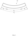
- FIG. 1 is a side view illustrating a state of an electrode assembly before a swelling phenomenon occurs according to a first embodiment of the present invention
- FIG. 2 is a side view illustrating a state of the electrode assembly after the swelling phenomenon according to the first embodiment of the present invention.
- An electrode assembly according to the present invention may have a structure in which a positive electrode, a separator, and a negative electrode are alternately disposed.
- the positive electrode may include a positive electrode collector and a positive electrode active material layer formed on both surfaces of the positive electrode collector
- the negative electrode may include a negative electrode collector and a negative electrode active material layer formed on both surfaces of the negative electrode collector.
- the separator may be disposed between the positive electrode and the negative electrode.
- the electrode assembly according to the present invention may be an electrode assembly used for a polymer electrolyte secondary battery.
- the electrode assembly according to the present invention may further include a polymer electrolyte layer disposed between the positive electrode and the separator and between the negative electrode and the separator.
- a polymer electrolyte forming the polymer electrolyte layer may be a polymer solid electrolyte.
- the polymer electrolyte may be a gel electrolyte in which a plasticizer is added to the polymer solid electrolyte.
- a curved surface may be formed on the electrode assembly according to the present invention.
- the curved surface may have a predetermined curvature radius. That is, as illustrated in FIG. 1 , the curved surface of the electrode assembly 10 before a swelling phenomenon occurs may have a mean curvature radius R a on the entire curved surface.
- the curved surface of the electrode assembly 10 may be divided into a central portion and both ends.
- the central portion and each of both the ends of the curved surface may have curvature radii R c and R e , respectively.
- R c and R e may be equal to or different from each other.
- R c , R e , and R a may be equal to each other.
- all of the curvature radii of both ends of the curved surface have the curvature radius R e in FIG. 1 , this does not mean that the curvature radii of both the ends of the curved surface are necessarily the same. That is, the curvature radius of one end of the curved surface and the curvature radius of the other end of the curved surface may be different from each other according to process characteristics of the curved surface in a process of forming the curved surface.
- a formation step of charging and discharging the secondary battery several times to allow the secondary battery to be in a usable state may be performed.
- a phenomenon in which an initial curvature radius of the electrode assembly varies may additionally occur. That is, as the swelling phenomenon occurs, a curvature radius of the curved surface of the electrode assembly after the swelling phenomenon occurs may become larger than that of the curved surface of the electrode assembly before the swelling phenomenon occurs. Particularly, as the swelling phenomenon occurs, the curved surface of the electrode assembly may be relatively flat. This may be understood that the curvature radius of the curved surface increases due to the swelling phenomenon.
- the flattening of the curved surface of the electrode assembly due to the swelling phenomenon may be relatively larger at both ends of the curved surface than at the central portion of the curved surface. This may be understood that a variation in curvature radius at each of both ends of the curved surface is larger than that in curvature radius at the central portion of the curved surface.
- An object of the present invention is to solve the problem in which the initially intended characteristics (i.e., a curvature radius) of the curved surface of the electrode assembly are not achieved due to the swelling phenomenon.
- a method for manufacturing the electrode assembly according to the first embodiment of the present invention may include a forming step of forming an electrode assembly 10 having a curved surface and a charging/discharging step of charging and discharging the electrode assembly 10 several times.
- the curved surface may be formed so that a mean curvature radius R a of the curved surface before the charging/discharging step is less than a mean curvature radius r a of the curved surface after the charging/discharging step.
- r a may be a mean curvature radius, which is finally intended, of the electrode assembly.
- the curved surface of the electrode assembly before the swelling phenomenon occurs is formed to be relatively large in consideration of a phenomenon in which the curved surface of the electrode assembly is relatively flat by the swelling phenomenon.
- the curvature radius of the electrode assembly after the formation step may match the curvature radius of the electrode assembly, which is originally designed.
- a curvature radius R e at an end of the curved surface before the charging/discharging step may be less than a curvature radius R c at the central portion of the curved surface before the charging/discharging step.
- the curvature radius of the curved surface of the electrode assembly may increase by the swollen shape of the electrode assembly having the curved surface (e.g., the curved surface becomes relatively flat).
- the increase in curvature radius is relatively larger at both ends of the curved surface than at the central portion of the curved surface.
- the curvature radius R e may be formed to be smaller than the curvature radius R c so that a difference between the curvature radii r e and r c is smaller than a difference between the curvature radii R e an R c to manufacture the electrode assembly on which a curved surface having a constant curvature radius is formed.
- the curvature radius R e may be formed to have a ratio within a predetermined range with respect to the curvature radius R c .
- the curvature radius R e may be 0.95 times to 0.99 times of the curvature radius R c .
- the curvature radius R e is less than 0.95 times of the curvature radius R c , since the curvature radius r e is still less than the curvature radius r c after the swelling phenomenon occurs, both the ends of the curved surface may be excessively curved.
- the curvature radius R e exceeds 0.99 times of the curvature radius R c , since the curvature radius is recessively larger than the curvature radius r c after the swelling phenomenon occurs, both ends of the curved surface become excessively flat, and thus, the problem according to the related art may not be solved. More preferably, the curvature radius R e may be 0.96 times to 0.98 times of the curvature radius R c .
- the curvature radius R e may be formed to have a difference within a predetermined range with to the curvature radius R c .
- the curvature radius R e may be less 4 mm to 8 mm than the curvature radius R c .
- the curvature radius R e is less than the curvature radius R c by less than 4 mm, since the curvature radius is recessively larger than the curvature radius r c after the swelling phenomenon occurs, both ends of the curved surface become excessively flat, and thus, the problem according to the related art may not be solved.
- both the ends of the curved surface may be excessively curved. More preferably, the curvature radius R e may be less 5mm to 7 mm than the curvature radius R c .
- the top and bottom surfaces of the electrode assembly may be pressed together with each other by the upper pressing device and the lower pressing device.
- a surface of the upper pressing device, which presses the top surface of the electrode assembly may have a concave surface or may be provided with only the concave surface.
- a surface of the lower pressing device, which presses the bottom surface of the electrode assembly may have a convex surface.
- the surface of the lower pressing device, which presses the bottom surface of the electrode assembly may have a convex surface or may be provided with only the convex surface.
- the surface of the lower pressing device which presses the bottom surface of the electrode assembly
- the surface of the lower pressing device, which presses the bottom surface of the electrode assembly may have all of the convex surface and the flat surface.
- the flat surface may be disposed at a central portion of the surface of the lower pressing device, which presses the bottom surface of the electrode assembly, and the convex surface may be disposed at the peripheral portion of the surface of the lower pressing device.
- the electrode assembly may be pressed under conditions of a specific temperature, pressure, and time.
- the electrode assembly may be pressed at a temperature of 80 degrees to 90 degrees Celsius and a pressure of 8 kgf/cm 2 to 12 kgf/cm 2 for a time period of 4 minutes to 6 minutes.
- the electrode assembly may be pressed under conditions of a temperature of 85 degree and a pressure of 10 kgf/cm 2 for a time period of 5 minutes.
- FIG. 3 is a side view illustrating an electrode of an electrode assembly according to a second embodiment of the present invention.
- the second embodiment of the present invention is also intended to solve the problem caused by a variation in curvature radius of the curved surface of the electrode assembly due to the swelling phenomenon.
- an electrode 11 constituting an electrode assembly may include a collector 12 and an electrode active material layer 14 applied to each of both surfaces of the collector 12.
- a curved surface having a shape corresponding to that of the curved surface of the electrode assembly may be formed on the electrode 11 constituting the electrode assembly.
- the electrode active material layer 14 may be applied to a first surface (i.e., a top surface of a collector 12 in FIG. 3 ) provided to face the inside of the curved surface formed on the electrode 11 with respect to the collector 12 and a second surface (i.e., a bottom surface of the collector 12 in FIG. 3 ) provided to face the outside of the curved surface formed on the electrode 11 with respect to the collector 12.
- the electrode active material layer applied to the first surface of the electrode 11 of the electrode assembly according to the second embodiment of the present invention may have a thickness t 1 different from a thickness t 2 of the electrode active material layer applied to the second surface.
- the thickness t 1 may be less than the thickness t 2 .
- the electrode active material layer may be applied so that the thickness t 1 is less than the thickness t 2 to prevent the electrode from being flattened when a swelling phenomenon occurs.
- the electrode active material layer may be applied so that the thickness t 1 is less than the thickness t 2 to prevent the electrode from being flattened when a swelling phenomenon occurs.
- the thickness t 1 may also have a ratio within a predetermined range with respect to the thickness t 2 .
- the thickness t 1 may be 0.7 times to 0.9 times of the thickness t 2 .
- the thickness of the electrode active material layer applied to the second surface may be excessively large, and thus, the electrode assembly may be more curved.
- the thickness t 1 exceeds 0.9 times of the thickness t 2 , the flattening of the electrode assembly may be effectively prevented.
- FIG. 4 is a side view illustrating an electrode of an electrode assembly according to a third embodiment of the present invention.
- the third embodiment of the present invention is also intended to solve the problem caused by a variation in curvature radius of the curved surface of the electrode assembly due to the swelling phenomenon.
- an electrode 11 constituting the electrode assembly may include a collector 12 and an electrode active material layer 14 applied to each of both surfaces of the collector 12. Also, since the electrode 11 having a curved surface and first and second surfaces coated with the electrode active material layer are basically the same as those according to the second example of the present invention and FIG. 3 , their descriptions are derived from those according to the second embodiment of the present invention.
- a non-coating portion which is not coated with the electrode active material layer, may be formed between the electrode active material layers on the electrode of the electrode assembly according to the third embodiment of the present invention. As illustrated in FIG. 4 , the non-coating portion 16 may be formed on the first surface.
- the non-coating portion may be formed on the first surface to form an empty space between the electrode active material layers applied to the first surface.
- the empty space between the electrode active material layers may prevent the electrode assembly from being flattened again. That is, when the electrode active material layer is also applied to the non-coating portion of the first surface, since a curved surface is formed on the electrode assembly, the electrode active material layer applied on the corresponding non-coating layer of the first surface may be pressed. In this case, the electrode active layer applied to the corresponding non-coating portion of the first surface may be expanded by restoring force. Thus, the electrode assembly may intend to be expanded again.
- the non-coating portion is formed on the first surface to minimize the tendency of the electrode active material layer applied to the first surface to be expanded again by the restoring force, thereby maintaining the electrode assembly having the curved surface as it is.
- the non-coating portion 16 may be provided in plurality.
- FIG. 4 illustrates a case in which two non-coating portions 16 are formed.
- the electrode active material layers applied to the first surface may be spaced apart from each other by the non-coating portion 16. Thus, a plurality of electrode active material layers may be formed on the first surface.
- the electrode active material layer applied to the collector 12 may have a predetermined length L.
- the non-coating portion 16 is formed on the first surface, and the plurality of electrode active material layers may be formed on the first surface by the non-coating portion 16.
- each of the plurality of active material layers formed on the first surface may have a length.
- a length of the electrode active material layer, which is formed on the center of the first surface, of the plurality of active material layers formed on the first surface is called L c
- a length of the electrode active material layer formed on each of both ends of the first surface is called L e .
- the length (i.e., L e ) of the electrode active material layer, which is formed on one end or each of both ends of the first surface, of the plurality of electrode active material layers applied to the first surface may have a ratio within a predetermined range with respect to the total length (i.e., L) of the plurality of electrode active material layer applied to the first surface.
- the length L e may be 0.05 times to 0.3 times of the length L.
- both ends of the electrode assembly When the length L e is less than 0.05 times of the length L, both ends of the electrode assembly may be excessively curved after the swelling phenomenon occurs. When the length L e exceeds 0.05 times of the length L, both ends of the electrode assembly may be excessively flat after the swelling phenomenon occurs, and thus, it may be difficult to solve the problem according to the related art.
- the two non-coating portions 16 are formed on the first surface, and the electrode active material layers applied to the first surface may be spaced apart from each other by the two non-coating portions to form three electrode active material layers.
- a length (i.e., L c ) of the electrode active material layer, which is formed at a center of the first surface, of the plurality of electrode active material layers applied to the first surface may have a ratio within a predetermined range with respect to the total length (i.e., L) of the plurality of electrode active material layer applied to the first surface.
- the length L c may be 0.4 times to 0.9 times of the length L.
- both ends of the electrode assembly may be excessively flat after the swelling phenomenon occurs.
- both ends of the electrode assembly may be excessively curved after the swelling phenomenon occurs, and thus, it may be difficult to solve the problem according to the related art.
- the electrode assembly according to the present invention may be an electrode assembly inserted into a can or a pouch of a can type secondary battery or a pouch type secondary battery. That is, the present invention may be an invention related to the can type secondary battery or the pouch type secondary battery.
- the pouch accommodating the electrode assembly may have a multilayered structure respectively made of a plurality of materials.
- the pouch may include an aluminum layer, and a polyolefin resin layer provided on the upper and lower portions of the aluminum layer, respectively.
- polyolefin may be polypropylene.
- an electrode assembly was pressed by a pressing presser to form a curved surface of each of top and bottom surfaces of the electrode assembly.
- a curvature radius R e (left) of a left end was 195 mm
- a curvature radius R e (right) of a right end was 195 mm
- a curvature radius R c of a central portion was 200 mm.
- An electrode assembly was manufactured in the same method as in Example 1, except that, in curvature radii of ends of a curved surface of the electrode assembly, a curvature radius R e (left) of a left end was 194 mm, a curvature radius R e (right) of a right end was 195 mm, and a curvature radius R c of a central portion of the curved surface was 201 mm.
- An electrode assembly was manufactured in the same method as in Example 1, except that, in curvature radii of ends of a curved surface of the electrode assembly, a curvature radius R e (left) of a left end was 195 mm, a curvature radius R e (right) of a right end was 196 mm, and a curvature radius R c of a central portion of the curved surface was 200 mm.
- An electrode assembly was manufactured in the same method as in Example 1, except that, in curvature radii of ends of a curved surface of the electrode assembly, a curvature radius R e (left) of a left end was 188 mm, a curvature radius R e (right) of a right end was 188 mm, and a curvature radius R c of a central portion of the curved surface was 200 mm.
- An electrode assembly was manufactured in the same method as in Example 1, except that, in curvature radii of ends of a curved surface of the electrode assembly, a curvature radius R e (left) of a left end was 201 mm, a curvature radius R e (right) of a right end was 201 mm, and a curvature radius R c of a central portion of the curved surface was 197 mm.
- Each of the electrode assemblies manufactured according to Examples and Comparative Examples was repeatedly changed and discharged to perform a formation process.
- the formation process was performed through charging and discharging 300 times at a temperature of 45°C.
- the charging of the formation process was performed under constant current of 1.0 C and a voltage of 4.4 V, and when the charging is completed, current was 122 mA.
- the discharging of the formation process was performed under constant current of 1.0 C, and when the discharging is completed, a voltage was 3.0 V.
- the curvature radius of the curved surface formed on the electrode assembly was measured.
- the curvature radius of the curved surface of the electrode assembly measured before and after the formation process was summarized in Table 1 below.
- a curvature radius of a left end was expressed as r e (left)
- a curvature radius of a right end was expressed as r e (right)
- a curvature radius of a central portion of the curved surface was expressed as r c .
- the curvature radius of the electrode assembly is uniformly formed over the entire area of the ends and the central portion of the curved surface.
- a difference between the curvature radii r e and r c is up to 3 mm.
- a difference between the curvature radii r e and r c is up to 6 mm.
- Item 1 An electrode assembly having a curved surface, wherein a curvature radius (R e ) of each of ends of the curved surface is less than a curvature radius (R c ) of a central portion of the curved surface.
- Item 2 The electrode assembly of item 1, wherein the curvature radius R e is 0.95 times to 0.99 times of the curvature radius R c .
- An electrode assembly having a curved surface comprising: a plurality of electrodes, each of which has a shape corresponding to that of the curved surface formed on the electrode assembly, wherein at least one electrode comprises: a collector; and an electrode active material layer applied to each of first and second surfaces of the collector, wherein the first surface is disposed to face the inside of the curved surface with respect to the collector, the second surface is disposed to face the outside of the curved surface with respect to the collector, and a thickness (t 1 ) of the electrode active material layer applied to the first surface is less than a thickness (t 2 ) of the electrode active material layer applied to the second surface.
- Item 4 The electrode assembly of item 3, wherein the thickness t 1 is 0.7 times to 0.9 times of the thickness t 2 .
- An electrode assembly having a curved surface comprising: a plurality of electrodes, each of which has a shape corresponding to that of the curved surface formed on the electrode assembly, wherein at least one electrode comprises: a collector; and an electrode active material layer applied to each of first and second surfaces of the collector, wherein the first surface is disposed to face the inside of the curved surface with respect to the collector, the second surface is disposed to face the outside of the curved surface with respect to the collector, and a non-coating portion that is not coated with the electrode active material layer is disposed between the electrode active material layers applied to the first surface.
- Item 6 The electrode assembly of item 5, wherein the non-coating portion is provided in plurality, the electrode active material applied to the first surface is divided to be spaced apart from each other by the non-coating portions to form a plurality of electrode active material layers on the first surface, and a length (L e ) of the electrode active material layer, which is formed on one end or each of both ends of the first surface, of the plurality of electrode active material layers applied to the first surface is 0.05 times to 0.3 times of the total length (L) of the plurality of electrode active material layers.
- Item 7 The electrode assembly of item 5, wherein the non-coating portion is provided in two, the electrode active material applied to the first surface is divided to be spaced apart from each other by the two non-coating portions to form three electrode active material layers on the first surface, and a length (L c ) of the electrode active material layer, which is formed at a center of the first surface, of the three electrode active material layers applied to the first surface is 0.4 times to 0.9 times of the total length (L) of the three electrode active material layers.
- Item 8 A method for manufacturing an electrode assembly, the method comprising: a forming step of forming the electrode assembly having a curved surface; and a charging/discharging step of charging and discharging the electrode assembly several times, wherein, in the forming step, a curvature radius R e is less than a curvature radius R c so that a difference between the curvature radius (r e ) of the end of the curved surface and the curvature radius (r c ) of the central portion of the curved surface after the charging/discharging step is less than a difference between the curvature radius (R e ) of an end of the curved surface and the curvature radius (R c ) of a central portion of the curved surface before the charging/discharging step.
- Item 9 The method of item 8, wherein the curvature radius R e is 0.95 times to 0.99 times of the curvature radius R c .
- Item 10 A method for manufacturing an electrode assembly, the method comprising: a forming step of forming the electrode assembly having a curved surface; and a charging/discharging step of charging and discharging the electrode assembly several times, wherein, in the forming step, mean curvature radii R a and r a are formed so that the mean curvature radius (R a ) of the curved surface before the charging/discharging step is less than the mean curvature radius (r a ) of the curved surface after the charging/discharging step.
- An electrode assembly having a curved surface comprising: a positive electrode comprising a positive electrode collector and a positive electrode active material layer formed on each of both surfaces of the positive electrode collector; a negative electrode comprising a negative electrode collector and a negative electrode active material layer formed on each of both surfaces of the negative electrode collector; a separator disposed between the positive electrode and the negative electrode; and a polymer electrolyte layer disposed between the positive electrode and the separator and between the negative electrode and the separator, wherein a curvature radius (R e ) each of ends of the curved surface is less than a curvature radius (R c ) of a central portion of the curved surface.
- Item 12 The electrode assembly of item 11, wherein the polymer electrolyte layer comprises a gel electrolyte in which a plasticizer is added to a polymer solid electrolyte.
- a method for manufacturing an electrode assembly comprising: a forming step of forming the electrode assembly having a curved surface; and a charging/discharging step of charging and discharging the electrode assembly several times, wherein, in the forming step, a top surface of the electrode assembly is pressed by an upper pressing device having a concave surface for pressing the top surface of the electrode assembly, and in the forming step, mean curvature radii R a and r a are formed so that the mean curvature radius (R a ) of the curved surface before the charging/discharging step is less than the mean curvature radius (r a ) of the curved surface after the charging/discharging step.
- Item 14 The method of item 13, wherein, in the forming step, a bottom surface of the electrode assembly is pressed by a lower pressing device having a convex surface for pressing the bottom surface of the electrode assembly.
- Item 15 The method of item 13, wherein, in the forming step, a bottom surface of the electrode assembly is pressed by a lower pressing device having a flat surface for pressing the bottom surface of the electrode assembly.
- Item 16 The method of item 13, wherein, in the forming step, the electrode assembly is pressed under conditions of a temperature of 80 degrees to 90 degrees Celsius and a pressure of 8 kgf/cm 2 to 12 kgf/cm 2 for a time period of 4 minutes to 6 minutes.
- a secondary battery comprising: the electrode assembly of item 1; and a pouch exterior accommodating the electrode assembly.
Landscapes
- Chemical & Material Sciences (AREA)
- Chemical Kinetics & Catalysis (AREA)
- Electrochemistry (AREA)
- General Chemical & Material Sciences (AREA)
- Engineering & Computer Science (AREA)
- Manufacturing & Machinery (AREA)
- Physics & Mathematics (AREA)
- Condensed Matter Physics & Semiconductors (AREA)
- Dispersion Chemistry (AREA)
- General Physics & Mathematics (AREA)
- Inorganic Chemistry (AREA)
- Materials Engineering (AREA)
- Battery Electrode And Active Subsutance (AREA)
- Secondary Cells (AREA)
Abstract
Description
- The present application claims the benefit of the priority of
Korean Patent Application Nos. 10-2017-0090977, filed on July 18, 2017 10-2018-0080734, filed on July 11, 2018 - The present invention relates to an electrode assembly, a secondary battery including the electrode assembly, and a method for manufacturing the electrode assembly, and more particularly, to an electrode assembly having a structure that is minimized in deformation due to a swelling phenomenon of the electrode assembly, a secondary battery including the electrode assembly, and a method for manufacturing the electrode assembly.
- Secondary batteries capable of being repeatedly chargeable and dischargeable may be provided in various types. In general, such a secondary battery includes an electrode assembly having a structure in which an electrode and a separator are alternately stacked.
- The demand and type of electronic devices are increasing, and in particular, as the demand of electronic devices having an irregular shape, which deviates from the typical simple shape, increases, a secondary battery mounted on an electronic device having an irregular shape is also increasingly required to have an irregular shape.
- The secondary battery having the irregular shape may have, for example, a curved surface. The secondary battery having the curved surface is often manufactured so as to form a certain radius of curvature.
- The assembled secondary battery is subjected to a formation step of charging and discharging the secondary battery several times in order to form the secondary battery before the shipment. In the formation step, a swelling phenomenon in which the electrode assembly and the secondary battery are swollen to increase in volume of the secondary battery may occur generally.
- As the swelling phenomenon occurs, the electrode assembly and the secondary battery may be deformed from an initially assembled form. Thus, there has been a problem that the secondary having an originally intended shape is not manufactured. Particularly, in case of a secondary battery having a curved surface having a constant curvature radius, an initial curvature radius and a curvature radius after the swelling are different from each other due to the swelling phenomenon to deteriorate assemblability and storage ability of the secondary battery with respect to electronic devices.
- For example, in case of an electrode assembly having a curved surface as the assembled electrode assembly, the entire curvature radius of the curved surface after the swelling phenomenon occurs is greater than the entire curvature radius of the curved surface before the swelling phenomenon occurs (i.e., the curved surface formed on the electrode assembly is relatively flat due to the swelling phenomenon).
- Particularly, deformation of the curved surface largely occurs at both ends of the curved surface. That is, even though the electrode assembly is assembled so that a central portion and each of both ends of the curved surface have the same curvature radius, the curvature radius at both ends of the curved surface may be greater than that at the central portion after the swelling (i.e., each of both ends of the electrode assembly is relatively more flat due to the swelling phenomenon).
- Thus, an object to be solved by the present invention is to improve assemblability and storage ability of a secondary battery having a curved surface with respect to electronic devices by manufacturing an electrode assembly in consideration of deformation of the electrode assembly and the secondary battery due to a swelling phenomenon.
- According to a first aspect of the present invention for achieving the above object, provided is an electrode assembly having a curved surface, wherein a curvature radius (Re) of each of ends of the curved surface is less than a curvature radius (Rc) of a central portion of the curved surface.
- The curvature radius Re may be 0.95 times to 0.99 times of the curvature radius Rc.
- According to a second aspect of the present invention for achieving the above object, an electrode assembly having a curved surface includes: a plurality of electrodes, each of which has a shape corresponding to that of the curved surface formed on the electrode assembly, wherein at least one electrode includes: a collector; and an electrode active material layer applied to each of first and second surfaces of the collector, wherein the first surface is disposed to face the inside of the curved surface with respect to the collector, the second surface is disposed to face the outside of the curved surface with respect to the collector, and a thickness of the electrode active material layer applied to the first surface is less than a thickness of the electrode active material layer applied to the second surface.
- The thickness t1 of the electrode active material layer applied to the first surface is 0.7 times to 0.9 times of the thickness t2 of the electrode active material layer applied to the second surface.
- According to a third aspect of the present invention for achieving the above object, an electrode assembly having a curved surface includes: a plurality of electrodes, each of which has a shape corresponding to that of the curved surface formed on the electrode assembly, wherein at least one electrode includes: a collector; and an electrode active material layer applied to each of first and second surfaces of the collector, wherein the first surface is disposed to face the inside of the curved surface with respect to the collector, the second surface is disposed to face the outside of the curved surface with respect to the collector, and a non-coating portion that is not coated with the electrode active material layer is disposed between the electrode active material layers applied to the first surface.
- The non-coating portion may be provided in plurality, the electrode active material applied to the first surface may be divided to be spaced apart from each other by the non-coating portions to form a plurality of electrode active material layers on the first surface, and a length of the electrode active material layer, which is formed on one end or each of both ends of the first surface, of the plurality of electrode active material layers applied to the first surface may be 0.05 times to 0.3 times of the total length of the plurality of electrode active material layers.
- The non-coating portion may be provided in two, the electrode active material applied to the first surface may be divided to be spaced apart from each other by the two non-coating portions to form three electrode active material layers on the first surface, and a length of the electrode active material layer, which is formed at a center of the first surface, of the three electrode active material layers applied to the first surface may be 0.4 times to 0.9 times of the total length of the three electrode active material layers.
- According to a fourth aspect of the present invention for achieving the above object, a method for manufacturing an electrode assembly includes: a forming step of forming the electrode assembly having a curved surface; and a charging/discharging step of charging and discharging the electrode assembly several times, wherein, in the forming step, a curvature radius Re is less than a curvature radius Rc so that a difference between the curvature radius (re) of the end of the curved surface and the curvature radius (rc) of the central portion of the curved surface after the charging/discharging step is less than a difference between the curvature radius (Re) of an end of the curved surface and the curvature radius (Rc) of a central portion of the curved surface before the charging/discharging step.
- The curvature radius Re may be 0.95 times to 0.99 times of the curvature radius Rc.
- According to a fifth aspect of the present invention for achieving the above object, a method for manufacturing an electrode assembly includes: a forming step of forming the electrode assembly having a curved surface; and a charging/discharging step of charging and discharging the electrode assembly several times, wherein, in the forming step, mean curvature radii Ra and ra are formed so that the mean curvature radius (Ra) of the curved surface before the charging/discharging step is less than the mean curvature radius (ra) of the curved surface after the charging/discharging step.
- According to a sixth aspect of the present invention for achieving the above object, an electrode assembly having a curved surface includes: a positive electrode comprising a positive electrode collector and a positive electrode active material layer formed on each of both surfaces of the positive electrode collector; a negative electrode comprising a negative electrode collector and a negative electrode active material layer formed on each of both surfaces of the negative electrode collector; a separator disposed between the positive electrode and the negative electrode; and
- a polymer electrolyte layer disposed between the positive electrode and the separator and between the negative electrode and the separator, wherein a curvature radius (Re) each of ends of the curved surface is less than a curvature radius (Rc) of a central portion of the curved surface.
- The polymer electrolyte layer may include a gel electrolyte in which a plasticizer is added to a polymer solid electrolyte.
- According to a seventh aspect of the present invention for achieving the above object, a method for manufacturing an electrode assembly includes: a forming step of forming the electrode assembly having a curved surface; and a charging/discharging step of charging and discharging the electrode assembly several times, wherein, in the forming step, a top surface of the electrode assembly is pressed by an upper pressing device having a concave surface for pressing the top surface of the electrode assembly, and in the forming step, mean curvature radii Ra and ra are formed so that the mean curvature radius (Ra) of the curved surface before the charging/discharging step is less than the mean curvature radius (ra) of the curved surface after the charging/discharging step.
- In the forming step, a bottom surface of the electrode assembly may be pressed by a lower pressing device having a convex surface for pressing the bottom surface of the electrode assembly.
- In the forming step, a bottom surface of the electrode assembly may be pressed by a lower pressing device having a flat surface for pressing the bottom surface of the electrode assembly.
- In the forming step, the electrode assembly may be pressed under conditions of a temperature of 80 degrees to 90 degrees Celsius and a pressure of 8 kgf/cm2 to 12 kgf/cm2 for a time period of 4 minutes to 6 minutes.
- According to the present invention, the electrode assembly may be manufactured in consideration of the deformation of the electrode assembly and the secondary battery due to the swelling phenomenon to improve the assemblability and the storage ability of the secondary battery having the curved surface with respect to the electronic devices.
-
-
FIG. 1 is a side view illustrating a state of an electrode assembly before a swelling phenomenon occurs according to a first embodiment of the present invention. -
FIG. 2 is a side view illustrating a state of the electrode assembly after the swelling phenomenon according to th first embodiment of the present invention. -
FIG. 3 is a side view illustrating an electrode of an electrode assembly according to a second embodiment of the present invention. -
FIG. 4 is a side view illustrating an electrode of an electrode assembly according to a third embodiment of the present invention. - Hereinafter, an electrode and a method for manufacturing the electrode assembly according to the present invention will be described with reference to the accompanying drawings.
-
FIG. 1 is a side view illustrating a state of an electrode assembly before a swelling phenomenon occurs according to a first embodiment of the present invention, andFIG. 2 is a side view illustrating a state of the electrode assembly after the swelling phenomenon according to the first embodiment of the present invention. - An electrode assembly according to the present invention may have a structure in which a positive electrode, a separator, and a negative electrode are alternately disposed. Here, the positive electrode may include a positive electrode collector and a positive electrode active material layer formed on both surfaces of the positive electrode collector, and the negative electrode may include a negative electrode collector and a negative electrode active material layer formed on both surfaces of the negative electrode collector. The separator may be disposed between the positive electrode and the negative electrode.
- Also, the electrode assembly according to the present invention may be an electrode assembly used for a polymer electrolyte secondary battery. Thus, the electrode assembly according to the present invention may further include a polymer electrolyte layer disposed between the positive electrode and the separator and between the negative electrode and the separator.
- A polymer electrolyte forming the polymer electrolyte layer may be a polymer solid electrolyte. Alternatively, the polymer electrolyte may be a gel electrolyte in which a plasticizer is added to the polymer solid electrolyte.
- As illustrated in
FIGS. 1 and2 , a curved surface may be formed on the electrode assembly according to the present invention. - Here, the curved surface may have a predetermined curvature radius. That is, as illustrated in
FIG. 1 , the curved surface of theelectrode assembly 10 before a swelling phenomenon occurs may have a mean curvature radius Ra on the entire curved surface. - As illustrated in
FIG. 1 , the curved surface of theelectrode assembly 10 may be divided into a central portion and both ends. Thus, the central portion and each of both the ends of the curved surface may have curvature radii Rc and Re, respectively. Rc and Re may be equal to or different from each other. When Rc and Re are equal to each other, Rc, Re, and Ra may be equal to each other. Also, although all of the curvature radii of both ends of the curved surface have the curvature radius Re inFIG. 1 , this does not mean that the curvature radii of both the ends of the curved surface are necessarily the same. That is, the curvature radius of one end of the curved surface and the curvature radius of the other end of the curved surface may be different from each other according to process characteristics of the curved surface in a process of forming the curved surface. - In general, after the electrode assembly is manufactured, in order to realize formation of the secondary battery, a formation step of charging and discharging the secondary battery several times to allow the secondary battery to be in a usable state may be performed.
- However, in the formation process, a swelling phenomenon in which the electrode assembly within the secondary battery increases in volume may occur. Since the electrode assembly increases in volume due to the swelling phenomenon, the electrode assembly may be changed in shape before and after the swelling phenomenon occurs. This leads to distortion in shape of the electrode assembly and the secondary battery.
- When the swelling phenomenon occurs in the electrode assembly having a curved surface, a phenomenon in which an initial curvature radius of the electrode assembly varies may additionally occur. That is, as the swelling phenomenon occurs, a curvature radius of the curved surface of the electrode assembly after the swelling phenomenon occurs may become larger than that of the curved surface of the electrode assembly before the swelling phenomenon occurs. Particularly, as the swelling phenomenon occurs, the curved surface of the electrode assembly may be relatively flat. This may be understood that the curvature radius of the curved surface increases due to the swelling phenomenon.
- Also, the flattening of the curved surface of the electrode assembly due to the swelling phenomenon may be relatively larger at both ends of the curved surface than at the central portion of the curved surface. This may be understood that a variation in curvature radius at each of both ends of the curved surface is larger than that in curvature radius at the central portion of the curved surface.
- An object of the present invention is to solve the problem in which the initially intended characteristics (i.e., a curvature radius) of the curved surface of the electrode assembly are not achieved due to the swelling phenomenon.
- Referring to
FIGS. 1 and2 , a method for manufacturing the electrode assembly according to the first embodiment of the present invention may include a forming step of forming anelectrode assembly 10 having a curved surface and a charging/discharging step of charging and discharging theelectrode assembly 10 several times. In the forming step, the curved surface may be formed so that a mean curvature radius Ra of the curved surface before the charging/discharging step is less than a mean curvature radius ra of the curved surface after the charging/discharging step. Here, ra may be a mean curvature radius, which is finally intended, of the electrode assembly. - According to the first embodiment of the present invention, the curved surface of the electrode assembly before the swelling phenomenon occurs is formed to be relatively large in consideration of a phenomenon in which the curved surface of the electrode assembly is relatively flat by the swelling phenomenon. Thus, the curvature radius of the electrode assembly after the formation step may match the curvature radius of the electrode assembly, which is originally designed.
- According to a modified example of the first embodiment of the present invention, in the forming step, a curvature radius Re at an end of the curved surface before the charging/discharging step may be less than a curvature radius Rc at the central portion of the curved surface before the charging/discharging step.
- As described above, the curvature radius of the curved surface of the electrode assembly may increase by the swollen shape of the electrode assembly having the curved surface (e.g., the curved surface becomes relatively flat). The increase in curvature radius is relatively larger at both ends of the curved surface than at the central portion of the curved surface.
- Thus, according to the modified example of the first embodiment of the present invention, in the forming step of forming the curved surface of the electrode assembly, the curvature radius Re may be formed to be smaller than the curvature radius Rc so that a difference between the curvature radii re and rc is smaller than a difference between the curvature radii Re an Rc to manufacture the electrode assembly on which a curved surface having a constant curvature radius is formed.
- Here, the curvature radius Re may be formed to have a ratio within a predetermined range with respect to the curvature radius Rc. For example, the curvature radius Re may be 0.95 times to 0.99 times of the curvature radius Rc. When the curvature radius Re is less than 0.95 times of the curvature radius Rc, since the curvature radius re is still less than the curvature radius rc after the swelling phenomenon occurs, both the ends of the curved surface may be excessively curved. Also, when the curvature radius Re exceeds 0.99 times of the curvature radius Rc, since the curvature radius is recessively larger than the curvature radius rc after the swelling phenomenon occurs, both ends of the curved surface become excessively flat, and thus, the problem according to the related art may not be solved. More preferably, the curvature radius Re may be 0.96 times to 0.98 times of the curvature radius Rc.
- Also, the curvature radius Re may be formed to have a difference within a predetermined range with to the curvature radius Rc. For example, the curvature radius Re may be less 4 mm to 8 mm than the curvature radius Rc. When the curvature radius Re is less than the curvature radius Rc by less than 4 mm, since the curvature radius is recessively larger than the curvature radius rc after the swelling phenomenon occurs, both ends of the curved surface become excessively flat, and thus, the problem according to the related art may not be solved. Also, when the curvature radius Re is less than the curvature radius Rc by more than 8 mm, since the curvature radius re is still small than the curvature radius rc after the swelling phenomenon occurs, both the ends of the curved surface may be excessively curved. More preferably, the curvature radius Re may be less 5mm to 7 mm than the curvature radius Rc.
- In the forming step according to the first embodiment of the present invention, the top and bottom surfaces of the electrode assembly may be pressed together with each other by the upper pressing device and the lower pressing device. A surface of the upper pressing device, which presses the top surface of the electrode assembly, may have a concave surface or may be provided with only the concave surface. Also, a surface of the lower pressing device, which presses the bottom surface of the electrode assembly, may have a convex surface. Alternatively, the surface of the lower pressing device, which presses the bottom surface of the electrode assembly, may have a convex surface or may be provided with only the convex surface. On the other hand, the surface of the lower pressing device, which presses the bottom surface of the electrode assembly, may have a flat surface or may be provided with only the flat surface. Alternatively, the surface of the lower pressing device, which presses the bottom surface of the electrode assembly, may have all of the convex surface and the flat surface. For example, the flat surface may be disposed at a central portion of the surface of the lower pressing device, which presses the bottom surface of the electrode assembly, and the convex surface may be disposed at the peripheral portion of the surface of the lower pressing device.
- Also, in the forming step, the electrode assembly may be pressed under conditions of a specific temperature, pressure, and time. In the forming step, the electrode assembly may be pressed at a temperature of 80 degrees to 90 degrees Celsius and a pressure of 8 kgf/cm2 to 12 kgf/cm2 for a time period of 4 minutes to 6 minutes. For example, in the forming step, the electrode assembly may be pressed under conditions of a temperature of 85 degree and a pressure of 10 kgf/cm2 for a time period of 5 minutes.
- The above-described contents with respect to the forming step, the upper pressing device and the lower pressing device may be equally applied to following second and third embodiments of the present invention.
-
FIG. 3 is a side view illustrating an electrode of an electrode assembly according to a second embodiment of the present invention. - Like the first embodiment of the present invention, the second embodiment of the present invention is also intended to solve the problem caused by a variation in curvature radius of the curved surface of the electrode assembly due to the swelling phenomenon.
- Referring to
FIG. 3 , anelectrode 11 constituting an electrode assembly may include acollector 12 and an electrodeactive material layer 14 applied to each of both surfaces of thecollector 12. - Since a curved surface is formed on the electrode assembly according to the present invention, a curved surface having a shape corresponding to that of the curved surface of the electrode assembly may be formed on the
electrode 11 constituting the electrode assembly. Thus, the electrodeactive material layer 14 may be applied to a first surface (i.e., a top surface of acollector 12 inFIG. 3 ) provided to face the inside of the curved surface formed on theelectrode 11 with respect to thecollector 12 and a second surface (i.e., a bottom surface of thecollector 12 inFIG. 3 ) provided to face the outside of the curved surface formed on theelectrode 11 with respect to thecollector 12. - Here, the electrode active material layer applied to the first surface of the
electrode 11 of the electrode assembly according to the second embodiment of the present invention may have a thickness t1 different from a thickness t2 of the electrode active material layer applied to the second surface. For example, the thickness t1 may be less than the thickness t2. - According to the second embodiment of the present invention, the electrode active material layer may be applied so that the thickness t1 is less than the thickness t2 to prevent the electrode from being flattened when a swelling phenomenon occurs.
- That is, the more the thickness of the electrode active material layer applied to the first surface provided to face the inside of the curved surface formed on the electrode with respect to the collector increases, the more the electrode tends to expand again due to the thickness of the electrode active material layer applied to the first surface. This adversely affects the shape maintenance of the electrode assembly having the curved surface. Thus, according to the second embodiment of the present invention, the electrode active material layer may be applied so that the thickness t1 is less than the thickness t2 to prevent the electrode from being flattened when a swelling phenomenon occurs.
- In similar to the first embodiment of the present invention, the thickness t1 may also have a ratio within a predetermined range with respect to the thickness t2. For example, the thickness t1 may be 0.7 times to 0.9 times of the thickness t2. When the thickness t1 is less than 0.7 times of the thickness t2, the thickness of the electrode active material layer applied to the second surface may be excessively large, and thus, the electrode assembly may be more curved. On the other hand, when the thickness t1 exceeds 0.9 times of the thickness t2, the flattening of the electrode assembly may be effectively prevented.
-
FIG. 4 is a side view illustrating an electrode of an electrode assembly according to a third embodiment of the present invention. - Like the first and embodiments of the present invention, the third embodiment of the present invention is also intended to solve the problem caused by a variation in curvature radius of the curved surface of the electrode assembly due to the swelling phenomenon.
- Referring to
FIG. 4 , anelectrode 11 constituting the electrode assembly may include acollector 12 and an electrodeactive material layer 14 applied to each of both surfaces of thecollector 12. Also, since theelectrode 11 having a curved surface and first and second surfaces coated with the electrode active material layer are basically the same as those according to the second example of the present invention andFIG. 3 , their descriptions are derived from those according to the second embodiment of the present invention. - A non-coating portion, which is not coated with the electrode active material layer, may be formed between the electrode active material layers on the electrode of the electrode assembly according to the third embodiment of the present invention. As illustrated in
FIG. 4 , thenon-coating portion 16 may be formed on the first surface. - According to the third embodiment of the present invention, the non-coating portion may be formed on the first surface to form an empty space between the electrode active material layers applied to the first surface. The empty space between the electrode active material layers may prevent the electrode assembly from being flattened again. That is, when the electrode active material layer is also applied to the non-coating portion of the first surface, since a curved surface is formed on the electrode assembly, the electrode active material layer applied on the corresponding non-coating layer of the first surface may be pressed. In this case, the electrode active layer applied to the corresponding non-coating portion of the first surface may be expanded by restoring force. Thus, the electrode assembly may intend to be expanded again.
- Thus, according to the third embodiment of the present invention, since the non-coating portion is formed on the first surface to minimize the tendency of the electrode active material layer applied to the first surface to be expanded again by the restoring force, thereby maintaining the electrode assembly having the curved surface as it is.
- Also, the
non-coating portion 16 may be provided in plurality.FIG. 4 illustrates a case in which twonon-coating portions 16 are formed. Also, the electrode active material layers applied to the first surface may be spaced apart from each other by thenon-coating portion 16. Thus, a plurality of electrode active material layers may be formed on the first surface. - The electrode active material layer applied to the
collector 12 may have a predetermined length L. Particularly, as described above, thenon-coating portion 16 is formed on the first surface, and the plurality of electrode active material layers may be formed on the first surface by thenon-coating portion 16. Thus, each of the plurality of active material layers formed on the first surface may have a length. In this specification, a length of the electrode active material layer, which is formed on the center of the first surface, of the plurality of active material layers formed on the first surface is called Lc, and a length of the electrode active material layer formed on each of both ends of the first surface is called Le. - In the
electrode 11 of the electrode assembly according to the third embodiment of the present invention, the length (i.e., Le) of the electrode active material layer, which is formed on one end or each of both ends of the first surface, of the plurality of electrode active material layers applied to the first surface may have a ratio within a predetermined range with respect to the total length (i.e., L) of the plurality of electrode active material layer applied to the first surface. For example, the length Le may be 0.05 times to 0.3 times of the length L. - When the length Le is less than 0.05 times of the length L, both ends of the electrode assembly may be excessively curved after the swelling phenomenon occurs. When the length Le exceeds 0.05 times of the length L, both ends of the electrode assembly may be excessively flat after the swelling phenomenon occurs, and thus, it may be difficult to solve the problem according to the related art.
- As described above, in the
electrode 11 of the electrode assembly according to third embodiment of the present invention, the twonon-coating portions 16 are formed on the first surface, and the electrode active material layers applied to the first surface may be spaced apart from each other by the two non-coating portions to form three electrode active material layers. - Here, in the
electrode 11 of the electrode assembly according to the third embodiment of the present invention, a length (i.e., Lc) of the electrode active material layer, which is formed at a center of the first surface, of the plurality of electrode active material layers applied to the first surface may have a ratio within a predetermined range with respect to the total length (i.e., L) of the plurality of electrode active material layer applied to the first surface. For example, the length Lc may be 0.4 times to 0.9 times of the length L. - When the length Lc is less than 0.4 times of the length L, both ends of the electrode assembly may be excessively flat after the swelling phenomenon occurs. When the length Lc exceeds 0.9 times of the length L, both ends of the electrode assembly may be excessively curved after the swelling phenomenon occurs, and thus, it may be difficult to solve the problem according to the related art.
- The electrode assembly according to the present invention may be an electrode assembly inserted into a can or a pouch of a can type secondary battery or a pouch type secondary battery. That is, the present invention may be an invention related to the can type secondary battery or the pouch type secondary battery.
- When the secondary battery according to the present invention is the pouch type secondary battery, the pouch accommodating the electrode assembly may have a multilayered structure respectively made of a plurality of materials. For example, the pouch may include an aluminum layer, and a polyolefin resin layer provided on the upper and lower portions of the aluminum layer, respectively. For example, polyolefin may be polypropylene.
- After the electrode assembly is manufactured, an electrode assembly was pressed by a pressing presser to form a curved surface of each of top and bottom surfaces of the electrode assembly. In curvature radii of ends of the curved surface of the electrode assembly manufactured according to Example 1, a curvature radius Re (left) of a left end was 195 mm, and a curvature radius Re (right) of a right end was 195 mm. Also, a curvature radius Rc of a central portion was 200 mm.
- An electrode assembly was manufactured in the same method as in Example 1, except that, in curvature radii of ends of a curved surface of the electrode assembly, a curvature radius Re (left) of a left end was 194 mm, a curvature radius Re (right) of a right end was 195 mm, and a curvature radius Rc of a central portion of the curved surface was 201 mm.
- An electrode assembly was manufactured in the same method as in Example 1, except that, in curvature radii of ends of a curved surface of the electrode assembly, a curvature radius Re (left) of a left end was 195 mm, a curvature radius Re (right) of a right end was 196 mm, and a curvature radius Rc of a central portion of the curved surface was 200 mm.
- An electrode assembly was manufactured in the same method as in Example 1, except that, in curvature radii of ends of a curved surface of the electrode assembly, a curvature radius Re (left) of a left end was 188 mm, a curvature radius Re (right) of a right end was 188 mm, and a curvature radius Rc of a central portion of the curved surface was 200 mm.
- An electrode assembly was manufactured in the same method as in Example 1, except that, in curvature radii of ends of a curved surface of the electrode assembly, a curvature radius Re (left) of a left end was 201 mm, a curvature radius Re (right) of a right end was 201 mm, and a curvature radius Rc of a central portion of the curved surface was 197 mm.
- Each of the electrode assemblies manufactured according to Examples and Comparative Examples was repeatedly changed and discharged to perform a formation process. The formation process was performed through charging and discharging 300 times at a temperature of 45°C. The charging of the formation process was performed under constant current of 1.0 C and a voltage of 4.4 V, and when the charging is completed, current was 122 mA. The discharging of the formation process was performed under constant current of 1.0 C, and when the discharging is completed, a voltage was 3.0 V.
- After the formation process is completed, the curvature radius of the curved surface formed on the electrode assembly was measured. The curvature radius of the curved surface of the electrode assembly measured before and after the formation process was summarized in Table 1 below. In the curvature radius of the curved surface of the electrode assembly after the formation process, a curvature radius of a left end was expressed as re (left), a curvature radius of a right end was expressed as re (right), and a curvature radius of a central portion of the curved surface was expressed as rc.
[Table 1] Re (left) Rc Re (right) re (left) rc re (right) Example 1 195mm 200mm 195mm 210mm 210mm 208mm Example 2 194mm 2 01mm 195mm 209mm 211mm 208mm Example 3 195mm 200mm 19 6mm 209mm 210mm 211mm Comparative Example 1 188mm 200mm 188mm 202mm 208mm 203mm Comparative Example 2 2 01mm 197mm 2 01mm 212mm 209mm 214mm - Referring to Table 1, when the electrode assembly is manufactured according to Example 1 to 3, it is seen that the curvature radius of the electrode assembly is uniformly formed over the entire area of the ends and the central portion of the curved surface. Particularly, in the case of the electrode assembly manufactured according to Examples, a difference between the curvature radii re and rc is up to 3 mm. On the other hands, in the case of the electrode assembly manufactured according to Comparative Examples, a difference between the curvature radii re and rc is up to 6 mm. Thus, it is seen that when the electrode assembly is manufactured according to Examples, a uniform curvature radius is formed over the entire curved surface of the electrode assembly.
- While the embodiments of the present invention have been described with reference to the specific embodiments, it will be apparent to those skilled in the art that various changes and modifications may be made without departing from the spirit and scope of the invention as defined in the following claims.
- Item 1. An electrode assembly having a curved surface, wherein a curvature radius (Re) of each of ends of the curved surface is less than a curvature radius (Rc) of a central portion of the curved surface.
- Item 2. The electrode assembly of item 1, wherein the curvature radius Re is 0.95 times to 0.99 times of the curvature radius Rc.
- Item 3. An electrode assembly having a curved surface, the electrode assembly comprising: a plurality of electrodes, each of which has a shape corresponding to that of the curved surface formed on the electrode assembly, wherein at least one electrode comprises: a collector; and an electrode active material layer applied to each of first and second surfaces of the collector, wherein the first surface is disposed to face the inside of the curved surface with respect to the collector, the second surface is disposed to face the outside of the curved surface with respect to the collector, and a thickness (t1) of the electrode active material layer applied to the first surface is less than a thickness (t2) of the electrode active material layer applied to the second surface.
- Item 4. The electrode assembly of item 3, wherein the thickness t1 is 0.7 times to 0.9 times of the thickness t2.
- Item 5. An electrode assembly having a curved surface, the electrode assembly comprising: a plurality of electrodes, each of which has a shape corresponding to that of the curved surface formed on the electrode assembly, wherein at least one electrode comprises: a collector; and an electrode active material layer applied to each of first and second surfaces of the collector, wherein the first surface is disposed to face the inside of the curved surface with respect to the collector, the second surface is disposed to face the outside of the curved surface with respect to the collector, and a non-coating portion that is not coated with the electrode active material layer is disposed between the electrode active material layers applied to the first surface.
- Item 6. The electrode assembly of item 5, wherein the non-coating portion is provided in plurality, the electrode active material applied to the first surface is divided to be spaced apart from each other by the non-coating portions to form a plurality of electrode active material layers on the first surface, and a length (Le) of the electrode active material layer, which is formed on one end or each of both ends of the first surface, of the plurality of electrode active material layers applied to the first surface is 0.05 times to 0.3 times of the total length (L) of the plurality of electrode active material layers.
- Item 7. The electrode assembly of item 5, wherein the non-coating portion is provided in two, the electrode active material applied to the first surface is divided to be spaced apart from each other by the two non-coating portions to form three electrode active material layers on the first surface, and a length (Lc) of the electrode active material layer, which is formed at a center of the first surface, of the three electrode active material layers applied to the first surface is 0.4 times to 0.9 times of the total length (L) of the three electrode active material layers.
- Item 8. A method for manufacturing an electrode assembly, the method comprising: a forming step of forming the electrode assembly having a curved surface; and a charging/discharging step of charging and discharging the electrode assembly several times, wherein, in the forming step, a curvature radius Re is less than a curvature radius Rc so that a difference between the curvature radius (re) of the end of the curved surface and the curvature radius (rc) of the central portion of the curved surface after the charging/discharging step is less than a difference between the curvature radius (Re) of an end of the curved surface and the curvature radius (Rc) of a central portion of the curved surface before the charging/discharging step.
- Item 9. The method of item 8, wherein the curvature radius Re is 0.95 times to 0.99 times of the curvature radius Rc.
-
Item 10. A method for manufacturing an electrode assembly, the method comprising: a forming step of forming the electrode assembly having a curved surface; and a charging/discharging step of charging and discharging the electrode assembly several times, wherein, in the forming step, mean curvature radii Ra and ra are formed so that the mean curvature radius (Ra) of the curved surface before the charging/discharging step is less than the mean curvature radius (ra) of the curved surface after the charging/discharging step. -
Item 11. An electrode assembly having a curved surface, the electrode assembly comprising: a positive electrode comprising a positive electrode collector and a positive electrode active material layer formed on each of both surfaces of the positive electrode collector; a negative electrode comprising a negative electrode collector and a negative electrode active material layer formed on each of both surfaces of the negative electrode collector; a separator disposed between the positive electrode and the negative electrode; and a polymer electrolyte layer disposed between the positive electrode and the separator and between the negative electrode and the separator, wherein a curvature radius (Re) each of ends of the curved surface is less than a curvature radius (Rc) of a central portion of the curved surface. -
Item 12. The electrode assembly ofitem 11, wherein the polymer electrolyte layer comprises a gel electrolyte in which a plasticizer is added to a polymer solid electrolyte. - Item 13. A method for manufacturing an electrode assembly, the method comprising: a forming step of forming the electrode assembly having a curved surface; and a charging/discharging step of charging and discharging the electrode assembly several times, wherein, in the forming step, a top surface of the electrode assembly is pressed by an upper pressing device having a concave surface for pressing the top surface of the electrode assembly, and in the forming step, mean curvature radii Ra and ra are formed so that the mean curvature radius (Ra) of the curved surface before the charging/discharging step is less than the mean curvature radius (ra) of the curved surface after the charging/discharging step.
-
Item 14. The method of item 13, wherein, in the forming step, a bottom surface of the electrode assembly is pressed by a lower pressing device having a convex surface for pressing the bottom surface of the electrode assembly. - Item 15. The method of item 13, wherein, in the forming step, a bottom surface of the electrode assembly is pressed by a lower pressing device having a flat surface for pressing the bottom surface of the electrode assembly.
-
Item 16. The method of item 13, wherein, in the forming step, the electrode assembly is pressed under conditions of a temperature of 80 degrees to 90 degrees Celsius and a pressure of 8 kgf/cm2 to 12 kgf/cm2 for a time period of 4 minutes to 6 minutes. - Item 17. A secondary battery comprising: the electrode assembly of item 1; and a pouch exterior accommodating the electrode assembly.
Claims (5)
- An electrode assembly having a curved surface, the electrode assembly comprising:a plurality of electrodes, each of which has a shape corresponding to that of the curved surface formed on the electrode assembly,wherein at least one electrode comprises:a collector; andan electrode active material layer applied to each of first and second surfaces of the collector,wherein the first surface is disposed to face the inside of the curved surface with respect to the collector,the second surface is disposed to face the outside of the curved surface with respect to the collector,a non-coating portion that is not coated with the electrode active material layer is disposed between the electrode active material layers applied to the first surface,wherein the non-coating portion is provided in plurality, andthe electrode active material applied to the first surface is divided to be spaced apart from each other by the non-coating portions to form a plurality of electrode active material portions on the first surface.
- The electrode assembly of claim 1, wherein a length (Le) of the electrode active material portions, which is formed on one end or each of both ends of the first surface, of the plurality of electrode active material portions applied to the first surface is 0.05 times to 0.3 times of the total length (L) of the plurality of electrode active material portions.
- The electrode assembly of claim 1, wherein the non-coating portion is provided in two,
the electrode active material applied to the first surface is divided to be spaced apart from each other by the two non-coating portions to form three electrode active material portions on the first surface. - The electrode assembly of claim 3, wherein a length (Lc) of the electrode active material layer, which is formed at a center of the first surface, of the three electrode active material portions applied to the first surface is 0.4 times to 0.9 times of the total length (L) of the three electrode active material portions.
- A secondary battery comprising:the electrode assembly of claim 1; anda pouch exterior accommodating the electrode assembly.
Applications Claiming Priority (4)
| Application Number | Priority Date | Filing Date | Title |
|---|---|---|---|
| KR20170090977 | 2017-07-18 | ||
| KR1020180080734A KR102270872B1 (en) | 2017-07-18 | 2018-07-11 | electrode assembly, secondary battery and method of manufacturing the same |
| EP18834582.1A EP3493315B1 (en) | 2017-07-18 | 2018-07-16 | Electrode assembly, secondary battery including the electrode assembly, and method for manufacturing the electrode assembly |
| PCT/KR2018/008041 WO2019017668A1 (en) | 2017-07-18 | 2018-07-16 | Electrode assembly, secondary battery comprising electrode assembly, and method for manufacturing electrode assembly |
Related Parent Applications (2)
| Application Number | Title | Priority Date | Filing Date |
|---|---|---|---|
| EP18834582.1A Division-Into EP3493315B1 (en) | 2017-07-18 | 2018-07-16 | Electrode assembly, secondary battery including the electrode assembly, and method for manufacturing the electrode assembly |
| EP18834582.1A Division EP3493315B1 (en) | 2017-07-18 | 2018-07-16 | Electrode assembly, secondary battery including the electrode assembly, and method for manufacturing the electrode assembly |
Publications (2)
| Publication Number | Publication Date |
|---|---|
| EP4517849A2 true EP4517849A2 (en) | 2025-03-05 |
| EP4517849A3 EP4517849A3 (en) | 2025-07-02 |
Family
ID=65015225
Family Applications (1)
| Application Number | Title | Priority Date | Filing Date |
|---|---|---|---|
| EP24219238.3A Pending EP4517849A3 (en) | 2017-07-18 | 2018-07-16 | Electrode assembly, secondary battery including the electrode assembly, and method for manufacturing the electrode assembly |
Country Status (5)
| Country | Link |
|---|---|
| EP (1) | EP4517849A3 (en) |
| CN (1) | CN109716576B (en) |
| ES (1) | ES3010514T3 (en) |
| HU (1) | HUE070230T2 (en) |
| WO (1) | WO2019017668A1 (en) |
Families Citing this family (5)
| Publication number | Priority date | Publication date | Assignee | Title |
|---|---|---|---|---|
| JP7362189B2 (en) * | 2019-09-05 | 2023-10-17 | エルジー エナジー ソリューション リミテッド | Secondary battery and method for manufacturing the secondary battery |
| CN119812503A (en) * | 2021-02-04 | 2025-04-11 | 宁德时代新能源科技股份有限公司 | Electrode assembly, battery cell, battery, and electrode assembly manufacturing equipment and method |
| JP7385610B2 (en) * | 2021-02-17 | 2023-11-22 | プライムプラネットエナジー&ソリューションズ株式会社 | Manufacturing method for secondary batteries |
| CN113078286B (en) * | 2021-03-26 | 2022-10-25 | 宁德新能源科技有限公司 | Battery cell, battery using battery cell and power utilization device |
| CN114740556A (en) * | 2022-05-13 | 2022-07-12 | 四川大学 | Liquid lens based on electrochemical cell drive |
Family Cites Families (12)
| Publication number | Priority date | Publication date | Assignee | Title |
|---|---|---|---|---|
| JPH08153515A (en) * | 1994-11-28 | 1996-06-11 | Toyota Autom Loom Works Ltd | Electrode of spiral type electrode |
| ATE460753T1 (en) * | 2001-07-19 | 2010-03-15 | Greatbatch Ltd | CURVED HOUSING FOR AN IMPLANTABLE MEDICAL DEVICE |
| KR100901048B1 (en) * | 2005-12-28 | 2009-06-04 | 파나소닉 주식회사 | Nonaqueous electrolyte secondary battery |
| US20120183825A1 (en) * | 2011-01-14 | 2012-07-19 | Seung-Hun Lee | Secondary battery and method of manufacturing the same |
| KR101161136B1 (en) * | 2011-05-17 | 2012-06-29 | 주식회사 엘지화학 | Battery Cell of Curved Shape and Battery Pack Employed with the Same |
| JP5286390B2 (en) * | 2011-07-15 | 2013-09-11 | 日東電工株式会社 | Method for producing polymer gel electrolyte |
| KR101610431B1 (en) * | 2012-11-30 | 2016-04-07 | 주식회사 엘지화학 | Electrode assembly of jelly roll type and secondary battery comprising the same |
| US9912005B2 (en) * | 2013-10-29 | 2018-03-06 | Samsung Sdi Co., Ltd. | Method of manufacturing curved secondary battery |
| KR102221805B1 (en) * | 2013-10-29 | 2021-03-03 | 삼성에스디아이 주식회사 | Manufacturing method for curved secondary battery |
| KR20150049261A (en) * | 2013-10-29 | 2015-05-08 | 삼성에스디아이 주식회사 | Secondary Battery and Manufacturing Method thereof |
| KR102111116B1 (en) * | 2015-09-10 | 2020-05-14 | 주식회사 엘지화학 | Electrode assembly and secondary battery comprising the same |
| CN205508968U (en) * | 2015-11-11 | 2016-08-24 | 朴力美电动车辆活力株式会社 | Nickel hydrogen rechargeable battery |
-
2018
- 2018-07-16 ES ES18834582T patent/ES3010514T3/en active Active
- 2018-07-16 EP EP24219238.3A patent/EP4517849A3/en active Pending
- 2018-07-16 HU HUE18834582A patent/HUE070230T2/en unknown
- 2018-07-16 CN CN201880003600.XA patent/CN109716576B/en active Active
- 2018-07-16 WO PCT/KR2018/008041 patent/WO2019017668A1/en not_active Ceased
Also Published As
| Publication number | Publication date |
|---|---|
| HUE070230T2 (en) | 2025-05-28 |
| ES3010514T3 (en) | 2025-04-03 |
| CN109716576A (en) | 2019-05-03 |
| CN109716576B (en) | 2022-03-04 |
| WO2019017668A1 (en) | 2019-01-24 |
| EP4517849A3 (en) | 2025-07-02 |
Similar Documents
| Publication | Publication Date | Title |
|---|---|---|
| EP4517849A2 (en) | Electrode assembly, secondary battery including the electrode assembly, and method for manufacturing the electrode assembly | |
| EP2251921B1 (en) | Curved battery cell, and a battery pack employing the same | |
| CN101743661B (en) | Gel roll having elastic member attached to inactive material coated portion and secondary battery using same | |
| CN110246996B (en) | Battery case structure and battery device including same | |
| JP6742401B2 (en) | Gaskets and diaphragms for electrochemical cells | |
| US8129049B2 (en) | Jelly-roll having active material layer with different loading amount | |
| US8062786B2 (en) | Cylindrical secondary battery of improved safety | |
| KR102029406B1 (en) | Rechargeable battery | |
| KR102263409B1 (en) | Battery Cell Having Structure for Prevention of Swelling | |
| EP1341243B1 (en) | Prismatic battery | |
| CN104051776A (en) | Electrode assembly and manufacturing method of secondary battery using the same | |
| EP3477735A1 (en) | Cylindrical lithium secondary battery | |
| KR20120111085A (en) | Mandrel for preparation of jelly-roll type electrode assembly | |
| KR102158089B1 (en) | Cylindrical battery can, secondary battery comprising the same and fabricating methods thereof | |
| US20050084753A1 (en) | Electrode assembly with separated support tapes in secondary battery | |
| KR100995076B1 (en) | Secondary battery | |
| WO2017047064A1 (en) | Secondary battery, electrical storage system, and charging/discharging method | |
| EP3644409B1 (en) | Current interrupt device and battery module including same current interrupt device | |
| EP3493315B1 (en) | Electrode assembly, secondary battery including the electrode assembly, and method for manufacturing the electrode assembly | |
| US20240234827A9 (en) | All-solid-state battery and manufacturing method of the same | |
| KR20180123331A (en) | Secondary battery, apparatus and method for manufacturing the same | |
| KR100513645B1 (en) | The laminated cell with the outmost electrode pocketed by two separators | |
| US20250201816A1 (en) | Electrode Assembly, Manufacturing Method Therefor, Secondary Battery, Battery Pack, and Moving Means | |
| US12009534B2 (en) | Secondary battery | |
| CN117157789A (en) | Electrode assembly and battery cell including the same |
Legal Events
| Date | Code | Title | Description |
|---|---|---|---|
| PUAI | Public reference made under article 153(3) epc to a published international application that has entered the european phase |
Free format text: ORIGINAL CODE: 0009012 |
|
| STAA | Information on the status of an ep patent application or granted ep patent |
Free format text: STATUS: REQUEST FOR EXAMINATION WAS MADE |
|
| 17P | Request for examination filed |
Effective date: 20241211 |
|
| AC | Divisional application: reference to earlier application |
Ref document number: 3493315 Country of ref document: EP Kind code of ref document: P |
|
| AK | Designated contracting states |
Kind code of ref document: A2 Designated state(s): AL AT BE BG CH CY CZ DE DK EE ES FI FR GB GR HR HU IE IS IT LI LT LU LV MC MK MT NL NO PL PT RO RS SE SI SK SM TR |
|
| PUAL | Search report despatched |
Free format text: ORIGINAL CODE: 0009013 |
|
| REG | Reference to a national code |
Ref country code: DE Ref legal event code: R079 Free format text: PREVIOUS MAIN CLASS: H01M0004020000 Ipc: H01M0010040000 |
|
| AK | Designated contracting states |
Kind code of ref document: A3 Designated state(s): AL AT BE BG CH CY CZ DE DK EE ES FI FR GB GR HR HU IE IS IT LI LT LU LV MC MK MT NL NO PL PT RO RS SE SI SK SM TR |
|
| RIC1 | Information provided on ipc code assigned before grant |
Ipc: H01M 4/02 20060101ALI20250529BHEP Ipc: H01M 4/04 20060101ALI20250529BHEP Ipc: H01M 10/04 20060101AFI20250529BHEP |
|
| GRAP | Despatch of communication of intention to grant a patent |
Free format text: ORIGINAL CODE: EPIDOSNIGR1 |
|
| STAA | Information on the status of an ep patent application or granted ep patent |
Free format text: STATUS: GRANT OF PATENT IS INTENDED |
|
| GRAJ | Information related to disapproval of communication of intention to grant by the applicant or resumption of examination proceedings by the epo deleted |
Free format text: ORIGINAL CODE: EPIDOSDIGR1 |
|
| STAA | Information on the status of an ep patent application or granted ep patent |
Free format text: STATUS: REQUEST FOR EXAMINATION WAS MADE |
|
| INTG | Intention to grant announced |
Effective date: 20251203 |
|
| INTC | Intention to grant announced (deleted) | ||
| GRAP | Despatch of communication of intention to grant a patent |
Free format text: ORIGINAL CODE: EPIDOSNIGR1 |
|
| STAA | Information on the status of an ep patent application or granted ep patent |
Free format text: STATUS: GRANT OF PATENT IS INTENDED |
|
| P01 | Opt-out of the competence of the unified patent court (upc) registered |
Free format text: CASE NUMBER: UPC_APP_0000308_4517849/2026 Effective date: 20260106 |
|
| INTG | Intention to grant announced |
Effective date: 20260205 |