EP4517794A1 - Contact ring unit for a tap changer and tap changer - Google Patents
Contact ring unit for a tap changer and tap changer Download PDFInfo
- Publication number
- EP4517794A1 EP4517794A1 EP23194510.6A EP23194510A EP4517794A1 EP 4517794 A1 EP4517794 A1 EP 4517794A1 EP 23194510 A EP23194510 A EP 23194510A EP 4517794 A1 EP4517794 A1 EP 4517794A1
- Authority
- EP
- European Patent Office
- Prior art keywords
- contact
- unit
- support structure
- fixed contacts
- ring
- Prior art date
- Legal status (The legal status is an assumption and is not a legal conclusion. Google has not performed a legal analysis and makes no representation as to the accuracy of the status listed.)
- Pending
Links
Images


Classifications
-
- H—ELECTRICITY
- H01—ELECTRIC ELEMENTS
- H01H—ELECTRIC SWITCHES; RELAYS; SELECTORS; EMERGENCY PROTECTIVE DEVICES
- H01H9/00—Details of switching devices, not covered by groups H01H1/00 - H01H7/00
- H01H9/0005—Tap change devices
- H01H9/0016—Contact arrangements for tap changers
-
- H—ELECTRICITY
- H01—ELECTRIC ELEMENTS
- H01H—ELECTRIC SWITCHES; RELAYS; SELECTORS; EMERGENCY PROTECTIVE DEVICES
- H01H3/00—Mechanisms for operating contacts
- H01H3/32—Driving mechanisms, i.e. for transmitting driving force to the contacts
- H01H3/42—Driving mechanisms, i.e. for transmitting driving force to the contacts using cam or eccentric
-
- H—ELECTRICITY
- H01—ELECTRIC ELEMENTS
- H01H—ELECTRIC SWITCHES; RELAYS; SELECTORS; EMERGENCY PROTECTIVE DEVICES
- H01H9/00—Details of switching devices, not covered by groups H01H1/00 - H01H7/00
- H01H9/0005—Tap change devices
- H01H9/0016—Contact arrangements for tap changers
- H01H2009/0022—Mounting of the fixed contacts or taps on cylindrical wall of oil vessel containing the tap changer; Details of screening
Definitions
- the present disclosure is related to a contact ring unit for a tap changer and a corresponding tap changer.
- Tap changers realize a mechanism in transformers which allows for variable turn ratios to be selected in distinct steps, for example.
- a contact ring unit for a tap changer comprises a ring support structure and a plurality of fixed electrical contacts that are coupled to the ring support structure.
- the ring support structure can form an insulation carrier for the fixed contacts.
- the contact ring unit further comprises a shaft element that is configured to provide a rotational drive around a rotation axis.
- the contact ring unit further comprises one or more movable electrical contact units that is coupled to the shaft element and that is configured to make electrical contact to a respective fixed contact for electrical switching between two fixed contacts in interaction with the shaft element.
- the ring support structure defines a structure which holds the fixed contacts in a respective predetermined position such that the fixed electrical contacts are arranged along a circumferential line that differs from a complete circular overall shape.
- the fixed electrical contacts are arranged following a closed formed or virtual path that comprises a non-circular overall shape.
- the ring support structure may realize a stationary contact system with two or more fixed contacts which are configured to interact with corresponding movable contact units to provide current transfer in a selector of a power diverter switch for the on-load tap changer.
- a size reduction of the contact ring due to the non-circular overall shape or position specification of the fixed contacts a size reduction of the contact ring, the corresponding tap changer and a corresponding transformer are feasible.
- the contact ring unit is also suitable to other types of tap changers such as an off-load tap changers.
- a corresponding tap changer can comprise a plurality of contact levels each comprising a respective contact ring unit with a non-circular overall shape.
- the contact ring unit or the ring support structure can comprise an arbitrary shape on each contact level that not follow a complete circular shape.
- the ring support structure may be described to comprise a non-circular shape but it can comprise an arbitrary shape such that a position specification of the associated fixed contacts runs along a self-contained line or path that has a non-circular shape.
- the described set up of the contact ring unit further enables to decrease of overall tap changer dimensions and as consequence contributes to decrease of an overall transformer volume which includes one or more tap changers. Due to the non-circular shape of the ring support structure it is further possible to improve dielectric distances between adjacent phases of the tap changer.
- Each phase can comprise one or more contact ring units that can be arranged one above the other each connected to insulations bars, respectively. Such isolation bars provide support to the ring support structures and the fixed contacts are fixed to a respective ring support structure and not to an insulation bar.
- the described contact ring unit can be assembled in selectors, pre-selectors such as an on-load tap changer diverter switch type and selector switches or de-energized tap changers providing the aforementioned improvements, respectively.
- the ring support structure comprises at least one section with a shape that does not follow a circle segment.
- the ring support structure can comprise one or more sections that follow a circle segment with respect to a top or bottom view along the rotation axis, for example. Between such circle segments there can be a linear, an elliptical or any other shape that differs from a circle segment such that the ring support structure comprises a non-circular overall shape.
- the ring support structure can comprises an overall elliptical shape.
- the ring support structure comprises a first maximum extension along a first direction and a second maximum extension along a second direction that is perpendicular to the first direction with respect to a plane of extension along the non-circular overall shape, and wherein the second maximum extension is larger than the first maximum extension.
- the described contact ring unit in particular takes into account the requirements for dielectric distance between adjacent fixed contacts such that a distance between a first and a last terminal from a regulating winding of a transformer can be set bigger compared to dielectric distance between other adjacent pairs or fixed contacts.
- the fixed contacts and the movable contact units are arranged radially with respect to the rotation axis facing towards each other.
- the ring support structure realizes an outer non-circular component such that the electrical contacts fixed thereon protrude inwards in direction of a center region.
- the movable electrical contact units protrude outwards in direction towards the ring support structure.
- the shaft element may be arranged in the center and may realize a central shaft driving and rotating the movable contact units.
- a distance between two adjacent fixed contacts along the ring support structure is different than a distance between two other adjacent fixed contacts along the ring support structure.
- the non-circular ring support structure allows to arrange the fixed contacts non-equidistantly but with the same angle of rotation between adjacent fixed contacts.
- the adjacent fixed contacts which include the highest voltage difference should be arranged further apart from each other than the contacts with lower voltage difference.
- the contact ring unit comprises a driving cam that is coupled to the movable contact unit and that is configured to guide a rotational movement of the contact unit around the rotation axis, wherein the driving cam comprises a shape that matches the shape of the ring support structure.
- a driving cam can realize a stable guide rail to enable a secure and reliable rotation and/or proper positioning of the associated movable contact units.
- the respective contact units each comprise drive and guiding means and one or more radially movable contact elements with respect to the rotation axis configured to make electrical contact to a respective contact surface of the associated fixed contact.
- the contact units each can comprise a spring element, a roller element, a bushing element and/or a slider element such that the radially movable contact elements are telescopically extendable and retractable.
- a tap changer comprises an embodiment of the described contact ring unit.
- the tap changer can comprise two different or same embodiments of the described contact ring unit that are coupled to one or more insulation bars such that a given height distance is set between the contact ring units along the direction of the rotational axis.
- the rotation axis can also be referred to as a longitudinal or vertical axis of the tap changer.
- a movable contact unit is coupling with a relevant fixed contact, e.g. following a given cam profile, which profile radially control placement of the movable contact units.
- the movable contact units preferably has the ability to radially move back-and-forth to enable radial or telescopic translation due to guiding elements, e.g. rollers.
- Figure 1 illustrates a side view of a tap changer 1 for a transformer which allows for variable turn ratios to be selected in distinct steps, e.g. without a supply interruption during a tap change.
- the illustrated embodiments can belong to an on-load or off-load tap changer 1 that comprises one or more contact ring units 2 associated to one or more respective phases N...N+1 configured to enable tap change and power transfer.
- the contact ring units 2 are connected to insulation bars 16 arranged above each other with respect to a longitudinal axis L of the tap changer 1.
- the longitudinal axis L also forms a rotation axis of one or more rotatable or movable contact units 10 of the associated contact ring unit 2.
- the tap changer 1 comprises four contact ring units 2a-2d.
- the tap changer 1 can comprise more or less contact ring units 2, e.g. two, three, or more contact ring units 2. This can apply for an off-load tap changer, for example.
- the numbers per phase can comprise one, two, three or four contact ring units 2, for example.
- Figure 2 shows a perspective view of the tap changer 1 from an oblique bottom view.
- Figure 3 shows a top view of an embodiment of a respective contact ring unit 2.
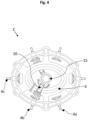
- Figure 4 shows a corresponding bottom view.
- the contact ring unit 2 comprises a ring support structure 3 and a plurality of electrical fixed contacts 4a-4 (n+1) that are coupled to the ring support structure 3.
- the contact ring unit 2 comprises six fixed electrical contacts 4.
- the contact ring unit 2 can comprise more or less than six fixed contacts 4, e.g. two, three, four, five, seven, eight or more fixed contacts 4.
- the contact ring unit 2 further comprises at least one movable contact unit 10 that are coupled to a centrally arranged shaft element 15 which is configured to provide a rotational drive for the movable contact unit 10 around the rotation axis L.
- the movable contact unit 10 is configured to make electrical contact to a respective fixed contact 4 for electrical switching in interaction with the shaft element 15.
- the movable contact unit 10 follow a given guide rail which is formed by a driving cam 6.
- the contact ring unit 2 comprises one movable contact unit 10.
- the ring support structure 3 comprises a non-circular overall shape, in particular an elliptical shape.
- the ring support structure 3 forms an outer surrounding components and substantially defines the shape of the respective contact ring unit 2.
- the driving cam 6 is arranges between the ring support structure 3 and the central shaft element 15 and can also comprise a non-circular overall shape, e.g. an elliptical shape. Due to the non-circular shape of the ring support structure 3 and angularly spaced fixed contacts 4, an improved dielectric distance between chosen adjacent fixed contacts 4 can be achieved.
- the contact ring unit 2 comprises a first extension D1 which is smaller than a second extension D2 along a direction that is substantially perpendicular to a direction of the first extension D1 (see Fig. 3 ). Accordingly, compared to a conventional contact system with circular shape which may comprise a diameter equal to second extension D2 the described contact ring unit 2 can be formed slimmer or narrower in one direction at least and thus enables size reduction in addition to the aforementioned beneficial effect of improved dielectric distance between chosen adjacent fixed contacts 4.
- the ring support structure 3 forms an insulation carrier with the fixed contacts 4a-4(n+1) mounted thereon.
- the central shaft element 15 is configured to initiate rotational switching of the movable contact unit 10.
- Each movable contact unit 10 comprises guide and driving means and further components such as a roller element 11, a carrier element 12, a current collector terminal 13 and telescopic finger elements 14 (see Fig. 2 ).
- the enabled rotational and radial movements of the contact unit 10 are indicated by respective arrows in Fig. 4 .
- the movable contact unit 10 follow the non-circular profile of the driving cam 6 and make a switch from fixed contact 4, e.g. from the contact 4b to the contact 4c (see Figs. 3 and 4 ). Switching even with different distances between the movable contact unit 10 and a respective fixed contact 4 is possible because of the drive and guiding means of the movable contact unit 10 which allow radial translation due to the telescopic guided carrier elements 12 and the finger elements 14.
- the current collector terminal 13 and the fingers set 14 are assembled to the carrier element 12 and are moving together with it. There can be flexible connections or sliding type connections attached to the current collector terminal which takes away the current to a neutral or a next not moving point.
- the movable contact unit 10 is moved for every switching process the same angle.
- an angle between the fixed contact 4b and the fixed contact 4c can be set the same as between the fixed contact 4a and the fixed contact 4b, but the finger elements 14 travel different distances.
- the non-circular shape enables to improve the dielectric distance between the fixed contact 4b and 4c compared to the dielectric distance between the fixed contacts 4a and 4b (see Figs. 3 and 4 ).
- the fixed contacts 4a-4(n+1) are mounted to the insulation ring support structure 3 and not on the insulation bars 16 allows for better dielectric capabilities between the adjacent phases N and N+1 in view of the height distance H which can be measured through transformer oil the tap changer components are immersed in and not measured through insulation surfaces.
Landscapes
- Breakers (AREA)
- Gas-Insulated Switchgears (AREA)
- Rotary Switch, Piano Key Switch, And Lever Switch (AREA)
Abstract
A contact ring unit (2) for a tap changer (1) comprises a ring support structure (3) and a plurality of electrical fixed contacts (4) that are coupled to the ring support structure (3). The contact ring unit (2) further comprises a shaft element (15) that is configured to provide a rotational drive around a rotation axis (L), and at least one movable contact unit (10) that is coupled to the shaft element (15) and that is configured to make electrical contact to a respective fixed contact (4) for electrical switching between two fixed contacts (4) in interaction with the shaft element (15). The ring support structure (3) is configured to hold the fixed contacts (4) in position such that the fixed contacts (4) are arranged along a closed line that comprises a non-circular overall shape.
Description
- The present disclosure is related to a contact ring unit for a tap changer and a corresponding tap changer.
- Tap changers realize a mechanism in transformers which allows for variable turn ratios to be selected in distinct steps, for example. In view of movable and stationary electrically engaging contacts it is a challenge to provide a stable and reliable mechanism with low wear and stress.
- Thus, it is an object to provide a contact unit for a tap changer and a tap changer that each allows for size reduction and a stable and reliable mechanism of interacting components.
- According to an embodiment, a contact ring unit for a tap changer, e.g. an on-load or off-load tap changer, comprises a ring support structure and a plurality of fixed electrical contacts that are coupled to the ring support structure. The ring support structure can form an insulation carrier for the fixed contacts. The contact ring unit further comprises a shaft element that is configured to provide a rotational drive around a rotation axis. The contact ring unit further comprises one or more movable electrical contact units that is coupled to the shaft element and that is configured to make electrical contact to a respective fixed contact for electrical switching between two fixed contacts in interaction with the shaft element. The ring support structure defines a structure which holds the fixed contacts in a respective predetermined position such that the fixed electrical contacts are arranged along a circumferential line that differs from a complete circular overall shape. In other words, the fixed electrical contacts are arranged following a closed formed or virtual path that comprises a non-circular overall shape.
- By use of the described contact ring unit a component for a tap changer is feasible that allows for secure and reliable functioning. The ring support structure may realize a stationary contact system with two or more fixed contacts which are configured to interact with corresponding movable contact units to provide current transfer in a selector of a power diverter switch for the on-load tap changer. Moreover, due to the non-circular overall shape or position specification of the fixed contacts a size reduction of the contact ring, the corresponding tap changer and a corresponding transformer are feasible. The contact ring unit is also suitable to other types of tap changers such as an off-load tap changers.
- Due to the non-circular shape or position specification of the ring support structure and even angularly spaced fixed contacts, an improved dielectric distance between chosen adjacent fixed contacts can be achieved. A corresponding tap changer can comprise a plurality of contact levels each comprising a respective contact ring unit with a non-circular overall shape. The contact ring unit or the ring support structure can comprise an arbitrary shape on each contact level that not follow a complete circular shape. In the following description the ring support structure may be described to comprise a non-circular shape but it can comprise an arbitrary shape such that a position specification of the associated fixed contacts runs along a self-contained line or path that has a non-circular shape.
- The described set up of the contact ring unit further enables to decrease of overall tap changer dimensions and as consequence contributes to decrease of an overall transformer volume which includes one or more tap changers. Due to the non-circular shape of the ring support structure it is further possible to improve dielectric distances between adjacent phases of the tap changer. Each phase can comprise one or more contact ring units that can be arranged one above the other each connected to insulations bars, respectively. Such isolation bars provide support to the ring support structures and the fixed contacts are fixed to a respective ring support structure and not to an insulation bar. The described contact ring unit can be assembled in selectors, pre-selectors such as an on-load tap changer diverter switch type and selector switches or de-energized tap changers providing the aforementioned improvements, respectively.
- According to an embodiment of the contact ring unit, the ring support structure comprises at least one section with a shape that does not follow a circle segment. The ring support structure can comprise one or more sections that follow a circle segment with respect to a top or bottom view along the rotation axis, for example. Between such circle segments there can be a linear, an elliptical or any other shape that differs from a circle segment such that the ring support structure comprises a non-circular overall shape. In particular, the ring support structure can comprises an overall elliptical shape.
- According to a further embodiment of the contact ring unit, the ring support structure comprises a first maximum extension along a first direction and a second maximum extension along a second direction that is perpendicular to the first direction with respect to a plane of extension along the non-circular overall shape, and wherein the second maximum extension is larger than the first maximum extension. Such a configuration may realize an elliptical shape of the ring support structure wherein the first maximum extension would correspond to the minor axis and the second maximum extension would correspond to the major axis of the ellipse.
- It is a recognition of the present disclosure that usual designs for selector mechanisms in tap changers have a circular shape on each contact level. For example, fixed contacts are placed even angularly and dielectric distances between arbitrary two adjacent contacts are the same. When numbering fixed contacts in accordance with regulating electrical scheme, often two adjacent fixed contacts get the first and the last terminal from a regulating winding of a transformer.
- The described contact ring unit in particular takes into account the requirements for dielectric distance between adjacent fixed contacts such that a distance between a first and a last terminal from a regulating winding of a transformer can be set bigger compared to dielectric distance between other adjacent pairs or fixed contacts.
- According to a further embodiment of the contact ring unit, the fixed contacts and the movable contact units are arranged radially with respect to the rotation axis facing towards each other. For example, the ring support structure realizes an outer non-circular component such that the electrical contacts fixed thereon protrude inwards in direction of a center region. The movable electrical contact units protrude outwards in direction towards the ring support structure. The shaft element may be arranged in the center and may realize a central shaft driving and rotating the movable contact units.
- According to a further embodiment of the contact ring unit, a distance between two adjacent fixed contacts along the ring support structure is different than a distance between two other adjacent fixed contacts along the ring support structure. The non-circular ring support structure allows to arrange the fixed contacts non-equidistantly but with the same angle of rotation between adjacent fixed contacts. In particular, the adjacent fixed contacts which include the highest voltage difference should be arranged further apart from each other than the contacts with lower voltage difference.
- According to a further embodiment, the contact ring unit comprises a driving cam that is coupled to the movable contact unit and that is configured to guide a rotational movement of the contact unit around the rotation axis, wherein the driving cam comprises a shape that matches the shape of the ring support structure. Such a driving cam can realize a stable guide rail to enable a secure and reliable rotation and/or proper positioning of the associated movable contact units.
- According to a further embodiment of the contact ring unit, the respective contact units each comprise drive and guiding means and one or more radially movable contact elements with respect to the rotation axis configured to make electrical contact to a respective contact surface of the associated fixed contact. The contact units each can comprise a spring element, a roller element, a bushing element and/or a slider element such that the radially movable contact elements are telescopically extendable and retractable. According to the aforementioned possible embodiments of the contact units a secure and reliable setting of electrical connection is feasible even with different distances between the contacts and contact units. According to the aforementioned possible embodiments of the contact units, a safe and reliable electrical connection can be established even with different distances between the fixed contacts and the rotatable or movable contact units.
- According to an embodiment a tap changer comprises an embodiment of the described contact ring unit. In particular, the tap changer can comprise two different or same embodiments of the described contact ring unit that are coupled to one or more insulation bars such that a given height distance is set between the contact ring units along the direction of the rotational axis. In the case the contact ring units are arranged one above the other, the rotation axis can also be referred to as a longitudinal or vertical axis of the tap changer. As a result of that the tap changer comprises an embodiment of the contact ring unit as described above, features and characteristics of the contact ring unit are also disclosed with respect to the tap changer and vice versa.
- By implementing a non-circular, e.g. elliptical, overall shaped selector or contact ring unit on a respective contact level of the tap changer, it is possible to arrange adjacent fixed contacts further apart from each other than other adjacent contacts which beneficially affects the dielectric characteristics of the tap changer. The fixed contacts can be placed even angularly. On each switching step, a movable contact unit is coupling with a relevant fixed contact, e.g. following a given cam profile, which profile radially control placement of the movable contact units. The movable contact units preferably has the ability to radially move back-and-forth to enable radial or telescopic translation due to guiding elements, e.g. rollers.
- Because of the non-circular shaped contact ring unit, there is potential for reducing of overall dimensions of a tap changer and additionally improved dielectric distances can be achieved between adjacent phases of a tap changer due to designed modular fixed contact ring units. This further allows for improved dielectric distances in a transformer oil which fills a transformer tank and the tap changer assembled therein.
- Exemplary embodiments are explained in the following with the aid of schematic drawings and reference numbers. The figures show:
-
Figures 1-2 an embodiment of a tap changer in different views, -
Figure 3 an embodiment of a contact ring unit for the tap changer in a top view, and -
Figure 4 the embodiment of the contact ring unit according tofigure 3 in a bottom view. - The accompanying figures are included to provide a further understanding. Identical reference numbers designate elements or components with identical functions. In so far as elements or components correspond to one another in terms of their function in different figures, the description thereof is not repeated for each of the following figures. For the sake of clarity elements might not appear with corresponding reference symbols in all figures, possibly.
-
Figure 1 illustrates a side view of atap changer 1 for a transformer which allows for variable turn ratios to be selected in distinct steps, e.g. without a supply interruption during a tap change. For example, the illustrated embodiments can belong to an on-load or off-load tap changer 1 that comprises one or morecontact ring units 2 associated to one or more respective phases N...N+1 configured to enable tap change and power transfer. Thecontact ring units 2 are connected toinsulation bars 16 arranged above each other with respect to a longitudinal axis L of thetap changer 1. The longitudinal axis L also forms a rotation axis of one or more rotatable ormovable contact units 10 of the associatedcontact ring unit 2. Thecontact ring units 2 of the adjacent phase levels N and N+1 are arranged with a given height distance H therebetween which can be affected beneficially in view of a dielectric distance due to the configuration of therespective contact units 2. According to the illustrated embodiment inFig. 1 , thetap changer 1 comprises fourcontact ring units 2a-2d. According to further embodiments, thetap changer 1 can comprise more or lesscontact ring units 2, e.g. two, three, or morecontact ring units 2. This can apply for an off-load tap changer, for example. With respect to an on-load tap changer, the numbers per phase can comprise one, two, three or fourcontact ring units 2, for example. -
Figure 2 shows a perspective view of thetap changer 1 from an oblique bottom view.Figure 3 shows a top view of an embodiment of a respectivecontact ring unit 2.Figure 4 shows a corresponding bottom view. Thecontact ring unit 2 comprises aring support structure 3 and a plurality of electrical fixedcontacts 4a-4 (n+1) that are coupled to thering support structure 3. According to the illustrated embodiment in theFigs. 3 and4 , thecontact ring unit 2 comprises six fixedelectrical contacts 4. According to further embodiments, thecontact ring unit 2 can comprise more or less than six fixedcontacts 4, e.g. two, three, four, five, seven, eight or morefixed contacts 4. - The
contact ring unit 2 further comprises at least onemovable contact unit 10 that are coupled to a centrally arrangedshaft element 15 which is configured to provide a rotational drive for themovable contact unit 10 around the rotation axis L. Themovable contact unit 10 is configured to make electrical contact to a respective fixedcontact 4 for electrical switching in interaction with theshaft element 15. Themovable contact unit 10 follow a given guide rail which is formed by a drivingcam 6. According to the illustrated embodiment in theFigs. 1 to 4 , thecontact ring unit 2 comprises onemovable contact unit 10. - The
ring support structure 3 comprises a non-circular overall shape, in particular an elliptical shape. Thering support structure 3 forms an outer surrounding components and substantially defines the shape of the respectivecontact ring unit 2. The drivingcam 6 is arranges between thering support structure 3 and thecentral shaft element 15 and can also comprise a non-circular overall shape, e.g. an elliptical shape. Due to the non-circular shape of thering support structure 3 and angularly spaced fixedcontacts 4, an improved dielectric distance between chosen adjacent fixedcontacts 4 can be achieved. - In addition, a size reduction of the
contact ring unit 2 and thecorresponding tap changer 1 and the transformer can be achieved. Due to the on-circular shape of thering support structure 3, thecontact ring unit 2 comprises a first extension D1 which is smaller than a second extension D2 along a direction that is substantially perpendicular to a direction of the first extension D1 (seeFig. 3 ). Accordingly, compared to a conventional contact system with circular shape which may comprise a diameter equal to second extension D2 the describedcontact ring unit 2 can be formed slimmer or narrower in one direction at least and thus enables size reduction in addition to the aforementioned beneficial effect of improved dielectric distance between chosen adjacent fixedcontacts 4. - The
ring support structure 3 forms an insulation carrier with the fixedcontacts 4a-4(n+1) mounted thereon. Thecentral shaft element 15 is configured to initiate rotational switching of themovable contact unit 10. Eachmovable contact unit 10 comprises guide and driving means and further components such as aroller element 11, acarrier element 12, acurrent collector terminal 13 and telescopic finger elements 14 (seeFig. 2 ). The enabled rotational and radial movements of thecontact unit 10 are indicated by respective arrows inFig. 4 . - The
movable contact unit 10 follow the non-circular profile of the drivingcam 6 and make a switch fromfixed contact 4, e.g. from thecontact 4b to thecontact 4c (seeFigs. 3 and4 ). Switching even with different distances between themovable contact unit 10 and a respective fixedcontact 4 is possible because of the drive and guiding means of themovable contact unit 10 which allow radial translation due to the telescopic guidedcarrier elements 12 and thefinger elements 14. Thecurrent collector terminal 13 and the fingers set 14 are assembled to thecarrier element 12 and are moving together with it. There can be flexible connections or sliding type connections attached to the current collector terminal which takes away the current to a neutral or a next not moving point. - The
movable contact unit 10 is moved for every switching process the same angle. For example, an angle between thefixed contact 4b and the fixedcontact 4c can be set the same as between thefixed contact 4a and the fixedcontact 4b, but thefinger elements 14 travel different distances. The non-circular shape enables to improve the dielectric distance between thefixed contact contacts Figs. 3 and4 ). Moreover, the fixedcontacts 4a-4(n+1) are mounted to the insulationring support structure 3 and not on the insulation bars 16 allows for better dielectric capabilities between the adjacent phases N and N+1 in view of the height distance H which can be measured through transformer oil the tap changer components are immersed in and not measured through insulation surfaces. - The embodiments shown in the
figures 1 to 4 as stated represent exemplary embodiments of an improvedcontact ring unit 2 and acorresponding tap changer 1; therefore, they do not constitute a complete list of all embodiments according to possible arrangements. Actual arrangements of thecontact ring unit 2 and/or thetap changer 1 may vary from the embodiments shown in the figures. -
- 1
- tap changer / non-circular selector switch
- 2(n)
- respective contact ring unit
- 3
- ring support structure
- 4(n)
- respective fixed contact
- 6
- driving cam
- 10
- respective movable contact unit
- 11
- roller element
- 12
- carrier element
- 13
- current collector terminal
- 14
- finger element
- 15
- central shaft element
- 16
- insulation bar
- D1
- first extension of a contact ring
- D2
- second extension of a contact ring
- H
- height distance between phase levels
- L
- longitudinal axis of the tap changer / rotation axis
Claims (10)
- Contact ring unit (2) for a tap changer (1), comprising:- a ring support structure (3),- a plurality of electrical fixed contacts (4) that are coupled to the ring support structure (3),- a shaft element (15) that is configured to provide a rotational drive around a rotation axis (L), and- a movable contact unit (10) that is coupled to the shaft element (15) and that is configured to make electrical contact to a respective fixed contact (4) for electrical switching between two fixed contacts (4) in interaction with the shaft element (15), wherein the ring support structure (3) is configured to hold the fixed contacts (4) in position such that the fixed contacts (4) are arranged along a closed line that comprises a non-circular overall shape.
- Contact ring unit (2) according to claim 1, wherein the ring support structure (3) forms at least one line section of positioning of the fixed contacts (4) with a shape that does not follow a circle segment.
- Contact ring unit (2) according to any of the preceding claims, wherein the ring support structure (3) forms the closed line of positioning of the fixed contacts (4) that comprises an elliptical shape.
- Contact ring unit (2) according to any of the preceding claims, wherein the ring support structure (3) forms the closed line such that it comprises a first maximum extension (D1) along a first direction and a second maximum extension (D2) along a second direction that is perpendicular to the first direction with respect to a plane of extension along the non-circular overall shape, and wherein the second maximum extension (D2) is larger than the first maximum extension (D1).
- Contact ring unit (2) according to any of the preceding claims, wherein the fixed contacts (4) and the movable contact unit (10) are arranged radially with respect to the rotation axis (L) facing towards each other.
- Contact ring unit (2) according to claim 5, wherein a distance between two adjacent fixed contacts (4) along the ring support structure (3) is different than a distance between two other adjacent fixed contacts (4) along the ring support structure (3).
- Contact ring unit (2) according to any of the preceding claims, comprising:
a driving cam (6) that is coupled to the movable contact unit (10) and that is configured to guide a rotational movement of the contact unit (10) around the rotation axis (L), wherein the driving cam (6) comprises a shape that matches the line predeterminedly formed by the ring support structure (3). - Contact ring unit (2) according to any of the preceding claims, wherein the contact unit (10) comprises drive and guiding means (11, 12) and one or more radially movable contact elements (14) with respect to the rotation axis (L) configured to make electrical contact to a respective contact surface of the associated fixed contact (4).
- Contact unit (10) according to one of the preceding claims, wherein the contact unit (10) comprises a spring element, a roller element, a bushing element and/or a slider element such that the radially movable contact elements (14) are telescopically extendable and retractable.
- A tap changer (1), comprising:- a contact ring unit (2) according to any of the preceding claims,- a further contact ring unit (2) according to any of the preceding claims, and- one or more insulation bars (16) that are coupled to the contact ring units (2) such that a given distance (H) is set between the contact ring units (2) along the direction of the rotational axis (L).
Priority Applications (3)
| Application Number | Priority Date | Filing Date | Title |
|---|---|---|---|
| EP23194510.6A EP4517794A1 (en) | 2023-08-31 | 2023-08-31 | Contact ring unit for a tap changer and tap changer |
| PCT/EP2024/070160 WO2025045437A1 (en) | 2023-08-31 | 2024-07-16 | Contact ring unit for a tap changer and tap changer |
| CN202480055460.6A CN121816634A (en) | 2023-08-31 | 2024-07-16 | Contact ring unit for tap changer and tap changer |
Applications Claiming Priority (1)
| Application Number | Priority Date | Filing Date | Title |
|---|---|---|---|
| EP23194510.6A EP4517794A1 (en) | 2023-08-31 | 2023-08-31 | Contact ring unit for a tap changer and tap changer |
Publications (1)
| Publication Number | Publication Date |
|---|---|
| EP4517794A1 true EP4517794A1 (en) | 2025-03-05 |
Family
ID=87889349
Family Applications (1)
| Application Number | Title | Priority Date | Filing Date |
|---|---|---|---|
| EP23194510.6A Pending EP4517794A1 (en) | 2023-08-31 | 2023-08-31 | Contact ring unit for a tap changer and tap changer |
Country Status (3)
| Country | Link |
|---|---|
| EP (1) | EP4517794A1 (en) |
| CN (1) | CN121816634A (en) |
| WO (1) | WO2025045437A1 (en) |
Citations (2)
| Publication number | Priority date | Publication date | Assignee | Title |
|---|---|---|---|---|
| US3590175A (en) * | 1968-09-14 | 1971-06-29 | Reinhausen Maschf Scheubeck | Composite selector switch and reversing switch for tap-changing regulating transformers |
| DE3832919A1 (en) * | 1988-09-28 | 1990-03-29 | Siemens Ag | LOAD SELECTOR FOR CHANGING THE TRANSLATION RATIO OF THREE-PHASE TRANSFORMERS WITH TRIANGULAR WINDINGS |
-
2023
- 2023-08-31 EP EP23194510.6A patent/EP4517794A1/en active Pending
-
2024
- 2024-07-16 CN CN202480055460.6A patent/CN121816634A/en active Pending
- 2024-07-16 WO PCT/EP2024/070160 patent/WO2025045437A1/en active Pending
Patent Citations (2)
| Publication number | Priority date | Publication date | Assignee | Title |
|---|---|---|---|---|
| US3590175A (en) * | 1968-09-14 | 1971-06-29 | Reinhausen Maschf Scheubeck | Composite selector switch and reversing switch for tap-changing regulating transformers |
| DE3832919A1 (en) * | 1988-09-28 | 1990-03-29 | Siemens Ag | LOAD SELECTOR FOR CHANGING THE TRANSLATION RATIO OF THREE-PHASE TRANSFORMERS WITH TRIANGULAR WINDINGS |
Also Published As
| Publication number | Publication date |
|---|---|
| CN121816634A (en) | 2026-04-07 |
| WO2025045437A1 (en) | 2025-03-06 |
Similar Documents
| Publication | Publication Date | Title |
|---|---|---|
| KR101430542B1 (en) | Switching device | |
| JP4588880B2 (en) | On-load tap changer with selector | |
| CN103503104B (en) | Selector switches assembly for load tap changer | |
| KR101757410B1 (en) | Switching device of moving contacts and fixed contacts of tap selector | |
| KR102642659B1 (en) | Switching systems for on-load tap-changers, on-load tap-changers and methods for switching tap connections in on-load tap-changers | |
| JP7480015B2 (en) | On-load tap changer tap selector | |
| EP4084033B1 (en) | Vacuum interrupter module for a tap changer, power diverter switch, and tap changer | |
| WO2025045437A1 (en) | Contact ring unit for a tap changer and tap changer | |
| EP3171373B1 (en) | On-load tap changing device | |
| KR102642658B1 (en) | Switching systems for on-load tap-changers, on-load tap-changers and methods for switching tap connections in on-load tap-changers | |
| KR102638367B1 (en) | System for controlling vacuum interrupters for power diverter switches, power diverter switches and on-load tap changers | |
| US3366750A (en) | Switching mechanism for tapped regulating transformers | |
| CN114026665B (en) | Multiphase selector-preselector device for on-load tap changers | |
| WO2018148811A1 (en) | Selector with preselector for on-load tap changer | |
| US3194900A (en) | Modular tap-changing selector switch for connecting selectively fixed tap contacts to a transfer switch | |
| KR102328437B1 (en) | Switching device | |
| EP3758035B1 (en) | Single-phase diverter switch for column-type on-load tap changer | |
| US20160351353A1 (en) | Contact Unit For A Tap Changer And A Tap Selector Comprising The Contact Unit | |
| CN202585150U (en) | Switching structure of moving contacts and fixed contacts of tap selector | |
| US3445611A (en) | Selector switch for load tap-changers of regulating transformers | |
| KR20230080503A (en) | Switching systems for on-load tap-changers, switching methods for on-load tap-changers and tap connections in on-load tap-changers | |
| EP4629273A1 (en) | Static contact unit, contact system and tap changer | |
| AU2020381675A1 (en) | Selector for on-load tap changer | |
| EP4651165A1 (en) | Static contact unit, contact system and tap changer | |
| EP4044206B1 (en) | Contact unit and contact system for an on-load tap changer and on-load tap changer |
Legal Events
| Date | Code | Title | Description |
|---|---|---|---|
| PUAI | Public reference made under article 153(3) epc to a published international application that has entered the european phase |
Free format text: ORIGINAL CODE: 0009012 |
|
| STAA | Information on the status of an ep patent application or granted ep patent |
Free format text: STATUS: THE APPLICATION HAS BEEN PUBLISHED |
|
| AK | Designated contracting states |
Kind code of ref document: A1 Designated state(s): AL AT BE BG CH CY CZ DE DK EE ES FI FR GB GR HR HU IE IS IT LI LT LU LV MC ME MK MT NL NO PL PT RO RS SE SI SK SM TR |
|
| STAA | Information on the status of an ep patent application or granted ep patent |
Free format text: STATUS: REQUEST FOR EXAMINATION WAS MADE |
|
| 17P | Request for examination filed |
Effective date: 20250724 |