EP4517739A1 - Data processing method, apparatus, storage medium and vehicle - Google Patents
Data processing method, apparatus, storage medium and vehicle Download PDFInfo
- Publication number
- EP4517739A1 EP4517739A1 EP22941962.7A EP22941962A EP4517739A1 EP 4517739 A1 EP4517739 A1 EP 4517739A1 EP 22941962 A EP22941962 A EP 22941962A EP 4517739 A1 EP4517739 A1 EP 4517739A1
- Authority
- EP
- European Patent Office
- Prior art keywords
- information
- user
- image
- noise reduction
- head
- Prior art date
- Legal status (The legal status is an assumption and is not a legal conclusion. Google has not performed a legal analysis and makes no representation as to the accuracy of the status listed.)
- Pending
Links
Images




Classifications
-
- G—PHYSICS
- G10—MUSICAL INSTRUMENTS; ACOUSTICS
- G10K—SOUND-PRODUCING DEVICES; METHODS OR DEVICES FOR PROTECTING AGAINST, OR FOR DAMPING, NOISE OR OTHER ACOUSTIC WAVES IN GENERAL; ACOUSTICS NOT OTHERWISE PROVIDED FOR
- G10K11/00—Methods or devices for transmitting, conducting or directing sound in general; Methods or devices for protecting against, or for damping, noise or other acoustic waves in general
- G10K11/16—Methods or devices for protecting against, or for damping, noise or other acoustic waves in general
- G10K11/175—Methods or devices for protecting against, or for damping, noise or other acoustic waves in general using interference effects; Masking sound
- G10K11/178—Methods or devices for protecting against, or for damping, noise or other acoustic waves in general using interference effects; Masking sound by electro-acoustically regenerating the original acoustic waves in anti-phase
- G10K11/1781—Methods or devices for protecting against, or for damping, noise or other acoustic waves in general using interference effects; Masking sound by electro-acoustically regenerating the original acoustic waves in anti-phase characterised by the analysis of input or output signals, e.g. frequency range, modes, transfer functions
- G10K11/17821—Methods or devices for protecting against, or for damping, noise or other acoustic waves in general using interference effects; Masking sound by electro-acoustically regenerating the original acoustic waves in anti-phase characterised by the analysis of input or output signals, e.g. frequency range, modes, transfer functions characterised by the analysis of the input signals only
-
- G—PHYSICS
- G10—MUSICAL INSTRUMENTS; ACOUSTICS
- G10K—SOUND-PRODUCING DEVICES; METHODS OR DEVICES FOR PROTECTING AGAINST, OR FOR DAMPING, NOISE OR OTHER ACOUSTIC WAVES IN GENERAL; ACOUSTICS NOT OTHERWISE PROVIDED FOR
- G10K11/00—Methods or devices for transmitting, conducting or directing sound in general; Methods or devices for protecting against, or for damping, noise or other acoustic waves in general
- G10K11/16—Methods or devices for protecting against, or for damping, noise or other acoustic waves in general
- G10K11/175—Methods or devices for protecting against, or for damping, noise or other acoustic waves in general using interference effects; Masking sound
- G10K11/178—Methods or devices for protecting against, or for damping, noise or other acoustic waves in general using interference effects; Masking sound by electro-acoustically regenerating the original acoustic waves in anti-phase
- G10K11/1785—Methods, e.g. algorithms; Devices
- G10K11/17857—Geometric disposition, e.g. placement of microphones
-
- G—PHYSICS
- G10—MUSICAL INSTRUMENTS; ACOUSTICS
- G10K—SOUND-PRODUCING DEVICES; METHODS OR DEVICES FOR PROTECTING AGAINST, OR FOR DAMPING, NOISE OR OTHER ACOUSTIC WAVES IN GENERAL; ACOUSTICS NOT OTHERWISE PROVIDED FOR
- G10K11/00—Methods or devices for transmitting, conducting or directing sound in general; Methods or devices for protecting against, or for damping, noise or other acoustic waves in general
- G10K11/16—Methods or devices for protecting against, or for damping, noise or other acoustic waves in general
- G10K11/175—Methods or devices for protecting against, or for damping, noise or other acoustic waves in general using interference effects; Masking sound
- G10K11/178—Methods or devices for protecting against, or for damping, noise or other acoustic waves in general using interference effects; Masking sound by electro-acoustically regenerating the original acoustic waves in anti-phase
- G10K11/1787—General system configurations
- G10K11/17879—General system configurations using both a reference signal and an error signal
- G10K11/17881—General system configurations using both a reference signal and an error signal the reference signal being an acoustic signal, e.g. recorded with a microphone
-
- G—PHYSICS
- G10—MUSICAL INSTRUMENTS; ACOUSTICS
- G10K—SOUND-PRODUCING DEVICES; METHODS OR DEVICES FOR PROTECTING AGAINST, OR FOR DAMPING, NOISE OR OTHER ACOUSTIC WAVES IN GENERAL; ACOUSTICS NOT OTHERWISE PROVIDED FOR
- G10K11/00—Methods or devices for transmitting, conducting or directing sound in general; Methods or devices for protecting against, or for damping, noise or other acoustic waves in general
- G10K11/16—Methods or devices for protecting against, or for damping, noise or other acoustic waves in general
- G10K11/175—Methods or devices for protecting against, or for damping, noise or other acoustic waves in general using interference effects; Masking sound
- G10K11/178—Methods or devices for protecting against, or for damping, noise or other acoustic waves in general using interference effects; Masking sound by electro-acoustically regenerating the original acoustic waves in anti-phase
- G10K11/1781—Methods or devices for protecting against, or for damping, noise or other acoustic waves in general using interference effects; Masking sound by electro-acoustically regenerating the original acoustic waves in anti-phase characterised by the analysis of input or output signals, e.g. frequency range, modes, transfer functions
- G10K11/17813—Methods or devices for protecting against, or for damping, noise or other acoustic waves in general using interference effects; Masking sound by electro-acoustically regenerating the original acoustic waves in anti-phase characterised by the analysis of input or output signals, e.g. frequency range, modes, transfer functions characterised by the analysis of the acoustic paths, e.g. estimating, calibrating or testing of transfer functions or cross-terms
- G10K11/17817—Methods or devices for protecting against, or for damping, noise or other acoustic waves in general using interference effects; Masking sound by electro-acoustically regenerating the original acoustic waves in anti-phase characterised by the analysis of input or output signals, e.g. frequency range, modes, transfer functions characterised by the analysis of the acoustic paths, e.g. estimating, calibrating or testing of transfer functions or cross-terms between the output signals and the error signals, i.e. secondary path
-
- G—PHYSICS
- G10—MUSICAL INSTRUMENTS; ACOUSTICS
- G10K—SOUND-PRODUCING DEVICES; METHODS OR DEVICES FOR PROTECTING AGAINST, OR FOR DAMPING, NOISE OR OTHER ACOUSTIC WAVES IN GENERAL; ACOUSTICS NOT OTHERWISE PROVIDED FOR
- G10K2210/00—Details of active noise control [ANC] covered by G10K11/178 but not provided for in any of its subgroups
- G10K2210/10—Applications
- G10K2210/128—Vehicles
- G10K2210/1282—Automobiles
-
- G—PHYSICS
- G10—MUSICAL INSTRUMENTS; ACOUSTICS
- G10K—SOUND-PRODUCING DEVICES; METHODS OR DEVICES FOR PROTECTING AGAINST, OR FOR DAMPING, NOISE OR OTHER ACOUSTIC WAVES IN GENERAL; ACOUSTICS NOT OTHERWISE PROVIDED FOR
- G10K2210/00—Details of active noise control [ANC] covered by G10K11/178 but not provided for in any of its subgroups
- G10K2210/30—Means
- G10K2210/301—Computational
- G10K2210/3023—Estimation of noise, e.g. on error signals
- G10K2210/30232—Transfer functions, e.g. impulse response
-
- G—PHYSICS
- G10—MUSICAL INSTRUMENTS; ACOUSTICS
- G10K—SOUND-PRODUCING DEVICES; METHODS OR DEVICES FOR PROTECTING AGAINST, OR FOR DAMPING, NOISE OR OTHER ACOUSTIC WAVES IN GENERAL; ACOUSTICS NOT OTHERWISE PROVIDED FOR
- G10K2210/00—Details of active noise control [ANC] covered by G10K11/178 but not provided for in any of its subgroups
- G10K2210/30—Means
- G10K2210/301—Computational
- G10K2210/3055—Transfer function of the acoustic system
-
- G—PHYSICS
- G10—MUSICAL INSTRUMENTS; ACOUSTICS
- G10K—SOUND-PRODUCING DEVICES; METHODS OR DEVICES FOR PROTECTING AGAINST, OR FOR DAMPING, NOISE OR OTHER ACOUSTIC WAVES IN GENERAL; ACOUSTICS NOT OTHERWISE PROVIDED FOR
- G10K2210/00—Details of active noise control [ANC] covered by G10K11/178 but not provided for in any of its subgroups
- G10K2210/30—Means
- G10K2210/321—Physical
- G10K2210/3221—Headrests, seats or the like, for personal ANC systems
Definitions
- This application relates to the field of artificial intelligence technologies, and in particular, to a data processing method and apparatus, a storage medium, and a vehicle.
- Noise reduction can reduce energy of noise perceived by people, and reduce noise interference to people.
- Current noise reduction methods generally include two methods: passive noise reduction and active noise reduction.
- the passive noise reduction is to reduce vehicle noise in a physical noise reduction manner.
- the active noise reduction generally uses an active noise cancellation (active noise cancellation, ANC) technology.
- An audio signal for suppressing a noise signal is generated by a speaker, and after the noise signal and the noise suppression signal converge and overlap, the noise signal and the noise suppression signal are neutralized to cancel each other out, to finally achieve a purpose of noise reduction.
- a noise reduction effect is usually better at a microphone (which may also be referred to as an error microphone), and a longer distance from the microphone indicates a poorer noise reduction effect.
- a solution to improve an active noise reduction effect is worth studying.
- an embodiment of this application provides a data processing method.
- the method includes: obtaining first image information, where the first image information includes location information of a user; and determining the location information of the user based on the first image information, where the location information of the user is used to determine a sound wave used for noise reduction.
- the image information is obtained to determine the location information of the user, and noise reduction is performed based on the location information of the user, so that a noise reduction effect can be better, and a location of the user can be dynamically determined to reduce noise for the user.
- the location information of the user includes ear location information of the user.
- the location information of the user includes the ear location information of the user, so that the ear location information of the user can be determined by obtaining the image information, and noise reduction can be performed based on the ear location information of the user.
- a noise reduction process is more targeted, and a noise reduction effect is better.
- an ear location of the user can be dynamically determined to reduce noise for the user.
- the location information of the user includes head location information of the user
- the ear location information includes earhole location information
- the determining the location information of the user based on the first image information includes: determining the earhole location information of the user based on the first image information.
- more targeted and more precise noise reduction can be implemented by determining the earhole location information of the user.
- the ear location information may further include information about another location of a left ear and/or a right ear of the user, and may further include information about a location of an area near the left ear and/or the right ear of the user.
- the sound wave used for noise reduction includes a sound wave used for noise reduction in an area corresponding to a location of the user.
- noise reduction is performed on the area corresponding to the location of the user, so that a noise reduction effect can be more targeted.
- the area corresponding to the location of the user includes one or more of the following areas: an area corresponding to a head location of the user, an area corresponding to an ear location of the user, and an area corresponding to an earhole location of the user.
- the area includes an area near a corresponding location, so that a noise reduction area can be adjusted based on a requirement. In this way, a noise reduction process is more flexible, and a noise reduction effect is better.
- the first image information includes two-dimensional information indicating a shape of a face of the user.
- the image information includes the two-dimensional information indicating the shape of the face, so that more precise noise reduction can be implemented based on a personalized user feature.
- the obtaining first image information includes: obtaining the first image information collected by an image sensor, where the image sensor includes one or more of the following: a camera, a depth sensor, and a lidar.
- the camera may be a color camera, a monochrome camera, an infrared camera, or the like.
- image sensor in this embodiment of this application may also be implemented by another sensor, for example, a millimeter-wave radar or an ultrasonic radar.
- manners of obtaining the first image information are diversified, so that hardware can be flexibly deployed based on a requirement. This reduces costs.
- the method further includes: determining head model information, where the head model information includes three-dimensional information indicating a shape of a face in a head model; and the determining the location information of the user based on the first image information includes: determining the ear location information of the user based on an intrinsic parameter of the image sensor, the two-dimensional information, and the three-dimensional information.
- the head model information is determined, and the ear location information of the user is determined based on the three-dimensional information in the head model information, so that an ear location of the user can be determined more precisely and dynamically with movement and turning of a user head, to reduce noise for the user.
- hardware costs are reduced in this process, and an ear location change caused by translation and turning of the user head in an actual scenario can also be estimated.
- the two-dimensional information includes at least three groups of two-dimensional points
- the three-dimensional information includes at least three groups of three-dimensional points corresponding to the at least three groups of two-dimensional points.
- the two-dimensional points may be any three or more groups of two-dimensional points in the first image information, and the three-dimensional points may be three or more groups of three-dimensional points corresponding to the three or more groups of two-dimensional points in the head model information.
- the at least three groups of two-dimensional points and the at least three groups of three-dimensional points corresponding to the at least three groups of two-dimensional points are obtained, so that a noise reduction requirement can be met, and a better noise reduction experience can be provided for a user.
- the head model information includes preset model information.
- noise reduction costs can be reduced based on the preset model information.
- the determining head model information includes: obtaining point cloud data information collected by a depth sensor; and determining the head model information based on the first image information and the point cloud data information.
- the point cloud data information and the first image information is fused to determine the head model information, so that the determined head model information can be closer to actual head information of the user. In this way, an ear location of the user can be more accurately located, to achieve a better noise reduction effect.
- the determining head model information includes: obtaining second image information collected by a camera, where the second image information includes head side location information of the user; and determining the head model information based on the second image information, the preset model information, and an intrinsic parameter of the camera.
- the user cooperates with collecting of the second image information, so that the determined head model information can be closer to actual head information of the user. Therefore, an ear location of the user can be more accurately located, to achieve a better noise reduction effect.
- the head side location information of the user includes the ear location information of the user.
- the ear location information of the user is obtained, so that a finally determined ear location can be more accurate, and a noise reduction effect is better.
- the image sensor includes a first image sensor and a second image sensor
- the determining head model information includes: obtaining third image information collected by the first image sensor and fourth image information collected by the second image sensor; and determining the head model information based on the third image information, the fourth image information, the preset model information, an intrinsic parameter of the first image sensor, an intrinsic parameter of the second image sensor, and an extrinsic parameter between the first image sensor and the second image sensor.
- the third image information and the fourth image information are collected, so that the head model information of the user can be more comprehensively and accurately determined, and the determined head model information is closer to actual head information of the user. In this way, an ear location of the user can be more accurately located, to achieve a better noise reduction effect.
- the method further includes: displaying an area on which noise reduction is performed.
- the area on which noise reduction is performed is displayed, so that the user can learn a current noise reduction status in real time.
- the displaying an area on which noise reduction is performed includes: displaying, based on the first image information, the area on which noise reduction is performed; and/or displaying, based on preset information, the area on which noise reduction is performed.
- the area on which noise reduction is performed is displayed based on the first image information and/or the preset information, so that the user can more accurately learn a current noise reduction status, and a display manner is more vivid.
- an embodiment of this application provides a data processing apparatus.
- the apparatus includes: an obtaining module, configured to obtain first image information, where the first image information includes location information of a user; and a first determining module, configured to determine the location information of the user based on the first image information, where the location information of the user is used to determine a sound wave used for noise reduction.
- the location information of the user includes ear location information of the user.
- the location information of the user includes head location information of the user
- the ear location information includes earhole location information
- the first determining module is configured to determine the earhole location information of the user based on the first image information.
- the sound wave used for noise reduction includes a sound wave used for noise reduction in an area corresponding to a location of the user.
- the area corresponding to the location of the user includes one or more of the following areas: an area corresponding to a head location of the user, an area corresponding to an ear location of the user, and an area corresponding to an earhole location of the user.
- the first image information includes two-dimensional information indicating a shape of a face of the user.
- the obtaining module is configured to obtain the first image information collected by an image sensor, where the image sensor includes one or more of the following: a camera, a depth sensor, or a lidar.
- the apparatus further includes: a second determining module, configured to determine head model information, where the head model information includes three-dimensional information indicating a shape of a face in a head model; and the first determining module is configured to determine the ear location information of the user based on an intrinsic parameter of the image sensor, the two-dimensional information, and the three-dimensional information.
- the two-dimensional information includes at least three groups of two-dimensional points
- the three-dimensional information includes at least three groups of three-dimensional points corresponding to the at least three groups of two-dimensional points.
- the head model information includes preset model information.
- the second determining module is configured to: obtain point cloud data information collected by a depth sensor; and determine the head model information based on the first image information and the point cloud data information.
- the second determining module is configured to: obtain second image information collected by a camera, where the second image information includes head side location information of the user; and determine the head model information based on the second image information, the preset model information, and an intrinsic parameter of the camera.
- the head side location information of the user includes the ear location information of the user.
- the image sensor includes a first image sensor and a second image sensor
- the second determining module is configured to: obtain third image information collected by the first image sensor and fourth image information collected by the second image sensor; and determine the head model information based on the third image information, the fourth image information, the preset model information, an intrinsic parameter of the first image sensor, an intrinsic parameter of the second image sensor, and an extrinsic parameter between the first image sensor and the second image sensor.
- the apparatus further includes: a display module, configured to display an area on which noise reduction is performed.
- the display module is configured to: display, based on the first image information, the area on which noise reduction is performed; and/or display, based on preset information, the area on which noise reduction is performed.
- an embodiment of this application provides a data processing apparatus, including a processor and a memory.
- the memory is configured to store a program.
- the processor is configured to execute the program stored in the memory, so that the apparatus implements one or more data processing methods according to the first aspect or a plurality of possible implementations of the first aspect.
- an embodiment of this application provides a terminal device.
- the terminal device may perform one or more data processing methods according to the first aspect or a plurality of possible implementations of the first aspect.
- an embodiment of this application provides a computer-readable storage medium, where the computer-readable storage medium stores program instructions, and when the program instructions are executed by a computer, the computer is enabled to implement one or more data processing methods according to the first aspect or a plurality of possible implementations of the first aspect.
- an embodiment of this application provides a computer program product, including program instructions.
- the program instructions When the program instructions are executed by a computer, the computer is enabled to implement one or more data processing methods according to the first aspect or a plurality of possible implementations of the first aspect.
- an embodiment of this application provides a vehicle.
- the vehicle includes a processor, and the processor is configured to perform one or more data processing methods according to the first aspect or a plurality of possible implementations of the first aspect.
- example specifically used herein means "used as an example, an embodiment, or an illustration”. Any embodiment illustrated herein as an “example” is not necessarily construed as being superior to or better than other embodiments.
- a noise reduction effect is usually better at a microphone (which may also be referred to as an error microphone), and a longer distance from the microphone indicates a poorer noise reduction effect.
- this application provides a data processing method.
- ear location information of a user can be determined based on image information, so that noise reduction can be performed based on the ear location information.
- an ear location of the user can be accurately determined to perform noise reduction, and noise reduction can be performed for the user by dynamically adjusting the ear location, so that a noise reduction effect is better.
- FIG. 1 is a schematic diagram of an application scenario according to an embodiment of this application.
- the data processing method in embodiments of this application may be used to reduce noise heard by a passenger in a vehicle.
- a data processing system in this embodiment of this application may be disposed on the vehicle, and includes a speaker, a sensor, and a processor.
- the speaker (as shown in (b) in FIG. 1 ) may be configured to emit a sound wave used for noise reduction, to cancel out or partially cancel out noise near an ear location of the passenger. This can reduce noise heard by the passenger in the vehicle.
- a left speaker may be configured to emit a sound wave used to reduce noise near a left ear location of the user, and a right speaker may be configured to emit a sound wave used to reduce noise near a right ear location of the user.
- the sensor may include an image sensor and a microphone.
- the image sensors may include a camera, a depth sensor, a lidar, and the like.
- the camera may be an infrared camera, a color camera, a monochrome camera, or the like.
- the image sensor may be configured to collect earhole location information of the user, for example, may collect an image including a user head through the camera.
- the camera may alternatively be a camera used in a driver monitor system (driver monitor system, DMS) or a camera used in a cockpit monitor system (cockpit monitor system, CMS). This is not limited in this application.
- the microphone (which may be referred to as a mike as shown in (b) in FIG. 1 ) may be disposed near an ear location of a passenger in a vehicle, and is configured to collect a residual signal.
- the microphone may include a capacitive microphone, a dynamic microphone, a laser microphone, or the like.
- the residual signal may be used to indicate residual noise heard by the passenger in the vehicle after a sound wave emitted by the speaker cancels out noise near an ear.
- there may be a plurality of passengers in the vehicle and a plurality of microphones may be disposed for the plurality of passengers to collect corresponding residual signals.
- a plurality of microphones may be disposed for passengers or one passenger.
- a left microphone of a passenger A may be configured to collect residual noise heard by the passenger A in a left ear
- a right microphone of the passenger A may be configured to collect residual noise heard by the passenger A in a right ear.
- the processor may be built in a head unit (or an audio system) on a vehicle as an onboard computing unit.
- the processor is a digital signal processor (digital signal processor, DSP) chip.
- DSP digital signal processor
- the processor may determine ear location information of a user (namely, a passenger in a vehicle) based on image information collected by an image sensor, and determine, based on the information and a residual signal collected by a microphone, a sound wave used for noise reduction.
- the processor may be disposed outside a cloud server. The server and the vehicle may communicate in a wireless connection manner.
- the server and the vehicle may communicate by using a mobile communication technology like a secondgeneration mobile communication technology (2nd-generation, 2G)/a third-generation mobile communication technology (3rd-generation, 3G)/a fourth-generation mobile communication technology (4th-generation, 4G)/a fifth-generation mobile communication technology (5th-generation, 5G) in a wireless communication manner like Wi-Fi, Bluetooth, frequency modulation (frequency modulation, FM), data transmission radio, or satellite communication.
- a mobile communication technology like a secondgeneration mobile communication technology (2nd-generation, 2G)/a third-generation mobile communication technology (3rd-generation, 3G)/a fourth-generation mobile communication technology (4th-generation, 4G)/a fifth-generation mobile communication technology (5th-generation, 5G) in a wireless communication manner like Wi-Fi, Bluetooth, frequency modulation (frequency modulation, FM), data transmission radio, or satellite communication.
- the server may collect information collected by the sensor for calculation, and send a calculation result back to the corresponding vehicle.
- the data processing system may further include a display device (as shown in (a) in FIG. 1 ).
- the display device may include a display, a projection, and the like, and is configured to display an area on which noise reduction is performed.
- the data processing method in embodiments of this application may also be used in another scenario in which noise reduction needs to be performed other than the vehicle-mounted scenario shown in FIG. 1 . This is not limited in this application.
- FIG. 2 to FIG. 6 uses FIG. 2 to FIG. 6 as examples to describe in detail the data processing method in embodiments of this application based on the foregoing data processing system.
- FIG. 2 is a flowchart of a data processing method according to an embodiment of this application. The method may be used in the foregoing data processing system. As shown in FIG. 2 , the method may include the following steps.
- Step S201 Obtain first image information.
- the first image information may include one frame of image collected by the image sensor, or may be a plurality of frames of images.
- the plurality of frames of images may be a plurality of consecutive frames of images, or may be a plurality of inconsecutive frames of images.
- the first image information may be an image collected by the image sensor, or may be information obtained based on an image collected by the image sensor.
- the image sensor includes one or more of the following: a camera, a depth sensor, and a lidar.
- the camera may include an infrared camera and a color camera.
- the first image information includes location information of a user, and the location information of the user may be determined based on one or more frames of images collected by the image sensor.
- the location information of the user may include head location information of the user.
- the head location information may include a head location in a camera coordinate system, and the camera coordinate system may indicate a coordinate system that uses a focus center of the image sensor (for example, a camera) as an origin.
- the first image information may include a frame of two-dimensional image collected by a single camera.
- the two-dimensional image may include an image of a part or all of a head of the user.
- the head included in the image may also be the head seen from a side.
- the image includes an image of a head in a side-deflection posture.
- Ahead detection algorithm head detector can be used to detect the head in the image to determine the head location information.
- the first image information may include two-dimensional information indicating a shape of a face of the user.
- the two-dimensional information may include a two-dimensional key point of a head image of the user, and may indicate a location of a key area of the face of the user, for example, a plane location of an area like eyebrows, eyes, a nose, a mouth, and a face contour.
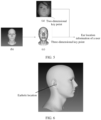
- FIG. 3 is a schematic diagram of determining the two-dimensional key point according to an embodiment of this application.
- the first image information refer to (a) in FIG. 3 .
- the image corresponding to the detected head namely, the foregoing head image
- refer to (b) in FIG. 3 According to the head image, two-dimensional key points in the head image may be determined by using a face key point detection method.
- the face key point detection method may be a method based on cascaded pose regression (cascaded pose regression, CPR), a method based on an active appearance model (Active Appearance Model, AAM), a method based on a constrained local model (Constrained Local Model, CLM), a face key point detection method based on deep learning, or the like. This is not limited in this application.
- the two-dimensional key point may be a key point in a camera coordinate system.
- Step S202 Determine ear location information of the user based on the first image information.
- the ear location information is used to determine a sound wave used for noise reduction.
- the ear location information of the user may be ear location information of a left ear and/or a right ear of the user in a world coordinate system.
- the ear location information of the user may include, for example, coordinates of any location of the left ear and/or the right ear of the user, or may include coordinates of a location of an area near the left ear and/or the right ear of the user. This is not limited in this application.
- the ear location information of the user (which may be the ear location information of the user in the world coordinate system) may be determined based on the location information of the user included in the first image information, to perform noise reduction. For example, after the ear location information of the user is determined, a transfer function from an ear location of the user to a microphone may be determined (for example, may be obtained from a pre-established transfer function library, where the transfer function library may include transfer functions between different locations in a vehicle and a microphone).
- a control signal for noise reduction is determined by using a filter based on the transfer function, and a residual signal and a noise signal (which may be referred to as a noise signal) collected by the microphone.
- a speaker is enabled to emit a corresponding reverse sound wave based on the control signal to cancel out noise, to achieve a noise reduction effect.
- the image information is obtained to determine the ear location information of the user, and noise reduction is performed based on the ear location information of the user, so that a noise reduction process is more targeted, and a noise reduction effect is better.
- the ear location of the user can be dynamically determined to reduce noise for the user.
- the ear location information may include earhole location information.
- Step S202 includes: determining the earhole location information of the user based on the first image information.
- the earhole location information of the user may include, for example, coordinates of a vertex location of a left and/or a right earhole of the user in a world coordinate system, or may include coordinates of locations such as a central point location and a lowest point location of a left and/or a right earhole of the user. This is not limited in this application.
- the sound wave used for noise reduction may include a sound wave used for noise reduction in an area corresponding to a location of the user.
- noise reduction is performed on the area corresponding to the location of the user, so that a noise reduction effect can be more targeted.
- the area corresponding to the location of the user includes one or more of the following areas: an area corresponding to a head location of the user, an area corresponding to an ear location of the user, and an area corresponding to an earhole location of the user.
- the area corresponding to the location of the user may further include an area other than the foregoing areas. This is not limited in this application.
- the area may include an area near a corresponding location.
- the area corresponding to the head location of the user may include an area in which a head of the user is located and an area near the head
- the area corresponding to the ear location of the user may include an area in which an ear of the user is located and an area near the ear.
- the area includes the area near a corresponding location, so that the noise reduction area can be adjusted based on a requirement. In this way, a noise reduction process is more flexible, and a noise reduction effect is better.
- FIG. 4 is a flowchart of a data processing method according to an embodiment of this application. As shown in FIG. 4 , the method further includes the following steps.
- Step S401 Determine head model information.
- the head model information includes three-dimensional information indicating a shape of a face in a head model.
- the head model may be a three-dimensional model.
- the three-dimensional information may include a three-dimensional key point in the head model in a head coordinate system.
- the head coordinate system may use a central point of a connection line between two ears as an origin, or may use another location on a head of the user or another location outside a head of the user as an origin. This is not limited in this application.
- the three-dimensional key point may correspond to the two-dimensional key point, and indicates a three-dimensional location in the head coordinate system.
- FIG. 5 is a schematic diagram of determining ear location information according to an embodiment of this application.
- the three-dimensional key point may correspond to the two-dimensional key point.
- a corresponding three-dimensional key point (as shown in (c) in FIG. 5 ) may be determined in a determined head model (as shown in (b) in FIG. 5 ) based on the two-dimensional key point.
- the ear location information of a user in a world coordinate system may be determined based on two-dimensional key points in a head image and three-dimensional key points in the head model.
- a preset head model may be used to determine the head model information. For details, refer to the following.
- the head model information may include preset model information.
- the model may be formed by a plurality of vertices and a plurality of triangular facets, and a quantity of vertices and a quantity of triangular facets may be preset.
- point cloud data information may be collected and fused with the first image information, to determine personalized head model information more precisely. For details, refer to the following.
- step S401 includes:
- the first image information may include a two-dimensional image collected by a camera, for example, a high-resolution grayscale image collected by an infrared camera.
- Data fusion may be performed on the two-dimensional point cloud image and the grayscale image to obtain a high-resolution point cloud image, that is, each pixel of the grayscale image carries corresponding depth information in the point cloud image.
- a manner of performing the data fusion may be an image alignment (image alignment) manner. This is not limited in this application.
- a head of the user may be further detected in an image based on the high-resolution point cloud image by using a head detection algorithm, and face reconstruction is performed on an image corresponding to the head in the point cloud image by using a regression network, to obtain parameters (which may include parameters indicating a shape (shape) and a size (scale) of the head) of a head model.
- the head model may be a three-dimensional morphable model (3d morphable model, 3DMM). In this way, the head model information can be determined.
- the point cloud data information and the first image information is fused to determine the head model information, so that the determined head model information can be closer to actual head information of the user. In this way, an ear location of the user can be more accurately located, to achieve a better noise reduction effect.
- the user may cooperate with collecting of second image information, to more precisely determine personalized head model information. For details, refer to the following.
- step S401 includes:
- a head side may be detected in the image by using a head detection algorithm, and two-dimensional key points indicating a shape of a face corresponding to the head side are determined by using a face key point detection method in the image corresponding to the head side.
- the preset model information may be, for example, the foregoing preset head model information, and three-dimensional key points in the head model are determined based on the foregoing method.
- Head posture information of the user is determined based on the two-dimensional key points in the head side image, the three-dimensional key points in the head model, and the intrinsic parameter of the camera (namely, a camera that collects the second image information).
- the head posture information may include a rotation matrix R and a translation vector T that indicate a head posture of the user.
- a manner of determining the head posture information of the user may use a perspective-n-point (perspective-n-point, PnP) algorithm, an efficient perspective-n-point (efficient perspective-n-point, EPnP) algorithm, or the like.
- the three-dimensional key points in the head model are indicated as a linear combination of four non-coplanar control points, and coordinates of the four control points in a camera coordinate system are solved based on the two-dimensional key points in the head side image and the intrinsic parameter of the camera, to obtain coordinates of all the three-dimensional key points in the camera coordinate system. Therefore, the head posture information of the user is determined.
- the head posture information may indicate a relationship of conversion between a head coordinate system and the camera coordinate system.
- the head posture information of the user may also be determined in another manner other than the PnP algorithm. This is not limited in this application.
- three-dimensional coordinate points of a corresponding earhole (or an ear) in the three-dimensional key points in the head model may be determined.
- Two-dimensional coordinate points of the three-dimensional coordinate points of the corresponding earhole in the image of the head side are determined through projection based on the intrinsic parameter of the camera and the head posture information.
- the three-dimensional coordinate points are compared with the two-dimensional coordinate points of the corresponding earhole (or the ear) in the image of the head side, and parameters (which may include parameters such as a shape and a size) of the head model (the model may be a 3DMM) is optimized in a loss optimization manner (for example, a gradient descent algorithm), to obtain optimized parameters of the head model, to determine the head model information.
- parameters which may include parameters such as a shape and a size
- the head model may be a 3DMM
- a loss optimization manner for example, a gradient descent algorithm
- the user cooperates with collecting of the second image information, so that the determined head model information can be closer to actual head information of the user. Therefore, an ear location of the user can be more accurately located, to achieve a better noise reduction effect.
- personalized head model information may be more precisely determined based on image information respectively collected by the two types of cameras. For details, refer to the following.
- An image sensor may include a first image sensor and a second image sensor.
- Step S301 includes:
- the extrinsic parameter between the first image sensor and the second image sensor may indicate a relationship of geometric conversion between a camera coordinate system corresponding to the first image sensor and a camera coordinate system corresponding to the second image sensor.
- a head may be detected from an image in the third image information by using a head detection algorithm, and two-dimensional key points indicating a shape of a face of the user (which may be referred to as first two-dimensional key points) may be determined by using a face key point detection method from the image corresponding to the head.
- a head may be detected from an image in the fourth image information by using a head detection algorithm, and two-dimensional key points indicating a shape of a face of the user (which may be referred to as second two-dimensional key points) may be determined by using a face key point detection method from the image corresponding to the head.
- the preset model information may be, for example, the foregoing preset head model information, and three-dimensional key points in the head model are determined based on the foregoing method.
- Head posture information of the user corresponding to the third image information may be determined by using the foregoing PnP algorithm based on the first two-dimensional key points, the three-dimensional key points in the head model, and the intrinsic parameter of the first image sensor.
- the head posture information may include a rotation matrix R and a translation vector T that indicate a head posture of the user.
- Three-dimensional coordinate points (which may be referred to as first three-dimensional coordinate points) corresponding to an earhole (or an ear) in a camera coordinate system corresponding to the first image sensor are determined based on the head posture information and three-dimensional coordinate points corresponding to the earhole (or the ear) in the head coordinate system in the head model.
- head posture information of the user corresponding to the fourth image information may be determined by using the foregoing PnP algorithm based on the second two-dimensional key points, the three-dimensional key points in the head model, and the intrinsic parameter of the second image sensor.
- Three-dimensional coordinate points (which may be referred to as second three-dimensional coordinate points) corresponding to an earhole (or an ear) in a camera coordinate system corresponding to the second image sensor are determined based on the head posture information and the three-dimensional coordinate points corresponding to the earhole (or the ear) in the head coordinate system in the head model.
- the first three-dimensional coordinate points may be converted into three-dimensional coordinate points in the camera coordinate system corresponding to the second image sensor based on the relationship of geometric conversion between the camera coordinate system corresponding to the first image sensor and the camera coordinate system corresponding to the second image sensor, and the three-dimensional coordinate points are compared with the second three-dimensional coordinate points. For example, a mean squared error between the two three-dimensional coordinate points is determined as a loss function.
- Parameters (which may include parameters such as a shape and a size) of the head model (the model may be a 3DMM) is optimized in a loss optimization manner (for example, a gradient descent algorithm), to obtain optimized parameters of the head model, to determine the head model information.
- the second three-dimensional coordinate points may also be converted into three-dimensional coordinate points in a camera coordinate system corresponding to a third image sensor, and the three-dimensional coordinate points are compared with the first three-dimensional coordinate points, to optimize parameters of the head model. This is not limited in this application.
- the head model information may be determined in a manner other than the foregoing four methods. This is not limited in this application.
- the third image information and the fourth image information are collected, so that the head model information of the user can be more comprehensively and accurately determined, and the determined head model information is closer to actual head information of the user. In this way, an ear location of the user can be more accurately located, to achieve a better noise reduction effect.
- Step S202 further includes: Step S402: Determine the ear location information of the user based on the intrinsic parameter of the image sensor, two-dimensional information, and the three-dimensional information.
- the three-dimensional information may be determined in the head model information based on two-dimensional key points in the two-dimensional information.
- Head posture information of the user corresponding to the first image information may be determined by using the foregoing PnP algorithm based on the two-dimensional key points in the two-dimensional information, the three-dimensional key points in the three-dimensional information, and the intrinsic parameter of the image sensor (namely, an image sensor that collects the first image information).
- the head posture information may include a rotation matrix R and a translation vector T that indicate a head posture of the user.
- the head posture information may indicate a relationship of conversion between a head coordinate system and a camera coordinate system
- ear location information that is, three-dimensional coordinates corresponding to ears in the head model
- the ear location information in the head coordinate system is converted into ear location information in the camera coordinate system corresponding to the image sensor based on the head posture information. Therefore, the ear location information in the camera coordinate system may be converted into ear location information in a world coordinate system based on the extrinsic parameter of the image sensor, to perform noise reduction accordingly.
- FIG. 6 is a schematic diagram of an earhole location in a head model according to an embodiment of this application. A location indicated by a point in FIG. 6 is an earhole location of a right ear in the head model.
- the head model information is determined, and the ear location information of the user is determined based on the three-dimensional information in the head model information, so that an ear location of the user can be determined more precisely and dynamically with movement and turning of a user head, to reduce noise for the user.
- hardware costs are reduced in this process, and an ear location change caused by translation and turning of the user head in an actual scenario can also be estimated.
- the two-dimensional information may include at least three groups of two-dimensional points, and the three-dimensional information may include at least three groups of three-dimensional points corresponding to the at least three groups of two-dimensional points.
- the two-dimensional points may be any three or more groups of two-dimensional points in the first image information, for example, may be any three groups of two-dimensional key points in the head image.
- the three-dimensional points may be more than three groups of three-dimensional points corresponding to the three or more groups of two-dimensional points in the head model information, for example, may be more than three groups of three-dimensional key points corresponding to the three or more groups of two-dimensional key points in the head model.
- the at least three groups of two-dimensional points and the at least three groups of three-dimensional points corresponding to the at least three groups of two-dimensional points are obtained, so that a noise reduction requirement can be met, and a better noise reduction experience can be provided for a user.
- the method may further include the following step.
- Step S203 Display an area on which noise reduction is performed.
- the area on which noise reduction is performed may be displayed in a form of a text, an image, a video, or the like. This is not limited in this application. An area on which noise reduction is currently performed may be displayed on a display device.
- the area on which noise reduction is performed is displayed, so that the user can learn a current noise reduction status in real time.
- That the area on which noise reduction is performed is displayed may include:
- an area indicating the ear location of the user in the first image information may be identified (for example, shown by using a block), and an identified image is displayed on a display device.
- a text indicating a noise reduction area may be displayed on a display device. For example, "The current noise reduction area is locations of ears of a driver" is displayed on the display device.
- the user may be notified of the noise reduction area in another manner, for example, through audio broadcasting. This is not limited in this application.
- an embodiment of this application further provides a data processing apparatus.
- the data processing apparatus is configured to perform the technical solutions described in the foregoing method embodiments. For example, the steps of the data processing methods shown in FIG. 2 to FIG. 6 may be performed.
- FIG. 7 is a diagram of a structure of a data processing apparatus according to an embodiment of this application. As shown in FIG. 7 , the apparatus includes:
- the image information is obtained to determine the ear location information of the user, and noise reduction is performed based on the ear location information of the user, so that a noise reduction process is more targeted, and a noise reduction effect is better.
- an ear location of the user can be dynamically determined to reduce noise for the user.
- the location information of the user may include head location information of the user, and the ear location information includes earhole location information.
- the first determining module 702 is configured to determine the earhole location information of the user based on the first image information.
- more targeted and more precise noise reduction can be implemented by determining the earhole location information of the user.
- the sound wave used for noise reduction may include a sound wave used for noise reduction in an area corresponding to a location of the user.
- noise reduction is performed on the area corresponding to the location of the user, so that a noise reduction effect can be more targeted.
- the area corresponding to the location of the user may include one or more of the following areas: an area corresponding to a head location of the user, an area corresponding to an ear location of the user, and an area corresponding to an earhole location of the user.
- the area includes an area near a corresponding location, so that a noise reduction area can be adjusted based on a requirement. In this way, a noise reduction process is more flexible, and a noise reduction effect is better.
- the first image information may include two-dimensional information indicating a shape of a face of the user.
- the image information includes the two-dimensional information indicating the shape of the face, so that more precise noise reduction can be implemented based on a personalized user feature.
- the obtaining module 701 may be configured to obtain the first image information collected by an image sensor, where the image sensor includes one or more of the following: a camera, a depth sensor, and a lidar.
- manners of obtaining the first image information are diversified, so that hardware can be flexibly deployed based on a requirement. This reduces costs.
- the apparatus may further include: a second determining module, configured to determine head model information, where the head model information includes three-dimensional information indicating a shape of a face in a head model; and the first determining module is configured to determine the ear location information of the user based on an intrinsic parameter of the image sensor, the two-dimensional information, and the three-dimensional information.
- a second determining module configured to determine head model information, where the head model information includes three-dimensional information indicating a shape of a face in a head model
- the first determining module is configured to determine the ear location information of the user based on an intrinsic parameter of the image sensor, the two-dimensional information, and the three-dimensional information.
- the head model information is determined, and the ear location information of the user is determined based on the three-dimensional information in the head model information, so that an ear location of the user can be determined more precisely and dynamically with movement and turning of a user head, to reduce noise for the user.
- hardware costs are reduced in this process, and an ear location change caused by translation and turning of the user head in an actual scenario can also be estimated.
- the two-dimensional information may include at least three groups of two-dimensional points
- the three-dimensional information may include at least three groups of three-dimensional points corresponding to the at least three groups of two-dimensional points.
- the at least three groups of two-dimensional points and the at least three groups of three-dimensional points corresponding to the at least three groups of two-dimensional points are obtained, so that a noise reduction requirement can be met, and a better noise reduction experience can be provided for a user.
- the head model information may include preset model information.
- noise reduction costs can be reduced based on the preset model information.
- the second determining module may be configured to: obtain point cloud data information collected by a depth sensor; and determine the head model information based on the first image information and the point cloud data information.
- the point cloud data information and the first image information is fused to determine the head model information, so that the determined head model information can be closer to actual head information of the user. In this way, an ear location of the user can be more accurately located, to achieve a better noise reduction effect.
- the user cooperates with collecting of the second image information, so that the determined head model information can be closer to actual head information of the user. Therefore, an ear location of the user can be more accurately located, to achieve a better noise reduction effect.
- the head side location information of the user includes the ear location information of the user.
- the ear location information of the user is obtained, so that a finally determined ear location can be more accurate, and a noise reduction effect is better.
- the image sensor may include a first image sensor and a second image sensor.
- the second determining module may be configured to: obtain third image information collected by the first image sensor and fourth image information collected by the second image sensor; and determine the head model information based on the third image information, the fourth image information, the preset model information, an intrinsic parameter of the first image sensor, an intrinsic parameter of the second image sensor, and an extrinsic parameter between the first image sensor and the second image sensor.
- the third image information and the fourth image information are collected, so that the head model information of the user can be more comprehensively and accurately determined, and the determined head model information is closer to actual head information of the user. In this way, an ear location of the user can be more accurately located, to achieve a better noise reduction effect.
- the apparatus may further include a display module, configured to display an area on which noise reduction is performed.
- the area on which noise reduction is performed is displayed, so that the user can learn a current noise reduction status in real time.
- the display module may be further configured to: display, based on the first image information, the area on which noise reduction is performed; and/or display, based on preset information, the area on which noise reduction is performed.
- the area on which noise reduction is performed is displayed based on the first image information and/or the preset information, so that the user can more accurately learn a current noise reduction status, and a display manner is more vivid.
- FIG. 8 is a diagram of a structure of an electronic device according to an embodiment of this application.
- an electronic device 800 may be a terminal, for example, a vehicle or a head unit, or may be a chip built in a terminal, and may implement the steps of the data processing methods shown in FIG. 2 to FIG. 6 , or implement functions of the modules of the data processing apparatus shown in FIG. 7 .
- the electronic device 800 includes a processor 801 and an interface circuit 802 coupled to the processor. It should be understood that although only one processor and one interface circuit are shown in FIG. 8 , the electronic device 800 may include another quantity of processors and interface circuits.
- the interface circuit 802 is configured to connect to another component of the terminal, for example, a memory or another processor.
- the processor 801 is configured to perform signal interaction with another component through the interface circuit 802.
- the interface circuit 802 may be an input/output interface of the processor 801.
- the processor 801 reads, through the interface circuit 802, a computer program or instructions in a memory coupled to the processor 801, and decodes and executes the computer program or instructions.
- the electronic device 800 may be enabled to implement the solutions in the data processing methods provided in embodiments of this application.
- these programs or instructions are stored in a memory outside the electronic device 800.
- the memory temporarily stores some or all content of the foregoing programs or instructions.
- these programs or instructions are stored in a memory inside the electronic device 800.
- the electronic device 800 may be disposed in the terminal in this embodiment of this application.
- some content of the programs or instructions is stored in a memory outside the electronic device 800, and other content of the programs or instructions is stored in a memory inside the electronic device 800.
- FIG. 9 is a diagram of a structure of an electronic device according to an embodiment of this application.
- the electronic device may be a vehicle or a head unit, or may be a chip built in a terminal, and implements the steps of the data processing methods shown in FIG. 2 to FIG. 6 , or implements functions of the modules of the the data processing apparatus shown in FIG. 7 .
- an electronic device 900 includes a processor 901, and a memory 902 coupled to the processor. It should be understood that although only one processor and one memory are shown in FIG. 9 , the electronic device 900 may include another quantity of processors and memories.
- the memory 902 is configured to store a computer program or computer instructions. When these computer programs or instructions are executed by the processor 901, the electronic device 900 may be enabled to implement the steps in the data processing methods in embodiments of this application.
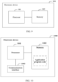
- FIG. 10 is a diagram of a structure of an electronic device according to an embodiment of this application.
- an electronic device 1000 may be the foregoing terminal, for example, a vehicle or a head unit, or may be a chip built in a terminal, and may perform the data processing methods shown in any one of FIG. 2 to FIG. 6 .
- the electronic device 1000 includes at least one processor 1801, at least one memory 1802, and at least one communication interface 1803.
- the electronic device may further include a general-purpose component like an antenna. Details are not described herein again.
- the processor 1801 may be a general-purpose central processing unit (CPU), a microprocessor, an application-specific integrated circuit (application-specific integrated circuit, ASIC), or one or more integrated circuits configured to control program execution in the foregoing solutions.
- the processor 1801 may include one or more processing units.
- the processor 1801 may include an application processor (application processor, AP), a modem processor, a graphics processing unit (graphics processing unit, GPU), an image signal processor (image signal processor, ISP), a controller, a video codec, a digital signal processor (digital signal processor, DSP), a baseband processor, and/or a neural-network processing unit (neural-network processing unit, NPU).
- Different processing units may be separate components, or may be integrated into one or more processors.
- the memory 1802 may be a read-only memory (read-only memory, ROM) or another type of static storage device that can store static information and instructions, a random access memory (random access memory, RAM) or another type of dynamic storage device that can store information and instructions, or may be an electrically erasable programmable read-only memory (Electrically Erasable Programmable Read-Only Memory, EEPROM), a compact disc read-only memory (Compact Disc Read-Only Memory, CD-ROM) or another compact disc storage, an optical disc storage (including a compact disc, a laser disc, an optical disc, a digital versatile disc, a Blu-ray disc, and the like), a magnetic disk storage medium or another magnetic storage device, or any other medium that can be configured to carry or store expected program code in a form of an instruction or a data structure and that can be accessed by a computer.
- the memory may exist independently, and is connected to the processor through a bus. Alternatively, the memory and the processor may be integrated.
- the memory 1802 is configured to store application program code for executing the foregoing solutions, and the processor 1801 controls the execution.
- the processor 1801 is configured to execute the application program code stored in the memory 1802.
- the obtaining module 701 in FIG. 7 may be implemented by the communication interface 1803 in FIG. 8
- the first determining module 702 in FIG. 7 may be implemented by the processor 1801 in FIG. 8 .
- FIG. 11 is a diagram of a structure of an electronic device according to an embodiment of this application.
- the electronic device 1100 may be the foregoing terminal, for example, a vehicle or a head unit, or may be a chip built in a terminal, and may perform the data processing methods shown in any one of FIG. 2 to FIG. 6 .
- the electronic device 1100 includes a sensor 1101 and a processing unit 1102 coupled to the sensor 1101. It should be understood that although only one sensor and one processing unit are shown in FIG. 11 , the electronic device 1100 may include another quantity of sensors and processors.
- the electronic device may further include a display unit 1103.
- the display unit may be coupled to the processing unit 1102, and is configured to display a noise reduction area after the processing unit 1102 determines the noise reduction area, so that a visualization effect of the noise reduction area can be achieved, and user experience is better.
- the electronic device in this embodiment of this application may be implemented by software, for example, by the foregoing computer program or instructions.
- a corresponding computer program or corresponding instructions may be stored in a memory inside a terminal, and the foregoing function is implemented by reading the corresponding computer program or corresponding instructions inside the memory through a processor.
- the electronic device in this embodiment of this application may be implemented by hardware.
- the processing unit 1102 is a processor.
- the computer-readable storage medium may be a tangible device that may maintain and store instructions used by an instruction execution device.
- the computer-readable storage medium may be, for example, but is not limited to an electronic storage device, a magnetic storage device, an optical storage device, an electromagnetic storage device, a semiconductor storage device, or any suitable combination thereof.
- the computer-readable storage medium includes: a portable computer disk, a hard disk, a random access memory (Random Access Memory, RAM), a read-only memory (Read-Only Memory, ROM), an erasable programmable read-only memory (Erasable PROM, EPROM), a static random access memory (Static Random Access Memory, SRAM), a portable compact disc read-only memory (Compact Disc Read-Only Memory, CD-ROM), a digital video disc (Digital Video Disc, DVD), a memory stick, a floppy disk, a mechanical coding device, for example, a punched card or a protrusion structure in a groove that stores instructions, and any suitable combination of the foregoing devices.
- Computer-readable program instructions or code described herein can be downloaded to respective computing/processing devices from the computer-readable storage medium, or downloaded to an external computer or external storage device via a network, for example, the Internet, a local area network, a wide area network and/or a wireless network.
- the network may include copper transmission cables, optical fiber transmission, wireless transmission, routers, firewalls, switches, gateway computers, and/or edge servers.
- a network adapter card or a network interface in each computing/processing device receives the computer-readable program instructions from the network, and forwards the computer-readable program instructions for storage in a computer-readable storage medium in each computing/processing device.
- the computer program instructions used to perform the operations in this application may be assembly instructions, instruction set architecture (Instruction Set Architecture, ISA) instructions, machine instructions, machine-related instructions, microcode, firmware instructions, status setting data, or source code or object code written in any combination of one or more programming languages.
- the programming languages include an obj ect-oriented programming language like Smalltalk or C++, and a conventional procedural programming language like a "C" language or a similar programming language.
- the computer-readable program instructions may be entirely executed on a user computer, partially executed on a user computer, executed as an independent software package, partially executed on a user computer while partially executed on a remote computer, or entirely executed on a remote computer or a server.
- These computer-readable program instructions may be provided to a processor of a general-purpose computer, a dedicated computer, or another programmable data processing apparatus to produce a machine, so that when the instructions are executed by a processor of a computer or another programmable data processing apparatus, an apparatus for implementing functions/acts specified in one or more blocks in the flowcharts and/or block diagrams is produced.
- These computer-readable program instructions may also be stored in the computer-readable storage medium. These instructions enable a computer, a programmable data processing apparatus, and/or another device to work in a specific manner. Therefore, the computer-readable medium storing the instructions includes an artifact that includes instructions for implementing various aspects of the functions/acts specified in the one or more blocks in the flowcharts and/or the block diagrams.
- each block in the flowcharts or block diagrams may indicate a module, a program segment, or a part of the instructions, and the module, the program segment, or the part of the instructions includes one or more executable instructions for implementing a specified logical function.
- a function marked in the block may also occur in a sequence different from that marked in the accompanying drawings. For example, two consecutive blocks may actually be executed substantially in parallel, and may sometimes be executed in a reverse order, depending on a function involved.
- each block in the block diagrams and/or the flowcharts, and a combination of blocks in the block diagrams and/or the flowcharts may be implemented by hardware (for example, a circuit or an ASIC (Application-Specific Integrated Circuit, application-specific integrated circuit)) that performs a corresponding function or action, or may be implemented by a combination of hardware and software, for example, firmware.
- hardware for example, a circuit or an ASIC (Application-Specific Integrated Circuit, application-specific integrated circuit)
- firmware for example, firmware
Landscapes
- Physics & Mathematics (AREA)
- Engineering & Computer Science (AREA)
- Acoustics & Sound (AREA)
- Multimedia (AREA)
- Image Processing (AREA)
Abstract
Description
- This application relates to the field of artificial intelligence technologies, and in particular, to a data processing method and apparatus, a storage medium, and a vehicle.
- Noise reduction can reduce energy of noise perceived by people, and reduce noise interference to people. Current noise reduction methods generally include two methods: passive noise reduction and active noise reduction. The passive noise reduction is to reduce vehicle noise in a physical noise reduction manner. The active noise reduction generally uses an active noise cancellation (active noise cancellation, ANC) technology. An audio signal for suppressing a noise signal is generated by a speaker, and after the noise signal and the noise suppression signal converge and overlap, the noise signal and the noise suppression signal are neutralized to cancel each other out, to finally achieve a purpose of noise reduction.
- In the active noise reduction method, a noise reduction effect is usually better at a microphone (which may also be referred to as an error microphone), and a longer distance from the microphone indicates a poorer noise reduction effect. A solution to improve an active noise reduction effect is worth studying.
- In view of this, a data processing method and apparatus, a storage medium, and a vehicle are proposed, to improve a noise reduction effect and user experience.
- According to a first aspect, an embodiment of this application provides a data processing method. The method includes: obtaining first image information, where the first image information includes location information of a user; and determining the location information of the user based on the first image information, where the location information of the user is used to determine a sound wave used for noise reduction.
- According to this embodiment of this application, the image information is obtained to determine the location information of the user, and noise reduction is performed based on the location information of the user, so that a noise reduction effect can be better, and a location of the user can be dynamically determined to reduce noise for the user.
- According to the first aspect, in a first possible implementation of the data processing method, the location information of the user includes ear location information of the user.
- According to this embodiment of this application, the location information of the user includes the ear location information of the user, so that the ear location information of the user can be determined by obtaining the image information, and noise reduction can be performed based on the ear location information of the user. In this way, a noise reduction process is more targeted, and a noise reduction effect is better. In addition, by tracking the ear location information of the user, an ear location of the user can be dynamically determined to reduce noise for the user.
- According to the first aspect or the first possible implementation of the first aspect, in a second possible implementation of the data processing method, the location information of the user includes head location information of the user, the ear location information includes earhole location information, and the determining the location information of the user based on the first image information includes: determining the earhole location information of the user based on the first image information.
- According to this embodiment of this application, more targeted and more precise noise reduction can be implemented by determining the earhole location information of the user.
- It should be understood that, in this embodiment of this application, in addition to the earhole location information, the ear location information may further include information about another location of a left ear and/or a right ear of the user, and may further include information about a location of an area near the left ear and/or the right ear of the user.
- According to the first aspect or the first or second possible implementation of the first aspect, in a third possible implementation of the data processing method, the sound wave used for noise reduction includes a sound wave used for noise reduction in an area corresponding to a location of the user.
- According to this embodiment of this application, noise reduction is performed on the area corresponding to the location of the user, so that a noise reduction effect can be more targeted.
- According to the third possible implementation of the first aspect, in a fourth possible implementation of the data processing method, the area corresponding to the location of the user includes one or more of the following areas: an area corresponding to a head location of the user, an area corresponding to an ear location of the user, and an area corresponding to an earhole location of the user.
- According to this embodiment of this application, the area includes an area near a corresponding location, so that a noise reduction area can be adjusted based on a requirement. In this way, a noise reduction process is more flexible, and a noise reduction effect is better.
- According to the first aspect or the first or the second or the third or the fourth possible implementation of the first aspect, in a fifth possible implementation of the data processing method, the first image information includes two-dimensional information indicating a shape of a face of the user.
- According to this embodiment of this application, the image information includes the two-dimensional information indicating the shape of the face, so that more precise noise reduction can be implemented based on a personalized user feature.
- According to the first aspect or the first or second or third or fourth or fifth possible implementation of the first aspect, in a sixth possible implementation of the data processing method, the obtaining first image information includes: obtaining the first image information collected by an image sensor, where the image sensor includes one or more of the following: a camera, a depth sensor, and a lidar.
- The camera may be a color camera, a monochrome camera, an infrared camera, or the like.
- It should be understood that the image sensor in this embodiment of this application may also be implemented by another sensor, for example, a millimeter-wave radar or an ultrasonic radar.
- According to this embodiment of this application, manners of obtaining the first image information are diversified, so that hardware can be flexibly deployed based on a requirement. This reduces costs.
- According to the fifth or the sixth possible implementation of the first aspect, in a seventh possible implementation of the data processing method, the method further includes: determining head model information, where the head model information includes three-dimensional information indicating a shape of a face in a head model; and the determining the location information of the user based on the first image information includes: determining the ear location information of the user based on an intrinsic parameter of the image sensor, the two-dimensional information, and the three-dimensional information.
- According to this embodiment of this application, the head model information is determined, and the ear location information of the user is determined based on the three-dimensional information in the head model information, so that an ear location of the user can be determined more precisely and dynamically with movement and turning of a user head, to reduce noise for the user. In addition, hardware costs are reduced in this process, and an ear location change caused by translation and turning of the user head in an actual scenario can also be estimated.
- According to the fifth, the sixth, or the seventh possible implementation of the first aspect, in an eighth possible implementation of the data processing method, the two-dimensional information includes at least three groups of two-dimensional points, and the three-dimensional information includes at least three groups of three-dimensional points corresponding to the at least three groups of two-dimensional points.
- The two-dimensional points may be any three or more groups of two-dimensional points in the first image information, and the three-dimensional points may be three or more groups of three-dimensional points corresponding to the three or more groups of two-dimensional points in the head model information.
- According to this embodiment of this application, the at least three groups of two-dimensional points and the at least three groups of three-dimensional points corresponding to the at least three groups of two-dimensional points are obtained, so that a noise reduction requirement can be met, and a better noise reduction experience can be provided for a user.
- According to the seventh or the eighth possible implementation of the first aspect, in a ninth possible implementation of the data processing method, the head model information includes preset model information.
- According to this embodiment of this application, noise reduction costs can be reduced based on the preset model information.
- According to the seventh, the eighth, or the ninth possible implementation of the first aspect, in a tenth possible implementation of the data processing method, the determining head model information includes: obtaining point cloud data information collected by a depth sensor; and determining the head model information based on the first image information and the point cloud data information.
- According to this embodiment of this application, the point cloud data information and the first image information is fused to determine the head model information, so that the determined head model information can be closer to actual head information of the user. In this way, an ear location of the user can be more accurately located, to achieve a better noise reduction effect.
- According to the seventh, the eighth, the ninth, or the tenth possible implementation of the first aspect, in an eleventh possible implementation of the data processing method, the determining head model information includes: obtaining second image information collected by a camera, where the second image information includes head side location information of the user; and determining the head model information based on the second image information, the preset model information, and an intrinsic parameter of the camera.
- According to this embodiment of this application, the user cooperates with collecting of the second image information, so that the determined head model information can be closer to actual head information of the user. Therefore, an ear location of the user can be more accurately located, to achieve a better noise reduction effect.
- According to the eleventh possible implementation of the first aspect, in a twelfth possible implementation of the data processing method, the head side location information of the user includes the ear location information of the user.
- According to this embodiment of this application, the ear location information of the user is obtained, so that a finally determined ear location can be more accurate, and a noise reduction effect is better.
- According to the seventh, eighth, ninth, tenth, eleventh, or twelfth possible implementation of the first aspect, in a thirteenth possible implementation of the data processing method, the image sensor includes a first image sensor and a second image sensor, and the determining head model information includes: obtaining third image information collected by the first image sensor and fourth image information collected by the second image sensor; and determining the head model information based on the third image information, the fourth image information, the preset model information, an intrinsic parameter of the first image sensor, an intrinsic parameter of the second image sensor, and an extrinsic parameter between the first image sensor and the second image sensor.
- According to this embodiment of this application, the third image information and the fourth image information are collected, so that the head model information of the user can be more comprehensively and accurately determined, and the determined head model information is closer to actual head information of the user. In this way, an ear location of the user can be more accurately located, to achieve a better noise reduction effect.
- According to the first aspect or the first or second or third or fourth or fifth or sixth or seventh or eighth or ninth or tenth or eleventh or twelfth or thirteenth possible implementation of the first aspect, in a fourteenth possible implementation of the data processing method, the method further includes: displaying an area on which noise reduction is performed.
- According to this embodiment of this application, the area on which noise reduction is performed is displayed, so that the user can learn a current noise reduction status in real time.
- According to the fourteenth possible implementation of the first aspect, in a fifteenth possible implementation of the data processing method, the displaying an area on which noise reduction is performed includes: displaying, based on the first image information, the area on which noise reduction is performed; and/or displaying, based on preset information, the area on which noise reduction is performed.
- According to this embodiment of this application, the area on which noise reduction is performed is displayed based on the first image information and/or the preset information, so that the user can more accurately learn a current noise reduction status, and a display manner is more vivid.
- According to a second aspect, an embodiment of this application provides a data processing apparatus. The apparatus includes: an obtaining module, configured to obtain first image information, where the first image information includes location information of a user; and a first determining module, configured to determine the location information of the user based on the first image information, where the location information of the user is used to determine a sound wave used for noise reduction.
- According to the second aspect, in a first possible implementation of the data processing apparatus, the location information of the user includes ear location information of the user.
- According to the second aspect or the first possible implementation of the second aspect, in a second possible implementation of the data processing apparatus, the location information of the user includes head location information of the user, the ear location information includes earhole location information, and the first determining module is configured to determine the earhole location information of the user based on the first image information.
- According to the second aspect or the first or second possible implementation of the second aspect, in a third possible implementation of the data processing apparatus, the sound wave used for noise reduction includes a sound wave used for noise reduction in an area corresponding to a location of the user.
- According to the third possible implementation of the second aspect, in a fourth possible implementation of the data processing apparatus, the area corresponding to the location of the user includes one or more of the following areas: an area corresponding to a head location of the user, an area corresponding to an ear location of the user, and an area corresponding to an earhole location of the user.
- According to the second aspect or the first or the second or the third or the fourth possible implementation of the second aspect, in a fifth possible implementation of the data processing apparatus, the first image information includes two-dimensional information indicating a shape of a face of the user.
- According to the second aspect or the first or the second or the third or the fourth or the fifth possible implementation of the second aspect, in a sixth possible implementation of the data processing apparatus, the obtaining module is configured to obtain the first image information collected by an image sensor, where the image sensor includes one or more of the following: a camera, a depth sensor, or a lidar.
- According to the fifth or the sixth possible implementation of the second aspect, in a seventh possible implementation of the data processing apparatus, the apparatus further includes: a second determining module, configured to determine head model information, where the head model information includes three-dimensional information indicating a shape of a face in a head model; and the first determining module is configured to determine the ear location information of the user based on an intrinsic parameter of the image sensor, the two-dimensional information, and the three-dimensional information.
- According to the fifth, the sixth, or the seventh possible implementation of the second aspect, in an eighth possible implementation of the data processing apparatus, the two-dimensional information includes at least three groups of two-dimensional points, and the three-dimensional information includes at least three groups of three-dimensional points corresponding to the at least three groups of two-dimensional points.
- According to the seventh or the eighth possible implementation of the second aspect, in a ninth possible implementation of the data processing apparatus, the head model information includes preset model information.
- According to the seventh, the eighth, or the ninth possible implementation of the second aspect, in a tenth possible implementation of the data processing apparatus, the second determining module is configured to: obtain point cloud data information collected by a depth sensor; and determine the head model information based on the first image information and the point cloud data information.
- According to the seventh, the eighth, the ninth, or the tenth possible implementation of the second aspect, in an eleventh possible implementation of the data processing apparatus, the second determining module is configured to: obtain second image information collected by a camera, where the second image information includes head side location information of the user; and determine the head model information based on the second image information, the preset model information, and an intrinsic parameter of the camera.
- According to the eleventh possible implementation of the second aspect, in a twelfth possible implementation of the data processing apparatus, the head side location information of the user includes the ear location information of the user.
- According to the seventh, eighth, ninth, tenth, eleventh, or twelfth possible implementation of the second aspect, in a thirteenth possible implementation of the data processing apparatus, the image sensor includes a first image sensor and a second image sensor, and the second determining module is configured to: obtain third image information collected by the first image sensor and fourth image information collected by the second image sensor; and determine the head model information based on the third image information, the fourth image information, the preset model information, an intrinsic parameter of the first image sensor, an intrinsic parameter of the second image sensor, and an extrinsic parameter between the first image sensor and the second image sensor.
- According to the second aspect or the first or second or third or fourth or fifth or sixth or seventh or eighth or ninth or tenth or eleventh or twelfth or thirteenth possible implementation of the second aspect, in a fourteenth possible implementation of the data processing apparatus, the apparatus further includes: a display module, configured to display an area on which noise reduction is performed.
- According to the fourteenth possible implementation of the second aspect, in a fifteenth possible implementation of the data processing apparatus, the display module is configured to: display, based on the first image information, the area on which noise reduction is performed; and/or display, based on preset information, the area on which noise reduction is performed.
- According to a third aspect, an embodiment of this application provides a data processing apparatus, including a processor and a memory. The memory is configured to store a program. The processor is configured to execute the program stored in the memory, so that the apparatus implements one or more data processing methods according to the first aspect or a plurality of possible implementations of the first aspect.
- According to a fourth aspect, an embodiment of this application provides a terminal device. The terminal device may perform one or more data processing methods according to the first aspect or a plurality of possible implementations of the first aspect.
- According to a fifth aspect, an embodiment of this application provides a computer-readable storage medium, where the computer-readable storage medium stores program instructions, and when the program instructions are executed by a computer, the computer is enabled to implement one or more data processing methods according to the first aspect or a plurality of possible implementations of the first aspect.
- According to a sixth aspect, an embodiment of this application provides a computer program product, including program instructions. When the program instructions are executed by a computer, the computer is enabled to implement one or more data processing methods according to the first aspect or a plurality of possible implementations of the first aspect.
- According to a seventh aspect, an embodiment of this application provides a vehicle. The vehicle includes a processor, and the processor is configured to perform one or more data processing methods according to the first aspect or a plurality of possible implementations of the first aspect.
- These and other aspects of this application are more concise and easy to understand in descriptions of the following (a plurality of) embodiments.
- The accompanying drawings included in the specification and constituting a part of the specification together with the specification show example embodiments, features, and aspects of this application, and are used to explain principles of this application.
-
FIG. 1 is a schematic diagram of an application scenario according to an embodiment of this application; -
FIG. 2 is a flowchart of a data processing method according to an embodiment of this application; -
FIG. 3 is a schematic diagram of determining a two-dimensional key point according to an embodiment of this application; -
FIG. 4 is a flowchart of a data processing method according to an embodiment of this application; -
FIG. 5 is a schematic diagram of determining ear location information according to an embodiment of this application; -
FIG. 6 is a schematic diagram of an earhole location in a head model according to an embodiment of this application; -
FIG. 7 is a diagram of a structure of a data processing apparatus according to an embodiment of this application; -
FIG. 8 is a diagram of a structure of an electronic device according to an embodiment of this application; -
FIG. 9 is a diagram of a structure of an electronic device according to an embodiment of this application; -
FIG. 10 is a diagram of a structure of an electronic device according to an embodiment of this application; and -
FIG. 11 is a diagram of a structure of an electronic device according to an embodiment of this application. - The following describes in detail various example embodiments, features, and aspects of this application with reference to the accompanying drawings. Same reference numerals in the accompanying drawings indicate elements with same or similar functions. Although various aspects of embodiments are shown in the accompanying drawings, the accompanying drawings do not need to be drawn to scale unless otherwise noted.
- The term "example" specifically used herein means "used as an example, an embodiment, or an illustration". Any embodiment illustrated herein as an "example" is not necessarily construed as being superior to or better than other embodiments.
- In addition, to better describe this application, the following specific implementations provide many specific details. A person skilled in the art should understand that this application may also be implemented without some specific details. In some examples, methods, means, elements, and circuits that are well known by a person skilled in the art are not described in detail, to highlight a main purpose of this application.
- In an active noise reduction method, a noise reduction effect is usually better at a microphone (which may also be referred to as an error microphone), and a longer distance from the microphone indicates a poorer noise reduction effect.
- To resolve the foregoing technical problem, this application provides a data processing method. According to the data processing method in embodiments of this application, ear location information of a user can be determined based on image information, so that noise reduction can be performed based on the ear location information. According to the method in embodiments of this application, an ear location of the user can be accurately determined to perform noise reduction, and noise reduction can be performed for the user by dynamically adjusting the ear location, so that a noise reduction effect is better.
-
FIG. 1 is a schematic diagram of an application scenario according to an embodiment of this application. As shown inFIG. 1 , in a possible application scenario, the data processing method in embodiments of this application may be used to reduce noise heard by a passenger in a vehicle. A data processing system in this embodiment of this application may be disposed on the vehicle, and includes a speaker, a sensor, and a processor. - The speaker (as shown in (b) in
FIG. 1 ) may be configured to emit a sound wave used for noise reduction, to cancel out or partially cancel out noise near an ear location of the passenger. This can reduce noise heard by the passenger in the vehicle. There may be one or more speakers. A left speaker may be configured to emit a sound wave used to reduce noise near a left ear location of the user, and a right speaker may be configured to emit a sound wave used to reduce noise near a right ear location of the user. - The sensor may include an image sensor and a microphone.
- There may be one or more image sensors (as shown in (a) in
FIG. 1 ), and the image sensors may include a camera, a depth sensor, a lidar, and the like. The camera may be an infrared camera, a color camera, a monochrome camera, or the like. The image sensor may be configured to collect earhole location information of the user, for example, may collect an image including a user head through the camera. In a vehicle-mounted scenario, the camera may alternatively be a camera used in a driver monitor system (driver monitor system, DMS) or a camera used in a cockpit monitor system (cockpit monitor system, CMS). This is not limited in this application. - The microphone (which may be referred to as a mike as shown in (b) in
FIG. 1 ) may be disposed near an ear location of a passenger in a vehicle, and is configured to collect a residual signal. The microphone may include a capacitive microphone, a dynamic microphone, a laser microphone, or the like. The residual signal may be used to indicate residual noise heard by the passenger in the vehicle after a sound wave emitted by the speaker cancels out noise near an ear. For example, there may be a plurality of passengers in the vehicle, and a plurality of microphones may be disposed for the plurality of passengers to collect corresponding residual signals. A plurality of microphones may be disposed for passengers or one passenger. For example, a left microphone of a passenger A may be configured to collect residual noise heard by the passenger A in a left ear, and a right microphone of the passenger A may be configured to collect residual noise heard by the passenger A in a right ear. - The processor may be built in a head unit (or an audio system) on a vehicle as an onboard computing unit. For example, the processor is a digital signal processor (digital signal processor, DSP) chip. The processor may determine ear location information of a user (namely, a passenger in a vehicle) based on image information collected by an image sensor, and determine, based on the information and a residual signal collected by a microphone, a sound wave used for noise reduction. Alternatively, the processor may be disposed outside a cloud server. The server and the vehicle may communicate in a wireless connection manner. For example, the server and the vehicle may communicate by using a mobile communication technology like a secondgeneration mobile communication technology (2nd-generation, 2G)/a third-generation mobile communication technology (3rd-generation, 3G)/a fourth-generation mobile communication technology (4th-generation, 4G)/a fifth-generation mobile communication technology (5th-generation, 5G) in a wireless communication manner like Wi-Fi, Bluetooth, frequency modulation (frequency modulation, FM), data transmission radio, or satellite communication. Through the communication between the vehicle and the server, the server may collect information collected by the sensor for calculation, and send a calculation result back to the corresponding vehicle.
- Optionally, the data processing system may further include a display device (as shown in (a) in
FIG. 1 ). The display device may include a display, a projection, and the like, and is configured to display an area on which noise reduction is performed. - It should be noted that the data processing method in embodiments of this application may also be used in another scenario in which noise reduction needs to be performed other than the vehicle-mounted scenario shown in
FIG. 1 . This is not limited in this application. - The following uses
FIG. 2 to FIG. 6 as examples to describe in detail the data processing method in embodiments of this application based on the foregoing data processing system. -
FIG. 2 is a flowchart of a data processing method according to an embodiment of this application. The method may be used in the foregoing data processing system. As shown inFIG. 2 , the method may include the following steps. - Step S201: Obtain first image information.
- The first image information may include one frame of image collected by the image sensor, or may be a plurality of frames of images. The plurality of frames of images may be a plurality of consecutive frames of images, or may be a plurality of inconsecutive frames of images. The first image information may be an image collected by the image sensor, or may be information obtained based on an image collected by the image sensor. The image sensor includes one or more of the following: a camera, a depth sensor, and a lidar. The camera may include an infrared camera and a color camera.
- The first image information includes location information of a user, and the location information of the user may be determined based on one or more frames of images collected by the image sensor. The location information of the user may include head location information of the user.
- The head location information may include a head location in a camera coordinate system, and the camera coordinate system may indicate a coordinate system that uses a focus center of the image sensor (for example, a camera) as an origin. For example, the first image information may include a frame of two-dimensional image collected by a single camera. The two-dimensional image may include an image of a part or all of a head of the user. The head included in the image may also be the head seen from a side. For example, the image includes an image of a head in a side-deflection posture. Ahead detection algorithm (head detector) can be used to detect the head in the image to determine the head location information.
- The first image information may include two-dimensional information indicating a shape of a face of the user.
- The two-dimensional information may include a two-dimensional key point of a head image of the user, and may indicate a location of a key area of the face of the user, for example, a plane location of an area like eyebrows, eyes, a nose, a mouth, and a face contour.
FIG. 3 is a schematic diagram of determining the two-dimensional key point according to an embodiment of this application. For example, for the first image information, refer to (a) inFIG. 3 . For the image corresponding to the detected head (namely, the foregoing head image), refer to (b) inFIG. 3 . According to the head image, two-dimensional key points in the head image may be determined by using a face key point detection method. For the two-dimensional key points, refer to points indicated in (c) inFIG. 3 . The face key point detection method may be a method based on cascaded pose regression (cascaded pose regression, CPR), a method based on an active appearance model (Active Appearance Model, AAM), a method based on a constrained local model (Constrained Local Model, CLM), a face key point detection method based on deep learning, or the like. This is not limited in this application. The two-dimensional key point may be a key point in a camera coordinate system. - Step S202: Determine ear location information of the user based on the first image information.
- The ear location information is used to determine a sound wave used for noise reduction. The ear location information of the user may be ear location information of a left ear and/or a right ear of the user in a world coordinate system. The ear location information of the user may include, for example, coordinates of any location of the left ear and/or the right ear of the user, or may include coordinates of a location of an area near the left ear and/or the right ear of the user. This is not limited in this application.
- The ear location information of the user (which may be the ear location information of the user in the world coordinate system) may be determined based on the location information of the user included in the first image information, to perform noise reduction. For example, after the ear location information of the user is determined, a transfer function from an ear location of the user to a microphone may be determined (for example, may be obtained from a pre-established transfer function library, where the transfer function library may include transfer functions between different locations in a vehicle and a microphone). By using an active noise reduction method, a control signal for noise reduction is determined by using a filter based on the transfer function, and a residual signal and a noise signal (which may be referred to as a noise signal) collected by the microphone. A speaker is enabled to emit a corresponding reverse sound wave based on the control signal to cancel out noise, to achieve a noise reduction effect.
- According to this embodiment of this application, the image information is obtained to determine the ear location information of the user, and noise reduction is performed based on the ear location information of the user, so that a noise reduction process is more targeted, and a noise reduction effect is better. In addition, by tracking the ear location information of the user, the ear location of the user can be dynamically determined to reduce noise for the user.
- To determine a noise reduction area more precisely, the ear location information may include earhole location information. Step S202 includes: determining the earhole location information of the user based on the first image information.
- The earhole location information of the user may include, for example, coordinates of a vertex location of a left and/or a right earhole of the user in a world coordinate system, or may include coordinates of locations such as a central point location and a lowest point location of a left and/or a right earhole of the user. This is not limited in this application.
- Therefore, more targeted and more precise noise reduction can be implemented.
- The sound wave used for noise reduction may include a sound wave used for noise reduction in an area corresponding to a location of the user.
- According to this embodiment of this application, noise reduction is performed on the area corresponding to the location of the user, so that a noise reduction effect can be more targeted.
- The area corresponding to the location of the user includes one or more of the following areas: an area corresponding to a head location of the user, an area corresponding to an ear location of the user, and an area corresponding to an earhole location of the user. The area corresponding to the location of the user may further include an area other than the foregoing areas. This is not limited in this application.
- The area may include an area near a corresponding location. For example, the area corresponding to the head location of the user may include an area in which a head of the user is located and an area near the head, and the area corresponding to the ear location of the user may include an area in which an ear of the user is located and an area near the ear.
- According to this embodiment of this application, the area includes the area near a corresponding location, so that the noise reduction area can be adjusted based on a requirement. In this way, a noise reduction process is more flexible, and a noise reduction effect is better.
- The following describes in detail, by using
FIG. 4 , a method for determining the ear location information based on the first image information in this application.FIG. 4 is a flowchart of a data processing method according to an embodiment of this application. As shown inFIG. 4 , the method further includes the following steps. - Step S401: Determine head model information.
- The head model information includes three-dimensional information indicating a shape of a face in a head model. The head model may be a three-dimensional model. The three-dimensional information may include a three-dimensional key point in the head model in a head coordinate system. The head coordinate system may use a central point of a connection line between two ears as an origin, or may use another location on a head of the user or another location outside a head of the user as an origin. This is not limited in this application. The three-dimensional key point may correspond to the two-dimensional key point, and indicates a three-dimensional location in the head coordinate system.
-
FIG. 5 is a schematic diagram of determining ear location information according to an embodiment of this application. The three-dimensional key point may correspond to the two-dimensional key point. After the two-dimensional key point (as shown in (a) inFIG. 5 ) is determined, a corresponding three-dimensional key point (as shown in (c) inFIG. 5 ) may be determined in a determined head model (as shown in (b) inFIG. 5 ) based on the two-dimensional key point. As shown inFIG. 5 , the ear location information of a user in a world coordinate system may be determined based on two-dimensional key points in a head image and three-dimensional key points in the head model. - The following describes in detail four methods for determining the head model information.
- If the user cannot cooperate with a system to collect the head model information, a preset head model may be used to determine the head model information. For details, refer to the following.
- For example, the head model information may include preset model information.
- The model may be formed by a plurality of vertices and a plurality of triangular facets, and a quantity of vertices and a quantity of triangular facets may be preset.
- Therefore, noise reduction costs can be reduced.
- If a depth sensor is further deployed in a data processing system, point cloud data information may be collected and fused with the first image information, to determine personalized head model information more precisely. For details, refer to the following.
- For example, step S401 includes:
- obtaining the point cloud data information collected by the depth sensor, where
- the point cloud data information may include a two-dimensional point cloud image (which may be of low resolution) collected by the depth sensor; and
- determining the head model information based on the first image information and the point cloud data information.
- The first image information may include a two-dimensional image collected by a camera, for example, a high-resolution grayscale image collected by an infrared camera.
- Data fusion may be performed on the two-dimensional point cloud image and the grayscale image to obtain a high-resolution point cloud image, that is, each pixel of the grayscale image carries corresponding depth information in the point cloud image. A manner of performing the data fusion may be an image alignment (image alignment) manner. This is not limited in this application. A head of the user may be further detected in an image based on the high-resolution point cloud image by using a head detection algorithm, and face reconstruction is performed on an image corresponding to the head in the point cloud image by using a regression network, to obtain parameters (which may include parameters indicating a shape (shape) and a size (scale) of the head) of a head model. The head model may be a three-dimensional morphable model (3d morphable model, 3DMM). In this way, the head model information can be determined.
- According to this embodiment of this application, the point cloud data information and the first image information is fused to determine the head model information, so that the determined head model information can be closer to actual head information of the user. In this way, an ear location of the user can be more accurately located, to achieve a better noise reduction effect.
- If only a camera is deployed in the data processing system, the user may cooperate with collecting of second image information, to more precisely determine personalized head model information. For details, refer to the following.
- For example, step S401 includes:
- obtaining the second image information collected by the camera, where
- the second image information includes head side location information of the user, the second image information may include an image captured by a single camera, and the image may be one or more frames of images, the user may be prompted, by a vehicle-mounted display device, a speaker, or the like, to cooperate with rotating of a head, to obtain a head side image of the user, where the side may be, for example, a posture in which the head of the user turns at an angle of 45° to an angle of 60°, and
- the head side location information of the user may include the ear location information of the user, to more precisely locate a location of an ear of the user, that is, the head side image may include all or a part of an ear image of the user; and
- determining the head model information based on the second image information, the preset model information, and an intrinsic parameter of the camera.
- For the image included in the second image information, a head side may be detected in the image by using a head detection algorithm, and two-dimensional key points indicating a shape of a face corresponding to the head side are determined by using a face key point detection method in the image corresponding to the head side. The preset model information may be, for example, the foregoing preset head model information, and three-dimensional key points in the head model are determined based on the foregoing method. Head posture information of the user is determined based on the two-dimensional key points in the head side image, the three-dimensional key points in the head model, and the intrinsic parameter of the camera (namely, a camera that collects the second image information). The head posture information may include a rotation matrix R and a translation vector T that indicate a head posture of the user. For example, a manner of determining the head posture information of the user may use a perspective-n-point (perspective-n-point, PnP) algorithm, an efficient perspective-n-point (efficient perspective-n-point, EPnP) algorithm, or the like. The three-dimensional key points in the head model are indicated as a linear combination of four non-coplanar control points, and coordinates of the four control points in a camera coordinate system are solved based on the two-dimensional key points in the head side image and the intrinsic parameter of the camera, to obtain coordinates of all the three-dimensional key points in the camera coordinate system. Therefore, the head posture information of the user is determined. The head posture information may indicate a relationship of conversion between a head coordinate system and the camera coordinate system. The head posture information of the user may also be determined in another manner other than the PnP algorithm. This is not limited in this application.
- After the head posture information of the user is determined, three-dimensional coordinate points of a corresponding earhole (or an ear) in the three-dimensional key points in the head model may be determined. Two-dimensional coordinate points of the three-dimensional coordinate points of the corresponding earhole in the image of the head side are determined through projection based on the intrinsic parameter of the camera and the head posture information. The three-dimensional coordinate points are compared with the two-dimensional coordinate points of the corresponding earhole (or the ear) in the image of the head side, and parameters (which may include parameters such as a shape and a size) of the head model (the model may be a 3DMM) is optimized in a loss optimization manner (for example, a gradient descent algorithm), to obtain optimized parameters of the head model, to determine the head model information.
- According to this embodiment of this application, the user cooperates with collecting of the second image information, so that the determined head model information can be closer to actual head information of the user. Therefore, an ear location of the user can be more accurately located, to achieve a better noise reduction effect.
- In a vehicle-mounted scenario, if cameras that are respectively used in a driver monitor system DMS and a cockpit monitor system CMS are deployed in a vehicle, personalized head model information may be more precisely determined based on image information respectively collected by the two types of cameras. For details, refer to the following.
- An image sensor may include a first image sensor and a second image sensor. Step S301 includes:
- obtaining third image information collected by the first image sensor and fourth image information collected by the second image sensor, where
- the first image sensor may be a camera used in the DMS, the second image sensor may be a camera used in the CMS, the third image information may include a frame of two-dimensional image collected by the camera used in the DMS, and the fourth image information may include a frame of two-dimensional image collected by the camera used in the CMS; and it should be understood that the first image sensor and the second image sensor in this embodiment of this application may also be implemented by another vehicle-mounted camera, or may be implemented by a depth sensor, a lidar, or the like; and
- determining the head model information based on the third image information, the fourth image information, the preset model information, an intrinsic parameter of the first image sensor, an intrinsic parameter of the second image sensor, and an extrinsic parameter between the first image sensor and the second image sensor.
- The extrinsic parameter between the first image sensor and the second image sensor may indicate a relationship of geometric conversion between a camera coordinate system corresponding to the first image sensor and a camera coordinate system corresponding to the second image sensor.
- A head may be detected from an image in the third image information by using a head detection algorithm, and two-dimensional key points indicating a shape of a face of the user (which may be referred to as first two-dimensional key points) may be determined by using a face key point detection method from the image corresponding to the head. Similarly, a head may be detected from an image in the fourth image information by using a head detection algorithm, and two-dimensional key points indicating a shape of a face of the user (which may be referred to as second two-dimensional key points) may be determined by using a face key point detection method from the image corresponding to the head. The preset model information may be, for example, the foregoing preset head model information, and three-dimensional key points in the head model are determined based on the foregoing method.
- Head posture information of the user corresponding to the third image information may be determined by using the foregoing PnP algorithm based on the first two-dimensional key points, the three-dimensional key points in the head model, and the intrinsic parameter of the first image sensor. The head posture information may include a rotation matrix R and a translation vector T that indicate a head posture of the user. Three-dimensional coordinate points (which may be referred to as first three-dimensional coordinate points) corresponding to an earhole (or an ear) in a camera coordinate system corresponding to the first image sensor are determined based on the head posture information and three-dimensional coordinate points corresponding to the earhole (or the ear) in the head coordinate system in the head model.
- Similarly, head posture information of the user corresponding to the fourth image information may be determined by using the foregoing PnP algorithm based on the second two-dimensional key points, the three-dimensional key points in the head model, and the intrinsic parameter of the second image sensor. Three-dimensional coordinate points (which may be referred to as second three-dimensional coordinate points) corresponding to an earhole (or an ear) in a camera coordinate system corresponding to the second image sensor are determined based on the head posture information and the three-dimensional coordinate points corresponding to the earhole (or the ear) in the head coordinate system in the head model.
- The first three-dimensional coordinate points may be converted into three-dimensional coordinate points in the camera coordinate system corresponding to the second image sensor based on the relationship of geometric conversion between the camera coordinate system corresponding to the first image sensor and the camera coordinate system corresponding to the second image sensor, and the three-dimensional coordinate points are compared with the second three-dimensional coordinate points. For example, a mean squared error between the two three-dimensional coordinate points is determined as a loss function. Parameters (which may include parameters such as a shape and a size) of the head model (the model may be a 3DMM) is optimized in a loss optimization manner (for example, a gradient descent algorithm), to obtain optimized parameters of the head model, to determine the head model information.
- It should be noted that, in the foregoing, the second three-dimensional coordinate points may also be converted into three-dimensional coordinate points in a camera coordinate system corresponding to a third image sensor, and the three-dimensional coordinate points are compared with the first three-dimensional coordinate points, to optimize parameters of the head model. This is not limited in this application.
- It should be noted that the head model information may be determined in a manner other than the foregoing four methods. This is not limited in this application.
- According to this embodiment of this application, the third image information and the fourth image information are collected, so that the head model information of the user can be more comprehensively and accurately determined, and the determined head model information is closer to actual head information of the user. In this way, an ear location of the user can be more accurately located, to achieve a better noise reduction effect.
- Step S202 further includes:
Step S402: Determine the ear location information of the user based on the intrinsic parameter of the image sensor, two-dimensional information, and the three-dimensional information. - When the head model information is determined in step S401, the three-dimensional information may be determined in the head model information based on two-dimensional key points in the two-dimensional information. Head posture information of the user corresponding to the first image information may be determined by using the foregoing PnP algorithm based on the two-dimensional key points in the two-dimensional information, the three-dimensional key points in the three-dimensional information, and the intrinsic parameter of the image sensor (namely, an image sensor that collects the first image information). The head posture information may include a rotation matrix R and a translation vector T that indicate a head posture of the user.
- Because the head posture information may indicate a relationship of conversion between a head coordinate system and a camera coordinate system, ear location information (that is, three-dimensional coordinates corresponding to ears in the head model) in the head coordinate system may be determined in the head model information, and the ear location information in the head coordinate system is converted into ear location information in the camera coordinate system corresponding to the image sensor based on the head posture information. Therefore, the ear location information in the camera coordinate system may be converted into ear location information in a world coordinate system based on the extrinsic parameter of the image sensor, to perform noise reduction accordingly.
- Alternatively, three-dimensional coordinate points corresponding to an earhole in the head coordinate system may be determined in the head model included in the head model information, to determine earhole location information in the camera coordinate system.
FIG. 6 is a schematic diagram of an earhole location in a head model according to an embodiment of this application. A location indicated by a point inFIG. 6 is an earhole location of a right ear in the head model. - According to this embodiment of this application, the head model information is determined, and the ear location information of the user is determined based on the three-dimensional information in the head model information, so that an ear location of the user can be determined more precisely and dynamically with movement and turning of a user head, to reduce noise for the user. In addition, hardware costs are reduced in this process, and an ear location change caused by translation and turning of the user head in an actual scenario can also be estimated.
- To meet a noise reduction requirement, the two-dimensional information may include at least three groups of two-dimensional points, and the three-dimensional information may include at least three groups of three-dimensional points corresponding to the at least three groups of two-dimensional points.
- The two-dimensional points may be any three or more groups of two-dimensional points in the first image information, for example, may be any three groups of two-dimensional key points in the head image. The three-dimensional points may be more than three groups of three-dimensional points corresponding to the three or more groups of two-dimensional points in the head model information, for example, may be more than three groups of three-dimensional key points corresponding to the three or more groups of two-dimensional key points in the head model.
- According to this embodiment of this application, the at least three groups of two-dimensional points and the at least three groups of three-dimensional points corresponding to the at least three groups of two-dimensional points are obtained, so that a noise reduction requirement can be met, and a better noise reduction experience can be provided for a user.
- Refer back to
FIG. 2 . To enable the user to learn a current noise reduction region in real time, the method may further include the following step. - Step S203: Display an area on which noise reduction is performed.
- The area on which noise reduction is performed may be displayed in a form of a text, an image, a video, or the like. This is not limited in this application. An area on which noise reduction is currently performed may be displayed on a display device.
- According to this embodiment of this application, the area on which noise reduction is performed is displayed, so that the user can learn a current noise reduction status in real time.
- That the area on which noise reduction is performed is displayed may include:
- that the area on which noise reduction is performed is displayed based on the first image information; and/or
- that the area on which noise reduction is performed is displayed based on preset information.
- For example, when noise reduction is currently performed on an ear location of the user, an area indicating the ear location of the user in the first image information may be identified (for example, shown by using a block), and an identified image is displayed on a display device. Alternatively, a text indicating a noise reduction area may be displayed on a display device. For example, "The current noise reduction area is locations of ears of a driver" is displayed on the display device.
- It should be noted that the user may be notified of the noise reduction area in another manner, for example, through audio broadcasting. This is not limited in this application.
- In this way, the user can learn a current noise reduction status more accurately, and a display manner is more vivid.
- Based on a same inventive concept as the foregoing method embodiments, an embodiment of this application further provides a data processing apparatus. The data processing apparatus is configured to perform the technical solutions described in the foregoing method embodiments. For example, the steps of the data processing methods shown in
FIG. 2 to FIG. 6 may be performed. -
FIG. 7 is a diagram of a structure of a data processing apparatus according to an embodiment of this application. As shown inFIG. 7 , the apparatus includes: - an obtaining
module 701, configured to obtain first image information, where the first image information includes location information of a user; and - a first determining
module 702, configured to determine ear location information of the user based on the first image information, where the ear location information is used to determine a sound wave used for noise reduction. - According to this embodiment of this application, the image information is obtained to determine the ear location information of the user, and noise reduction is performed based on the ear location information of the user, so that a noise reduction process is more targeted, and a noise reduction effect is better. In addition, by tracking the ear location information of the user, an ear location of the user can be dynamically determined to reduce noise for the user.
- Optionally, the location information of the user may include head location information of the user, and the ear location information includes earhole location information. The first determining
module 702 is configured to determine the earhole location information of the user based on the first image information. - According to this embodiment of this application, more targeted and more precise noise reduction can be implemented by determining the earhole location information of the user.
- Optionally, the sound wave used for noise reduction may include a sound wave used for noise reduction in an area corresponding to a location of the user.
- According to this embodiment of this application, noise reduction is performed on the area corresponding to the location of the user, so that a noise reduction effect can be more targeted.
- Optionally, the area corresponding to the location of the user may include one or more of the following areas: an area corresponding to a head location of the user, an area corresponding to an ear location of the user, and an area corresponding to an earhole location of the user.
- According to this embodiment of this application, the area includes an area near a corresponding location, so that a noise reduction area can be adjusted based on a requirement. In this way, a noise reduction process is more flexible, and a noise reduction effect is better.
- Optionally, the first image information may include two-dimensional information indicating a shape of a face of the user.
- According to this embodiment of this application, the image information includes the two-dimensional information indicating the shape of the face, so that more precise noise reduction can be implemented based on a personalized user feature.
- Optionally, the obtaining
module 701 may be configured to obtain the first image information collected by an image sensor, where the image sensor includes one or more of the following: a camera, a depth sensor, and a lidar. - According to this embodiment of this application, manners of obtaining the first image information are diversified, so that hardware can be flexibly deployed based on a requirement. This reduces costs.
- Optionally, the apparatus may further include: a second determining module, configured to determine head model information, where the head model information includes three-dimensional information indicating a shape of a face in a head model; and the first determining module is configured to determine the ear location information of the user based on an intrinsic parameter of the image sensor, the two-dimensional information, and the three-dimensional information.
- According to this embodiment of this application, the head model information is determined, and the ear location information of the user is determined based on the three-dimensional information in the head model information, so that an ear location of the user can be determined more precisely and dynamically with movement and turning of a user head, to reduce noise for the user. In addition, hardware costs are reduced in this process, and an ear location change caused by translation and turning of the user head in an actual scenario can also be estimated.
- Optionally, the two-dimensional information may include at least three groups of two-dimensional points, and the three-dimensional information may include at least three groups of three-dimensional points corresponding to the at least three groups of two-dimensional points.
- According to this embodiment of this application, the at least three groups of two-dimensional points and the at least three groups of three-dimensional points corresponding to the at least three groups of two-dimensional points are obtained, so that a noise reduction requirement can be met, and a better noise reduction experience can be provided for a user.
- Optionally, the head model information may include preset model information.
- According to this embodiment of this application, noise reduction costs can be reduced based on the preset model information.
- Optionally, the second determining module may be configured to: obtain point cloud data information collected by a depth sensor; and determine the head model information based on the first image information and the point cloud data information.
- According to this embodiment of this application, the point cloud data information and the first image information is fused to determine the head model information, so that the determined head model information can be closer to actual head information of the user. In this way, an ear location of the user can be more accurately located, to achieve a better noise reduction effect.
- Optionally, the second determining module may be configured to: obtain second image information collected by a camera, where the second image information includes head side location information of the user; and determine the head model information based on the second image information, the preset model information, and an intrinsic parameter of the camera.
- According to this embodiment of this application, the user cooperates with collecting of the second image information, so that the determined head model information can be closer to actual head information of the user. Therefore, an ear location of the user can be more accurately located, to achieve a better noise reduction effect.
- Optionally, the head side location information of the user includes the ear location information of the user.
- According to this embodiment of this application, the ear location information of the user is obtained, so that a finally determined ear location can be more accurate, and a noise reduction effect is better.
- Optionally, the image sensor may include a first image sensor and a second image sensor. The second determining module may be configured to: obtain third image information collected by the first image sensor and fourth image information collected by the second image sensor; and determine the head model information based on the third image information, the fourth image information, the preset model information, an intrinsic parameter of the first image sensor, an intrinsic parameter of the second image sensor, and an extrinsic parameter between the first image sensor and the second image sensor.
- According to this embodiment of this application, the third image information and the fourth image information are collected, so that the head model information of the user can be more comprehensively and accurately determined, and the determined head model information is closer to actual head information of the user. In this way, an ear location of the user can be more accurately located, to achieve a better noise reduction effect.
- Optionally, the apparatus may further include a display module, configured to display an area on which noise reduction is performed.
- According to this embodiment of this application, the area on which noise reduction is performed is displayed, so that the user can learn a current noise reduction status in real time.
- Optionally, the display module may be further configured to: display, based on the first image information, the area on which noise reduction is performed; and/or display, based on preset information, the area on which noise reduction is performed.
- According to this embodiment of this application, the area on which noise reduction is performed is displayed based on the first image information and/or the preset information, so that the user can more accurately learn a current noise reduction status, and a display manner is more vivid.
-
FIG. 8 is a diagram of a structure of an electronic device according to an embodiment of this application. It should be understood that anelectronic device 800 may be a terminal, for example, a vehicle or a head unit, or may be a chip built in a terminal, and may implement the steps of the data processing methods shown inFIG. 2 to FIG. 6 , or implement functions of the modules of the data processing apparatus shown inFIG. 7 . As shown inFIG. 8 , theelectronic device 800 includes aprocessor 801 and aninterface circuit 802 coupled to the processor. It should be understood that although only one processor and one interface circuit are shown inFIG. 8 , theelectronic device 800 may include another quantity of processors and interface circuits. - The
interface circuit 802 is configured to connect to another component of the terminal, for example, a memory or another processor. Theprocessor 801 is configured to perform signal interaction with another component through theinterface circuit 802. Theinterface circuit 802 may be an input/output interface of theprocessor 801. - The
processor 801 may be a processor in a vehicle-mounted device like a head unit, or may be a processing apparatus sold separately. - For example, the
processor 801 reads, through theinterface circuit 802, a computer program or instructions in a memory coupled to theprocessor 801, and decodes and executes the computer program or instructions. When a corresponding program or corresponding instructions are decoded and executed by theprocessor 801, theelectronic device 800 may be enabled to implement the solutions in the data processing methods provided in embodiments of this application. - Optionally, these programs or instructions are stored in a memory outside the
electronic device 800. When the foregoing programs or instructions are decoded and executed by theprocessor 801, the memory temporarily stores some or all content of the foregoing programs or instructions. - Optionally, these programs or instructions are stored in a memory inside the
electronic device 800. When the memory inside theelectronic device 800 stores the programs or instructions, theelectronic device 800 may be disposed in the terminal in this embodiment of this application. - Optionally, some content of the programs or instructions is stored in a memory outside the
electronic device 800, and other content of the programs or instructions is stored in a memory inside theelectronic device 800. -
FIG. 9 is a diagram of a structure of an electronic device according to an embodiment of this application. The electronic device may be a vehicle or a head unit, or may be a chip built in a terminal, and implements the steps of the data processing methods shown inFIG. 2 to FIG. 6 , or implements functions of the modules of the the data processing apparatus shown inFIG. 7 . As shown inFIG. 9 , anelectronic device 900 includes aprocessor 901, and amemory 902 coupled to the processor. It should be understood that although only one processor and one memory are shown inFIG. 9 , theelectronic device 900 may include another quantity of processors and memories. - The
memory 902 is configured to store a computer program or computer instructions. When these computer programs or instructions are executed by theprocessor 901, theelectronic device 900 may be enabled to implement the steps in the data processing methods in embodiments of this application. -
FIG. 10 is a diagram of a structure of an electronic device according to an embodiment of this application. As shown inFIG. 10 , anelectronic device 1000 may be the foregoing terminal, for example, a vehicle or a head unit, or may be a chip built in a terminal, and may perform the data processing methods shown in any one ofFIG. 2 to FIG. 6 . Theelectronic device 1000 includes at least oneprocessor 1801, at least onememory 1802, and at least onecommunication interface 1803. In addition, the electronic device may further include a general-purpose component like an antenna. Details are not described herein again. - The following specifically describes the components of the
electronic device 1000 with reference toFIG. 10 . - The
processor 1801 may be a general-purpose central processing unit (CPU), a microprocessor, an application-specific integrated circuit (application-specific integrated circuit, ASIC), or one or more integrated circuits configured to control program execution in the foregoing solutions. Theprocessor 1801 may include one or more processing units. For example, theprocessor 1801 may include an application processor (application processor, AP), a modem processor, a graphics processing unit (graphics processing unit, GPU), an image signal processor (image signal processor, ISP), a controller, a video codec, a digital signal processor (digital signal processor, DSP), a baseband processor, and/or a neural-network processing unit (neural-network processing unit, NPU). Different processing units may be separate components, or may be integrated into one or more processors. - The
communication interface 1803 is configured to communicate with another electronic device or communication network, for example, an Ethernet, a radio access network (RAN), a core network, or a wireless local area network (Wireless Local Area Network, WLAN). - The
memory 1802 may be a read-only memory (read-only memory, ROM) or another type of static storage device that can store static information and instructions, a random access memory (random access memory, RAM) or another type of dynamic storage device that can store information and instructions, or may be an electrically erasable programmable read-only memory (Electrically Erasable Programmable Read-Only Memory, EEPROM), a compact disc read-only memory (Compact Disc Read-Only Memory, CD-ROM) or another compact disc storage, an optical disc storage (including a compact disc, a laser disc, an optical disc, a digital versatile disc, a Blu-ray disc, and the like), a magnetic disk storage medium or another magnetic storage device, or any other medium that can be configured to carry or store expected program code in a form of an instruction or a data structure and that can be accessed by a computer. However, this is not limited thereto. The memory may exist independently, and is connected to the processor through a bus. Alternatively, the memory and the processor may be integrated. - The
memory 1802 is configured to store application program code for executing the foregoing solutions, and theprocessor 1801 controls the execution. Theprocessor 1801 is configured to execute the application program code stored in thememory 1802. - In an example, with reference to the data processing apparatus shown in
FIG. 7 , the obtainingmodule 701 inFIG. 7 may be implemented by thecommunication interface 1803 inFIG. 8 , and the first determiningmodule 702 inFIG. 7 may be implemented by theprocessor 1801 inFIG. 8 . -
FIG. 11 is a diagram of a structure of an electronic device according to an embodiment of this application. Theelectronic device 1100 may be the foregoing terminal, for example, a vehicle or a head unit, or may be a chip built in a terminal, and may perform the data processing methods shown in any one ofFIG. 2 to FIG. 6 . Theelectronic device 1100 includes asensor 1101 and aprocessing unit 1102 coupled to thesensor 1101. It should be understood that although only one sensor and one processing unit are shown inFIG. 11 , theelectronic device 1100 may include another quantity of sensors and processors. - The
sensor 1101 may be an image sensor, for example, including a camera, a depth sensor, or a lidar. Thesensor 1101 may be configured to collect first image information. Theprocessing unit 1102 may be configured to determine location information of a user based on the first image information, where the location information of the user may include ear location information of the user, so that a sound wave used for noise reduction in a noise reduction area may be determined based on the location information. This achieves a noise reduction effect. - Optionally, the electronic device may further include a
display unit 1103. The display unit may be coupled to theprocessing unit 1102, and is configured to display a noise reduction area after theprocessing unit 1102 determines the noise reduction area, so that a visualization effect of the noise reduction area can be achieved, and user experience is better. - It should be understood that the electronic device in this embodiment of this application may be implemented by software, for example, by the foregoing computer program or instructions. A corresponding computer program or corresponding instructions may be stored in a memory inside a terminal, and the foregoing function is implemented by reading the corresponding computer program or corresponding instructions inside the memory through a processor. Alternatively, the electronic device in this embodiment of this application may be implemented by hardware. The
processing unit 1102 is a processor. - In the foregoing embodiments, the description of each embodiment has respective focuses. For a part that is not described in detail in an embodiment, refer to related descriptions in other embodiments.
- The computer-readable storage medium may be a tangible device that may maintain and store instructions used by an instruction execution device. The computer-readable storage medium may be, for example, but is not limited to an electronic storage device, a magnetic storage device, an optical storage device, an electromagnetic storage device, a semiconductor storage device, or any suitable combination thereof. More specific examples (a non-exhaustive list) of the computer-readable storage medium include: a portable computer disk, a hard disk, a random access memory (Random Access Memory, RAM), a read-only memory (Read-Only Memory, ROM), an erasable programmable read-only memory (Erasable PROM, EPROM), a static random access memory (Static Random Access Memory, SRAM), a portable compact disc read-only memory (Compact Disc Read-Only Memory, CD-ROM), a digital video disc (Digital Video Disc, DVD), a memory stick, a floppy disk, a mechanical coding device, for example, a punched card or a protrusion structure in a groove that stores instructions, and any suitable combination of the foregoing devices.
- Computer-readable program instructions or code described herein can be downloaded to respective computing/processing devices from the computer-readable storage medium, or downloaded to an external computer or external storage device via a network, for example, the Internet, a local area network, a wide area network and/or a wireless network. The network may include copper transmission cables, optical fiber transmission, wireless transmission, routers, firewalls, switches, gateway computers, and/or edge servers. A network adapter card or a network interface in each computing/processing device receives the computer-readable program instructions from the network, and forwards the computer-readable program instructions for storage in a computer-readable storage medium in each computing/processing device.
- The computer program instructions used to perform the operations in this application may be assembly instructions, instruction set architecture (Instruction Set Architecture, ISA) instructions, machine instructions, machine-related instructions, microcode, firmware instructions, status setting data, or source code or object code written in any combination of one or more programming languages. The programming languages include an obj ect-oriented programming language like Smalltalk or C++, and a conventional procedural programming language like a "C" language or a similar programming language. The computer-readable program instructions may be entirely executed on a user computer, partially executed on a user computer, executed as an independent software package, partially executed on a user computer while partially executed on a remote computer, or entirely executed on a remote computer or a server. In a case involving a remote computer, the remote computer may be connected to a user computer over any type of network, including a local area network (Local Area Network, LAN) or a wide area network (Wide Area Network, WAN), or may be connected to an external computer (for example, connected over the Internet by using an Internet service provider). In some embodiments, an electronic circuit, for example, a programmable logic circuit, a field-programmable gate array (Field-Programmable Gate Array, FPGA), or a programmable logic array (Programmable Logic Array, PLA), is customized by using status information of computer-readable program instructions. The electronic circuit may execute the computer-readable program instructions, to implement various aspects of this application.
- The various aspects of this application are described herein with reference to the flowcharts and/or block diagrams of the method, the apparatus (system), and the computer program product according to embodiments of this application. It should be understood that each block of the flowcharts and/or block diagrams and a combination of blocks in the flowcharts and/or block diagrams may be implemented by the computer-readable program instructions.
- These computer-readable program instructions may be provided to a processor of a general-purpose computer, a dedicated computer, or another programmable data processing apparatus to produce a machine, so that when the instructions are executed by a processor of a computer or another programmable data processing apparatus, an apparatus for implementing functions/acts specified in one or more blocks in the flowcharts and/or block diagrams is produced. These computer-readable program instructions may also be stored in the computer-readable storage medium. These instructions enable a computer, a programmable data processing apparatus, and/or another device to work in a specific manner. Therefore, the computer-readable medium storing the instructions includes an artifact that includes instructions for implementing various aspects of the functions/acts specified in the one or more blocks in the flowcharts and/or the block diagrams.
- The computer-readable program instructions may also be loaded onto a computer, another programmable data processing apparatus, or another device, so that a series of operational steps is performed on the computer, the another programmable data processing apparatus, or the another device to produce a computer-implemented process. Therefore, the instructions executed on the computer, the another programmable data processing apparatus, or the another device implement the functions/acts specified in one or more blocks in the flowcharts and/or block diagrams.
- The flowcharts and block diagrams in the accompanying drawings show possible implementation of system architectures, functions, and operations of apparatuses, systems, methods, and computer program products according to a plurality of embodiments of this application. In this regard, each block in the flowcharts or block diagrams may indicate a module, a program segment, or a part of the instructions, and the module, the program segment, or the part of the instructions includes one or more executable instructions for implementing a specified logical function. In some alternative implementations, a function marked in the block may also occur in a sequence different from that marked in the accompanying drawings. For example, two consecutive blocks may actually be executed substantially in parallel, and may sometimes be executed in a reverse order, depending on a function involved.
- It should also be noted that each block in the block diagrams and/or the flowcharts, and a combination of blocks in the block diagrams and/or the flowcharts may be implemented by hardware (for example, a circuit or an ASIC (Application-Specific Integrated Circuit, application-specific integrated circuit)) that performs a corresponding function or action, or may be implemented by a combination of hardware and software, for example, firmware.
- Although this application is described herein with reference to embodiments, in a process of implementing the claimed application, a person skilled in the art may understand and implement other variations of disclosed embodiments by viewing the accompanying drawings, disclosed content, and the accompanying claims. In the claims, a word "comprising" (comprising) does not exclude another component or step, and "one" or "a" does not exclude a case of a plurality. A single processor or another unit may implement several functions enumerated in the claims. The fact that some measures are described in mutually different dependent claims does not mean that these measures cannot be combined to produce a good effect.
- The foregoing has described embodiments of this application. The foregoing descriptions are examples, not exhaustive, and are not limited to the disclosed embodiments. Without departing from the scope of the described embodiments, many modifications and variations are apparent to a person of ordinary skill in the art. Selection of terms used herein is intended to best explain principles of embodiments, practical application, or improvements to technologies in the market, or to enable another person of ordinary skill in the art to understand embodiments disclosed herein.
Claims (20)
- A data processing method, wherein the method comprises:obtaining first image information, wherein the first image information comprises location information of a user; anddetermining ear location information of the user based on the first image information, wherein the ear location information is used to determine a sound wave used for noise reduction.
- The method according to claim 1, wherein the location information of the user comprises head location information of the user, the ear location information comprises earhole location information, and the determining ear location information of the user based on the first image information comprises:
determining the earhole location information of the user based on the first image information. - The method according to claim 1 or 2, wherein the sound wave used for noise reduction comprises a sound wave used for noise reduction in an area corresponding to a location of the user.
- The method according to claim 3, wherein the area corresponding to the location of the user comprises one or more of the following areas: an area corresponding to a head location of the user, an area corresponding to an ear location of the user, and an area corresponding to an earhole location of the user.
- The method according to any one of claims 1 to 4, wherein the first image information comprises two-dimensional information indicating a shape of a face of the user.
- The method according to any one of claims 1 to 5, wherein the obtaining first image information comprises:
obtaining the first image information collected by an image sensor, wherein the image sensor comprises one or more of the following: a camera, a depth sensor, and a lidar. - The method according to claim 5 or 6, wherein the method further comprises:determining head model information, wherein the head model information comprises three-dimensional information indicating a shape of a face in a head model; andthe determining ear location information of the user based on the first image information comprises:
determining the ear location information of the user based on an intrinsic parameter of the image sensor, the two-dimensional information, and the three-dimensional information. - The method according to any one of claims 5 to 7, wherein the two-dimensional information comprises at least three groups of two-dimensional points, and the three-dimensional information comprises at least three groups of three-dimensional points corresponding to the at least three groups of two-dimensional points.
- The method according to claim 7 or 8, wherein the head model information comprises preset model information.
- The method according to any one of claims 7 to 9, wherein the determining head model information comprises:obtaining point cloud data information collected by a depth sensor; anddetermining the head model information based on the first image information and the point cloud data information.
- The method according to any one of claims 7 to 10, wherein the determining head model information comprises:obtaining second image information collected by a camera, wherein the second image information comprises head side location information of the user; anddetermining the head model information based on the second image information, the preset model information, and an intrinsic parameter of the camera.
- The method according to claim 11, wherein the head side location information of the user comprises the ear location information of the user.
- The method according to any one of claims 7 to 12, wherein the image sensor comprises a first image sensor and a second image sensor, and the determining head model information comprises:obtaining third image information collected by the first image sensor and fourth image information collected by the second image sensor; anddetermining the head model information based on the third image information, the fourth image information, the preset model information, an intrinsic parameter of the first image sensor, an intrinsic parameter of the second image sensor, and an extrinsic parameter between the first image sensor and the second image sensor.
- The method according to any one of claims 1 to 13, wherein the method further comprises:
displaying an area on which noise reduction is performed. - The method according to claim 14, wherein the displaying an area on which noise reduction is performed comprises:displaying, based on the first image information, the area on which noise reduction is performed; and/ordisplaying, based on preset information, the area on which noise reduction is performed.
- A data processing apparatus, wherein the apparatus comprises:an obtaining module, configured to obtain first image information, wherein the first image information comprises location information of a user; anda first determining module, configured to determine ear location information of the user based on the first image information, wherein the ear location information is used to determine a sound wave used for noise reduction.
- A data processing apparatus, comprising a processor and a memory, whereinthe memory is configured to store a program; andthe processor is configured to execute the program stored in the memory, so that the apparatus implements the method according to any one of claims 1 to 14.
- A computer-readable storage medium storing program instructions, wherein when the program instructions are executed by a computer, the computer is enabled to implement the method according to any one of claims 1 to 15.
- A computer program product, comprising program instructions, wherein when the program instructions are executed by a computer, the computer is enabled to implement the method according to any one of claims 1 to 15.
- A vehicle, wherein the vehicle comprises a processor, and the processor is configured to perform the method according to any one of claims 1 to 15.
Applications Claiming Priority (1)
| Application Number | Priority Date | Filing Date | Title |
|---|---|---|---|
| PCT/CN2022/093287 WO2023220920A1 (en) | 2022-05-17 | 2022-05-17 | Data processing method, apparatus, storage medium and vehicle |
Publications (2)
| Publication Number | Publication Date |
|---|---|
| EP4517739A1 true EP4517739A1 (en) | 2025-03-05 |
| EP4517739A4 EP4517739A4 (en) | 2025-07-02 |
Family
ID=88834440
Family Applications (1)
| Application Number | Title | Priority Date | Filing Date |
|---|---|---|---|
| EP22941962.7A Pending EP4517739A4 (en) | 2022-05-17 | 2022-05-17 | DATA PROCESSING METHOD, DEVICE, STORAGE MEDIUM AND VEHICLE |
Country Status (3)
| Country | Link |
|---|---|
| EP (1) | EP4517739A4 (en) |
| CN (1) | CN117425930A (en) |
| WO (1) | WO2023220920A1 (en) |
Families Citing this family (1)
| Publication number | Priority date | Publication date | Assignee | Title |
|---|---|---|---|---|
| CN118280331A (en) * | 2024-01-29 | 2024-07-02 | 比亚迪股份有限公司 | Vehicle noise reduction method, device, storage medium, electronic equipment and vehicle |
Family Cites Families (7)
| Publication number | Priority date | Publication date | Assignee | Title |
|---|---|---|---|---|
| US20080304677A1 (en) * | 2007-06-08 | 2008-12-11 | Sonitus Medical Inc. | System and method for noise cancellation with motion tracking capability |
| US9020158B2 (en) * | 2008-11-20 | 2015-04-28 | Harman International Industries, Incorporated | Quiet zone control system |
| CN108352155A (en) * | 2015-09-30 | 2018-07-31 | 惠普发展公司,有限责任合伙企业 | Inhibit ambient sound |
| DE102018120503A1 (en) * | 2018-08-22 | 2020-02-27 | recalm GmbH | Noise reduction system and method for active compensation of noise |
| JP7055762B2 (en) * | 2019-03-05 | 2022-04-18 | アルパイン株式会社 | Face feature detection device, face feature detection method |
| WO2021157614A1 (en) * | 2020-02-05 | 2021-08-12 | 豊通ケミプラス株式会社 | Noise reduction device and noise reduction method |
| CN112331173B (en) * | 2020-10-26 | 2024-02-23 | 通力科技股份有限公司 | In-vehicle noise reduction method, controller and vehicle-mounted pillow, and computer-readable storage medium |
-
2022
- 2022-05-17 EP EP22941962.7A patent/EP4517739A4/en active Pending
- 2022-05-17 CN CN202280005449.XA patent/CN117425930A/en active Pending
- 2022-05-17 WO PCT/CN2022/093287 patent/WO2023220920A1/en not_active Ceased
Also Published As
| Publication number | Publication date |
|---|---|
| CN117425930A (en) | 2024-01-19 |
| EP4517739A4 (en) | 2025-07-02 |
| WO2023220920A1 (en) | 2023-11-23 |
Similar Documents
| Publication | Publication Date | Title |
|---|---|---|
| US12096200B2 (en) | Personalized HRTFs via optical capture | |
| US11741671B2 (en) | Three-dimensional scene recreation using depth fusion | |
| EP4321957A1 (en) | Display screen adjusting method and apparatus | |
| CN109844813B (en) | Image processing device and image processing method | |
| US20240096132A1 (en) | Multi-modal far field user interfaces and vision-assisted audio processing | |
| US11256104B2 (en) | Intelligent vehicle point of focus communication | |
| WO2018150933A1 (en) | Image processing device and image processing method | |
| WO2020048484A1 (en) | Super-resolution image reconstruction method and apparatus, and terminal and storage medium | |
| JP6930541B2 (en) | Image processing device and image processing method | |
| US10872244B2 (en) | Road marking extraction from in-vehicle video | |
| US20220116582A1 (en) | Display control device, display control method, and program | |
| JP2019179390A (en) | Gaze point estimation processing device, gaze point estimation model generation device, gaze point estimation processing system, gaze point estimation processing method, program, and gaze point estimation model | |
| US11995741B2 (en) | Data generation method and apparatus, and electronic device | |
| US11232590B2 (en) | Information processing apparatus, information processing method, and program | |
| KR20200081527A (en) | Electronic apparatus and control method thereof | |
| CN113920282B (en) | Image processing method and device, computer readable storage medium, and electronic device | |
| KR20210145485A (en) | In-car cloud vr device and method | |
| CN110675413A (en) | Three-dimensional face model construction method and device, computer equipment and storage medium | |
| JP2023504803A (en) | Image synthesis method, apparatus and storage medium | |
| JPWO2019087513A1 (en) | Information processing equipment, information processing methods and programs | |
| CN117425930A (en) | A data processing method, device, storage medium and vehicle | |
| US11240482B2 (en) | Information processing device, information processing method, and computer program | |
| EP4206977A1 (en) | Electronic device and control method of electronic device | |
| CN116563817B (en) | Obstacle information generation method, device, electronic equipment and computer-readable medium | |
| CN118537761B (en) | Obstacle detection method, device, equipment and readable storage medium |
Legal Events
| Date | Code | Title | Description |
|---|---|---|---|
| STAA | Information on the status of an ep patent application or granted ep patent |
Free format text: STATUS: THE INTERNATIONAL PUBLICATION HAS BEEN MADE |
|
| PUAI | Public reference made under article 153(3) epc to a published international application that has entered the european phase |
Free format text: ORIGINAL CODE: 0009012 |
|
| STAA | Information on the status of an ep patent application or granted ep patent |
Free format text: STATUS: REQUEST FOR EXAMINATION WAS MADE |
|
| 17P | Request for examination filed |
Effective date: 20241128 |
|
| AK | Designated contracting states |
Kind code of ref document: A1 Designated state(s): AL AT BE BG CH CY CZ DE DK EE ES FI FR GB GR HR HU IE IS IT LI LT LU LV MC MK MT NL NO PL PT RO RS SE SI SK SM TR |
|
| A4 | Supplementary search report drawn up and despatched |
Effective date: 20250602 |
|
| RIC1 | Information provided on ipc code assigned before grant |
Ipc: G10K 11/178 20060101AFI20250527BHEP |
|
| DAV | Request for validation of the european patent (deleted) | ||
| DAX | Request for extension of the european patent (deleted) |