EP4517709A1 - Anti-burglary system for a closed compartment. - Google Patents
Anti-burglary system for a closed compartment. Download PDFInfo
- Publication number
- EP4517709A1 EP4517709A1 EP24197206.6A EP24197206A EP4517709A1 EP 4517709 A1 EP4517709 A1 EP 4517709A1 EP 24197206 A EP24197206 A EP 24197206A EP 4517709 A1 EP4517709 A1 EP 4517709A1
- Authority
- EP
- European Patent Office
- Prior art keywords
- envelope
- compartment
- dispensing
- rigid element
- dispensing duct
- Prior art date
- Legal status (The legal status is an assumption and is not a legal conclusion. Google has not performed a legal analysis and makes no representation as to the accuracy of the status listed.)
- Granted
Links
Images




Classifications
-
- G—PHYSICS
- G08—SIGNALLING
- G08B—SIGNALLING SYSTEMS, e.g. PERSONAL CALLING SYSTEMS; ORDER TELEGRAPHS; ALARM SYSTEMS
- G08B15/00—Identifying, scaring or incapacitating burglars, thieves or intruders, e.g. by explosives
- G08B15/02—Identifying, scaring or incapacitating burglars, thieves or intruders, e.g. by explosives with smoke, gas, or coloured or odorous powder or liquid
-
- E—FIXED CONSTRUCTIONS
- E05—LOCKS; KEYS; WINDOW OR DOOR FITTINGS; SAFES
- E05G—SAFES OR STRONG-ROOMS FOR VALUABLES; BANK PROTECTION DEVICES; SAFETY TRANSACTION PARTITIONS
- E05G1/00—Safes or strong-rooms for valuables
- E05G1/14—Safes or strong-rooms for valuables with means for masking or destroying the valuables, e.g. in case of theft
-
- G—PHYSICS
- G08—SIGNALLING
- G08B—SIGNALLING SYSTEMS, e.g. PERSONAL CALLING SYSTEMS; ORDER TELEGRAPHS; ALARM SYSTEMS
- G08B13/00—Burglar, theft or intruder alarms
- G08B13/02—Mechanical actuation
- G08B13/14—Mechanical actuation by lifting or attempted removal of hand-portable articles
Definitions
- the present invention relates to an anti-burglary system for at least one closed compartment adapted to contain one or more goods enclosed in at least one envelope having walls of flexible material, which system comprises one or more burglary sensors, dispensing means inside the compartment of a fast-curing foam having a dispensing duct which opens inside the compartment and means for detecting and/or processing the signals generated by the sensors configured to generate an activation signal of the dispensing means.
- Such systems constitute safety systems for preserving valuables inside a valuables compartment, immobilizing them by means of the use of foams or very resistant resins which are poured inside the compartment, react in contact with the air and form solid compounds which occupy the entire compartment and make it impossible to withdraw the valuables, at least in short and acceptable times for the robbers.
- the foam dispensing means typically comprise two tanks of a first and a second substance, which substances generate a fast-curing foam if mixed together.
- the outlets of the two tanks are therefore connected to a mixing chamber from which at least one dispenser branches out which opens inside the closed compartment.
- the two independent tanks keep the substances separated from each other, which substances remain in the liquid phase until the moment of mixing.
- the chemical reaction of the foam formation is instead irreversible, rendering the valuables inaccessible once the solidified foam compartment is filled.
- Such a system is disclosed for example by GB 2091925 A , concerning a method and an installation for protecting a space or volume, for example a safe or a vault.
- An attempt to break into a safe causes the abrupt and irreversible formation of a consistent medium such as a fast-curing foam starting from components contained separately in tanks connected with a mixing chamber and an expulsion duct.
- the fast-curing foam is typically a polyurethane foam obtained from the mixture of one or more polyols with one or more isocyanates.
- the goods are often transported in bags of flexible material, especially with regard to cash.
- the anti-burglary systems typically used for this type of goods are systems which render the good unusable, for example ink systems.
- the foam systems typically make it possible to prevent the good from being withdrawn and are therefore used for lower values because they are considered to constitute a lesser deterrent with respect to the systems which render the good unusable.
- IT201800010365A1 discloses an anti-burglary device for a valuables compartment provided therein with a bag for collecting valuable objects, provided with an access opening.
- the device comprises a cable placed in an inactive condition around the access opening of the bag and cable tensioning means up to an active condition of the cable, wherein the cable tightens the bag so as to close the opening.
- the tensioning means can be activated by activation means connected to anti-burglary sensors.
- EP4024356A1 discloses an anti-burglary system for closed compartments comprising means for dispensing a fast-curing foam.
- the foam dispensing means comprise at least two tanks of a first and a second substance, which generate a fast-curing foam when mixed together.
- Means for propelling the liquids emitted from the tanks are included, the outlets of the two tanks are connected to a mixing chamber from which at least one dispenser branches out which opens inside the compartment.
- the tanks are comprised in respective removable units, a box provided with seats for housing the removable units is included. Automated means are also provided for connecting each tank to the propulsion means and to the mixing chamber, which connecting means are housed in the box.
- US4461222A discloses a system which provides, in the event of an alarm being activated (e.g., by a sensor) due to an attempted break-in into a protected space, such as a safe or an armoured room, for a fast-curing foam to be placed around or inside the space to be protected.
- the expanding foam can also be used to push further door barrier means into position.
- the foam can be produced by mixing two components which react with each other.
- the components can be stored in tanks, where they occupy little volume until the alarm is activated.
- the components are mixed in a mixing head and introduced into the space through a nozzle.
- the present invention aims to overcome the drawbacks of the currently known systems and to obtain a system which allows to both prevent the withdrawal of the good and to render the good unusable.
- the present invention achieves the aforesaid objects with a system as described at the outset, which comprises:
- the dispensing duct is provided with a cutting end and positioned near the constraining position of the envelope and movable from a rest position wherein it is not in contact with the envelope to an activated position wherein it passes through the taut wall portion and opens inside the envelope.
- Automatic means for operating the dispensing duct are provided, said detection and/or processing means of the signals generated by the sensors configured to generate an activation signal of the operating means of the dispensing duct prior to the generation of said activation signal of the dispensing means.
- the fast-curing foam is not only dispensed into the compartment wherein the goods contained in an envelope, but is dispensed directly inside the envelope contained inside such a compartment. This not only allows to prevent the good from being withdrawn, but also to render it unusable.
- the rigid element is shaped with a closed or open frame such as to identify an internal space for identifying said taut wall portion of the envelope, the rigid element being provided with two opposite retaining sides adapted to cooperate with said fixing means, which fixing means comprise engagement seats of said sides.
- the rigid element thus carries out the dual function of holding taut the wall portion of the envelope which is adapted to be pierced by the cutting end of the dispensing duct and of providing a retaining element of the envelope in a predefined position inside the compartment. This position is identified so that it allows easy piercing by the cutting end of the dispensing duct of the wall portion
- the engagement seats comprise two slots facing each other at a distance substantially corresponding to the distance between the retaining sides, so that the rigid element is slidably insertable inside said engagement seats.
- the slots have a thickness such as to house and retain therein at least part of the retaining sides of the rigid element.
- the sliding insertion in the engagement seats allows an easy insertion and in the same manner an easy removal of the envelope inside the compartment in the correct position for the operation of the system, to the benefit of the operation of the valuables compartment and the anti-burglary system by the operators.
- the rigid element is inside the envelope.
- the rigid element can be left free inside the envelope and the operator must only identify it to the touch and insert it in the engagement seats, constraining the entire envelope in position.
- the rigid element can be fixed internally to the walls of the envelope in a predefined position.
- the rigid element is applied on the outside of the envelope.
- the rigid element can be fixed externally or internally to the envelope by means of fixing means known to the person skilled in the art, such as gluing, welding, stitching, or the like.
- the rigid element is embedded inside the wall of the envelope.
- the operating means comprise an electric motor.
- the operating means comprise elastic means, preferably at least one spring.
- the electric motor when operated, pushes the dispensing duct towards the rest position, while the spring stably biases the dispensing duct towards the activated position.
- the motor is therefore initially operated to bring the dispensing duct to the rest position.
- Means are provided for retaining the dispensing duct in the rest position, known to the person skilled in the art, which retaining means can be deactivated when the system is activated following the detection of an attempted burglary.
- the spring pushes the free dispensing duct towards the activated position.
- the retaining means of the dispensing duct can consist of the motor itself, the dispensing duct being detachable from the motor upon the activation of the system following the detection of an attempted burglary.
- the spring stably biases the dispensing duct towards the rest position, keeping it stably in such an inactive condition.
- the electric motor When the system is activated following the detection of an attempted burglary, the electric motor is operated and pushes the dispensing duct towards the activated position, overcoming the resistance of the spring.
- only one motor is provided which initially moves the dispensing duct to the rest position and, when the system is activated following detection of an attempted burglary, it is operated and pushes the dispensing duct towards the activated position, overcoming the resistance of the spring.
- only one spring is provided which stably biases the dispensing duct towards the activated position.
- the dispensing duct is previously brought to the rest position manually.
- Means are provided for retaining the dispensing duct in the rest position, known to the person skilled in the art, which retaining means can be deactivated when the system is activated following the detection of an attempted burglary. At this point, the spring pushes the free dispensing duct towards the activated position.
- the compartment is internally provided with one or more envelope retaining flaps in a complete filling condition by said fast-curing foam.
- the cutting end of the dispensing duct consists of an acute angle cut of the dispensing duct itself.
- An object of the present invention is further an anti-burglary method for at least one closed compartment adapted to contain one or more goods enclosed in at least one envelope having walls of flexible material comprising the dispensing of fast-curing foam inside the compartment by means of a dispensing duct which opens into the compartment when an attempted burglary is detected, characterized in that it comprises the following steps:
- dispensing the foam inside the envelope causes an expansion of the envelope up to a contact of the envelope with one or more walls of the compartment.
- An object of the present invention is further a safe provided with a safety compartment and comprising the system comprising one or more of the features described above.
- the figures illustrate two preferred embodiments of the anti-burglary system according to the present invention, respectively with one compartment 1 closed and with nine compartments 1 closed.
- Figure 1 shows a conceptual view of the invention.
- the goods 20 are enclosed in an envelope 2 having walls of flexible material.
- Such an envelope can be of any material, preferably it is a polymeric envelope of the type typically used for the transport of cash.
- the system comprises one or more burglary sensors, not illustrated in the figure. It is possible to provide a single sensor or a plurality of sensors adapted to detect the variations of some physical parameters related to the interior of the compartment 1 and/or its walls, which physical parameters are indicative of modification, opening, cutting or breaking through one or more of the delimiting walls of the compartment 1 and/or part thereof.
- the sensors can be provided in all the delimiting walls of the valuables compartment 1.
- the sensors can be of any type currently known.
- the sensors are shaped in a plurality of branches, which branches are arranged so that the distance therebetween is always less than a predetermined maximum distance, such as not to allow openings larger than those which allow the removal of the valuable goods 20 stored in the compartment 1.
- the system further comprises means for detecting and/or processing the signals generated by the sensors, also not illustrated in the figures.
- Such means are configured for generating an activation signal of dispensing means 3 of a fast-curing foam inside the compartment 1 when an attempted burglary is detected.
- the foam dispensing means 3 inside the compartment 1 comprise a dispensing duct 30 which opens inside the compartment 1.
- Multiple envelopes 2 and/or more than one dispensing duct 30 can be provided inside a single compartment 1.
- a rigid element 4 is provided which is applicable to the envelope 2 and shaped so as to create a taut wall portion 21 of the envelope 2.
- Fixing means 5 of the rigid element 40 are provided inside the compartment 1 in a position constraining the envelope 2 to the compartment 1.
- the rigid element 4 can be free inside the envelope 2, or fixed internally to the walls of the envelope 2 at a predetermined position, or applied to the outside of the envelope 2, or embedded inside the wall of the envelope 2.
- the rigid element 4 can be fixed to the envelope 2 by fixing means known to the person skilled in the art, such as gluing, welding, stitching, or the like.
- the rigid element 4 is shaped with a closed frame such as to identify an internal space 40 for identifying the taut wall portion 21 of the envelope 2.
- the rigid element 4 is provided with two opposite retaining sides 41 adapted to cooperate with the fixing means 5, which fixing means 5 comprise engagement seats 50 of the sides 41.
- the rigid element 4 can also be formed with an open frame, for example with a U-shape.
- the engagement seats 50 comprise two slots facing each other at a distance substantially corresponding to the distance between the retaining sides 41, such that the rigid element 4 is slidably insertable inside the engagement seats 50, in the direction indicated by the arrow.
- the engagement seats 50 are provided with a sensor of the inserted condition of the rigid element 4 in the engagement seats 50. This allows to notify the detection and/or processing means that the envelope 2 has been correctly inserted in position inside the compartment 1 and the system can operate without problems.
- the dispensing duct 30 is provided with a cutting end 31, preferably consisting of an acute angle cut. It is however possible in combination or alternatively to provide additional cutting elements to be connected in the dispensing head of the duct 30.
- the dispensing duct 30 is positioned near the constraining position of the envelope 2 and is movable, as indicated by the double arrow, from a rest position wherein it is not in contact with the envelope 2 to an activated position wherein it passes through the taut wall portion 21 and opens inside the envelope 2.
- the system comprises automatic means for operating 6 the movement of the dispensing duct 30.
- the means for detecting and/or processing the signals generated by the sensors are configured to generate an activation signal of the operating means 6 of the dispensing duct 30 prior to the generation of the activation signal of the dispensing means 3. This allows the movement of the dispensing duct 30 to be automatically operated prior to dispensing the foam.
- the operation of the system therefore includes an initial application of the rigid element 4 to the envelope 2 with the methodologies disclosed above, for the creation of the taut wall portion 21 of the envelope 2.
- the envelope 2 is then positioned inside the compartment 1 by fixing the rigid element 4 inside the compartment 1 in the constraining position of the envelope 2 to the compartment 1.
- the dispensing duct 30 pierces the taut wall portion 21 of the envelope 2 and reaches the activated position, wherein it opens inside the envelope 2.
- the dispensing of the fast-curing foam inside the envelope 2 is then activated.
- dispensing the foam inside the envelope 2 causes an expansion of the envelope 2 up to a contact of the envelope 2 with one or more walls of the compartment 1.
- the foam dispensing means 2 inside the compartment 1 comprise at least two tanks 34 of a first and a second substance, which substances generate a fast-curing foam when mixed together.
- Means are provided for propelling the liquids in output from the tanks 34 and the outlets of the two tanks 34 are connected to a mixing chamber from which the dispensing duct 30 branches out, which opens inside the closed compartment 1.
- the propulsion means comprise a pressurized gas, in particular each tank 34 is connected or connectable to a respective supply duct of said gas coming from a tank of pressurized gas 32 closed by closing means, preferably a solenoid valve 33.
- closing means preferably a solenoid valve 33.
- the opening of the closing means is controlled by said dispensing activation signal.
- propulsion means comprising pneumatic or mechanical thrust actuators.
- Figure 2 also illustrates the operating means 6 of the dispensing duct 30.
- Such means preferably comprise an electric motor 60 and a spring 61, both connected with the dispensing duct 30 by means of a transmission plate 62.
- the electric motor 60 pushes the dispensing duct 30 towards the rest position, while the spring 61 stably biases the dispensing duct 30 towards the activated position.
- the motor 60 is therefore initially operated to bring the dispensing duct 30 to the rest position.
- Means are provided for retaining the dispensing duct 30 in the rest position, known to the person skilled in the art, which retaining means can be deactivated when the system is activated following the detection of an attempted burglary.
- the spring 61 pushes the free dispensing duct 30 towards the activated position.
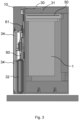
- Figures 3 and 4 respectively show the dispensing duct 30 in the rest position and in the activated position.
- the envelope 2 is not illustrated in the constraining position, it is evident from the position of the engagement seats 50 that in Figure 4 the duct in activated position is in a position such that it would have pierced the taut wall portion 21 and would have opened inside the envelope 2, had the latter been present.
- Figure 5 illustrates an assembly view from the outside of the safe provided with the system which is the subject matter of the present invention, comprising a box 10 and a chamber 11 for housing the components disclosed above.
- Figure 6 illustrates an embodiment wherein the compartment 1 is internally provided with one or more flaps 7 for retaining the envelope 2 in a complete filling condition by said fast-curing foam.
- the flaps face away from the opening of the compartment.
- the flaps can be of any shape and size.
- the flaps are integral with the walls of the compartment 1, alternatively or in combination they can consist of elements applied to the internal walls of the compartment 1.
- Figures 7, 8 , 9, and 10 illustrate a second embodiment of a nine-compartment safe.
- Figure 7 shows an external assembly view of the safe provided with the system which is the subject matter of the present invention, comprising a box 10 divided into nine compartments and a chamber 11 for housing the components disclosed above.
- Figure 8 shows the components of the system in a manner corresponding to that illustrated in Figure 2 .
- the connections have not been shown.
- the transmission plate 62 is peculiarly shaped to operate the nine dispensing ducts 30 at the same time.
- a single electric motor 60 is provided and two springs 61 are provided.
- Figures 3 and 4 respectively show the dispensing ducts 30 in the nine compartments 1 in the rest positions and in the activated positions.
Landscapes
- Physics & Mathematics (AREA)
- General Physics & Mathematics (AREA)
- Burglar Alarm Systems (AREA)
Abstract
Description
- The present invention relates to an anti-burglary system for at least one closed compartment adapted to contain one or more goods enclosed in at least one envelope having walls of flexible material, which system comprises one or more burglary sensors, dispensing means inside the compartment of a fast-curing foam having a dispensing duct which opens inside the compartment and means for detecting and/or processing the signals generated by the sensors configured to generate an activation signal of the dispensing means.
- Anti-burglary systems using fast-curing foam are currently known in the state of the art.
- Such systems constitute safety systems for preserving valuables inside a valuables compartment, immobilizing them by means of the use of foams or very resistant resins which are poured inside the compartment, react in contact with the air and form solid compounds which occupy the entire compartment and make it impossible to withdraw the valuables, at least in short and acceptable times for the robbers.
- The foam dispensing means typically comprise two tanks of a first and a second substance, which substances generate a fast-curing foam if mixed together. The outlets of the two tanks are therefore connected to a mixing chamber from which at least one dispenser branches out which opens inside the closed compartment.
- The two independent tanks keep the substances separated from each other, which substances remain in the liquid phase until the moment of mixing. The chemical reaction of the foam formation is instead irreversible, rendering the valuables inaccessible once the solidified foam compartment is filled.
- Such a system is disclosed for example by
GB 2091925 A - The fast-curing foam is typically a polyurethane foam obtained from the mixture of one or more polyols with one or more isocyanates.
- Such systems are currently used in safes but also in armoured trucks, where the value transported and the risk of robbery require a particularly high level of security.
- The goods are often transported in bags of flexible material, especially with regard to cash. The anti-burglary systems typically used for this type of goods are systems which render the good unusable, for example ink systems.
- The foam systems typically make it possible to prevent the good from being withdrawn and are therefore used for lower values because they are considered to constitute a lesser deterrent with respect to the systems which render the good unusable.
-
IT201800010365A1 -
EP4024356A1 , by the same applicant, discloses an anti-burglary system for closed compartments comprising means for dispensing a fast-curing foam. The foam dispensing means comprise at least two tanks of a first and a second substance, which generate a fast-curing foam when mixed together. Means for propelling the liquids emitted from the tanks are included, the outlets of the two tanks are connected to a mixing chamber from which at least one dispenser branches out which opens inside the compartment. The tanks are comprised in respective removable units, a box provided with seats for housing the removable units is included. Automated means are also provided for connecting each tank to the propulsion means and to the mixing chamber, which connecting means are housed in the box. -
US4461222A discloses a system which provides, in the event of an alarm being activated (e.g., by a sensor) due to an attempted break-in into a protected space, such as a safe or an armoured room, for a fast-curing foam to be placed around or inside the space to be protected. The expanding foam can also be used to push further door barrier means into position. The foam can be produced by mixing two components which react with each other. The components can be stored in tanks, where they occupy little volume until the alarm is activated. The components are mixed in a mixing head and introduced into the space through a nozzle. - There is currently a need not met by the state of the art for a foam system which not only prevents the withdrawal of the good, but also makes it unusable.
- The present invention aims to overcome the drawbacks of the currently known systems and to obtain a system which allows to both prevent the withdrawal of the good and to render the good unusable.
- The present invention achieves the aforesaid objects with a system as described at the outset, which comprises:
- a rigid element applicable to the envelope and shaped so as to create a taut wall portion of the envelope and
- fixing means of the rigid element inside the compartment in a position constraining the envelope to the compartment.
- The dispensing duct is provided with a cutting end and positioned near the constraining position of the envelope and movable from a rest position wherein it is not in contact with the envelope to an activated position wherein it passes through the taut wall portion and opens inside the envelope.
- Automatic means for operating the dispensing duct are provided, said detection and/or processing means of the signals generated by the sensors configured to generate an activation signal of the operating means of the dispensing duct prior to the generation of said activation signal of the dispensing means.
- Thereby, the fast-curing foam is not only dispensed into the compartment wherein the goods contained in an envelope, but is dispensed directly inside the envelope contained inside such a compartment. This not only allows to prevent the good from being withdrawn, but also to render it unusable.
- In an embodiment, the rigid element is shaped with a closed or open frame such as to identify an internal space for identifying said taut wall portion of the envelope, the rigid element being provided with two opposite retaining sides adapted to cooperate with said fixing means, which fixing means comprise engagement seats of said sides.
- The rigid element thus carries out the dual function of holding taut the wall portion of the envelope which is adapted to be pierced by the cutting end of the dispensing duct and of providing a retaining element of the envelope in a predefined position inside the compartment. This position is identified so that it allows easy piercing by the cutting end of the dispensing duct of the wall portion
- In an embodiment, the engagement seats comprise two slots facing each other at a distance substantially corresponding to the distance between the retaining sides, so that the rigid element is slidably insertable inside said engagement seats.
- Preferably, the slots have a thickness such as to house and retain therein at least part of the retaining sides of the rigid element.
- The sliding insertion in the engagement seats allows an easy insertion and in the same manner an easy removal of the envelope inside the compartment in the correct position for the operation of the system, to the benefit of the operation of the valuables compartment and the anti-burglary system by the operators.
- In a further embodiment, the rigid element is inside the envelope.
- The rigid element can be left free inside the envelope and the operator must only identify it to the touch and insert it in the engagement seats, constraining the entire envelope in position.
- Alternatively, the rigid element can be fixed internally to the walls of the envelope in a predefined position.
- In a further embodiment, the rigid element is applied on the outside of the envelope.
- The rigid element can be fixed externally or internally to the envelope by means of fixing means known to the person skilled in the art, such as gluing, welding, stitching, or the like.
- Alternatively, the rigid element is embedded inside the wall of the envelope.
- According to an executive example, the operating means comprise an electric motor.
- In a further executive example, alternatively or in combination, the operating means comprise elastic means, preferably at least one spring.
- In a first embodiment, when operated, the electric motor pushes the dispensing duct towards the rest position, while the spring stably biases the dispensing duct towards the activated position. The motor is therefore initially operated to bring the dispensing duct to the rest position. Means are provided for retaining the dispensing duct in the rest position, known to the person skilled in the art, which retaining means can be deactivated when the system is activated following the detection of an attempted burglary. At this point, the spring pushes the free dispensing duct towards the activated position. The retaining means of the dispensing duct can consist of the motor itself, the dispensing duct being detachable from the motor upon the activation of the system following the detection of an attempted burglary.
- In a second embodiment variant, the spring stably biases the dispensing duct towards the rest position, keeping it stably in such an inactive condition.
- When the system is activated following the detection of an attempted burglary, the electric motor is operated and pushes the dispensing duct towards the activated position, overcoming the resistance of the spring.
- In a third embodiment variant, only one motor is provided which initially moves the dispensing duct to the rest position and, when the system is activated following detection of an attempted burglary, it is operated and pushes the dispensing duct towards the activated position, overcoming the resistance of the spring.
- In a fourth embodiment variant, only one spring is provided which stably biases the dispensing duct towards the activated position. The dispensing duct is previously brought to the rest position manually. Means are provided for retaining the dispensing duct in the rest position, known to the person skilled in the art, which retaining means can be deactivated when the system is activated following the detection of an attempted burglary. At this point, the spring pushes the free dispensing duct towards the activated position.
- In a further embodiment, the compartment is internally provided with one or more envelope retaining flaps in a complete filling condition by said fast-curing foam.
- This makes it possible to prevent the removal of the foam-inflated envelope from the compartment, since the envelope when inflated has taken on a shape complementary to the flaps, stably coupling thereto.
- According to a further embodiment, the cutting end of the dispensing duct consists of an acute angle cut of the dispensing duct itself.
- An object of the present invention is further an anti-burglary method for at least one closed compartment adapted to contain one or more goods enclosed in at least one envelope having walls of flexible material comprising the dispensing of fast-curing foam inside the compartment by means of a dispensing duct which opens into the compartment when an attempted burglary is detected,
characterized in that it comprises the following steps: - a) applying a rigid element to the envelope to create a taut wall portion of the envelope;
- b) positioning the envelope inside the compartment and fixing the rigid element inside the compartment in a position constraining the envelope to the compartment, the dispensing duct being positioned at said constraining position of the envelope;
- c) detecting an attempted burglary;
- d) moving the dispensing duct from a rest position wherein it is not in contact with the envelope to an activated position wherein it passes through the taut wall portion and opens inside the envelope;
- e) piercing the taut wall portion of the envelope by said dispensing duct, the dispensing duct being provided with a cutting end;
- f) reaching the activated position of the dispensing duct;
- g) activating the dispensing of the fast-curing foam inside the envelope.
- According to an embodiment, dispensing the foam inside the envelope causes an expansion of the envelope up to a contact of the envelope with one or more walls of the compartment.
- This makes it difficult, if not impossible, to remove the envelope and the goods from the compartment, since the inflated envelope cannot pass through a breach in the walls in the compartment or the opening passage of any door, even if the latter could be opened.
- An object of the present invention is further a safe provided with a safety compartment and comprising the system comprising one or more of the features described above.
- These and other features and advantages of the present invention will become clearer from the following disclosure of some embodiment examples illustrated in the accompanying drawings wherein:
-
Fig. 1 illustrates a conceptual schematic view of the invention; -
Fig. 2 illustrates a view of an embodiment of the system for a single-compartment safe; -
Fig. 3 illustrates a sectional view with the dispensing duct in the rest position; -
Fig. 4 illustrates a sectional view with the dispensing duct in the activated position; -
Fig. 5 illustrates an external view of the single-compartment safe provided with the system; -
Fig. 6 illustrates a sectional view from above of the compartment; -
Fig. 7 illustrates an external view of a nine-compartment safe provided with the system; -
Fig. 8 illustrates a view of an embodiment of the system for the nine-compartment safe; -
Fig. 9 illustrate a sectional view with the dispensing ducts in the rest position; -
Fig. 10 illustrates a sectional view with the dispensing ducts in the activated position. - The figures illustrate two preferred embodiments of the anti-burglary system according to the present invention, respectively with one
compartment 1 closed and with ninecompartments 1 closed. - The invention is illustrated for safes, but it is obvious to the person skilled in the art that the same concepts can be applied, mutatis mutandis, to any structure provided with a security compartment adapted to contain
valuable goods 20. -
Figure 1 shows a conceptual view of the invention. Thegoods 20 are enclosed in anenvelope 2 having walls of flexible material. Such an envelope can be of any material, preferably it is a polymeric envelope of the type typically used for the transport of cash. - The system comprises one or more burglary sensors, not illustrated in the figure. It is possible to provide a single sensor or a plurality of sensors adapted to detect the variations of some physical parameters related to the interior of the
compartment 1 and/or its walls, which physical parameters are indicative of modification, opening, cutting or breaking through one or more of the delimiting walls of thecompartment 1 and/or part thereof. The sensors can be provided in all the delimiting walls of thevaluables compartment 1. The sensors can be of any type currently known. - In a preferred embodiment, the sensors are shaped in a plurality of branches, which branches are arranged so that the distance therebetween is always less than a predetermined maximum distance, such as not to allow openings larger than those which allow the removal of the
valuable goods 20 stored in thecompartment 1. - The system further comprises means for detecting and/or processing the signals generated by the sensors, also not illustrated in the figures. Such means are configured for generating an activation signal of dispensing means 3 of a fast-curing foam inside the
compartment 1 when an attempted burglary is detected. - The foam dispensing means 3 inside the
compartment 1 comprise a dispensingduct 30 which opens inside thecompartment 1. -
Multiple envelopes 2 and/or more than one dispensingduct 30 can be provided inside asingle compartment 1. - A
rigid element 4 is provided which is applicable to theenvelope 2 and shaped so as to create a taut wall portion 21 of theenvelope 2. Fixing means 5 of therigid element 40 are provided inside thecompartment 1 in a position constraining theenvelope 2 to thecompartment 1. - The
rigid element 4 can be free inside theenvelope 2, or fixed internally to the walls of theenvelope 2 at a predetermined position, or applied to the outside of theenvelope 2, or embedded inside the wall of theenvelope 2. Therigid element 4 can be fixed to theenvelope 2 by fixing means known to the person skilled in the art, such as gluing, welding, stitching, or the like. - The
rigid element 4 is shaped with a closed frame such as to identify aninternal space 40 for identifying the taut wall portion 21 of theenvelope 2. In particular, therigid element 4 is provided with two opposite retainingsides 41 adapted to cooperate with the fixing means 5, which fixing means 5 compriseengagement seats 50 of thesides 41. - The
rigid element 4 can also be formed with an open frame, for example with a U-shape. - The engagement seats 50 comprise two slots facing each other at a distance substantially corresponding to the distance between the retaining
sides 41, such that therigid element 4 is slidably insertable inside the engagement seats 50, in the direction indicated by the arrow. - Advantageously, the engagement seats 50 are provided with a sensor of the inserted condition of the
rigid element 4 in the engagement seats 50. This allows to notify the detection and/or processing means that theenvelope 2 has been correctly inserted in position inside thecompartment 1 and the system can operate without problems. - The dispensing
duct 30 is provided with a cuttingend 31, preferably consisting of an acute angle cut. It is however possible in combination or alternatively to provide additional cutting elements to be connected in the dispensing head of theduct 30. - The dispensing
duct 30 is positioned near the constraining position of theenvelope 2 and is movable, as indicated by the double arrow, from a rest position wherein it is not in contact with theenvelope 2 to an activated position wherein it passes through the taut wall portion 21 and opens inside theenvelope 2. - The system comprises automatic means for operating 6 the movement of the dispensing
duct 30. - The means for detecting and/or processing the signals generated by the sensors are configured to generate an activation signal of the operating means 6 of the dispensing
duct 30 prior to the generation of the activation signal of the dispensing means 3. This allows the movement of the dispensingduct 30 to be automatically operated prior to dispensing the foam. - The operation of the system therefore includes an initial application of the
rigid element 4 to theenvelope 2 with the methodologies disclosed above, for the creation of the taut wall portion 21 of theenvelope 2. Theenvelope 2 is then positioned inside thecompartment 1 by fixing therigid element 4 inside thecompartment 1 in the constraining position of theenvelope 2 to thecompartment 1. - When an attempted burglary is detected, a movement of the dispensing
duct 30 from the rest position to the activated position is operated. - In this step, the dispensing
duct 30 pierces the taut wall portion 21 of theenvelope 2 and reaches the activated position, wherein it opens inside theenvelope 2. - The dispensing of the fast-curing foam inside the
envelope 2 is then activated. - Preferably, dispensing the foam inside the
envelope 2 causes an expansion of theenvelope 2 up to a contact of theenvelope 2 with one or more walls of thecompartment 1. - As illustrated in
Figure 2 , the foam dispensing means 2 inside thecompartment 1 comprise at least twotanks 34 of a first and a second substance, which substances generate a fast-curing foam when mixed together. Means are provided for propelling the liquids in output from thetanks 34 and the outlets of the twotanks 34 are connected to a mixing chamber from which the dispensingduct 30 branches out, which opens inside theclosed compartment 1. - Preferably the propulsion means comprise a pressurized gas, in particular each
tank 34 is connected or connectable to a respective supply duct of said gas coming from a tank ofpressurized gas 32 closed by closing means, preferably asolenoid valve 33. The opening of the closing means is controlled by said dispensing activation signal. - However, it is possible to provide propulsion means comprising pneumatic or mechanical thrust actuators.
- The hydraulic connections of the dispensing means 5 are schematically shown by arrows in
Figure 2 . -
Figure 2 also illustrates the operating means 6 of the dispensingduct 30. Such means preferably comprise anelectric motor 60 and aspring 61, both connected with the dispensingduct 30 by means of atransmission plate 62. - When operated, the
electric motor 60 pushes the dispensingduct 30 towards the rest position, while thespring 61 stably biases the dispensingduct 30 towards the activated position. - The
motor 60 is therefore initially operated to bring the dispensingduct 30 to the rest position. Means are provided for retaining the dispensingduct 30 in the rest position, known to the person skilled in the art, which retaining means can be deactivated when the system is activated following the detection of an attempted burglary. At this point thespring 61 pushes thefree dispensing duct 30 towards the activated position. -
Figures 3 and4 respectively show the dispensingduct 30 in the rest position and in the activated position. Although theenvelope 2 is not illustrated in the constraining position, it is evident from the position of the engagement seats 50 that inFigure 4 the duct in activated position is in a position such that it would have pierced the taut wall portion 21 and would have opened inside theenvelope 2, had the latter been present. -
Figure 5 illustrates an assembly view from the outside of the safe provided with the system which is the subject matter of the present invention, comprising abox 10 and achamber 11 for housing the components disclosed above. -
Figure 6 illustrates an embodiment wherein thecompartment 1 is internally provided with one ormore flaps 7 for retaining theenvelope 2 in a complete filling condition by said fast-curing foam. Preferably the flaps face away from the opening of the compartment. The flaps can be of any shape and size. Preferably the flaps are integral with the walls of thecompartment 1, alternatively or in combination they can consist of elements applied to the internal walls of thecompartment 1. -
Figures 7, 8 ,9, and 10 illustrate a second embodiment of a nine-compartment safe. -
Figure 7 shows an external assembly view of the safe provided with the system which is the subject matter of the present invention, comprising abox 10 divided into nine compartments and achamber 11 for housing the components disclosed above. -
Figure 8 shows the components of the system in a manner corresponding to that illustrated inFigure 2 . The connections have not been shown. Thetransmission plate 62 is peculiarly shaped to operate the nine dispensingducts 30 at the same time. A singleelectric motor 60 is provided and twosprings 61 are provided. - Thereby, the system is activated at the same time for all nine compartments. However, nine parallel systems can be provided, each of which can be activated independently of the others.
-
Figures 3 and4 respectively show the dispensingducts 30 in the ninecompartments 1 in the rest positions and in the activated positions.
Claims (10)
- Anti-burglary system for at least one closed compartment (1) adapted to contain one or more goods (20) enclosed in at least one envelope (2) having walls of flexible material, which system comprises one or more burglary sensors, dispensing means (3) inside the compartment (1) of a fast-curing foam having a dispensing duct (30) which opens inside the compartment (1) and means for detecting and/or processing the signals generated by the sensors configured to generate an activation signal of the dispensing means (3),
characterized in that
the system comprises a rigid element (4) applicable to the envelope (2) and shaped so as to create a taut wall portion (21) of the envelope (2) and fixing means (5) of the rigid element (40) inside the compartment (1) in a constraining position of the envelope (2) to the compartment (1), the dispensing duct (30) being provided with a cutting end (31) and positioned near the constraining position of the envelope (2) and movable from a rest position wherein it is not in contact with the envelope (2) to an activated position wherein it passes through the taut walls portion (21) and opens inside the envelope (2), there being provided automatic operating means (6) of the dispensing duct (30), said means being for detecting and/or processing the signals generated by the sensors configured to generate an activation signal of the operating means (6) of the dispensing duct (30) prior to the generation of said activation signal of the dispensing means (3). - System according to claim 1, wherein the rigid element (4) is shaped with a closed or open frame such as to identify an internal space (40) for identifying said taut wall portion (21) of the envelope (2), the rigid element (4) being provided with two opposite retaining sides (41) adapted to cooperate with said fixing means (5), which fixing means (5) comprise engagement seats (50) of said sides (41).
- System according to claim 2, wherein the engagement seats (50) comprise two slots facing each other at a distance substantially corresponding to the distance between the retaining sides (41), such that the rigid element (4) is slidably insertable inside said engagement seats (50).
- System according to one or more of the preceding claims, wherein the rigid element (4) is inside the envelope (2).
- System according to one or more of claims 1 to 3, wherein the rigid element (4) is applied outside the envelope (2).
- System according to one or more of the preceding claims, wherein the operating means comprise an electric motor (60).
- System according to one or more of the preceding claims, wherein the compartment (1) is internally provided with one or more flaps (7) for retaining the envelope (2) in a complete filling condition by said fast-curing foam.
- System according to one or more of the preceding claims, wherein the cutting end (31) of the dispensing duct (30) consists of an acute angle cut.
- Anti-burglary method for at least one closed compartment (1) adapted to contain one or more goods (20) enclosed in at least one envelope (2) having walls of flexible material, which method comprises dispensing fast-curing foam inside the compartment (1) by means of a dispensing duct (30) which opens inside the compartment (1) when an attempted burglary is detected,
characterized in that it comprises the following steps:a) applying a rigid element (4) to the envelope (2) to create a taut wall portion (21) of the envelope (2);b) positioning the envelope (2) inside the compartment (1) and fixing the rigid element (4) inside the compartment (1) in a position constraining the envelope (2) to the compartment (1), the dispensing duct (30) being positioned at said constraining position of the envelope (2);c) detecting an attempted burglary;d) moving the dispensing duct (30) from a rest position wherein it is not in contact with the envelope (2) to an activated position wherein it passes through the taut wall portion (21) and opens inside the envelope (2);e) piercing the taut wall portion (21) of the envelope (2) by said dispensing duct (30), the dispensing duct being provided with a cutting end (31);f) reaching the activated position of the dispensing duct (30);g) activating the dispensing of the fast-curing foam inside the envelope (2). - Method according to claim 9, wherein the dispensing of the foam inside the envelope causes an expansion of the envelope (2) up to a contact of the envelope (2) with one or more walls of the compartment (1).
Applications Claiming Priority (1)
| Application Number | Priority Date | Filing Date | Title |
|---|---|---|---|
| IT102023000017898A IT202300017898A1 (en) | 2023-08-30 | 2023-08-30 | ANTI-BURGLARY SYSTEM |
Publications (3)
| Publication Number | Publication Date |
|---|---|
| EP4517709A1 true EP4517709A1 (en) | 2025-03-05 |
| EP4517709B1 EP4517709B1 (en) | 2026-02-04 |
| EP4517709C0 EP4517709C0 (en) | 2026-02-04 |
Family
ID=88778314
Family Applications (1)
| Application Number | Title | Priority Date | Filing Date |
|---|---|---|---|
| EP24197206.6A Active EP4517709B1 (en) | 2023-08-30 | 2024-08-29 | Anti-burglary system for a closed compartment. |
Country Status (2)
| Country | Link |
|---|---|
| EP (1) | EP4517709B1 (en) |
| IT (1) | IT202300017898A1 (en) |
Citations (3)
| Publication number | Priority date | Publication date | Assignee | Title |
|---|---|---|---|---|
| GB2091925A (en) | 1981-01-28 | 1982-08-04 | Fichet Bauche | Installation for protection against break-ins |
| IT201800010365A1 (en) | 2018-11-15 | 2020-05-15 | Bv Spumablock Srl | Anti-burglary device |
| EP4024356A1 (en) | 2020-12-30 | 2022-07-06 | BV Spumablock Srl | Anti-burglary system |
-
2023
- 2023-08-30 IT IT102023000017898A patent/IT202300017898A1/en unknown
-
2024
- 2024-08-29 EP EP24197206.6A patent/EP4517709B1/en active Active
Patent Citations (4)
| Publication number | Priority date | Publication date | Assignee | Title |
|---|---|---|---|---|
| GB2091925A (en) | 1981-01-28 | 1982-08-04 | Fichet Bauche | Installation for protection against break-ins |
| US4461222A (en) | 1981-01-28 | 1984-07-24 | Fichet-Bauche | Installation for protection against break-ins |
| IT201800010365A1 (en) | 2018-11-15 | 2020-05-15 | Bv Spumablock Srl | Anti-burglary device |
| EP4024356A1 (en) | 2020-12-30 | 2022-07-06 | BV Spumablock Srl | Anti-burglary system |
Also Published As
| Publication number | Publication date |
|---|---|
| IT202300017898A1 (en) | 2025-03-02 |
| EP4517709B1 (en) | 2026-02-04 |
| EP4517709C0 (en) | 2026-02-04 |
Similar Documents
| Publication | Publication Date | Title |
|---|---|---|
| US7428873B1 (en) | Security system | |
| EP0914538B1 (en) | Device for dispensing a liquid onto valuables | |
| ES2256021T3 (en) | SECURITY CABINET, SECURITY UNIT AND COMBINED COLLECTION UNIT AND ATM INCLUDING A PROVISION OF THIS TYPE. | |
| US4461222A (en) | Installation for protection against break-ins | |
| EP2510506B1 (en) | A security apparatus | |
| US20040154500A1 (en) | High pressure smudging device | |
| EP0623902A2 (en) | Device for bank note containers | |
| US9406208B2 (en) | Mobile cash transport system with tampering triggered ink deployment | |
| EP2347078B1 (en) | A security apparatus and method for storing or transporting valuables | |
| US3344757A (en) | Arrangement for the safe conveyance of bills and notes | |
| EP4517709B1 (en) | Anti-burglary system for a closed compartment. | |
| EP1499787B1 (en) | Spoiling agent delivery system | |
| EP4024356B1 (en) | Anti-burglary system | |
| US20070251431A1 (en) | Protection method and protection system for valuables | |
| EP1961902A1 (en) | Rack for transporting valuables | |
| JP4546096B2 (en) | Method and apparatus for valuable space | |
| IT201800010365A1 (en) | Anti-burglary device | |
| GB2491409A (en) | Multi-component spoiling agent dispensing system | |
| EP2406451A1 (en) | A security apparatus | |
| EP0397096A1 (en) | Foam producing antirobbery device for armoured trucks carrying valuables and the like | |
| EP1462021A1 (en) | Security containers | |
| EP4006853B1 (en) | Banknote drawer for banknotes or values for atm or bancomat | |
| US8171865B2 (en) | Method and device related to an alarmed value space | |
| GB2079847A (en) | Security containers | |
| WO2006008442A2 (en) | Security clip |
Legal Events
| Date | Code | Title | Description |
|---|---|---|---|
| PUAI | Public reference made under article 153(3) epc to a published international application that has entered the european phase |
Free format text: ORIGINAL CODE: 0009012 |
|
| STAA | Information on the status of an ep patent application or granted ep patent |
Free format text: STATUS: THE APPLICATION HAS BEEN PUBLISHED |
|
| AK | Designated contracting states |
Kind code of ref document: A1 Designated state(s): AL AT BE BG CH CY CZ DE DK EE ES FI FR GB GR HR HU IE IS IT LI LT LU LV MC ME MK MT NL NO PL PT RO RS SE SI SK SM TR |
|
| STAA | Information on the status of an ep patent application or granted ep patent |
Free format text: STATUS: REQUEST FOR EXAMINATION WAS MADE |
|
| GRAP | Despatch of communication of intention to grant a patent |
Free format text: ORIGINAL CODE: EPIDOSNIGR1 |
|
| STAA | Information on the status of an ep patent application or granted ep patent |
Free format text: STATUS: GRANT OF PATENT IS INTENDED |
|
| 17P | Request for examination filed |
Effective date: 20250806 |
|
| RIC1 | Information provided on ipc code assigned before grant |
Ipc: G08B 15/02 20060101AFI20250814BHEP Ipc: E05G 1/14 20060101ALI20250814BHEP Ipc: G08B 13/14 20060101ALN20250814BHEP |
|
| INTG | Intention to grant announced |
Effective date: 20250825 |
|
| GRAS | Grant fee paid |
Free format text: ORIGINAL CODE: EPIDOSNIGR3 |
|
| GRAA | (expected) grant |
Free format text: ORIGINAL CODE: 0009210 |
|
| STAA | Information on the status of an ep patent application or granted ep patent |
Free format text: STATUS: THE PATENT HAS BEEN GRANTED |
|
| AK | Designated contracting states |
Kind code of ref document: B1 Designated state(s): AL AT BE BG CH CY CZ DE DK EE ES FI FR GB GR HR HU IE IS IT LI LT LU LV MC ME MK MT NL NO PL PT RO RS SE SI SK SM TR |
|
| REG | Reference to a national code |
Ref country code: CH Ref legal event code: F10 Free format text: ST27 STATUS EVENT CODE: U-0-0-F10-F00 (AS PROVIDED BY THE NATIONAL OFFICE) Effective date: 20260204 Ref country code: GB Ref legal event code: FG4D |
|
| REG | Reference to a national code |
Ref country code: DE Ref legal event code: R096 Ref document number: 602024002398 Country of ref document: DE |
|
| REG | Reference to a national code |
Ref country code: IE Ref legal event code: FG4D |
|
| U01 | Request for unitary effect filed |
Effective date: 20260226 |
|
| U07 | Unitary effect registered |
Designated state(s): AT BE BG DE DK EE FI FR IT LT LU LV MT NL PT RO SE SI Effective date: 20260304 |