EP4517664A1 - Relative angle detection device for coupled vehicles - Google Patents
Relative angle detection device for coupled vehicles Download PDFInfo
- Publication number
- EP4517664A1 EP4517664A1 EP23795919.2A EP23795919A EP4517664A1 EP 4517664 A1 EP4517664 A1 EP 4517664A1 EP 23795919 A EP23795919 A EP 23795919A EP 4517664 A1 EP4517664 A1 EP 4517664A1
- Authority
- EP
- European Patent Office
- Prior art keywords
- vehicle
- towed
- relative angle
- towing
- detection device
- Prior art date
- Legal status (The legal status is an assumption and is not a legal conclusion. Google has not performed a legal analysis and makes no representation as to the accuracy of the status listed.)
- Pending
Links
Images



Classifications
-
- G—PHYSICS
- G06—COMPUTING OR CALCULATING; COUNTING
- G06T—IMAGE DATA PROCESSING OR GENERATION, IN GENERAL
- G06T7/00—Image analysis
- G06T7/60—Analysis of geometric attributes
-
- G—PHYSICS
- G06—COMPUTING OR CALCULATING; COUNTING
- G06T—IMAGE DATA PROCESSING OR GENERATION, IN GENERAL
- G06T7/00—Image analysis
- G06T7/70—Determining position or orientation of objects or cameras
- G06T7/73—Determining position or orientation of objects or cameras using feature-based methods
-
- B—PERFORMING OPERATIONS; TRANSPORTING
- B60—VEHICLES IN GENERAL
- B60D—VEHICLE CONNECTIONS
- B60D1/00—Traction couplings; Hitches; Draw-gear; Towing devices
- B60D1/01—Traction couplings or hitches characterised by their type
- B60D1/06—Ball-and-socket hitches
-
- B—PERFORMING OPERATIONS; TRANSPORTING
- B60—VEHICLES IN GENERAL
- B60D—VEHICLE CONNECTIONS
- B60D1/00—Traction couplings; Hitches; Draw-gear; Towing devices
- B60D1/24—Traction couplings; Hitches; Draw-gear; Towing devices characterised by arrangements for particular functions
- B60D1/245—Traction couplings; Hitches; Draw-gear; Towing devices characterised by arrangements for particular functions for facilitating push back or parking of trailers
-
- B—PERFORMING OPERATIONS; TRANSPORTING
- B60—VEHICLES IN GENERAL
- B60D—VEHICLE CONNECTIONS
- B60D1/00—Traction couplings; Hitches; Draw-gear; Towing devices
- B60D1/58—Auxiliary devices
- B60D1/62—Auxiliary devices involving supply lines, electric circuits or the like
-
- G—PHYSICS
- G01—MEASURING; TESTING
- G01B—MEASURING LENGTH, THICKNESS OR SIMILAR LINEAR DIMENSIONS; MEASURING ANGLES; MEASURING AREAS; MEASURING IRREGULARITIES OF SURFACES OR CONTOURS
- G01B11/00—Measuring arrangements characterised by the use of optical techniques
- G01B11/26—Measuring arrangements characterised by the use of optical techniques for measuring angles or tapers; for testing the alignment of axes
-
- G—PHYSICS
- G06—COMPUTING OR CALCULATING; COUNTING
- G06T—IMAGE DATA PROCESSING OR GENERATION, IN GENERAL
- G06T2207/00—Indexing scheme for image analysis or image enhancement
- G06T2207/30—Subject of image; Context of image processing
- G06T2207/30204—Marker
-
- G—PHYSICS
- G06—COMPUTING OR CALCULATING; COUNTING
- G06T—IMAGE DATA PROCESSING OR GENERATION, IN GENERAL
- G06T2207/00—Indexing scheme for image analysis or image enhancement
- G06T2207/30—Subject of image; Context of image processing
- G06T2207/30248—Vehicle exterior or interior
- G06T2207/30252—Vehicle exterior; Vicinity of vehicle
Definitions
- the present invention relates to relative angle detection devices for combination vehicles that are used in combination vehicles in which a towed vehicle is towed by a towing vehicle and that detect a relative angle of the towed vehicle with respect to the towing vehicle.
- a combination vehicle which is composed of a towed vehicle and a towing vehicle that are connected to each other and which can detect a hitch angle that is an angle of the towed vehicle with respect to the towing vehicle when the combination vehicle is viewed from above.
- a trailering assist system described in PTL 1 captures an image of a target on a towed vehicle (trailer) by a camera disposed at the rear of a towing vehicle and detects a hitch angle by analyzing the captured image.
- a marker with a predetermined shape, such as an icon, provided on the front of the towed vehicle, is used as the target.
- FIG. 1 of PTL 1 shows a panel with a cross-shaped figure on it as a target.
- an object of the present invention is to provide a relative angle detection device for a combination vehicle that can detect a relative angle of a towed vehicle with respect to a towing vehicle without installing on the towed vehicle a marker to be captured to detect the relative angle of the towed vehicle with respect to the towing vehicle.
- the present invention provides a relative angle detection device for a combination vehicle.
- the relative angle detection device is used in the combination vehicle in which a towing vehicle and a towed vehicle are connected by a towing-side connecting member and a towed-side connecting member.
- the relative angle detection device includes: an imaging device that captures an image of one of the towing vehicle and the towed vehicle from the other; a radiation device that emits marker light to a position where the image is to be captured by the imaging device; and an image analysis device that analyzes the image captured by the imaging device to detect a relative angle of the towed vehicle with respect to the towing vehicle.
- the present invention it is possible to detect the relative angle of the towed vehicle with respect to the towing vehicle without installing on the towed vehicle a marker to be captured to detect the relative angle of the towed vehicle with respect to the towing vehicle.
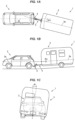
- FIGS. 1A, 1B, and 1C are schematic diagrams of a combination vehicle 1 with a relative angle detection device on which the relative angle detection device according to the embodiment of the present invention is mounted.
- FIG. 1A shows the combination vehicle 1 as viewed from above
- FIG. 1B shows the left side of the combination vehicle 1 in the forward travel direction.
- FIG. 1C shows the combination vehicle 1 as viewed from the rear.
- each of a center line 2a of a towing vehicle 2 in the front-rear direction of the towing vehicle 2 and a center line 3a of a towed vehicle 3 in the front-rear direction of the towed vehicle 3 is shown by a long dashed short dashed line.
- the combination vehicle 1 includes the towing vehicle 2 and the towed vehicle 3, and the towing vehicle 2 and the towed vehicle 3 are connected by a towing-side connecting member 4 and a towed-side connecting member 5.
- FIGS. 1A, 1B, and 1C show the case where the towed vehicle 3 is a box-shaped camper.
- the towed vehicle is not limited to this, and may be, for example, a boat trailer loaded with a boat.
- the towing vehicle 2 may be a manually driven vehicle in which a driver performs driving operations such as steering operations, or may be an autonomous vehicle in which part or all of driving operations are performed autonomously.
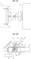
- FIG. 2A is a structure diagram showing an example of the structures of the towing-side connecting member 4 and the towed-side connecting member 5.
- FIG. 2B is a sectional view of the towing-side connecting member 4 and the towed-side connecting member 5 in a combined state.
- the towing-side connecting member 4 includes: a hitch cross member 41 disposed along the vehicle width direction of the towing vehicle 2; a pair of hitch side members 42 fixed to both ends of the hitch cross member 41; a ball mount 43 provided so as to protrude from the middle portion in the vehicle width direction of the hitch cross member 41 toward the rear side of the towing vehicle 2; a hitch pin 44 protruding upward from the ball mount 43; and a spherical hitch ball 45 integral with the upper end of the hitch pin 44.
- the hitch cross member 41 and the pair of hitch side members 42 are disposed inside a rear bumper 21 of the towing vehicle 2, and the ball mount 43, the hitch pin 44, and the hitch ball 45 are exposed to the rear side from the rear bumper 21.
- the pair of hitch side members 42 is fixed to a body of the towing vehicle 2 by a plurality of bolts.
- the towed-side connecting member 5 includes: a coupler 51 that covers the hitch ball 45; a latch mechanism 52 that retains the coupler 51 on the hitch ball 45; a rod-shaped tongue 53 with the coupler 51 fixed to its distal end; and a pair of side beams 54 extending in a direction tilted with respect to the longitudinal direction of the tongue 53.
- Each of the side beams 54 has its one end connected to the tongue 53.
- a proximal end of the tongue 53 and the other end of each of the pair of side beams 54 are connected to a chassis of the towed vehicle 3.
- the coupler 51 includes a cup portion 511 that holds the hitch ball 45.
- the latch mechanism 52 includes: a lever support 520; a lever 521 that is rotated with respect to the lever support 520; a latch plate 522 that faces an upper surface 51a of the coupler 51; a latch bar 523 that enters between the upper surface 51a of the coupler 51 and the latch plate 522 when the lever 521 is operated; a lock plate 524 that receives the hitch ball 45 from below; a coil spring 525 that biases the lock plate 524 downward; and a bolt 526 and a nut 527 that connect the latch plate 522 and the lock plate 524.
- the lock plate 524 is rotatable about a support pin 512 that is provided horizontally to the coupler 51.
- the lever 521 When the lever 521 is operated as shown by an arrow A in FIG. 2B , the latch plate 522 is lifted upward with respect to the coupler 51 by the latch bar 523, and the lock plate 524 retains the hitch ball 45.
- An inner surface 511a of the cup portion 511 of the coupler 51 is a concave spherical surface having a curvature corresponding to the curvature of a surface 45a of the hitch ball 45.
- the coupler 51 is swingable in any direction about the hitch ball 45 due to sliding between the inner surface 511a of the cup portion 511 and the surface 45a of the hitch ball 45.
- the relative angle of the towed vehicle 3 with respect to the towing vehicle 2 changes variously. Particularly when the combination vehicle 1 reverses with the towed vehicle 3 located on the front side in the direction of travel, the relative angle of the towed vehicle 3 with respect to the towing vehicle 2 serves as an important indicator when performing driving operations. For this reason, the relative angle detection device is used in the combination vehicle 1.
- the towing vehicle 2 is a manually driven vehicle (non-autonomous vehicle)
- an image showing the detection result from the relative angle detection device is displayed on a display installed inside a cabin of the towing vehicle 2, so that the driver is assisted in driving operations.
- the towing vehicle 2 is an autonomous vehicle
- the towing vehicle 2 is autonomously steered based on the detection result from the relative angle detection device.
- the relative angle of the towed vehicle 3 with respect to the towing vehicle 2 includes: a hitch angle that indicates tilt of the towed vehicle 3 in the horizontal direction with respect to the towing vehicle 2; a relative pitch angle that indicates tilt of the towed vehicle 3 in the up-down direction with respect to the towing vehicle 2; and a relative roll angle that is the difference between a roll angle of the towing vehicle 2 and a roll angle of the towed vehicle 3.
- FIG. 1A shows a hitch angle ⁇ h when the towed vehicle 3 is tilted to the left with respect to the towing vehicle 2.
- FIG. 1B shows a relative pitch angle ⁇ p when the towed vehicle 3 is tilted upward with respect to the towing vehicle 2.
- FIG. 1C shows a relative roll angle ⁇ r when the towed vehicle 3 is tilted clockwise with respect to the towing vehicle 2 as viewed from the rear of the combination vehicle 1.
- the relative angle detection device can detect at least the hitch angle and the relative pitch angle out of the hitch angle, the relative pitch angle, and the relative roll angle. Next, the configuration, placement, and operation of the relative angle detection device will be described.
- FIG. 3 is a block diagram showing functional configurations of a relative angle detection device 6.
- the relative angle detection device 6 includes: an imaging device 61 that captures an image of one of the towing vehicle 2 and the towed vehicle 3 from the other; a radiation device 62 that emits marker light to a position where the image is to be captured by the imaging device 61; and an image analysis device 63 that analyzes the image captured by the imaging device 61 to detect the relative angle of the towed vehicle 3 relative to the towing vehicle 2.
- the imaging device 61 captures the figure projected by the marker light emitted from the radiation device 62, and detects the relative angle of the towed vehicle 3 with respect to the towing vehicle 2 from the shape of the captured figure.
- the detection result of the relative angle is sent to, for example, a display device 7 of the towing vehicle 2, and as shown in FIG. 3 , an image showing the detection result from the relative angle detection device 6 is displayed on a display 71 inside the vehicle cabin.
- FIG. 3 shows a display example in which a bird's-eye view image 710 showing a graphic symbol 711 representing the towing vehicle 2 and a graphic symbol 712 representing the towed vehicle 3 in a tilted state according to the hitch angle detected by the relative angle detection device 6 is displayed in a first display area 71a of the display 71.
- a bird's-eye view image 710 showing a graphic symbol 711 representing the towing vehicle 2 and a graphic symbol 712 representing the towed vehicle 3 in a tilted state according to the hitch angle detected by the relative angle detection device 6 is displayed in a first display area 71a of the display 71.
- an image captured by the imaging device 61 is displayed in a second display area 71b of the display 71.
- the radiation device 62 emits the marker light at least when the combination vehicle 1 reverses.
- the radiation device 62 emits the marker light when, for example, a shift lever is shifted to reverse (R) range, and stops emitting the marker light when the shift lever is shifted from R range to a different range.
- the radiation device 62 may be configured to emit the marker light according to a switch operation by the driver. Even when the combination vehicle 1 moves forward, the state of the towed vehicle 3 may become unstable due to, for example, the slope of the road surface or a cross wind.
- the radiation device 62 emits the marker light according to a switch operation by the driver, and the relative angle detection device 6 detects the hitch angle, etc., so that the driver can be assisted in driving operations.
- the radiation device 62 starts and stops emitting the marker light according to a command signal from the autonomous driving device 8.
- FIG. 4 is a flowchart showing an example of the procedure of a process that is performed by the relative angle detection device 6.
- the relative angle detection device 6 repeatedly performs the process shown in this flowchart at a predetermined cycle of, for example, several milliseconds to several tens of milliseconds.
- the relative angle detection device 6 first determines whether to perform a process of detecting the relative angle of the towed vehicle 3 with respect to the towing vehicle 2 (step S1). As described above, this determination can be made according to, for example, a reverse driving operation or switch operation by the driver or a command signal from the autonomous driving device 8. When the result of this determination is Yes, the radiation device 62 emits the marker light (step S2), and the imaging device 61 captures the figure projected by the marker light (step S3). Information on the image captured by the imaging device 61 is sent to the image analysis device 63.
- the image analysis device 63 analyzes the image captured by the imaging device 61 to detect the relative angle of the towed vehicle 3 with respect to the towing vehicle 2 (step S4).
- the analysis in step S4 can be performed by, for example, storing in advance the shape of the marker light that would be obtained when all of the hitch angle, the relative pitch angle, and the relative roll angle are zero as a reference shape, comparing the reference shape with the shape of the marker light in the image captured by the imaging device 61 to obtain the amount of change in shape, and converting this amount of change to the relative angle.
- the relative angle in the current cycle may be detected by referring to the detection result of the relative angle in the previous cycle.
- step S1 when the result of the determination in step S1 is No, the radiation device 62 stops emitting the marker light (step S5), and the image analysis device 63 initializes the detection result of the relative angle (step S6).
- FIGS. 5A and 5B are illustrations showing the positions where the imaging device 61 and the radiation device 62 are disposed in the combination vehicle 1 according to a first example embodiment.
- FIG. 5A shows the rear side of the towing vehicle 2 as viewed from the towed vehicle 3.
- FIG. 5B shows the towing-side connecting member 4, the towed-side connecting member 5, part of the towing vehicle 2, and part of the towed vehicle 3, as viewed from the left side of the towing vehicle 2.
- the imaging device 61 and the radiation device 62 are mounted on the rear end of the towing vehicle 2. More specifically, the imaging device 61 and the radiation device 62 are mounted on the outer side of a backdoor 22 of the towing vehicle 2.
- the radiation device 62 is mounted at a position between a license plate 23 and a rear glass 221 of the backdoor 22.
- the imaging device 61 is disposed above the radiation device 62, and captures an image of the towed vehicle 3.
- the imaging device 61 is disposed directly above the radiation device 62. However, the position of the imaging device 61 may be shifted with respect to the radiation device 62 in the vehicle width direction of the towing vehicle 2.
- the figure projected by the marker light emitted from the radiation device 62 is a line segment of a predetermined length parallel to the vehicle width direction of the towing vehicle 2.
- FIG. 5A shows an angle of view VA indicating the imaging range of the imaging device 61 and a radiation range R of the marker light from the radiation device 62.
- FIG. 5B the direction of the marker light emitted from the radiation device 62 is shown by a long dashed short dashed line DL.
- the towed-side connecting member 5 and a road surface 9 on both sides of the towed-side connecting member 5 in the vehicle width direction of the towing vehicle 2 are included in the radiation range of the marker light from the radiation device 62.
- the radiation device 62 irradiates the tongue 53 of the towed-side connecting member 5.
- the present invention is not limited to this, and the radiation device 62 may irradiate, for example, the coupler 51.
- the angle of view VA of the imaging device 61 includes the entire radiation range R of the radiation device 62.
- the road surface 9 is, for example, the surface of a paved public road, but may be unpaved ground or the surface of a parking space in a parking lot.
- FIGS. 6A and 6B are illustrations each showing an image captured by the imaging device 61.
- the "right side” and the “left side” refer to the right side and left side of the image captured by the imaging device 61.
- FIG. 6A shows a state in which the towing vehicle 2 and the towed vehicle 3 are aligned in a straight line with a hitch angle of zero.
- FIG. 6B shows a state in which the towed vehicle 3 is tilted to the right with respect to the towing vehicle 2.
- the imaging device 61 is disposed above the radiation device 62. Therefore, in the image captured by the imaging device 61, a first irradiated portion 621 that indicates part of the marker light that is incident on the towed-side connecting member 5 appears above a second irradiated portion 622 that indicates part of the marker light that is incident on the road surface 9 on the left side of the towed-side connecting member 5 and a third irradiated portion 623 that indicates part of the marker light that is incident on the road surface 9 on the right side of the towed-side connecting member 5.
- L 0 indicates the total length of the first to third irradiated portions 621 to 623 in the left-right direction of the image captured by the imaging device 61
- L 1 indicates the length of the first irradiated portion 621
- L 2 indicates the length of the second irradiated portion 622
- L 3 indicates the length of the third irradiated portion 623. More specifically, the length L 1 is the length between the left end and right end of a portion of the tongue 53 that is irradiated by the radiation device 62.
- the length L 2 is the length from the left end of the road surface 9 irradiated by the radiation device 62 to the left end of the portion of the tongue 53 that is irradiated by the radiation device 62.
- the length L 3 is the length from the right end of the road surface 9 irradiated by the radiation device 62 to the right end of the portion of the tongue 53 that is irradiated by the radiation device 62.
- the length L 0 is the length from the left end to the right end of the road surface 9 irradiated by the radiation device 62.
- the lengths L 1 , L 2 , and L 3 are index values that indicate the position in the vehicle width direction of the towed-side connecting member 5 in the radiation range of the marker light (length L 0 ).
- the middle position in the left-right direction of the tongue 53 with respect to the reference position can be calculated by the arithmetic expression L 0 /2 - ((L 2 + L 1 /2)/(L 1 + L 2 + L 3 )) ⁇ L 0 . Since the positional relationships between the imaging device 61 and the radiation device 62, the hitch ball 45, etc. are known, the hitch angle can be obtained by calculation based on the above arithmetic expression.
- the image analysis device 63 thus detects the hitch angle of the combination vehicle 1 based on the position in the vehicle width direction of the towed-side connecting member 5 in the radiation range of the marker light.
- the distance D in the up-down direction between the first irradiated portion 621 and the second irradiated portion 622 and third irradiated portion 623 changes according to the relative pitch angle. Therefore, the relative pitch angle can be calculated based on this distance D.
- the distance D is an index value that indicates the difference in position in the front-rear direction of the towing vehicle 2 between the towed-side connecting member 5 and the road surface 9 that are irradiated with the marker light.
- the image analysis device 63 detects the relative pitch angle of the combination vehicle 1 based on the difference in position in the front-rear direction of the towing vehicle 2 between the towed-side connecting member 5 and the road surface 9 that are irradiated with the marker light.
- the image analysis device 63 acquires information on the image from the imaging device 61 at a predetermined cycle, calculates the hitch angle and the relative pitch angle, and outputs the hitch angle and the relative pitch angle as the detection result.
- the hitch angle increases, the marker light is also incident on the side surfaces in the left-right direction of the tongue 53, and therefore the length L 1 of the first irradiated portion 621 increases accordingly. Therefore, in the calculation for obtaining the hitch angle, it is necessary to correct the middle position in the left-right direction of the tongue 53 by, for example, using the hitch angle calculated in the previous cycle. This correction may be made by referring to map information that stores the relationship between the calculation result of the above arithmetic expression and the actual middle position in the left-right direction of the tongue 53.
- FIG. 7 is an illustration showing the positions where the imaging device 61 and the radiation device 62 are disposed in the combination vehicle 1 according to the second example embodiment.
- the imaging device 61 is attached to the rear end of the towing vehicle 2 as in the first example embodiment, but the radiation device 62 is attached to the towed-side connecting member 5.
- the radiation device 62 is fixed to the tongue 53 by a bracket 55, and irradiates the front end of the towed vehicle 3 obliquely upward.
- the radiation range of the marker light from the radiation device 62 is shown by two long dashed short dashed lines DL 1 , DL 2 .
- the imaging device 61 is attached to a position between the license plate 23 and the rear glass 221 of the backdoor 22, and is also used as a camera for a rear monitor.
- FIGS. 8A, 8B , 8C, and 8D are illustrations of the towed vehicle 3 irradiated with the marker light from the radiation device 62, as viewed from the towing vehicle 2.
- FIG. 8A shows a state in which all of the hitch angle, the relative pitch angle, and the relative roll angle are zero.
- FIG. 8B shows a state when the towed vehicle 3 is tilted to the right as viewed from the towing vehicle 2.
- FIG. 8C shows a state when the towed vehicle 3 is tilted upward.
- FIG. 8D shows a state when the towed vehicle 3 rolls counterclockwise.
- a projected figure 624 projected by the marker light emitted from the radiation device 62 is an ellipse whose major axis is in the vehicle width direction of the towing vehicle 2 and whose minor axis is in the up-down direction.
- D 11 indicates the longer diameter of the projected figure 624
- D 12 indicates the shorter diameter of the projected figure 624.
- the shape of the ellipse defined by the longer diameter D 11 and the shorter diameter D 12 is a reference shape of the projected figure 624.
- the image analysis device 63 stores the longer diameter D 11 and the shorter diameter D 12 .
- the shape of the projected figure 624 that is captured by the imaging device 61 is distorted, and its longer diameter D 21 becomes shorter than the longer diameter D 11 of the projected figure 624 shown in FIG. 8A .
- the difference between the longer diameter D 21 and the longer diameter D 11 is the amount of distortion of the projected figure 624 due to the change in hitch angle.
- the image analysis device 63 converts this amount of distortion to a hitch angle.
- the hitch angle of the combination vehicle 1 can thus be obtained. That is, in this example, the image analysis device 63 detects the hitch angle based on the size of the marker light captured by the imaging device 61 in the vehicle width direction of the towing vehicle 2.
- Whether the towed vehicle 3 is tilted to the right or to the left with respect to the towing vehicle 2 can be determined based on, for example, the difference of the shapes of the right and left ends of the captured projected figure 624 from the reference shape of the projected figure 624. This is for the following reason.
- the right end of the captured projected figure 624 becomes larger than the reference shape while the left end of the captured projected figure 624 becomes smaller than the reference shape, according to the distance from the imaging device 61.
- the shape of the projected figure 624 that is captured by the imaging device 61 is distorted, and its shorter diameter D 32 becomes shorter than the shorter diameter D 12 of the projected figure 624 shown in FIG. 8A .
- the difference between the shorter diameter D 32 and the shorter diameter D 12 is the amount of distortion of the projected figure 624 due to the change in relative pitch angle.
- the image analysis device 63 converts this amount of distortion to a relative pitch angle. The relative pitch angle of the combination vehicle 1 can thus be obtained.
- the image analysis device 63 detects the relative hitch angle based on the size of the marker light captured by the imaging device 61 in the up-down direction of the towing vehicle 2. Whether the towed vehicle 3 is tilted in the upward direction or in the downward direction with respect to the towing vehicle 2 can be determined based on, for example, the difference of the shapes of the upper and lower ends of the captured projected figure 624 from the reference shape of the projected figure 624, as in the case of the tilt in the left-right direction described above.
- the shape of the projected figure 624 that is captured by the imaging device 61 is tilted with respect to the reference shape.
- ⁇ indicates the tilt angle of the major axis of the projected figure 624 with respect to the reference shape.
- This tilt angle ⁇ is the amount of distortion of the projected figure 624 due to the relative roll angle, and the image analysis device 63 can obtain the relative roll angle of the combination vehicle 1 by converting this tilt angle ⁇ to a relative roll angle. That is, in this example, the image analysis device 63 detects the relative hitch angle based on the tilt of the towing vehicle 2 of the marker light captured by the imaging device 61.
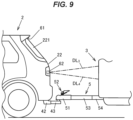
- FIG. 9 is an illustration showing the positions where the imaging device 61 and the radiation device 62 are disposed in the combination vehicle 1 according to the third example embodiment.
- the imaging device 61 and the radiation device 62 are mounted on the rear end of the towing vehicle 2 as in the first example embodiment, but the radiation device 62 irradiates the towed vehicle 3 instead of the towed-side connecting member 5.
- the radiation range of the marker light from the radiation device 62 is shown by two long dashed short dashed lines DL 3 , DL 4 .
- the imaging device 61 captures an image of a portion of the towed vehicle 3 that is irradiated with the marker light from the radiation device 62.
- the image analysis device 63 detects the hitch angle, the relative pitch angle, and the relative roll angle based on the size in the vehicle width direction, size in the up-down direction, and tilt of the marker light captured by the imaging device 61.
- the radiation device 62 since the radiation device 62 is mounted on the towing vehicle 2, the shape of the marker light that is captured by the imaging device 61 is less likely to change according to the hitch angle etc., compared to the second example embodiment. Therefore, in this example, the radiation device 62 irradiates the towed vehicle at such a position and in such a range that part of the marker light to be captured by the imaging device 61 disappears according to the magnitude of the hitch angle.
- FIGS. 10A, 10B, and 10C are illustrations of the towed vehicle 3 irradiated with the marker light from the radiation device 62, as viewed from the towing vehicle 2.
- FIG. 10A shows a state in which the hitch angle is zero.
- FIG. 10B shows a state in which the towed vehicle 3 is tilted to the right as viewed from the towing vehicle 2
- FIG. 10C shows a state in which the towed vehicle 3 is tilted to the left as viewed from the towing vehicle 2.
- the shape of a projected figure 625 projected by the marker light emitted from the radiation device 62 is an ellipse as in the second example embodiment.
- the image analysis device 63 can accurately obtain the hitch angle based on the amount of change in shape of the projected figure 625.
- the marker light emitted from the radiation device 62 is captured by the imaging device 61, and the image analysis device 63 detects the relative angle of the towed vehicle 3 with respect to the towing vehicle 2 by analyzing the captured image. Therefore, it is possible to detect the relative angle of the towed vehicle 3 with respect to the towing vehicle 2 without installing a marker such as a panel or a sheet on the towed vehicle 3.
- the above embodiment and example embodiments illustrate the case where the imaging device 61 is mounted on the towing vehicle 2 and captures an image of the towed vehicle 3.
- the imaging device 61 may be mounted on the towed vehicle 3 so that the imaging device 61 captures an image of the towing vehicle 2.
- the radiation device 62 emits the marker light from the towed vehicle 3 toward the towing vehicle 2.
- the above second and third example embodiments illustrate the case where the projected figures 624, 625 have an elliptical shape.
- the shapes of the projected figures 624, 625 are not limited to this, and the projected figures 624, 625 may have any shape such as a polygon or a polyline as long as they have predetermined lengths in the vehicle width direction and up-down direction of the towing vehicle 2.
Landscapes
- Engineering & Computer Science (AREA)
- Physics & Mathematics (AREA)
- General Physics & Mathematics (AREA)
- Transportation (AREA)
- Mechanical Engineering (AREA)
- Computer Vision & Pattern Recognition (AREA)
- Theoretical Computer Science (AREA)
- Geometry (AREA)
- Length Measuring Devices By Optical Means (AREA)
- Image Analysis (AREA)
Abstract
Description
- The present invention relates to relative angle detection devices for combination vehicles that are used in combination vehicles in which a towed vehicle is towed by a towing vehicle and that detect a relative angle of the towed vehicle with respect to the towing vehicle.
- A combination vehicle is known which is composed of a towed vehicle and a towing vehicle that are connected to each other and which can detect a hitch angle that is an angle of the towed vehicle with respect to the towing vehicle when the combination vehicle is viewed from above.
- A trailering assist system described in
PTL 1 captures an image of a target on a towed vehicle (trailer) by a camera disposed at the rear of a towing vehicle and detects a hitch angle by analyzing the captured image. A marker with a predetermined shape, such as an icon, provided on the front of the towed vehicle, is used as the target. For example,FIG. 1 ofPTL 1 shows a panel with a cross-shaped figure on it as a target. - PTL 1:
US patent No. 9950738 - Systems that detect a hitch angle based on an image of a target on a towed vehicle, such as the trailing assist system described in
PTL 1, require a panel, a sheet, etc. that serves as a target to be installed on the front of a towed vehicle, which increases the burden of installation of the systems. Installation of the target may affect the external appearance of the towed vehicle. - Therefore, an object of the present invention is to provide a relative angle detection device for a combination vehicle that can detect a relative angle of a towed vehicle with respect to a towing vehicle without installing on the towed vehicle a marker to be captured to detect the relative angle of the towed vehicle with respect to the towing vehicle. Solution to Problem
- In order to achieve the above object, the present invention provides a relative angle detection device for a combination vehicle. The relative angle detection device is used in the combination vehicle in which a towing vehicle and a towed vehicle are connected by a towing-side connecting member and a towed-side connecting member. The relative angle detection device includes: an imaging device that captures an image of one of the towing vehicle and the towed vehicle from the other; a radiation device that emits marker light to a position where the image is to be captured by the imaging device; and an image analysis device that analyzes the image captured by the imaging device to detect a relative angle of the towed vehicle with respect to the towing vehicle.
- According to the present invention, it is possible to detect the relative angle of the towed vehicle with respect to the towing vehicle without installing on the towed vehicle a marker to be captured to detect the relative angle of the towed vehicle with respect to the towing vehicle.
-
- (
FIG. 1A) FIG. 1A is a schematic diagram of a combination vehicle whose relative angle is to be detected according to an embodiment of the present invention, as viewed from above. - (
FIG. 1B) FIG. 1B is a schematic diagram of the combination vehicle as viewed from the left in the forward travel direction. - (
FIG. 1C) FIG. 1C is a schematic diagram of the combination vehicle as viewed from the rear. - (
FIG. 2A) FIG. 2A is a structure diagram showing an example of the structures of a towing-side connecting member and a towed-side connecting member. - (
FIG. 2B) FIG. 2B is a sectional view of the towing-side connecting member and the towed-side connecting member that are in a combined state. - (
FIG. 3) FIG. 3 is a block diagram showing an example of functional configurations of a relative angle detection device. - (
FIG. 4) FIG. 4 is a flowchart showing an example of the procedure of a process that is performed by the relative angle detection device. - (
FIG. 5A) FIG. 5A is an illustration showing the positions where an imaging device and a radiation device are disposed in a combination vehicle according to a first example embodiment. - (
FIG. 5B) FIG. 5B is an illustration showing the positions where the imaging device and the radiation device are disposed in the combination vehicle according to the first example embodiment. - (
FIG. 6A) FIG. 6A is an illustration showing an image captured by the imaging device according to the first example embodiment. - (
FIG. 6B) FIG. 6B is an illustration showing an image captured by the imaging device according to the first example embodiment. - (
FIG. 7) FIG. 7 is an illustration showing the positions where the imaging device and the radiation device are disposed in a combination vehicle according to a second example embodiment. - (
FIG. 8A) FIG. 8A is an illustration of a towed vehicle irradiated with marker light from a radiation device as viewed from a towing vehicle according to the second example embodiment. - (
FIG. 8B) FIG. 8B is an illustration of the towed vehicle irradiated with the marker light from the radiation device as viewed from the towing vehicle according to the second example embodiment. - (
FIG. 8C) FIG. 8C is an illustration of the towed vehicle irradiated with the marker light from the radiation device as viewed from the towing vehicle according to the second example embodiment. - (
FIG. 8D) FIG. 8D is an illustration of the towed vehicle irradiated with the marker light from the radiation device as viewed from the towing vehicle according to the second example embodiment. - (
FIG. 9) FIG. 9 is an illustration showing the positions where the imaging device and the radiation device are disposed in a combination vehicle according to a third example embodiment. - (
FIG. 10A) FIG. 10A is an illustration of the towed vehicle irradiated with the marker light from the radiation device as viewed from the towing vehicle according to the third example embodiment. - (
FIG. 10B) FIG. 10B is an illustration of the towed vehicle irradiated with the marker light from the radiation device as viewed from the towing vehicle according to the third example embodiment. - (
FIG. 10C) FIG. 10C is an illustration of the towed vehicle irradiated with the marker light from the radiation device as viewed from the towing vehicle according to the third example embodiment. - An embodiment of the present invention will be described with reference to the drawings. The embodiment and example embodiments that will be described below are shown as preferred specific examples for carrying out the present invention, and some portions specifically illustrate various technical matters that are technically preferable. However, the technical scope of the present invention is not limited to these specific forms.
-
FIGS. 1A, 1B, and 1C are schematic diagrams of acombination vehicle 1 with a relative angle detection device on which the relative angle detection device according to the embodiment of the present invention is mounted.FIG. 1A shows thecombination vehicle 1 as viewed from above, andFIG. 1B shows the left side of thecombination vehicle 1 in the forward travel direction.FIG. 1C shows thecombination vehicle 1 as viewed from the rear. InFIGS. 1A and 1B , each of acenter line 2a of a towingvehicle 2 in the front-rear direction of the towingvehicle 2 and a center line 3a of a towedvehicle 3 in the front-rear direction of the towedvehicle 3 is shown by a long dashed short dashed line. - The
combination vehicle 1 includes the towingvehicle 2 and the towedvehicle 3, and the towingvehicle 2 and the towedvehicle 3 are connected by a towing-side connecting member 4 and a towed-side connecting member 5.FIGS. 1A, 1B, and 1C show the case where the towedvehicle 3 is a box-shaped camper. However, the towed vehicle is not limited to this, and may be, for example, a boat trailer loaded with a boat. The towingvehicle 2 may be a manually driven vehicle in which a driver performs driving operations such as steering operations, or may be an autonomous vehicle in which part or all of driving operations are performed autonomously. -
FIG. 2A is a structure diagram showing an example of the structures of the towing-side connecting member 4 and the towed-side connecting member 5.FIG. 2B is a sectional view of the towing-side connecting member 4 and the towed-side connecting member 5 in a combined state. - The towing-
side connecting member 4 includes: ahitch cross member 41 disposed along the vehicle width direction of the towingvehicle 2; a pair ofhitch side members 42 fixed to both ends of thehitch cross member 41; aball mount 43 provided so as to protrude from the middle portion in the vehicle width direction of thehitch cross member 41 toward the rear side of the towingvehicle 2; ahitch pin 44 protruding upward from theball mount 43; and aspherical hitch ball 45 integral with the upper end of thehitch pin 44. Thehitch cross member 41 and the pair ofhitch side members 42 are disposed inside arear bumper 21 of the towingvehicle 2, and theball mount 43, thehitch pin 44, and thehitch ball 45 are exposed to the rear side from therear bumper 21. The pair ofhitch side members 42 is fixed to a body of the towingvehicle 2 by a plurality of bolts. - The towed-
side connecting member 5 includes: acoupler 51 that covers thehitch ball 45; alatch mechanism 52 that retains thecoupler 51 on thehitch ball 45; a rod-shapedtongue 53 with thecoupler 51 fixed to its distal end; and a pair of side beams 54 extending in a direction tilted with respect to the longitudinal direction of thetongue 53. Each of the side beams 54 has its one end connected to thetongue 53. A proximal end of thetongue 53 and the other end of each of the pair of side beams 54 are connected to a chassis of the towedvehicle 3. - As shown in
FIG. 2B , thecoupler 51 includes acup portion 511 that holds thehitch ball 45. Thelatch mechanism 52 includes: alever support 520; alever 521 that is rotated with respect to thelever support 520; alatch plate 522 that faces anupper surface 51a of thecoupler 51; alatch bar 523 that enters between theupper surface 51a of thecoupler 51 and thelatch plate 522 when thelever 521 is operated; alock plate 524 that receives thehitch ball 45 from below; acoil spring 525 that biases thelock plate 524 downward; and abolt 526 and anut 527 that connect thelatch plate 522 and thelock plate 524. - The
lock plate 524 is rotatable about asupport pin 512 that is provided horizontally to thecoupler 51. When thelever 521 is operated as shown by an arrow A inFIG. 2B , thelatch plate 522 is lifted upward with respect to thecoupler 51 by thelatch bar 523, and thelock plate 524 retains thehitch ball 45. Aninner surface 511a of thecup portion 511 of thecoupler 51 is a concave spherical surface having a curvature corresponding to the curvature of asurface 45a of thehitch ball 45. Thecoupler 51 is swingable in any direction about thehitch ball 45 due to sliding between theinner surface 511a of thecup portion 511 and thesurface 45a of thehitch ball 45. - In the
combination vehicle 1, the relative angle of the towedvehicle 3 with respect to the towingvehicle 2 changes variously. Particularly when thecombination vehicle 1 reverses with the towedvehicle 3 located on the front side in the direction of travel, the relative angle of the towedvehicle 3 with respect to the towingvehicle 2 serves as an important indicator when performing driving operations. For this reason, the relative angle detection device is used in thecombination vehicle 1. When the towingvehicle 2 is a manually driven vehicle (non-autonomous vehicle), an image showing the detection result from the relative angle detection device is displayed on a display installed inside a cabin of the towingvehicle 2, so that the driver is assisted in driving operations. When the towingvehicle 2 is an autonomous vehicle, the towingvehicle 2 is autonomously steered based on the detection result from the relative angle detection device. - The relative angle of the towed
vehicle 3 with respect to the towingvehicle 2 includes: a hitch angle that indicates tilt of the towedvehicle 3 in the horizontal direction with respect to the towingvehicle 2; a relative pitch angle that indicates tilt of the towedvehicle 3 in the up-down direction with respect to the towingvehicle 2; and a relative roll angle that is the difference between a roll angle of the towingvehicle 2 and a roll angle of the towedvehicle 3.FIG. 1A shows a hitch angle θh when the towedvehicle 3 is tilted to the left with respect to the towingvehicle 2.FIG. 1B shows a relative pitch angle θp when the towedvehicle 3 is tilted upward with respect to the towingvehicle 2.FIG. 1C shows a relative roll angle θr when the towedvehicle 3 is tilted clockwise with respect to the towingvehicle 2 as viewed from the rear of thecombination vehicle 1. - The relative angle detection device according to the embodiment can detect at least the hitch angle and the relative pitch angle out of the hitch angle, the relative pitch angle, and the relative roll angle. Next, the configuration, placement, and operation of the relative angle detection device will be described.
-
FIG. 3 is a block diagram showing functional configurations of a relativeangle detection device 6. The relativeangle detection device 6 includes: animaging device 61 that captures an image of one of the towingvehicle 2 and the towedvehicle 3 from the other; aradiation device 62 that emits marker light to a position where the image is to be captured by theimaging device 61; and animage analysis device 63 that analyzes the image captured by theimaging device 61 to detect the relative angle of the towedvehicle 3 relative to the towingvehicle 2. - The
radiation device 62 projects a figure with a predetermined shape by the marker light. The "figure" herein refers to a line segment of a predetermined length, a curve or a polyline, a closed curve such as a polygon or an ellipse, or one or more points. A laser beam with high linearity is used as the marker light. The color of the marker light is not particularly limited. For example, blue, red, or green visible laser light can be used as the marker light. In this case, a visible light camera is used as theimaging device 61. The marker light may be invisible light such as infrared light or ultraviolet light. In this case, a device that can capture light having the wavelength of the marker light, such as an infrared camera, is used as theimaging device 61. - The
imaging device 61 captures the figure projected by the marker light emitted from theradiation device 62, and detects the relative angle of the towedvehicle 3 with respect to the towingvehicle 2 from the shape of the captured figure. The detection result of the relative angle is sent to, for example, adisplay device 7 of the towingvehicle 2, and as shown inFIG. 3 , an image showing the detection result from the relativeangle detection device 6 is displayed on adisplay 71 inside the vehicle cabin.FIG. 3 shows a display example in which a bird's-eye view image 710 showing agraphic symbol 711 representing the towingvehicle 2 and agraphic symbol 712 representing the towedvehicle 3 in a tilted state according to the hitch angle detected by the relativeangle detection device 6 is displayed in afirst display area 71a of thedisplay 71. For example, an image captured by theimaging device 61 is displayed in asecond display area 71b of thedisplay 71. - The driver performs steering operations while taking the content displayed on the
display 71 into consideration. Thedisplay 71 may display an image showing a recommended direction of rotation of a steering wheel according to the hitch angle detected by the relativeangle detection device 6. When the towingvehicle 2 is an autonomous vehicle, the detection result from the relativeangle detection device 6 is output to anautonomous driving device 8. - The
radiation device 62 emits the marker light at least when thecombination vehicle 1 reverses. When the towingvehicle 2 is a manually driven vehicle, theradiation device 62 emits the marker light when, for example, a shift lever is shifted to reverse (R) range, and stops emitting the marker light when the shift lever is shifted from R range to a different range. Theradiation device 62 may be configured to emit the marker light according to a switch operation by the driver. Even when thecombination vehicle 1 moves forward, the state of the towedvehicle 3 may become unstable due to, for example, the slope of the road surface or a cross wind. In such a case, theradiation device 62 emits the marker light according to a switch operation by the driver, and the relativeangle detection device 6 detects the hitch angle, etc., so that the driver can be assisted in driving operations. When the towingvehicle 2 is an autonomous vehicle, theradiation device 62 starts and stops emitting the marker light according to a command signal from theautonomous driving device 8. -
FIG. 4 is a flowchart showing an example of the procedure of a process that is performed by the relativeangle detection device 6. The relativeangle detection device 6 repeatedly performs the process shown in this flowchart at a predetermined cycle of, for example, several milliseconds to several tens of milliseconds. - The relative
angle detection device 6 first determines whether to perform a process of detecting the relative angle of the towedvehicle 3 with respect to the towing vehicle 2 (step S1). As described above, this determination can be made according to, for example, a reverse driving operation or switch operation by the driver or a command signal from theautonomous driving device 8. When the result of this determination is Yes, theradiation device 62 emits the marker light (step S2), and theimaging device 61 captures the figure projected by the marker light (step S3). Information on the image captured by theimaging device 61 is sent to theimage analysis device 63. - The
image analysis device 63 analyzes the image captured by theimaging device 61 to detect the relative angle of the towedvehicle 3 with respect to the towing vehicle 2 (step S4). The analysis in step S4 can be performed by, for example, storing in advance the shape of the marker light that would be obtained when all of the hitch angle, the relative pitch angle, and the relative roll angle are zero as a reference shape, comparing the reference shape with the shape of the marker light in the image captured by theimaging device 61 to obtain the amount of change in shape, and converting this amount of change to the relative angle. The relative angle in the current cycle may be detected by referring to the detection result of the relative angle in the previous cycle. - On the other hand, when the result of the determination in step S1 is No, the
radiation device 62 stops emitting the marker light (step S5), and theimage analysis device 63 initializes the detection result of the relative angle (step S6). - Next, more specific embodiments, namely first to third example embodiments, of the relative
angle detection device 6 will be described in detail. -
FIGS. 5A and 5B are illustrations showing the positions where theimaging device 61 and theradiation device 62 are disposed in thecombination vehicle 1 according to a first example embodiment.FIG. 5A shows the rear side of the towingvehicle 2 as viewed from the towedvehicle 3.FIG. 5B shows the towing-side connecting member 4, the towed-side connecting member 5, part of the towingvehicle 2, and part of the towedvehicle 3, as viewed from the left side of the towingvehicle 2. - In the first example embodiment, the
imaging device 61 and theradiation device 62 are mounted on the rear end of the towingvehicle 2. More specifically, theimaging device 61 and theradiation device 62 are mounted on the outer side of abackdoor 22 of the towingvehicle 2. Theradiation device 62 is mounted at a position between alicense plate 23 and arear glass 221 of thebackdoor 22. Theimaging device 61 is disposed above theradiation device 62, and captures an image of the towedvehicle 3. In the example shown inFIG. 5A , theimaging device 61 is disposed directly above theradiation device 62. However, the position of theimaging device 61 may be shifted with respect to theradiation device 62 in the vehicle width direction of the towingvehicle 2. - In this example, the figure projected by the marker light emitted from the
radiation device 62 is a line segment of a predetermined length parallel to the vehicle width direction of the towingvehicle 2.FIG. 5A shows an angle of view VA indicating the imaging range of theimaging device 61 and a radiation range R of the marker light from theradiation device 62. InFIG. 5B , the direction of the marker light emitted from theradiation device 62 is shown by a long dashed short dashed line DL. The towed-side connecting member 5 and aroad surface 9 on both sides of the towed-side connecting member 5 in the vehicle width direction of the towingvehicle 2 are included in the radiation range of the marker light from theradiation device 62. In this example, theradiation device 62 irradiates thetongue 53 of the towed-side connecting member 5. However, the present invention is not limited to this, and theradiation device 62 may irradiate, for example, thecoupler 51. The angle of view VA of theimaging device 61 includes the entire radiation range R of theradiation device 62. Theroad surface 9 is, for example, the surface of a paved public road, but may be unpaved ground or the surface of a parking space in a parking lot. -
FIGS. 6A and 6B are illustrations each showing an image captured by theimaging device 61. In the following description, the "right side" and the "left side" refer to the right side and left side of the image captured by theimaging device 61.FIG. 6A shows a state in which the towingvehicle 2 and the towedvehicle 3 are aligned in a straight line with a hitch angle of zero.FIG. 6B shows a state in which the towedvehicle 3 is tilted to the right with respect to the towingvehicle 2. - The
imaging device 61 is disposed above theradiation device 62. Therefore, in the image captured by theimaging device 61, a firstirradiated portion 621 that indicates part of the marker light that is incident on the towed-side connecting member 5 appears above a secondirradiated portion 622 that indicates part of the marker light that is incident on theroad surface 9 on the left side of the towed-side connecting member 5 and a thirdirradiated portion 623 that indicates part of the marker light that is incident on theroad surface 9 on the right side of the towed-side connecting member 5. - In
FIGS. 6A and 6B , L0 indicates the total length of the first to thirdirradiated portions 621 to 623 in the left-right direction of the image captured by theimaging device 61, L1 indicates the length of the firstirradiated portion 621, L2 indicates the length of the secondirradiated portion 622, and L3 indicates the length of the thirdirradiated portion 623. More specifically, the length L1 is the length between the left end and right end of a portion of thetongue 53 that is irradiated by theradiation device 62. The length L2 is the length from the left end of theroad surface 9 irradiated by theradiation device 62 to the left end of the portion of thetongue 53 that is irradiated by theradiation device 62. The length L3 is the length from the right end of theroad surface 9 irradiated by theradiation device 62 to the right end of the portion of thetongue 53 that is irradiated by theradiation device 62. The length L0 is the length from the left end to the right end of theroad surface 9 irradiated by theradiation device 62. The lengths L1, L2, and L3 are index values that indicate the position in the vehicle width direction of the towed-side connecting member 5 in the radiation range of the marker light (length L0). - In the image captured by the
imaging device 61, when the midpoint of the length L0 is set as a reference position, the middle position in the left-right direction of thetongue 53 with respect to the reference position can be calculated by the arithmetic expression L0/2 - ((L2 + L1/2)/(L1 + L2 + L3)) × L0. Since the positional relationships between theimaging device 61 and theradiation device 62, thehitch ball 45, etc. are known, the hitch angle can be obtained by calculation based on the above arithmetic expression. Theimage analysis device 63 thus detects the hitch angle of thecombination vehicle 1 based on the position in the vehicle width direction of the towed-side connecting member 5 in the radiation range of the marker light. - In the image captured by the
imaging device 61, the distance D in the up-down direction between the firstirradiated portion 621 and the secondirradiated portion 622 and thirdirradiated portion 623 changes according to the relative pitch angle. Therefore, the relative pitch angle can be calculated based on this distance D. The distance D is an index value that indicates the difference in position in the front-rear direction of the towingvehicle 2 between the towed-side connecting member 5 and theroad surface 9 that are irradiated with the marker light. That is, theimage analysis device 63 detects the relative pitch angle of thecombination vehicle 1 based on the difference in position in the front-rear direction of the towingvehicle 2 between the towed-side connecting member 5 and theroad surface 9 that are irradiated with the marker light. - The
image analysis device 63 acquires information on the image from theimaging device 61 at a predetermined cycle, calculates the hitch angle and the relative pitch angle, and outputs the hitch angle and the relative pitch angle as the detection result. As the hitch angle increases, the marker light is also incident on the side surfaces in the left-right direction of thetongue 53, and therefore the length L1 of the firstirradiated portion 621 increases accordingly. Therefore, in the calculation for obtaining the hitch angle, it is necessary to correct the middle position in the left-right direction of thetongue 53 by, for example, using the hitch angle calculated in the previous cycle. This correction may be made by referring to map information that stores the relationship between the calculation result of the above arithmetic expression and the actual middle position in the left-right direction of thetongue 53. -
FIG. 7 is an illustration showing the positions where theimaging device 61 and theradiation device 62 are disposed in thecombination vehicle 1 according to the second example embodiment. In this example, theimaging device 61 is attached to the rear end of the towingvehicle 2 as in the first example embodiment, but theradiation device 62 is attached to the towed-side connecting member 5. Theradiation device 62 is fixed to thetongue 53 by abracket 55, and irradiates the front end of the towedvehicle 3 obliquely upward. InFIG. 7 , the radiation range of the marker light from theradiation device 62 is shown by two long dashed short dashed lines DL1, DL2. Theimaging device 61 is attached to a position between thelicense plate 23 and therear glass 221 of thebackdoor 22, and is also used as a camera for a rear monitor. -
FIGS. 8A, 8B ,8C, and 8D are illustrations of the towedvehicle 3 irradiated with the marker light from theradiation device 62, as viewed from the towingvehicle 2.FIG. 8A shows a state in which all of the hitch angle, the relative pitch angle, and the relative roll angle are zero.FIG. 8B shows a state when the towedvehicle 3 is tilted to the right as viewed from the towingvehicle 2.FIG. 8C shows a state when the towedvehicle 3 is tilted upward.FIG. 8D shows a state when the towedvehicle 3 rolls counterclockwise. - In this example, a projected figure 624 projected by the marker light emitted from the
radiation device 62 is an ellipse whose major axis is in the vehicle width direction of the towingvehicle 2 and whose minor axis is in the up-down direction. InFIG. 8A , D11 indicates the longer diameter of the projected figure 624, and D12 indicates the shorter diameter of the projected figure 624. The shape of the ellipse defined by the longer diameter D11 and the shorter diameter D12 is a reference shape of the projected figure 624. Theimage analysis device 63 stores the longer diameter D11 and the shorter diameter D12. - As shown in
FIG. 8B , when the towedvehicle 3 is tilted in the left-right direction with respect to the towingvehicle 2, the shape of the projected figure 624 that is captured by theimaging device 61 is distorted, and its longer diameter D21 becomes shorter than the longer diameter D11 of the projected figure 624 shown inFIG. 8A . The difference between the longer diameter D21 and the longer diameter D11 is the amount of distortion of the projected figure 624 due to the change in hitch angle. Theimage analysis device 63 converts this amount of distortion to a hitch angle. The hitch angle of thecombination vehicle 1 can thus be obtained. That is, in this example, theimage analysis device 63 detects the hitch angle based on the size of the marker light captured by theimaging device 61 in the vehicle width direction of the towingvehicle 2. - Whether the towed
vehicle 3 is tilted to the right or to the left with respect to the towingvehicle 2 can be determined based on, for example, the difference of the shapes of the right and left ends of the captured projected figure 624 from the reference shape of the projected figure 624. This is for the following reason. When the towedvehicle 3 is tilted to the right with respect to the towingvehicle 2, the right end of the captured projected figure 624 becomes larger than the reference shape while the left end of the captured projected figure 624 becomes smaller than the reference shape, according to the distance from theimaging device 61. The opposite occurs when the towedvehicle 3 is tilted to the left with respect to the towingvehicle 2. - As shown in
FIG. 8C , when the towedvehicle 3 is tilted in the up-down direction with respect to the towingvehicle 2, the shape of the projected figure 624 that is captured by theimaging device 61 is distorted, and its shorter diameter D32 becomes shorter than the shorter diameter D12 of the projected figure 624 shown inFIG. 8A . The difference between the shorter diameter D32 and the shorter diameter D12 is the amount of distortion of the projected figure 624 due to the change in relative pitch angle. Theimage analysis device 63 converts this amount of distortion to a relative pitch angle. The relative pitch angle of thecombination vehicle 1 can thus be obtained. That is, in this example, theimage analysis device 63 detects the relative hitch angle based on the size of the marker light captured by theimaging device 61 in the up-down direction of the towingvehicle 2. Whether the towedvehicle 3 is tilted in the upward direction or in the downward direction with respect to the towingvehicle 2 can be determined based on, for example, the difference of the shapes of the upper and lower ends of the captured projected figure 624 from the reference shape of the projected figure 624, as in the case of the tilt in the left-right direction described above. - As shown in
FIG. 8D , when the towedvehicle 3 rolls with respect to the towingvehicle 2, the shape of the projected figure 624 that is captured by theimaging device 61 is tilted with respect to the reference shape. InFIG. 8D , θ indicates the tilt angle of the major axis of the projected figure 624 with respect to the reference shape. This tilt angle θ is the amount of distortion of the projected figure 624 due to the relative roll angle, and theimage analysis device 63 can obtain the relative roll angle of thecombination vehicle 1 by converting this tilt angle θ to a relative roll angle. That is, in this example, theimage analysis device 63 detects the relative hitch angle based on the tilt of the towingvehicle 2 of the marker light captured by theimaging device 61. -
FIG. 9 is an illustration showing the positions where theimaging device 61 and theradiation device 62 are disposed in thecombination vehicle 1 according to the third example embodiment. In this example, theimaging device 61 and theradiation device 62 are mounted on the rear end of the towingvehicle 2 as in the first example embodiment, but theradiation device 62 irradiates the towedvehicle 3 instead of the towed-side connecting member 5. InFIG. 9 , the radiation range of the marker light from theradiation device 62 is shown by two long dashed short dashed lines DL3, DL4. - The
imaging device 61 captures an image of a portion of the towedvehicle 3 that is irradiated with the marker light from theradiation device 62. As in the second example embodiment, theimage analysis device 63 detects the hitch angle, the relative pitch angle, and the relative roll angle based on the size in the vehicle width direction, size in the up-down direction, and tilt of the marker light captured by theimaging device 61. - However, since the
radiation device 62 is mounted on the towingvehicle 2, the shape of the marker light that is captured by theimaging device 61 is less likely to change according to the hitch angle etc., compared to the second example embodiment. Therefore, in this example, theradiation device 62 irradiates the towed vehicle at such a position and in such a range that part of the marker light to be captured by theimaging device 61 disappears according to the magnitude of the hitch angle. -
FIGS. 10A, 10B, and 10C are illustrations of the towedvehicle 3 irradiated with the marker light from theradiation device 62, as viewed from the towingvehicle 2.FIG. 10A shows a state in which the hitch angle is zero.FIG. 10B shows a state in which the towedvehicle 3 is tilted to the right as viewed from the towingvehicle 2, andFIG. 10C shows a state in which the towedvehicle 3 is tilted to the left as viewed from the towingvehicle 2. The shape of a projected figure 625 projected by the marker light emitted from theradiation device 62 is an ellipse as in the second example embodiment. - As shown in
FIG. 10A , when the hitch angle is zero, the entire elliptical shape of the projected figure 625 is captured by theimaging device 61. However, when the towedvehicle 3 is tilted in the left-right direction with respect to the towingvehicle 2, a portion in the major axis direction of the projected figure 625 is located outside the front end of the towedvehicle 3 and disappears. The shape of the projected figure 625 thus changes, and the length of the projected figure 625 in the vehicle width direction of the towingvehicle 2 becomes shorter. Theimage analysis device 63 can accurately obtain the hitch angle based on the amount of change in shape of the projected figure 625. - According to the embodiment and the first to third example embodiments described above, the marker light emitted from the
radiation device 62 is captured by theimaging device 61, and theimage analysis device 63 detects the relative angle of the towedvehicle 3 with respect to the towingvehicle 2 by analyzing the captured image. Therefore, it is possible to detect the relative angle of the towedvehicle 3 with respect to the towingvehicle 2 without installing a marker such as a panel or a sheet on the towedvehicle 3. - Although the present invention is described above based on the embodiment and the example embodiments, the embodiment and the example embodiments are not intended to limit the invention according to the claims. It should be noted that not all combinations of the features described in the embodiments are essential as means for solving the problem of the invention. The present invention may be implemented in a modified form as appropriate by omitting part of the components or adding or replacing components without departing from the spirit and scope of the present invention. For example, the present invention can be implemented in the following modified forms.
- The above embodiment and example embodiments illustrate the case where the
imaging device 61 is mounted on the towingvehicle 2 and captures an image of the towedvehicle 3. Alternatively, theimaging device 61 may be mounted on the towedvehicle 3 so that theimaging device 61 captures an image of the towingvehicle 2. In this case, theradiation device 62 emits the marker light from the towedvehicle 3 toward the towingvehicle 2. - The above second and third example embodiments illustrate the case where the projected figures 624, 625 have an elliptical shape. However, the shapes of the projected figures 624, 625 are not limited to this, and the projected figures 624, 625 may have any shape such as a polygon or a polyline as long as they have predetermined lengths in the vehicle width direction and up-down direction of the towing
vehicle 2. -
- 1 COMBINATION VEHICLE
- 2 TOWING VEHICLE
- 3 TOWED VEHICLE
- 4 TOWING-SIDE CONNECTING MEMBER
- 5 TOWED-SIDE CONNECTING MEMBER
- 6 RELATIVE ANGLE DETECTION DEVICE
- 61 IMAGING DEVICE
- 62 RADIATION DEVICE
- 63 IMAGE ANALYSIS DEVICE
Claims (13)
- A relative angle detection device for a combination vehicle, the relative angle detection device being used in the combination vehicle in which a towing vehicle and a towed vehicle are connected by a towing-side connecting member and a towed-side connecting member, the relative angle detection device comprising:an imaging device that captures an image of one of the towing vehicle and the towed vehicle from the other;a radiation device that emits marker light to a position where the image is to be captured by the imaging device; andan image analysis device that analyzes the image captured by the imaging device to detect a relative angle of the towed vehicle with respect to the towing vehicle.
- The relative angle detection device for the combination vehicle according to claim 1, wherein the imaging device is mounted on the towing vehicle and captures an image of the towed vehicle.
- The relative angle detection device for the combination vehicle according to claim 1, wherein:the radiation device projects a figure with a predetermined shape by the marker light; andthe image analysis device detects the relative angle based on a shape of the figure that is captured.
- The relative angle detection device for the combination vehicle according to claim 1, wherein the relative angle that is detected by the image analysis device includes a hitch angle of the combination vehicle.
- The relative angle detection device for the combination vehicle according to claim 1, wherein the radiation device emits the marker light when the combination vehicle reverses.
- The relative angle detection device for the combination vehicle according to any one of claims 1 to 4, wherein:the imaging device and the radiation device are mounted on the towing vehicle; andthe towed-side connecting member and a road surface on both sides of the towed-side connecting member in a vehicle width direction of the towing vehicle are included in a radiation range of the marker light from the radiation device.
- The relative angle detection device for the combination vehicle according to claim 6, wherein the image analysis device detects a hitch angle of the combination vehicle based on a position in the vehicle width direction of the towed-side connecting member in the radiation range of the marker light.
- The relative angle detection device for the combination vehicle according to claim 6, wherein the image analysis device detects a pitch angle of the towed vehicle with respect to the towing vehicle based on a difference in position in a front-rear direction of the towing vehicle between the towed-side connecting member and the road surface that are irradiated with the marker light.
- The relative angle detection device for the combination vehicle according to any one of claims 1 to 5, wherein:the imaging device is mounted on the towing vehicle; andthe radiation device is mounted on the towed-side connecting member or the towed vehicle and irradiates the towed vehicle.
- The relative angle detection device for the combination vehicle according to claim 9, wherein the image analysis device detects a hitch angle of the combination vehicle based on a size of the marker light that is captured in a vehicle width direction of the towing vehicle.
- The relative angle detection device for the combination vehicle according to claim 9, wherein the image analysis device detects a pitch angle of the towed vehicle with respect to the towing vehicle based on a size of the marker light that is captured in an up-down direction of the towing vehicle.
- The relative angle detection device for the combination vehicle according to claim 9, wherein the image analysis device detects a roll angle of the towed vehicle with respect to the towing vehicle based on a tilt of the marker light that is captured.
- The relative angle detection device for the combination vehicle according to claim 9, wherein the radiation device irradiates the towed vehicle at such a position and in such a range that part of the marker light to be captured by the imaging device disappears according to a magnitude of a hitch angle of the combination vehicle.
Applications Claiming Priority (2)
| Application Number | Priority Date | Filing Date | Title |
|---|---|---|---|
| JP2022074934A JP7785607B2 (en) | 2022-04-28 | 2022-04-28 | Relative angle detection device for articulated vehicles |
| PCT/JP2023/008843 WO2023210172A1 (en) | 2022-04-28 | 2023-03-08 | Relative angle detection device for coupled vehicles |
Publications (2)
| Publication Number | Publication Date |
|---|---|
| EP4517664A1 true EP4517664A1 (en) | 2025-03-05 |
| EP4517664A4 EP4517664A4 (en) | 2025-08-27 |
Family
ID=88518463
Family Applications (1)
| Application Number | Title | Priority Date | Filing Date |
|---|---|---|---|
| EP23795919.2A Pending EP4517664A4 (en) | 2022-04-28 | 2023-03-08 | Relative angle detection device for coupled vehicles |
Country Status (5)
| Country | Link |
|---|---|
| US (1) | US20250292428A1 (en) |
| EP (1) | EP4517664A4 (en) |
| JP (1) | JP7785607B2 (en) |
| CN (1) | CN119096113A (en) |
| WO (1) | WO2023210172A1 (en) |
Families Citing this family (1)
| Publication number | Priority date | Publication date | Assignee | Title |
|---|---|---|---|---|
| JP2024166869A (en) * | 2023-05-19 | 2024-11-29 | アルプスアルパイン株式会社 | Hitch angle calculation system |
Family Cites Families (12)
| Publication number | Priority date | Publication date | Assignee | Title |
|---|---|---|---|---|
| JP3643076B2 (en) * | 2001-11-15 | 2005-04-27 | 日野自動車株式会社 | Connecting angle detector |
| DE102004022113A1 (en) * | 2004-05-05 | 2005-11-24 | Robert Bosch Gmbh | Monitoring a car trailer with a reversing camera |
| JP2008217267A (en) * | 2007-03-01 | 2008-09-18 | Denso Corp | Road shape recognition device |
| JP2009276166A (en) * | 2008-05-14 | 2009-11-26 | Panasonic Corp | Mobile apparatus and its position recognition method |
| US20100212170A1 (en) * | 2009-02-26 | 2010-08-26 | Shawn Marsee | Laser Line Convergence Vehicle Alignment System |
| US9085261B2 (en) | 2011-01-26 | 2015-07-21 | Magna Electronics Inc. | Rear vision system with trailer angle detection |
| DE102012015435A1 (en) * | 2012-08-03 | 2014-02-06 | Volkswagen Aktiengesellschaft | Method and device for maneuvering a trailer |
| US9464887B2 (en) * | 2013-11-21 | 2016-10-11 | Ford Global Technologies, Llc | Illuminated hitch angle detection component |
| KR20160041445A (en) * | 2014-10-07 | 2016-04-18 | 현대모비스 주식회사 | Trailer Track Estimation Method and System by Image Recognition |
| DE102019106275A1 (en) * | 2019-03-12 | 2020-09-17 | Wabco Gmbh | Acquisition system and method for determining an articulation angle between two sub-vehicles of a vehicle combination and vehicle combination |
| US11783506B2 (en) * | 2020-12-22 | 2023-10-10 | Continental Autonomous Mobility US, LLC | Method and device for detecting a trailer angle |
| KR102248504B1 (en) * | 2021-03-09 | 2021-05-06 | 시설물안전연구원 주식회사 | Apparatus for measuring a slope of object and control method thereof |
-
2022
- 2022-04-28 JP JP2022074934A patent/JP7785607B2/en active Active
-
2023
- 2023-03-08 EP EP23795919.2A patent/EP4517664A4/en active Pending
- 2023-03-08 CN CN202380036208.6A patent/CN119096113A/en active Pending
- 2023-03-08 US US18/860,223 patent/US20250292428A1/en active Pending
- 2023-03-08 WO PCT/JP2023/008843 patent/WO2023210172A1/en not_active Ceased
Also Published As
| Publication number | Publication date |
|---|---|
| JP7785607B2 (en) | 2025-12-15 |
| JP2023163794A (en) | 2023-11-10 |
| US20250292428A1 (en) | 2025-09-18 |
| CN119096113A (en) | 2024-12-06 |
| WO2023210172A1 (en) | 2023-11-02 |
| EP4517664A4 (en) | 2025-08-27 |
Similar Documents
| Publication | Publication Date | Title |
|---|---|---|
| US11872939B2 (en) | Vehicular trailer angle detection system | |
| JP3470947B2 (en) | Connection alignment warning system | |
| US7904222B2 (en) | Trailer articulation angle estimation | |
| US20140330487A1 (en) | System for Controlling the Adjustment of a Side Rearview Device | |
| EP1593552A1 (en) | System and method for monitoring a car trailer | |
| US20250292428A1 (en) | Relative angle detection device for combination vehicle | |
| US20240273698A1 (en) | Improved method and system for monitoring wheels | |
| US20210170821A1 (en) | Method and device for ascertaining a relative angle between two vehicles | |
| CA2411035C (en) | Towing carriage | |
| EP4517665A1 (en) | Relative angle detection device for coupled vehicle | |
| US20250121775A1 (en) | Camera Wing System, Vehicle Therewith and Method to Operate the Same | |
| CN215622333U (en) | Can independently detect album truck of trailing contained angle | |
| US11866033B2 (en) | Method for estimating an effective length of a first vehicle segment of a vehicle combination | |
| US11952037B2 (en) | Method and apparatus in a motor vehicle for reversing multiple trailers | |
| US12600292B2 (en) | Sensor and indicator light mounting structure, and cargo handling vehicle | |
| DK2786347T3 (en) | A system for controlling the option of a sidebakspejlsanordning | |
| CN118991309A (en) | Traction angle detection system | |
| EP2127999A2 (en) | System for assisting a driver while manoeuvring a truck towards a loading or unloading bay |
Legal Events
| Date | Code | Title | Description |
|---|---|---|---|
| STAA | Information on the status of an ep patent application or granted ep patent |
Free format text: STATUS: THE INTERNATIONAL PUBLICATION HAS BEEN MADE |
|
| PUAI | Public reference made under article 153(3) epc to a published international application that has entered the european phase |
Free format text: ORIGINAL CODE: 0009012 |
|
| STAA | Information on the status of an ep patent application or granted ep patent |
Free format text: STATUS: REQUEST FOR EXAMINATION WAS MADE |
|
| 17P | Request for examination filed |
Effective date: 20241120 |
|
| AK | Designated contracting states |
Kind code of ref document: A1 Designated state(s): AL AT BE BG CH CY CZ DE DK EE ES FI FR GB GR HR HU IE IS IT LI LT LU LV MC ME MK MT NL NO PL PT RO RS SE SI SK SM TR |
|
| DAV | Request for validation of the european patent (deleted) | ||
| DAX | Request for extension of the european patent (deleted) | ||
| A4 | Supplementary search report drawn up and despatched |
Effective date: 20250728 |
|
| RIC1 | Information provided on ipc code assigned before grant |
Ipc: G06T 7/60 20170101AFI20250722BHEP Ipc: G01B 11/26 20060101ALI20250722BHEP Ipc: B60D 1/06 20060101ALI20250722BHEP Ipc: B60D 1/24 20060101ALI20250722BHEP Ipc: B60D 1/62 20060101ALI20250722BHEP |