EP4517434A1 - Image forming apparatus - Google Patents
Image forming apparatus Download PDFInfo
- Publication number
- EP4517434A1 EP4517434A1 EP24191162.7A EP24191162A EP4517434A1 EP 4517434 A1 EP4517434 A1 EP 4517434A1 EP 24191162 A EP24191162 A EP 24191162A EP 4517434 A1 EP4517434 A1 EP 4517434A1
- Authority
- EP
- European Patent Office
- Prior art keywords
- transfer
- secondary transfer
- image forming
- forming apparatus
- transfer unit
- Prior art date
- Legal status (The legal status is an assumption and is not a legal conclusion. Google has not performed a legal analysis and makes no representation as to the accuracy of the status listed.)
- Pending
Links
Images


Classifications
-
- G—PHYSICS
- G03—PHOTOGRAPHY; CINEMATOGRAPHY; ANALOGOUS TECHNIQUES USING WAVES OTHER THAN OPTICAL WAVES; ELECTROGRAPHY; HOLOGRAPHY
- G03G—ELECTROGRAPHY; ELECTROPHOTOGRAPHY; MAGNETOGRAPHY
- G03G21/00—Arrangements not provided for by groups G03G13/00 - G03G19/00, e.g. cleaning, elimination of residual charge
- G03G21/16—Mechanical means for facilitating the maintenance of the apparatus, e.g. modular arrangements
- G03G21/1642—Mechanical means for facilitating the maintenance of the apparatus, e.g. modular arrangements for connecting the different parts of the apparatus
- G03G21/1647—Mechanical connection means
-
- G—PHYSICS
- G03—PHOTOGRAPHY; CINEMATOGRAPHY; ANALOGOUS TECHNIQUES USING WAVES OTHER THAN OPTICAL WAVES; ELECTROGRAPHY; HOLOGRAPHY
- G03G—ELECTROGRAPHY; ELECTROPHOTOGRAPHY; MAGNETOGRAPHY
- G03G15/00—Apparatus for electrographic processes using a charge pattern
- G03G15/14—Apparatus for electrographic processes using a charge pattern for transferring a pattern to a second base
- G03G15/16—Apparatus for electrographic processes using a charge pattern for transferring a pattern to a second base of a toner pattern, e.g. a powder pattern, e.g. magnetic transfer
- G03G15/1605—Apparatus for electrographic processes using a charge pattern for transferring a pattern to a second base of a toner pattern, e.g. a powder pattern, e.g. magnetic transfer using at least one intermediate support
-
- G—PHYSICS
- G03—PHOTOGRAPHY; CINEMATOGRAPHY; ANALOGOUS TECHNIQUES USING WAVES OTHER THAN OPTICAL WAVES; ELECTROGRAPHY; HOLOGRAPHY
- G03G—ELECTROGRAPHY; ELECTROPHOTOGRAPHY; MAGNETOGRAPHY
- G03G15/00—Apparatus for electrographic processes using a charge pattern
- G03G15/14—Apparatus for electrographic processes using a charge pattern for transferring a pattern to a second base
- G03G15/16—Apparatus for electrographic processes using a charge pattern for transferring a pattern to a second base of a toner pattern, e.g. a powder pattern, e.g. magnetic transfer
- G03G15/1605—Apparatus for electrographic processes using a charge pattern for transferring a pattern to a second base of a toner pattern, e.g. a powder pattern, e.g. magnetic transfer using at least one intermediate support
- G03G15/161—Apparatus for electrographic processes using a charge pattern for transferring a pattern to a second base of a toner pattern, e.g. a powder pattern, e.g. magnetic transfer using at least one intermediate support with means for handling the intermediate support, e.g. heating, cleaning, coating with a transfer agent
-
- G—PHYSICS
- G03—PHOTOGRAPHY; CINEMATOGRAPHY; ANALOGOUS TECHNIQUES USING WAVES OTHER THAN OPTICAL WAVES; ELECTROGRAPHY; HOLOGRAPHY
- G03G—ELECTROGRAPHY; ELECTROPHOTOGRAPHY; MAGNETOGRAPHY
- G03G15/00—Apparatus for electrographic processes using a charge pattern
- G03G15/14—Apparatus for electrographic processes using a charge pattern for transferring a pattern to a second base
- G03G15/16—Apparatus for electrographic processes using a charge pattern for transferring a pattern to a second base of a toner pattern, e.g. a powder pattern, e.g. magnetic transfer
- G03G15/1665—Apparatus for electrographic processes using a charge pattern for transferring a pattern to a second base of a toner pattern, e.g. a powder pattern, e.g. magnetic transfer by introducing the second base in the nip formed by the recording member and at least one transfer member, e.g. in combination with bias or heat
- G03G15/167—Apparatus for electrographic processes using a charge pattern for transferring a pattern to a second base of a toner pattern, e.g. a powder pattern, e.g. magnetic transfer by introducing the second base in the nip formed by the recording member and at least one transfer member, e.g. in combination with bias or heat at least one of the recording member or the transfer member being rotatable during the transfer
- G03G15/1675—Apparatus for electrographic processes using a charge pattern for transferring a pattern to a second base of a toner pattern, e.g. a powder pattern, e.g. magnetic transfer by introducing the second base in the nip formed by the recording member and at least one transfer member, e.g. in combination with bias or heat at least one of the recording member or the transfer member being rotatable during the transfer with means for controlling the bias applied in the transfer nip
-
- G—PHYSICS
- G03—PHOTOGRAPHY; CINEMATOGRAPHY; ANALOGOUS TECHNIQUES USING WAVES OTHER THAN OPTICAL WAVES; ELECTROGRAPHY; HOLOGRAPHY
- G03G—ELECTROGRAPHY; ELECTROPHOTOGRAPHY; MAGNETOGRAPHY
- G03G15/00—Apparatus for electrographic processes using a charge pattern
- G03G15/14—Apparatus for electrographic processes using a charge pattern for transferring a pattern to a second base
- G03G15/16—Apparatus for electrographic processes using a charge pattern for transferring a pattern to a second base of a toner pattern, e.g. a powder pattern, e.g. magnetic transfer
- G03G15/1665—Apparatus for electrographic processes using a charge pattern for transferring a pattern to a second base of a toner pattern, e.g. a powder pattern, e.g. magnetic transfer by introducing the second base in the nip formed by the recording member and at least one transfer member, e.g. in combination with bias or heat
- G03G15/167—Apparatus for electrographic processes using a charge pattern for transferring a pattern to a second base of a toner pattern, e.g. a powder pattern, e.g. magnetic transfer by introducing the second base in the nip formed by the recording member and at least one transfer member, e.g. in combination with bias or heat at least one of the recording member or the transfer member being rotatable during the transfer
- G03G15/1685—Structure, details of the transfer member, e.g. chemical composition
-
- G—PHYSICS
- G03—PHOTOGRAPHY; CINEMATOGRAPHY; ANALOGOUS TECHNIQUES USING WAVES OTHER THAN OPTICAL WAVES; ELECTROGRAPHY; HOLOGRAPHY
- G03G—ELECTROGRAPHY; ELECTROPHOTOGRAPHY; MAGNETOGRAPHY
- G03G15/00—Apparatus for electrographic processes using a charge pattern
- G03G15/65—Apparatus which relate to the handling of copy material
- G03G15/6555—Handling of sheet copy material taking place in a specific part of the copy material feeding path
- G03G15/657—Feeding path after the transfer point and up to the fixing point, e.g. guides and feeding means for handling copy material carrying an unfused toner image
-
- G—PHYSICS
- G03—PHOTOGRAPHY; CINEMATOGRAPHY; ANALOGOUS TECHNIQUES USING WAVES OTHER THAN OPTICAL WAVES; ELECTROGRAPHY; HOLOGRAPHY
- G03G—ELECTROGRAPHY; ELECTROPHOTOGRAPHY; MAGNETOGRAPHY
- G03G15/00—Apparatus for electrographic processes using a charge pattern
- G03G15/80—Details relating to power supplies, circuits boards, electrical connections
-
- G—PHYSICS
- G03—PHOTOGRAPHY; CINEMATOGRAPHY; ANALOGOUS TECHNIQUES USING WAVES OTHER THAN OPTICAL WAVES; ELECTROGRAPHY; HOLOGRAPHY
- G03G—ELECTROGRAPHY; ELECTROPHOTOGRAPHY; MAGNETOGRAPHY
- G03G21/00—Arrangements not provided for by groups G03G13/00 - G03G19/00, e.g. cleaning, elimination of residual charge
- G03G21/06—Eliminating residual charges from a reusable imaging member
-
- G—PHYSICS
- G03—PHOTOGRAPHY; CINEMATOGRAPHY; ANALOGOUS TECHNIQUES USING WAVES OTHER THAN OPTICAL WAVES; ELECTROGRAPHY; HOLOGRAPHY
- G03G—ELECTROGRAPHY; ELECTROPHOTOGRAPHY; MAGNETOGRAPHY
- G03G21/00—Arrangements not provided for by groups G03G13/00 - G03G19/00, e.g. cleaning, elimination of residual charge
- G03G21/16—Mechanical means for facilitating the maintenance of the apparatus, e.g. modular arrangements
- G03G21/1642—Mechanical means for facilitating the maintenance of the apparatus, e.g. modular arrangements for connecting the different parts of the apparatus
- G03G21/1652—Electrical connection means
-
- G—PHYSICS
- G03—PHOTOGRAPHY; CINEMATOGRAPHY; ANALOGOUS TECHNIQUES USING WAVES OTHER THAN OPTICAL WAVES; ELECTROGRAPHY; HOLOGRAPHY
- G03G—ELECTROGRAPHY; ELECTROPHOTOGRAPHY; MAGNETOGRAPHY
- G03G21/00—Arrangements not provided for by groups G03G13/00 - G03G19/00, e.g. cleaning, elimination of residual charge
- G03G21/16—Mechanical means for facilitating the maintenance of the apparatus, e.g. modular arrangements
- G03G21/1661—Mechanical means for facilitating the maintenance of the apparatus, e.g. modular arrangements means for handling parts of the apparatus in the apparatus
- G03G21/168—Mechanical means for facilitating the maintenance of the apparatus, e.g. modular arrangements means for handling parts of the apparatus in the apparatus for the transfer unit
-
- G—PHYSICS
- G03—PHOTOGRAPHY; CINEMATOGRAPHY; ANALOGOUS TECHNIQUES USING WAVES OTHER THAN OPTICAL WAVES; ELECTROGRAPHY; HOLOGRAPHY
- G03G—ELECTROGRAPHY; ELECTROPHOTOGRAPHY; MAGNETOGRAPHY
- G03G2215/00—Apparatus for electrophotographic processes
- G03G2215/16—Transferring device, details
- G03G2215/1604—Main transfer electrode
- G03G2215/1614—Transfer roll
Definitions
- Embodiments of the present disclosure relate to an image forming apparatus such as a copying machine, a printer, a facsimile machine, or a multifunction peripheral thereof, or a printing machine, in which a transferor such as a secondary transfer roller is disposed.
- a transfer unit for holding a secondary transfer roller is urged by an urging member to contact the transfer unit to a positioning portion of a body of an image forming apparatus, such that the transfer unit is positioned with respect to the body of the image forming apparatus (see, e.g., Japanese Unexamined Patent Application Publication No. 2019-133008 ).
- a power supply terminal disposed on a body cover is contacted to a power-supplied member such as a secondary transfer roller in conjunction with an operation of closing the body cover, such that power supply from a power supply to the power-supplied member is enabled (see, e.g., Japanese Patent No. 4368663 ).
- a member for positioning a transfer unit holding a transfer member in a body of the image forming apparatus and a member for supplying power to the transfer member are separately disposed. Such a configuration may cause a complicated structure and high costs in the image forming apparatus.
- An object of the present disclosure is to provide an image forming apparatus in which positioning of a transfer unit holding a transfer member with respect to a body of an image forming apparatus and supplying power to the transfer member. can be easily performed.
- an image forming apparatus includes a body, a transfer member, a transfer unit, a power supply, and an urging member.
- the transfer member transfers an image onto a transfer medium.
- the transfer unit is supported to rotate around a support shaft with respect to the body and holds the transfer member.
- the power supply outputs a transfer bias to be applied to the transfer member.
- the urging member urges the transfer unit in a direction in which the transfer unit contacts a positioning portion of the body and is a part or all of a power supply path of the transfer bias from the power supply to the transfer member.
- an image forming apparatus can be provided in which positioning of a transfer unit holding a transfer member with respect to a body of an image forming apparatus and supplying power to the transfer member are easily performed.
- the image forming apparatus 1 is a tandem-type color printer.
- Four toner bottles 102Y, 102M, 102C, and 102K corresponding to respective colors (yellow, magenta, cyan, and black) are detachably (replaceably) attached to a bottle housing 101 located above a body of the image forming apparatus 1.
- An intermediate transfer unit 85 is disposed below the bottle housing 101.
- Image forming devices 4Y, 4M, 4C, and 4K corresponding to the respective colors (yellow, magenta, cyan, and black) are arranged in parallel to face an intermediate transfer belt 78 (an intermediate transferor) of the intermediate transfer unit 85.
- the image forming apparatus 1 includes a sheet feeder 12 (a sheet tray) in a lower portion of the body of the image forming apparatus 1.
- the sheet feeder 12 stores a stack of multiple sheets P such as sheets of paper stacked on one on another.
- an opening-and-closing cover 50 for exposing the inside of the image forming apparatus 1 for example, conveyance paths K0 and K 1 of the sheet P, and a fixing device 20
- an opening-and-closing cover 50 for exposing the inside of the image forming apparatus 1 for example, conveyance paths K0 and K 1 of the sheet P, and a fixing device 20
- the image forming devices 4Y, 4M, 4C, and 4K include photoconductor drums 5Y, 5M, 5C, and 5K, respectively.
- Each of the photoconductor drums 5Y, 5M, 5C, and 5K is surrounded by, for example, a charger 75, a developing device 76, a cleaner 77, and a charge eliminating device.
- Image forming processes including a charging process, an exposure process, a developing process, a primary transfer process, and a cleaning process are performed on each of the photoconductor drums 5Y, 5M, 5C, and 5K to form yellow, magenta, cyan, and black toner images on the photoconductor drums 5Y, 5M, 5C, and 5K, respectively.
- a main motor drives to rotate the photoconductor drums 5Y, 5M, 5C, and 5K counterclockwise in FIG. 1 .
- the charger 75 disposed opposite each of the photoconductor drums 5Y, 5M, 5C, and 5K uniformly charges the outer circumferential surface thereof (a charging process). After the charging process, the charged outer circumferential surface of each of the photoconductor drums 5Y, 5M, 5C, and 5K reaches an irradiation position at which an exposure device 3 (in other words, a writing device) irradiates and scans the photoconductor drums 5Y, 5M, 5C, and 5K with laser beams.
- an exposure device 3 in other words, a writing device
- the photoconductor drums 5Y, 5M, 5C, and 5K are irradiated and scanned with the laser beams L forms electrostatic latent images according to yellow, magenta, cyan, and black image data (an exposure process).
- each of the photoconductor drums 5Y, 5M, 5C, and 5K reaches a developing position at which the developing device 76 is disposed opposite each of the photoconductor drums 5Y, 5M, 5C, and 5K, and the developing device 76 develops the electrostatic latent image formed on the respective photoconductor drums 5Y, 5M, 5C, and 5K, thus forming yellow, magenta, cyan, and black toner images on the photoconductor drums 5Y, 5M, 5C, and 5K (a developing process).
- the yellow, magenta, cyan, and black toner images formed on the photoconductor drums 5Y, 5M, 5C, and 5K reach primary transfer nips formed between the photoconductor drums 5Y, 5M, 5C, and 5K and the intermediate transfer belt 78 by four primary transfer bias rollers 79Y, 79M, 79C, and 79K pressed against the four photoconductor drums 5Y, 5M, 5C, and 5K via the intermediate transfer belt 78, respectively, and the yellow, magenta, cyan, and black toner images are primarily transferred onto the intermediate transfer belt 78 (a primary transfer process). After the primary transfer process, residual toner (untransferred toner) onto the intermediate transfer belt 78 slightly remains on the photoconductor drums 5Y, 5M, 5C, and 5K.
- the residual toner (untransferred toner) on each of the photoconductor drums 5Y, 5M, 5C, and 5K reaches a cleaning position at which the cleaner 77 is disposed opposite each of the photoconductor drums 5Y, 5M, 5C, and 5K, and a cleaning blade of the cleaner 77 mechanically collects the residual toner from each of the photoconductor drums 5Y, 5M, 5C, and 5K (a cleaning process).
- each of the photoconductor drums 5Y, 5M, 5C, and 5K reaches a charge removal position at which the charge removing device is disposed opposite a corresponding one of the photoconductor drums 5Y, 5M, 5C, and 5K, and the charge removing device eliminates residual potential from each of the photoconductor drums 5Y, 5M, 5C, and 5K.
- a series of image forming processes performed on the photoconductor drums 5Y, 5M, 5C, and 5K is finished.
- the yellow, magenta, cyan, and black toner images formed on the photoconductor drums 5Y, 5M, 5C, and 5K in the developing process are primarily transferred onto an outer circumferential surface of the intermediate transfer belt 78 (intermediate transferor) such that the yellow, magenta, cyan, and black toner images are superimposed on the intermediate transfer belt 78.
- a color toner image is formed on the surface of the intermediate transfer belt 78.
- the intermediate transfer unit 85 includes the intermediate transfer belt 78 as an intermediate transferor, the four primary transfer bias rollers 79Y, 79M, 79C, and 79K, a secondary-transfer backup roller 82, a cleaning backup roller 83, a tension roller 84, and an intermediate transfer cleaner 80.
- the intermediate transfer belt 78 is extended and supported by the three rollers, that is, the secondary-transfer backup roller 82, the cleaning backup roller 83, and a tension roller 84.
- One of the three rollers, that is, the secondary-transfer backup roller 82 is coupled to the main motor to drive and rotate the intermediate transfer belt 78 in a rotation direction indicated by an arrow in FIG. 1 .
- the four primary transfer bias rollers 79Y, 79M, 79C, and 79K are pressed against the corresponding photoconductor drums 5Y, 5M, 5C, and 5K, respectively, via the intermediate transfer belt 78 to form primary transfer nips.
- Each of the primary transfer bias rollers 79Y, 79M, 79C, and 79K is applied with a primary transfer bias having a polarity opposite a polarity of electric charge of toner.
- the intermediate transfer belt 78 moves in the direction indicated by the arrow in FIG. 1 and sequentially passes through the primary transfer nips of the primary transfer bias rollers 79Y, 79M, 79C, and 79K.
- the toner images formed on the respective photoconductor drums 5Y, 5M, 5C, and 5K are primarily transferred onto the intermediate transfer belt 78 while being superimposed one atop another to form a composite color toner image on the intermediate transfer belt 78 (a primary transfer process).
- the intermediate transfer belt 78 to which the superimposed toner images of yellow, magenta, cyan, and black have been transferred reaches a position opposite (facing) a secondary transfer roller 89 as a transferor.
- the secondary-transfer backup roller 82 and the secondary transfer roller 89 (transferor) nip the intermediate transfer belt 78 therebetween to form a secondary transfer nip.
- the toner images of four colors formed on the intermediate transfer belt 78 are transferred (secondarily transferred) onto the sheet P conveyed to the position of the secondary transfer nip (a secondary transfer process).
- untransferred toner that is not transferred onto the sheet P remains on the surface of the intermediate transfer belt 78.
- the surface of the intermediate transfer belt 78 then reaches a position opposite the intermediate transfer cleaner 80. At this position, the intermediate transfer cleaner 80 collects the untransferred toner from the intermediate transfer belt 78. Thus, a series of transfer processes performed on the intermediate transfer belt 78 is completed.
- the sheet P is conveyed from the sheet feeder 12 disposed in the lower portion of the body of the image forming apparatus 1 to the secondary transfer nip via the conveyance path K0.
- the sheet feeder 12 contains a stack of multiple sheets P (transfer media) such as sheets of paper stacked on one on another.
- a sheet feed roller 31 is rotated counterclockwise in FIG. 1 , the uppermost sheet P nipped between the sheet feed roller 31 and a friction pad 32 is fed toward between the rollers of a registration roller pair 33 (timing roller pair) while the sheet P is guided by guide plates forming the conveyance path K0.
- the sheet P conveyed to the registration roller pair 33 serving as a timing roller pair temporarily stops at a position of a roller nip (nip portion) of the registration roller pair 33 that stops rotating.
- Rotation of the registration roller pair 33 is timed to convey the sheet P toward the secondary transfer nip such that the sheet P as a transfer medium meets the color toner image on the intermediate transfer belt 78 at the secondary transfer nip.
- the desired color toner image is transferred onto the sheet P.
- the sheet P, onto which the color toner image is transferred at the secondary transfer nip is conveyed to a position of a fixing device 20 via a conveyance path.
- a fixing nip formed by a fixing belt 21 and a pressure roller 22 pressing each other the toner image transferred onto the surface of the sheet P is fixed onto the sheet P by heat and pressure from a fixing belt (a fixing process).
- the sheet P bearing the fixed toner image is conveyed through the conveyance path K1 and ejected by a sheet ejection roller pair 40 to the outside of the image forming apparatus 1.
- the sheets P ejected one by one by the sheet ejection roller pair 40 to the outside of the image forming apparatus 1 are sequentially stacked as output images on a stacker 100.
- a series of image forming processes performed by the image forming apparatus 1 is completed.
- the opening-and-closing cover 50 for opening and closing the inside of the image forming apparatus 1 is disposed on the left of the image forming apparatus 1 according to the present embodiment.
- the opening-and-closing cover 50 is rotatable around a support shaft 50a in order to open and close the inside of the image forming apparatus 1.
- the opening-and-closing cover 50 holds a secondary transfer unit 60 (which holds a secondary transfer roller 89) to be described later. Accordingly, the secondary transfer unit 60 is rotated around the support shaft 50a together with the opening-and-closing cover 50 in conjunction with the opening and closing operation of the opening-and-closing cover 50.
- the opening-and-closing cover 50 in an open state as illustrated in FIG. 2B is rotated clockwise in FIG. 2B around the support shaft 50a together with the secondary transfer unit 60, the opening-and-closing cover 50 turns to a closed state as illustrated FIGS. 2A and 3 , and then the secondary transfer roller 89 contacts the intermediate transfer belt 78 to form the secondary transfer nip.
- the image forming apparatus 1 includes the secondary transfer roller 89 as a transfer member for transferring an image onto the sheet P as a transfer medium.
- the secondary transfer roller 89 as a transfer member is a roller that contacts the intermediate transfer belt 78 as an intermediate transferor to form a secondary transfer nip, and secondarily transfers an image primarily transferred onto the intermediate transfer belt 78 onto the sheet P as a transfer medium conveyed to the secondary transfer nip.
- the secondary transfer roller 89 includes a shaft 89a (see FIG. 3 ) made of a conductive material such as stainless steel. An elastic layer is formed (coated) on the shaft 89a.
- the elastic layer of the secondary transfer roller 89 is a solid rubber or a foam-sponge rubber made of, e.g., polyurethane, ethylene-propylene-diene monomer (EPDM), or silicone having a conductive filler such as carbon dispersed or containing an ionic conductive material.
- EPDM ethylene-propylene-diene monomer
- silicone having a conductive filler such as carbon dispersed or containing an ionic conductive material.
- the image forming apparatus 1 includes a power supply 110 for outputting a transfer bias (a secondary transfer bias) to be applied to the secondary transfer roller 89 (transfer member).
- the power supply 110 applies the secondary transfer bias having a polarity different from the polarity of the toner to the secondary transfer roller 89 to form a secondary-transfer electric field at the position of the secondary transfer nip, the toner borne on the outer circumferential surface (toner bearing surface) of the intermediate transfer belt 78 is electrostatically moved toward the secondary transfer roller 89.
- the secondary transfer bias may be a direct-current voltage, or a direct-current voltage on which an alternating-current voltage is superimposed.
- the image forming apparatus 1 includes the secondary transfer unit 60 as a transfer unit that holds the secondary transfer roller 89 (transfer member).
- the secondary transfer unit 60 (transfer unit) is supported to be rotatable around the support shaft 50a with respect to the body of the image forming apparatus 1.
- the secondary transfer unit 60 is held by the opening-and-closing cover 50 that is rotatable (openable and closable) around the support shaft 50a.
- the secondary transfer unit 60 includes a conveyance guide 62 that guides the sheet P sent out from the secondary transfer nip, in addition to a holding portion 61 that rotatably holds the secondary transfer roller 89.
- the conveyance guide 62 of the secondary transfer unit 60 is a member that is disposed downstream from the secondary transfer nip in a sheet conveyance direction and upstream from a fixing entrance guide 23 of the fixing device 20 in the sheet conveyance direction, and guides the sheet P sent out from the secondary transfer nip toward the fixing device 20 (fixing entrance guide 23) after the secondary transfer process.
- the holding portion 61 of the secondary transfer unit 60 holds a bearing that rotatably holds the shaft 89a of the secondary transfer roller 89 such that a part of the secondary transfer roller 89 fits into a concave portion (a portion recessed in a direction away from the secondary transfer nip).
- the secondary transfer unit 60 (holding portion 61) includes a fitting member 90 that fits to the shaft 89a of the secondary transfer roller 89 and a second compression spring 91 as a second urging member that urges the fitting member 90 such that the secondary transfer roller 89 contacts the intermediate transfer belt 78 (intermediate transferor).
- the fitting member 90 fits into a groove (in which the second compression spring 91 is disposed) formed in the holding portion 61 and is slidable in the left- and-right direction (a direction in which the groove extends, and a direction in which the fitting member 90 contacts and separates from the intermediate transfer belt 78) in FIG. 3 .
- the image forming apparatus 1 includes a first compression spring 93 serving as an urging member that urges the secondary transfer unit 60 (transfer unit) such that the secondary transfer unit 60 contacts a positioning portion 23a of the body of the image forming apparatus 1.
- the positioning portion 23a is a portion that protrudes downward at an end of the fixing entrance guide 23 of the fixing device 20 in the width direction (the direction perpendicular to the plane on which FIG. 3 is illustrated).
- the conveyance guide 62 of the secondary transfer unit 60 has a contact portion 62a (the portion protruding in a boss shape in the width direction) that contacts the positioning portion 23a at an end of the conveyance guide 62 in the width direction.
- the secondary transfer unit 60 is urged obliquely to the upper right in FIG. 3 by the first compression springs 93 disposed at the end of the conveyance guide 62 in the width direction, such that the contact portion 62a of the secondary transfer unit 60 contacts the positioning portion 23a, and thus the position of the secondary transfer unit 60 in the image forming apparatus 1 is accurately determined. Accordingly, the position of the secondary transfer nip is accurately determined, so that the secondary transfer process is preferably performed. The position of the conveyance guide 62 in the image forming apparatus 1 is also accurately determined, so that the performance of conveying the sheet P from the secondary transfer nip to the fixing nip is also enhanced.
- the components for example, the first compression spring 93, the contact portion 62a, and the positioning portion 23a related to the positioning of the secondary transfer unit 60 are disposed at both ends of the secondary transfer unit 60 in the width direction. In order to efficiently perform the positioning as described above, it is preferable that the urging direction of the first compression spring 93 and the direction in which the contact portion 62a contacts the positioning portion 23a coincide with each other.
- the secondary transfer unit 60 is held to be movable in a direction in which the secondary transfer unit 60 contacts the intermediate transfer belt 78 in the opening-and-closing cover 50 and a direction in which the secondary transfer unit 60 separates from the intermediate transfer belt 78 in the opening-and-closing cover 50.
- the first compression spring 93 is disposed on a body of the opening-and-closing cover 50 (indirectly disposed on the body of the image forming apparatus 1) and is disposed to urge the secondary transfer unit 60 in the above-described direction in the opening-and-closing cover 50.
- the secondary transfer unit 60 may be fixed to the opening-and-closing cover 50, and the first compression spring 93 may be directly disposed in the body of the image forming apparatus 1 without using the opening-and-closing cover 50.
- the entire positioning of the opening-and-closing cover 50 is determined by the contact between the positioning portion 23a and the contact portion 62a of the secondary transfer unit 60.
- the positioning portion 23a with which the contact portion 62a of the secondary transfer unit 60 contacts is disposed in the fixing entrance guide 23 of the fixing device 20.
- the position (member) where the positioning portion is disposed is not limited thereto.
- the first compression spring 93 serving as an urging member in the present embodiment functions as a part of a power supply path of the secondary transfer bias from the power supply 110 to the secondary transfer roller 89 (transfer member).
- the first compression spring 93 is made of a conductive material such as metal, and one end of the first compression spring 93 is connected to the power supply 110 via a first power supply path 94 (for example, formed of a harness).
- the second compression spring 91 and the fitting member 90 of the secondary transfer unit 60 (holding portion 61) described above are made of a conductive material such as metal or conductive resin.
- the secondary transfer unit 60 (holding portion 61) includes a conductive plate 92.
- One end of the conductive plate 92 is connected to the second compression spring 91 (second urging member), and the other end of the conductive plate 92 is connected to a contact portion 93a, which is conductive and has a certain degree of rigidity, formed on the other end of the first compression spring 93.
- the secondary transfer bias (transfer bias) output from the power supply 110 (first power supply path 94) is applied to the shaft 89a of the secondary transfer roller 89 via the first compression spring 93, the conductive plate 92, the second compression spring 91 (second urging member), and the fitting member 90.
- Components that function only as power supply paths (mainly the conductive plate 92 or the first power supply path 94) without being related to the positioning of the secondary transfer unit 60 are not disposed at both ends in the width direction, but are disposed only at one end in the width direction.
- the first compression spring 93 (urging member) having a function of positioning the secondary transfer unit 60 with respect to the body of the image forming apparatus 1 also functions as a power supply path for applying the secondary transfer bias from the power supply 110 to the secondary transfer roller 89.
- the first compression spring 93 (urging member) functions as a part of the power supply path of the secondary transfer bias from the power supply 110 to the secondary transfer roller 89.
- the first compression spring 93 may be directly connected to the secondary transfer roller 89 to function as the entire power supply path.
- the secondary transfer unit 60 (transfer unit) according to the modification includes a charge eliminating member 70 that eliminates charge of the sheet P sent out from the secondary transfer nip between the conveyance guide 62 and the holding portion 61 that rotatably holds the secondary transfer roller 89.
- the charge eliminating member 70 includes a needle-shaped charge eliminating plate 70a at the tip thereof, and eliminates the charge accumulated on the sheet P after the secondary transfer process to reduce the inconvenience of the sheet P being electrostatically attracted to the conveyance guide 62.
- the first compression spring 93 having the function of positioning the secondary transfer unit 60 also has a function of determining the position of the charge eliminating member 70 in the image forming apparatus 1. Accordingly, the above-described charge eliminating function of the charge eliminating member 70 is preferably exhibited.
- the image forming apparatus 1 includes the secondary transfer roller 89 (transfer member) for transferring an image onto the sheet P (transfer medium), and the secondary transfer unit 60 (transfer unit) that is supported to be rotatable around the support shaft 50a with respect to the body of the image forming apparatus 1 and holds the secondary transfer roller 89.
- the image forming apparatus 1 further includes the power supply 110 that outputs the secondary transfer bias (transfer bias) to be applied to the secondary transfer roller 89, and the first compression spring 93 (urging member) that urges the secondary transfer unit 60 such that the secondary transfer unit 60 contacts the positioning portion 23a of the body of the image forming apparatus 1.
- the first compression spring 93 functions as a part or all of a power supply path of the secondary transfer bias from the power supply 110 to the secondary transfer roller 89.
- Such a configuration easily performs the positioning of the secondary transfer unit 60 in which the secondary transfer roller 89 (transfer member) is held with respect to the body of the image forming apparatus 1, and the supply of power to the secondary transfer roller 89.
- the present disclosure is applied to the color image forming apparatus 1.
- the present disclosure is applied to a monochrome image forming apparatus as well.
- the transfer member to which the present disclosure is applied is, for example, a transfer roller that contacts a photoconductor such as a photoconductor drum to form a transfer nip through which a sheet P as a transfer medium is conveyed.
- the secondary transfer roller 89 is used as a transfer member to which the present disclosure is applied.
- each of the primary transfer bias rollers 79Y, 79M, 79C, and 79K may also be used as a transfer member to which the present disclosure is applied.
- the transfer medium to which an image is transferred by the transfer member is the intermediate transfer belt 78.
- the secondary transfer roller 89 that contacts the intermediate transfer belt 78 to form a transfer nip is used as a transfer member to which the present disclosure is applied.
- a secondary transfer charger that faces the intermediate transfer belt 78 without contact may be used as the transfer member to which the present disclosure is applied.
- the first compression spring 93 is used as an urging member having the positioning function and the power supplying function.
- the urging member is not limited thereto, and for example, a plate spring may be used. Even in such a case, advantageous effects equivalent to the effects of the above-described embodiments can be obtained.
- aspects of the present disclosure may be, for example, combinations of first to fifth aspects as follows.
- An image forming apparatus (e.g., the image forming apparatus 1) includes a transfer member (e.g., the secondary transfer roller 89) to transfer an image onto a transfer medium, a transfer unit (e.g., the secondary transfer unit 60) that is supported to be rotatable around a support shaft (e.g., the support shaft 50a) with respect to a body of the image forming apparatus and holds the transfer member, a power supply (e.g., the power supply 110) to output a transfer bias to be applied to the transfer member, and an urging member (e.g., the first compression spring 93) to urge the transfer unit such that the transfer unit contacts a positioning portion (e.g., the positioning portion 23a) of the body of the image forming apparatus.
- the urging member functions as a part or all of a power supply path (e.g., the conductive plate 92, the first power supply path 94) of the transfer bias from the power supply to the transfer member.
- the transfer member e.g., the secondary transfer roller 89
- the transfer member is a secondary transfer roller that contacts an intermediate transfer member (e.g., the intermediate transfer belt 78) to form a secondary transfer nip and secondarily transfers the image, which has been primarily transferred onto the intermediate transfer member, to a sheet (e.g., the sheet P) as the transfer medium conveyed to the secondary transfer nip.
- the urging member e.g., the first compression spring 93
- the urging member is a compression spring made of a conductive material.
- the transfer unit (e.g., the secondary transfer unit 60) includes a fitting member (e.g., the fitting member 90) that fits to a shaft (e.g., the shaft 89a) of the secondary transfer roller, a second urging member (e.g., the second compression spring 91) that urges the fitting member such that the secondary transfer roller contacts the intermediate transfer member (e.g., the intermediate transfer belt 78), and a conductive plate (e.g., the conductive plate 92) having one end connected to the second urging member and the other end connected to the compression spring.
- the transfer bias output from the power supply (e.g., the power supply 110) is applied to the secondary transfer roller via the compression spring, the conductive plate, the second urging member, and the fitting member.
- the transfer unit (e.g., the secondary transfer unit 60) includes a conveyance guide (e.g., the conveyance guide 62) to guide the sheet (e.g., the sheet P) sent out from the secondary transfer nip.
- the conveyance guide includes a contact portion (e.g., the contact portion 62a) that contacts the positioning portion (e.g., the positioning portion 23 a).
- the transfer unit (e.g., the secondary transfer unit 60) includes a charge eliminating member (e.g., the charge eliminating member 70) to eliminate charge of the sheet (e.g., the sheet P) sent out from the secondary transfer nip.
- the charge eliminating member is disposed between the conveyance guide (e.g., the conveyance guide 62) and a holding portion (e.g., the holding portion 61) that rotatably holds the secondary transfer roller.
Landscapes
- Physics & Mathematics (AREA)
- General Physics & Mathematics (AREA)
- Electrostatic Charge, Transfer And Separation In Electrography (AREA)
- Electrophotography Configuration And Component (AREA)
Abstract
An image forming apparatus (1) includes a body, a transfer member (89), a transfer unit (60), a power supply (110), and an urging member (93). The transfer member (89) transfers an image onto a transfer medium (P). The transfer unit (60) is supported to rotate around a support shaft (50a) with respect to the body and holds the transfer member (89). The power supply (110) outputs a transfer bias to be applied to the transfer member (89). The urging member (93) urges the transfer unit (60) in a direction in which the transfer unit (60) contacts a positioning portion (23a) of the body and is a part or all of a power supply path (92, 94) of the transfer bias from the power supply (110) to the transfer member (89).
Description
- Embodiments of the present disclosure relate to an image forming apparatus such as a copying machine, a printer, a facsimile machine, or a multifunction peripheral thereof, or a printing machine, in which a transferor such as a secondary transfer roller is disposed.
- In an image forming apparatus such as a copier or a printer, a technology is known that a transfer unit for holding a secondary transfer roller (transferor) is urged by an urging member to contact the transfer unit to a positioning portion of a body of an image forming apparatus, such that the transfer unit is positioned with respect to the body of the image forming apparatus (see, e.g.,
Japanese Unexamined Patent Application Publication No. 2019-133008 - On the other hand, another technology is known that a power supply terminal disposed on a body cover is contacted to a power-supplied member such as a secondary transfer roller in conjunction with an operation of closing the body cover, such that power supply from a power supply to the power-supplied member is enabled (see, e.g.,
Japanese Patent No. 4368663 - In an image forming apparatus in the related art, a member for positioning a transfer unit holding a transfer member in a body of the image forming apparatus and a member for supplying power to the transfer member are separately disposed. Such a configuration may cause a complicated structure and high costs in the image forming apparatus.
- The present disclosure is proposed to solve the above-described inconvenience. An object of the present disclosure is to provide an image forming apparatus in which positioning of a transfer unit holding a transfer member with respect to a body of an image forming apparatus and supplying power to the transfer member. can be easily performed.
- In an embodiment of the present disclosure, an image forming apparatus includes a body, a transfer member, a transfer unit, a power supply, and an urging member. The transfer member transfers an image onto a transfer medium. The transfer unit is supported to rotate around a support shaft with respect to the body and holds the transfer member. The power supply outputs a transfer bias to be applied to the transfer member. The urging member urges the transfer unit in a direction in which the transfer unit contacts a positioning portion of the body and is a part or all of a power supply path of the transfer bias from the power supply to the transfer member.
- According to the present disclosure, an image forming apparatus can be provided in which positioning of a transfer unit holding a transfer member with respect to a body of an image forming apparatus and supplying power to the transfer member are easily performed.
- A more complete appreciation of embodiments of the present disclosure and many of the attendant advantages and features thereof can be readily obtained and understood from the following detailed description with reference to the accompanying drawings, wherein:
-
FIG. 1 is a diagram illustrating an overall configuration of an image forming apparatus according to an embodiment of the present disclosure; -
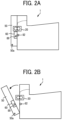
FIGS. 2A and 2B are diagrams illustrating an operation of opening an opening-and-closing cover of the image forming apparatus ofFIG. 1 ; -
FIG. 3 is a schematic view of a secondary transfer unit and a vicinity of the secondary transfer unit; and -
FIG. 4 is a schematic view of a secondary transfer unit and a vicinity of the secondary transfer unit, according to a modification. - The accompanying drawings are intended to depict embodiments of the present disclosure and should not be interpreted to limit the scope thereof. The accompanying drawings are not to be considered as drawn to scale unless explicitly noted. Also, identical or similar reference numerals designate identical or similar components throughout the several views.
- In describing embodiments illustrated in the drawings, specific terminology is employed for the sake of clarity. However, the disclosure of this specification is not intended to be limited to the specific terminology so selected and it is to be understood that each specific element includes all technical equivalents that have a similar function, operate in a similar manner, and achieve a similar result.
- Referring now to the drawings, embodiments of the present disclosure are described below. Like reference signs are assigned to like elements or components and descriptions of those elements or components may be simplified or omitted. As used herein, the singular forms "a," "an," and "the" are intended to include the plural forms as well, unless the context clearly indicates otherwise.
- First, with reference to
FIG. 1 , a description is given of an overall configuration and operation of animage forming apparatus 1 according to an embodiment of the present disclosure. As illustrated inFIG. 1 , theimage forming apparatus 1 according to the present embodiment is a tandem-type color printer. Fourtoner bottles bottle housing 101 located above a body of theimage forming apparatus 1. Anintermediate transfer unit 85 is disposed below thebottle housing 101.Image forming devices intermediate transfer unit 85. Theimage forming apparatus 1 includes a sheet feeder 12 (a sheet tray) in a lower portion of the body of theimage forming apparatus 1. Thesheet feeder 12 stores a stack of multiple sheets P such as sheets of paper stacked on one on another. On the left of theimage forming apparatus 1, an opening-and-closing cover 50 for exposing the inside of the image forming apparatus 1 (for example, conveyance paths K0 andK 1 of the sheet P, and a fixing device 20) is disposed to be openable and closable. - The
image forming devices photoconductor drums photoconductor drums charger 75, a developingdevice 76, acleaner 77, and a charge eliminating device. Image forming processes including a charging process, an exposure process, a developing process, a primary transfer process, and a cleaning process are performed on each of thephotoconductor drums photoconductor drums - A main motor drives to rotate the
photoconductor drums FIG. 1 . Thecharger 75 disposed opposite each of thephotoconductor drums photoconductor drums photoconductor drums photoconductor drums - After the exposure process, the irradiated and scanned outer circumferential surface of each of the
photoconductor drums device 76 is disposed opposite each of thephotoconductor drums device 76 develops the electrostatic latent image formed on therespective photoconductor drums photoconductor drums photoconductor drums photoconductor drums intermediate transfer belt 78 by four primarytransfer bias rollers photoconductor drums intermediate transfer belt 78, respectively, and the yellow, magenta, cyan, and black toner images are primarily transferred onto the intermediate transfer belt 78 (a primary transfer process). After the primary transfer process, residual toner (untransferred toner) onto theintermediate transfer belt 78 slightly remains on thephotoconductor drums - After the primary transfer process, the residual toner (untransferred toner) on each of the
photoconductor drums cleaner 77 is disposed opposite each of thephotoconductor drums cleaner 77 mechanically collects the residual toner from each of thephotoconductor drums photoconductor drums photoconductor drums photoconductor drums photoconductor drums - The yellow, magenta, cyan, and black toner images formed on the
photoconductor drums intermediate transfer belt 78. Thus, a color toner image is formed on the surface of theintermediate transfer belt 78. Theintermediate transfer unit 85 includes theintermediate transfer belt 78 as an intermediate transferor, the four primarytransfer bias rollers transfer backup roller 82, acleaning backup roller 83, atension roller 84, and anintermediate transfer cleaner 80. Theintermediate transfer belt 78 is extended and supported by the three rollers, that is, the secondary-transfer backup roller 82, thecleaning backup roller 83, and atension roller 84. One of the three rollers, that is, the secondary-transfer backup roller 82 is coupled to the main motor to drive and rotate theintermediate transfer belt 78 in a rotation direction indicated by an arrow inFIG. 1 . - The four primary
transfer bias rollers corresponding photoconductor drums intermediate transfer belt 78 to form primary transfer nips. Each of the primarytransfer bias rollers intermediate transfer belt 78 moves in the direction indicated by the arrow inFIG. 1 and sequentially passes through the primary transfer nips of the primarytransfer bias rollers respective photoconductor drums intermediate transfer belt 78 while being superimposed one atop another to form a composite color toner image on the intermediate transfer belt 78 (a primary transfer process). - Subsequently, the
intermediate transfer belt 78 to which the superimposed toner images of yellow, magenta, cyan, and black have been transferred reaches a position opposite (facing) asecondary transfer roller 89 as a transferor. At this position, the secondary-transfer backup roller 82 and the secondary transfer roller 89 (transferor) nip theintermediate transfer belt 78 therebetween to form a secondary transfer nip. The toner images of four colors formed on theintermediate transfer belt 78 are transferred (secondarily transferred) onto the sheet P conveyed to the position of the secondary transfer nip (a secondary transfer process). At this time, untransferred toner that is not transferred onto the sheet P remains on the surface of theintermediate transfer belt 78. The surface of theintermediate transfer belt 78 then reaches a position opposite theintermediate transfer cleaner 80. At this position, theintermediate transfer cleaner 80 collects the untransferred toner from theintermediate transfer belt 78. Thus, a series of transfer processes performed on theintermediate transfer belt 78 is completed. - The sheet P is conveyed from the
sheet feeder 12 disposed in the lower portion of the body of theimage forming apparatus 1 to the secondary transfer nip via the conveyance path K0. Specifically, thesheet feeder 12 contains a stack of multiple sheets P (transfer media) such as sheets of paper stacked on one on another. As asheet feed roller 31 is rotated counterclockwise inFIG. 1 , the uppermost sheet P nipped between thesheet feed roller 31 and afriction pad 32 is fed toward between the rollers of a registration roller pair 33 (timing roller pair) while the sheet P is guided by guide plates forming the conveyance path K0. - The sheet P conveyed to the
registration roller pair 33 serving as a timing roller pair temporarily stops at a position of a roller nip (nip portion) of theregistration roller pair 33 that stops rotating. Rotation of theregistration roller pair 33 is timed to convey the sheet P toward the secondary transfer nip such that the sheet P as a transfer medium meets the color toner image on theintermediate transfer belt 78 at the secondary transfer nip. Thus, the desired color toner image is transferred onto the sheet P. - Subsequently, the sheet P, onto which the color toner image is transferred at the secondary transfer nip, is conveyed to a position of a fixing
device 20 via a conveyance path. At this point, that is, at a fixing nip formed by a fixingbelt 21 and apressure roller 22 pressing each other, the toner image transferred onto the surface of the sheet P is fixed onto the sheet P by heat and pressure from a fixing belt (a fixing process). - After the fixing process, the sheet P bearing the fixed toner image is conveyed through the conveyance path K1 and ejected by a sheet
ejection roller pair 40 to the outside of theimage forming apparatus 1. The sheets P ejected one by one by the sheetejection roller pair 40 to the outside of theimage forming apparatus 1 are sequentially stacked as output images on astacker 100. Thus, a series of image forming processes performed by theimage forming apparatus 1 is completed. - With reference to
FIGS. 2A, 2B , and3 , a description is given of a configuration and operation of theimage forming apparatus 1 according to the present embodiment in detail below. As described above with reference toFIG. 1 , the opening-and-closing cover 50 for opening and closing the inside of theimage forming apparatus 1 is disposed on the left of theimage forming apparatus 1 according to the present embodiment. With reference toFIGS. 2A and 2B , the opening-and-closing cover 50 is rotatable around asupport shaft 50a in order to open and close the inside of theimage forming apparatus 1. The opening-and-closing cover 50 holds a secondary transfer unit 60 (which holds a secondary transfer roller 89) to be described later. Accordingly, thesecondary transfer unit 60 is rotated around thesupport shaft 50a together with the opening-and-closing cover 50 in conjunction with the opening and closing operation of the opening-and-closing cover 50. - Specifically, when the opening-and-
closing cover 50 in a closed state as illustrated inFIG. 2A (andFIG. 1 ) is rotated clockwise (in the direction indicated by the arrow inFIG. 2B ) around thesupport shaft 50a together with thesecondary transfer unit 60 as illustrated inFIG. 2B , a part of the inside of the image forming apparatus 1 (for example, the first conveyance path K0, the second conveyance path K1, thesecondary transfer unit 60, and the fixing device 20) is opened (exposed), so that the sheet P jammed in the first conveyance path K0, the second conveyance path K1, and the fixingdevice 20 can be removed, and attachment and detachment of thesecondary transfer unit 60 and the fixingdevice 20 for maintenance can be performed. When the opening-and-closing cover 50 in an open state as illustrated inFIG. 2B is rotated clockwise inFIG. 2B around thesupport shaft 50a together with thesecondary transfer unit 60, the opening-and-closing cover 50 turns to a closed state as illustratedFIGS. 2A and3 , and then thesecondary transfer roller 89 contacts theintermediate transfer belt 78 to form the secondary transfer nip. - As described above with reference to
FIG. 1 , theimage forming apparatus 1 according to the present embodiment includes thesecondary transfer roller 89 as a transfer member for transferring an image onto the sheet P as a transfer medium. Thesecondary transfer roller 89 as a transfer member is a roller that contacts theintermediate transfer belt 78 as an intermediate transferor to form a secondary transfer nip, and secondarily transfers an image primarily transferred onto theintermediate transfer belt 78 onto the sheet P as a transfer medium conveyed to the secondary transfer nip. Thesecondary transfer roller 89 includes ashaft 89a (seeFIG. 3 ) made of a conductive material such as stainless steel. An elastic layer is formed (coated) on theshaft 89a. The elastic layer of thesecondary transfer roller 89 is a solid rubber or a foam-sponge rubber made of, e.g., polyurethane, ethylene-propylene-diene monomer (EPDM), or silicone having a conductive filler such as carbon dispersed or containing an ionic conductive material. - With reference to
FIG. 3 , theimage forming apparatus 1 according to the present embodiment includes apower supply 110 for outputting a transfer bias (a secondary transfer bias) to be applied to the secondary transfer roller 89 (transfer member). Thepower supply 110 applies the secondary transfer bias having a polarity different from the polarity of the toner to thesecondary transfer roller 89 to form a secondary-transfer electric field at the position of the secondary transfer nip, the toner borne on the outer circumferential surface (toner bearing surface) of theintermediate transfer belt 78 is electrostatically moved toward thesecondary transfer roller 89. The secondary transfer bias may be a direct-current voltage, or a direct-current voltage on which an alternating-current voltage is superimposed. - With reference to
FIG. 3 (andFIGS. 2A and 2B ), theimage forming apparatus 1 according to the present embodiment includes thesecondary transfer unit 60 as a transfer unit that holds the secondary transfer roller 89 (transfer member). The secondary transfer unit 60 (transfer unit) is supported to be rotatable around thesupport shaft 50a with respect to the body of theimage forming apparatus 1. Specifically, as described above with reference toFIGS. 2A and 2B , thesecondary transfer unit 60 is held by the opening-and-closing cover 50 that is rotatable (openable and closable) around thesupport shaft 50a. Thesecondary transfer unit 60 includes aconveyance guide 62 that guides the sheet P sent out from the secondary transfer nip, in addition to a holdingportion 61 that rotatably holds thesecondary transfer roller 89. - The
conveyance guide 62 of thesecondary transfer unit 60 is a member that is disposed downstream from the secondary transfer nip in a sheet conveyance direction and upstream from a fixingentrance guide 23 of the fixingdevice 20 in the sheet conveyance direction, and guides the sheet P sent out from the secondary transfer nip toward the fixing device 20 (fixing entrance guide 23) after the secondary transfer process. - The holding
portion 61 of thesecondary transfer unit 60 holds a bearing that rotatably holds theshaft 89a of thesecondary transfer roller 89 such that a part of thesecondary transfer roller 89 fits into a concave portion (a portion recessed in a direction away from the secondary transfer nip). The secondary transfer unit 60 (holding portion 61) includes afitting member 90 that fits to theshaft 89a of thesecondary transfer roller 89 and asecond compression spring 91 as a second urging member that urges thefitting member 90 such that thesecondary transfer roller 89 contacts the intermediate transfer belt 78 (intermediate transferor). Thefitting member 90 fits into a groove (in which thesecond compression spring 91 is disposed) formed in the holdingportion 61 and is slidable in the left- and-right direction (a direction in which the groove extends, and a direction in which thefitting member 90 contacts and separates from the intermediate transfer belt 78) inFIG. 3 . - With reference to
FIG. 3 , theimage forming apparatus 1 according to the present embodiment includes afirst compression spring 93 serving as an urging member that urges the secondary transfer unit 60 (transfer unit) such that thesecondary transfer unit 60 contacts apositioning portion 23a of the body of theimage forming apparatus 1. Specifically, thepositioning portion 23a is a portion that protrudes downward at an end of the fixingentrance guide 23 of the fixingdevice 20 in the width direction (the direction perpendicular to the plane on whichFIG. 3 is illustrated). On the other hand, theconveyance guide 62 of thesecondary transfer unit 60 has acontact portion 62a (the portion protruding in a boss shape in the width direction) that contacts thepositioning portion 23a at an end of theconveyance guide 62 in the width direction. Thesecondary transfer unit 60 is urged obliquely to the upper right inFIG. 3 by the first compression springs 93 disposed at the end of theconveyance guide 62 in the width direction, such that thecontact portion 62a of thesecondary transfer unit 60 contacts thepositioning portion 23a, and thus the position of thesecondary transfer unit 60 in theimage forming apparatus 1 is accurately determined. Accordingly, the position of the secondary transfer nip is accurately determined, so that the secondary transfer process is preferably performed. The position of theconveyance guide 62 in theimage forming apparatus 1 is also accurately determined, so that the performance of conveying the sheet P from the secondary transfer nip to the fixing nip is also enhanced. The components (for example, thefirst compression spring 93, thecontact portion 62a, and thepositioning portion 23a) related to the positioning of thesecondary transfer unit 60 are disposed at both ends of thesecondary transfer unit 60 in the width direction. In order to efficiently perform the positioning as described above, it is preferable that the urging direction of thefirst compression spring 93 and the direction in which thecontact portion 62a contacts thepositioning portion 23a coincide with each other. - In the present embodiment, the
secondary transfer unit 60 is held to be movable in a direction in which thesecondary transfer unit 60 contacts theintermediate transfer belt 78 in the opening-and-closing cover 50 and a direction in which thesecondary transfer unit 60 separates from theintermediate transfer belt 78 in the opening-and-closing cover 50. Thefirst compression spring 93 is disposed on a body of the opening-and-closing cover 50 (indirectly disposed on the body of the image forming apparatus 1) and is disposed to urge thesecondary transfer unit 60 in the above-described direction in the opening-and-closing cover 50. On the other hand, thesecondary transfer unit 60 may be fixed to the opening-and-closing cover 50, and thefirst compression spring 93 may be directly disposed in the body of theimage forming apparatus 1 without using the opening-and-closing cover 50. In this case, the entire positioning of the opening-and-closing cover 50 is determined by the contact between the positioningportion 23a and thecontact portion 62a of thesecondary transfer unit 60. In the present embodiment, thepositioning portion 23a with which thecontact portion 62a of thesecondary transfer unit 60 contacts is disposed in the fixingentrance guide 23 of the fixingdevice 20. However, the position (member) where the positioning portion is disposed is not limited thereto. - The
first compression spring 93 serving as an urging member in the present embodiment functions as a part of a power supply path of the secondary transfer bias from thepower supply 110 to the secondary transfer roller 89 (transfer member). Specifically, thefirst compression spring 93 is made of a conductive material such as metal, and one end of thefirst compression spring 93 is connected to thepower supply 110 via a first power supply path 94 (for example, formed of a harness). Thesecond compression spring 91 and thefitting member 90 of the secondary transfer unit 60 (holding portion 61) described above are made of a conductive material such as metal or conductive resin. The secondary transfer unit 60 (holding portion 61) includes aconductive plate 92. One end of theconductive plate 92 is connected to the second compression spring 91 (second urging member), and the other end of theconductive plate 92 is connected to acontact portion 93a, which is conductive and has a certain degree of rigidity, formed on the other end of thefirst compression spring 93. With such a configuration, the secondary transfer bias (transfer bias) output from the power supply 110 (first power supply path 94) is applied to theshaft 89a of thesecondary transfer roller 89 via thefirst compression spring 93, theconductive plate 92, the second compression spring 91 (second urging member), and thefitting member 90. Components that function only as power supply paths (mainly theconductive plate 92 or the first power supply path 94) without being related to the positioning of thesecondary transfer unit 60 are not disposed at both ends in the width direction, but are disposed only at one end in the width direction. - As described above, in the present embodiment, the first compression spring 93 (urging member) having a function of positioning the
secondary transfer unit 60 with respect to the body of theimage forming apparatus 1 also functions as a power supply path for applying the secondary transfer bias from thepower supply 110 to thesecondary transfer roller 89. Such a configuration allows the simplified structure and cost reduction of theimage forming apparatus 1 compared to a case where a member having a positioning function and a member having a power supply function are separately disposed. In the present embodiment, the first compression spring 93 (urging member) functions as a part of the power supply path of the secondary transfer bias from thepower supply 110 to thesecondary transfer roller 89. However, thefirst compression spring 93 may be directly connected to thesecondary transfer roller 89 to function as the entire power supply path. - As illustrated in
FIG. 4 , the secondary transfer unit 60 (transfer unit) according to the modification includes acharge eliminating member 70 that eliminates charge of the sheet P sent out from the secondary transfer nip between theconveyance guide 62 and the holdingportion 61 that rotatably holds thesecondary transfer roller 89. Thecharge eliminating member 70 includes a needle-shapedcharge eliminating plate 70a at the tip thereof, and eliminates the charge accumulated on the sheet P after the secondary transfer process to reduce the inconvenience of the sheet P being electrostatically attracted to theconveyance guide 62. In the modification, thefirst compression spring 93 having the function of positioning thesecondary transfer unit 60 also has a function of determining the position of thecharge eliminating member 70 in theimage forming apparatus 1. Accordingly, the above-described charge eliminating function of thecharge eliminating member 70 is preferably exhibited. - As described above, the
image forming apparatus 1 according to the present embodiment includes the secondary transfer roller 89 (transfer member) for transferring an image onto the sheet P (transfer medium), and the secondary transfer unit 60 (transfer unit) that is supported to be rotatable around thesupport shaft 50a with respect to the body of theimage forming apparatus 1 and holds thesecondary transfer roller 89. Theimage forming apparatus 1 further includes thepower supply 110 that outputs the secondary transfer bias (transfer bias) to be applied to thesecondary transfer roller 89, and the first compression spring 93 (urging member) that urges thesecondary transfer unit 60 such that thesecondary transfer unit 60 contacts thepositioning portion 23a of the body of theimage forming apparatus 1. Thefirst compression spring 93 functions as a part or all of a power supply path of the secondary transfer bias from thepower supply 110 to thesecondary transfer roller 89. Such a configuration easily performs the positioning of thesecondary transfer unit 60 in which the secondary transfer roller 89 (transfer member) is held with respect to the body of theimage forming apparatus 1, and the supply of power to thesecondary transfer roller 89. - In the present embodiment, the present disclosure is applied to the color
image forming apparatus 1. However, the present disclosure is applied to a monochrome image forming apparatus as well. In this case, the transfer member to which the present disclosure is applied is, for example, a transfer roller that contacts a photoconductor such as a photoconductor drum to form a transfer nip through which a sheet P as a transfer medium is conveyed. In the present embodiment, thesecondary transfer roller 89 is used as a transfer member to which the present disclosure is applied. However, each of the primarytransfer bias rollers intermediate transfer belt 78. In the present embodiment, thesecondary transfer roller 89 that contacts theintermediate transfer belt 78 to form a transfer nip is used as a transfer member to which the present disclosure is applied. However, a secondary transfer charger that faces theintermediate transfer belt 78 without contact may be used as the transfer member to which the present disclosure is applied. In the present embodiment, thefirst compression spring 93 is used as an urging member having the positioning function and the power supplying function. However, the urging member is not limited thereto, and for example, a plate spring may be used. Even in such a case, advantageous effects equivalent to the effects of the above-described embodiments can be obtained. - The above-described embodiments and modifications are illustrative and do not limit this disclosure. Thus, numerous additional modifications and variations are possible in light of the above teachings. For example, elements and/or features of different illustrative and exemplary embodiments herein may be combined with each other and/or substituted for each other within the scope of this disclosure and appended claims. Further, features of components of the embodiments, such as the number, the position, and the shape are not limited the embodiments and thus may be preferably set.
- Aspects of the present disclosure may be, for example, combinations of first to fifth aspects as follows.
- An image forming apparatus (e.g., the image forming apparatus 1) includes a transfer member (e.g., the secondary transfer roller 89) to transfer an image onto a transfer medium, a transfer unit (e.g., the secondary transfer unit 60) that is supported to be rotatable around a support shaft (e.g., the
support shaft 50a) with respect to a body of the image forming apparatus and holds the transfer member, a power supply (e.g., the power supply 110) to output a transfer bias to be applied to the transfer member, and an urging member (e.g., the first compression spring 93) to urge the transfer unit such that the transfer unit contacts a positioning portion (e.g., thepositioning portion 23a) of the body of the image forming apparatus. The urging member functions as a part or all of a power supply path (e.g., theconductive plate 92, the first power supply path 94) of the transfer bias from the power supply to the transfer member. - In the image forming apparatus (e.g., the image forming apparatus 1) according to the first aspect, the transfer member (e.g., the secondary transfer roller 89) is a secondary transfer roller that contacts an intermediate transfer member (e.g., the intermediate transfer belt 78) to form a secondary transfer nip and secondarily transfers the image, which has been primarily transferred onto the intermediate transfer member, to a sheet (e.g., the sheet P) as the transfer medium conveyed to the secondary transfer nip. The urging member (e.g., the first compression spring 93) is a compression spring made of a conductive material.
- In the image forming apparatus (e.g., the image forming apparatus 1) according to the second aspect, the transfer unit (e.g., the secondary transfer unit 60) includes a fitting member (e.g., the fitting member 90) that fits to a shaft (e.g., the
shaft 89a) of the secondary transfer roller, a second urging member (e.g., the second compression spring 91) that urges the fitting member such that the secondary transfer roller contacts the intermediate transfer member (e.g., the intermediate transfer belt 78), and a conductive plate (e.g., the conductive plate 92) having one end connected to the second urging member and the other end connected to the compression spring. The transfer bias output from the power supply (e.g., the power supply 110) is applied to the secondary transfer roller via the compression spring, the conductive plate, the second urging member, and the fitting member. - In the image forming apparatus (e.g., the image forming apparatus 1) according to the second or third aspect, the transfer unit (e.g., the secondary transfer unit 60) includes a conveyance guide (e.g., the conveyance guide 62) to guide the sheet (e.g., the sheet P) sent out from the secondary transfer nip. The conveyance guide includes a contact portion (e.g., the
contact portion 62a) that contacts the positioning portion (e.g., the positioningportion 23 a). - In the image forming apparatus (e.g., the image forming apparatus 1) according to the fourth aspect, the transfer unit (e.g., the secondary transfer unit 60) includes a charge eliminating member (e.g., the charge eliminating member 70) to eliminate charge of the sheet (e.g., the sheet P) sent out from the secondary transfer nip. The charge eliminating member is disposed between the conveyance guide (e.g., the conveyance guide 62) and a holding portion (e.g., the holding portion 61) that rotatably holds the secondary transfer roller.
- The above-described embodiments are illustrative and do not limit the present invention. Thus, numerous additional modifications and variations are possible in light of the above teachings. For example, elements and/or features of different illustrative embodiments may be combined with each other and/or substituted for each other within the scope of the present invention.
Claims (5)
- An image forming apparatus (1) comprising:a body;a transfer member (89) to transfer an image onto a transfer medium (P);a transfer unit (60) supported to rotate around a support shaft (50a) with respect to the body, the transfer unit (60) holding the transfer member (89);a power supply (110) to output a transfer bias to be applied to the transfer member (89); andan urging member (93) urging the transfer unit (60) in a direction in which the transfer unit (60) contacts a positioning portion (23a) of the body, the urging member (93) being a part or all of a power supply path (92, 94) of the transfer bias from the power supply (110) to the transfer member (89).
- The image forming apparatus (1) according to claim 1,wherein the transfer member (89) is a secondary transfer roller that contacts an intermediate transfer member (78) to form a secondary transfer nip and secondarily transfer the image, which has been primarily transferred onto the intermediate transfer member (78), to a sheet (P) as the transfer medium (P) conveyed to the secondary transfer nip, andwherein the urging member (93) is a compression spring made of a conductive material.
- The image forming apparatus (1) according to claim 2,wherein the transfer unit (60) includes:a fitting member (90) to fit to a shaft (89a) of the secondary transfer roller;another urging member (91) urging the fitting member (90) in a direction in which the secondary transfer roller contacts the intermediate transfer member (78); anda conductive plate (92) having one end connected to said another urging member (91) and another end connected to the compression spring, andwherein the transfer bias output from the power supply (110) is applied to the secondary transfer roller via the compression spring, the conductive plate (92), said another urging member (91), and the fitting member (90).
- The image forming apparatus (1) according to claim 2 or 3,wherein the transfer unit (60) includes a conveyance guide (62) to guide the sheet (P) sent out from the secondary transfer nip, andwherein the conveyance guide (62) includes a contact portion (62a) that contacts the positioning portion (23a).
- The image forming apparatus (1) according to claim 4,wherein the transfer unit (60) includes:a holding portion (61) rotatably holding the secondary transfer roller; anda charge eliminating member (70) to eliminate charge of the sheet (P) sent from the secondary transfer nip, andwherein the charge eliminating member (70) is disposed between the conveyance guide (62) and the holding portion (61).
Applications Claiming Priority (1)
| Application Number | Priority Date | Filing Date | Title |
|---|---|---|---|
| JP2023138709A JP2025033172A (en) | 2023-08-29 | 2023-08-29 | Image forming device |
Publications (1)
| Publication Number | Publication Date |
|---|---|
| EP4517434A1 true EP4517434A1 (en) | 2025-03-05 |
Family
ID=92106754
Family Applications (1)
| Application Number | Title | Priority Date | Filing Date |
|---|---|---|---|
| EP24191162.7A Pending EP4517434A1 (en) | 2023-08-29 | 2024-07-26 | Image forming apparatus |
Country Status (4)
| Country | Link |
|---|---|
| US (1) | US20250076789A1 (en) |
| EP (1) | EP4517434A1 (en) |
| JP (1) | JP2025033172A (en) |
| CN (1) | CN119535930A (en) |
Citations (6)
| Publication number | Priority date | Publication date | Assignee | Title |
|---|---|---|---|---|
| JP2001100550A (en) * | 1999-09-30 | 2001-04-13 | Fuji Xerox Co Ltd | Image forming device |
| JP4368663B2 (en) | 2003-01-15 | 2009-11-18 | 株式会社リコー | Image forming apparatus and power supply face plate |
| US20100003051A1 (en) * | 2008-07-04 | 2010-01-07 | Sekine Takuya | Transfer unit and image forming apparatus |
| US8478165B2 (en) * | 2009-05-01 | 2013-07-02 | Fuji Xerox Co., Ltd. | Image forming apparatus having an openable member |
| EP3059638A1 (en) * | 2015-02-17 | 2016-08-24 | Kabushiki Kaisha Toshiba | Image forming apparatus |
| JP2019133008A (en) | 2018-01-31 | 2019-08-08 | シャープ株式会社 | Image forming apparatus |
Family Cites Families (5)
| Publication number | Priority date | Publication date | Assignee | Title |
|---|---|---|---|---|
| EP0515164A3 (en) * | 1991-05-20 | 1993-11-03 | Canon Kk | Charger having charging blade, image forming apparatus having same and process cartridge having same |
| JP4270107B2 (en) * | 2004-11-04 | 2009-05-27 | 船井電機株式会社 | Image forming apparatus |
| JP5822124B2 (en) * | 2011-02-10 | 2015-11-24 | 株式会社リコー | CONNECTION DEVICE, AND CHARGING DEVICE, IMAGE FORMING DEVICE, AND PROCESS CARTRIDGE HAVING THE CONNECTION DEVICE |
| JP2021018395A (en) * | 2019-07-24 | 2021-02-15 | ヒューレット−パッカード デベロップメント カンパニー エル.ピー.Hewlett‐Packard Development Company, L.P. | Prevention of polarization of transfer roller using ion conductive material |
| JP2022075315A (en) * | 2020-11-06 | 2022-05-18 | 富士フイルムビジネスイノベーション株式会社 | Transfer device, image forming device, and endless belt |
-
2023
- 2023-08-29 JP JP2023138709A patent/JP2025033172A/en active Pending
-
2024
- 2024-07-26 EP EP24191162.7A patent/EP4517434A1/en active Pending
- 2024-07-26 US US18/785,707 patent/US20250076789A1/en active Pending
- 2024-07-30 CN CN202411027323.XA patent/CN119535930A/en active Pending
Patent Citations (6)
| Publication number | Priority date | Publication date | Assignee | Title |
|---|---|---|---|---|
| JP2001100550A (en) * | 1999-09-30 | 2001-04-13 | Fuji Xerox Co Ltd | Image forming device |
| JP4368663B2 (en) | 2003-01-15 | 2009-11-18 | 株式会社リコー | Image forming apparatus and power supply face plate |
| US20100003051A1 (en) * | 2008-07-04 | 2010-01-07 | Sekine Takuya | Transfer unit and image forming apparatus |
| US8478165B2 (en) * | 2009-05-01 | 2013-07-02 | Fuji Xerox Co., Ltd. | Image forming apparatus having an openable member |
| EP3059638A1 (en) * | 2015-02-17 | 2016-08-24 | Kabushiki Kaisha Toshiba | Image forming apparatus |
| JP2019133008A (en) | 2018-01-31 | 2019-08-08 | シャープ株式会社 | Image forming apparatus |
Also Published As
| Publication number | Publication date |
|---|---|
| US20250076789A1 (en) | 2025-03-06 |
| CN119535930A (en) | 2025-02-28 |
| JP2025033172A (en) | 2025-03-13 |
Similar Documents
| Publication | Publication Date | Title |
|---|---|---|
| US8737865B2 (en) | Image forming apparatus | |
| EP2078990B1 (en) | Image forming apparatus and image forming method capable of effectively transferring toner images | |
| US9046843B2 (en) | Fixing device and image forming apparatus | |
| CN104049501B (en) | Fixing device and image forming apparatus | |
| JP5945931B2 (en) | Image forming apparatus | |
| EP2735912B1 (en) | Transfer device and image forming apparatus including the same | |
| US20200379395A1 (en) | Sheet conveyance device and image forming apparatus incorporating same | |
| US11269271B2 (en) | Roller unit, belt device and image forming apparatus | |
| US9164470B2 (en) | Transfer device and attachment of the transfer device to a cover of an image forming apparatus | |
| US8862018B2 (en) | Cleaning unit and image forming apparatus using the same | |
| US8750734B2 (en) | Transfer device and image forming apparatus including same | |
| US8867971B2 (en) | Developer regulator, development device, and image forming apparatus incorporating same | |
| US20250076789A1 (en) | Image forming apparatus | |
| JP5282464B2 (en) | Transfer unit and image forming apparatus | |
| CN114594666A (en) | Processing unit and image forming apparatus | |
| JP5800220B2 (en) | Image forming apparatus | |
| JP4445347B2 (en) | Image forming apparatus | |
| JP5849533B2 (en) | Image forming apparatus | |
| JP7389951B2 (en) | Conveyance device and image forming device | |
| US20230367257A1 (en) | Image forming apparatus | |
| JP2009063732A (en) | Image forming apparatus | |
| JP2005242169A (en) | Image forming apparatus | |
| JP2007219402A (en) | Image forming apparatus | |
| JP2017181618A (en) | Electrifying device and image forming apparatus | |
| JP2012137787A (en) | Image forming device |
Legal Events
| Date | Code | Title | Description |
|---|---|---|---|
| PUAI | Public reference made under article 153(3) epc to a published international application that has entered the european phase |
Free format text: ORIGINAL CODE: 0009012 |
|
| STAA | Information on the status of an ep patent application or granted ep patent |
Free format text: STATUS: REQUEST FOR EXAMINATION WAS MADE |
|
| 17P | Request for examination filed |
Effective date: 20240726 |
|
| AK | Designated contracting states |
Kind code of ref document: A1 Designated state(s): AL AT BE BG CH CY CZ DE DK EE ES FI FR GB GR HR HU IE IS IT LI LT LU LV MC ME MK MT NL NO PL PT RO RS SE SI SK SM TR |