EP4517375A1 - Ultrasound diagnosis apparatus and ultrasound diagnosis method - Google Patents
Ultrasound diagnosis apparatus and ultrasound diagnosis method Download PDFInfo
- Publication number
- EP4517375A1 EP4517375A1 EP24196682.9A EP24196682A EP4517375A1 EP 4517375 A1 EP4517375 A1 EP 4517375A1 EP 24196682 A EP24196682 A EP 24196682A EP 4517375 A1 EP4517375 A1 EP 4517375A1
- Authority
- EP
- European Patent Office
- Prior art keywords
- transmission
- ultrasound
- processing circuitry
- transmission condition
- wave
- Prior art date
- Legal status (The legal status is an assumption and is not a legal conclusion. Google has not performed a legal analysis and makes no representation as to the accuracy of the status listed.)
- Granted
Links
Images


Classifications
-
- G—PHYSICS
- G01—MEASURING; TESTING
- G01S—RADIO DIRECTION-FINDING; RADIO NAVIGATION; DETERMINING DISTANCE OR VELOCITY BY USE OF RADIO WAVES; LOCATING OR PRESENCE-DETECTING BY USE OF THE REFLECTION OR RERADIATION OF RADIO WAVES; ANALOGOUS ARRANGEMENTS USING OTHER WAVES
- G01S7/00—Details of systems according to groups G01S13/00, G01S15/00, G01S17/00
- G01S7/52—Details of systems according to groups G01S13/00, G01S15/00, G01S17/00 of systems according to group G01S15/00
- G01S7/52017—Details of systems according to groups G01S13/00, G01S15/00, G01S17/00 of systems according to group G01S15/00 particularly adapted to short-range imaging
- G01S7/52023—Details of receivers
- G01S7/52036—Details of receivers using analysis of echo signal for target characterisation
- G01S7/52038—Details of receivers using analysis of echo signal for target characterisation involving non-linear properties of the propagation medium or of the reflective target
-
- A—HUMAN NECESSITIES
- A61—MEDICAL OR VETERINARY SCIENCE; HYGIENE
- A61B—DIAGNOSIS; SURGERY; IDENTIFICATION
- A61B8/00—Diagnosis using ultrasonic, sonic or infrasonic waves
- A61B8/13—Tomography
- A61B8/14—Echo-tomography
-
- A—HUMAN NECESSITIES
- A61—MEDICAL OR VETERINARY SCIENCE; HYGIENE
- A61B—DIAGNOSIS; SURGERY; IDENTIFICATION
- A61B8/00—Diagnosis using ultrasonic, sonic or infrasonic waves
- A61B8/13—Tomography
- A61B8/15—Transmission-tomography
-
- A—HUMAN NECESSITIES
- A61—MEDICAL OR VETERINARY SCIENCE; HYGIENE
- A61B—DIAGNOSIS; SURGERY; IDENTIFICATION
- A61B8/00—Diagnosis using ultrasonic, sonic or infrasonic waves
- A61B8/44—Constructional features of the ultrasonic, sonic or infrasonic diagnostic device
- A61B8/4483—Constructional features of the ultrasonic, sonic or infrasonic diagnostic device characterised by features of the ultrasound transducer
- A61B8/4488—Constructional features of the ultrasonic, sonic or infrasonic diagnostic device characterised by features of the ultrasound transducer the transducer being a phased array
-
- A—HUMAN NECESSITIES
- A61—MEDICAL OR VETERINARY SCIENCE; HYGIENE
- A61B—DIAGNOSIS; SURGERY; IDENTIFICATION
- A61B8/00—Diagnosis using ultrasonic, sonic or infrasonic waves
- A61B8/52—Devices using data or image processing specially adapted for diagnosis using ultrasonic, sonic or infrasonic waves
- A61B8/5207—Devices using data or image processing specially adapted for diagnosis using ultrasonic, sonic or infrasonic waves involving processing of raw data to produce diagnostic data, e.g. for generating an image
-
- A—HUMAN NECESSITIES
- A61—MEDICAL OR VETERINARY SCIENCE; HYGIENE
- A61B—DIAGNOSIS; SURGERY; IDENTIFICATION
- A61B8/00—Diagnosis using ultrasonic, sonic or infrasonic waves
- A61B8/54—Control of the diagnostic device
-
- G—PHYSICS
- G01—MEASURING; TESTING
- G01S—RADIO DIRECTION-FINDING; RADIO NAVIGATION; DETERMINING DISTANCE OR VELOCITY BY USE OF RADIO WAVES; LOCATING OR PRESENCE-DETECTING BY USE OF THE REFLECTION OR RERADIATION OF RADIO WAVES; ANALOGOUS ARRANGEMENTS USING OTHER WAVES
- G01S15/00—Systems using the reflection or reradiation of acoustic waves, e.g. sonar systems
- G01S15/88—Sonar systems specially adapted for specific applications
- G01S15/89—Sonar systems specially adapted for specific applications for mapping or imaging
- G01S15/8906—Short-range imaging systems; Acoustic microscope systems using pulse-echo techniques
- G01S15/8909—Short-range imaging systems; Acoustic microscope systems using pulse-echo techniques using a static transducer configuration
- G01S15/8915—Short-range imaging systems; Acoustic microscope systems using pulse-echo techniques using a static transducer configuration using a transducer array
Definitions
- Embodiments described herein relate generally to an ultrasound diagnosis apparatus and an ultrasound diagnosis method.
- seismic wave interferometry (which may be called a Shot Profile Migration (SPM) or a wave field correlation method) is known.
- the seismic wave interferometry is a method by which an epicenter position or a reflection plane underground is reconstructed and by which the epicenter position or the like is estimated by performing, for example, a correlation process on a transmission wave field obtained through a forward propagation simulation and a reception wave field obtained from a backward propagation simulation.
- Harmonic imaging is important technology as being capable of suppressing echo components from undesired directions. For this reason, when the seismic wave interferometry is applied to an image reconstruction of an ultrasound diagnosis apparatus, it is desirable to be able to carry out harmonic imaging.
- An ultrasound diagnosis apparatus includes transmitter/receiver circuitry and processing circuitry.
- the transmitter/receiver circuitry transmits an ultrasound wave to an examined subject by using a first transmission condition and receives an echo from the examined subject.
- the processing circuitry generates, on a basis of the first transmission condition, a second transmission condition corresponding to transmitting an ultrasound wave obtained by adding a harmonic component to the ultrasound wave, obtains a transmission wave field by forward propagating the ultrasound wave transmitted on a basis of the second transmission condition, obtains a reception wave field by backward propagating a signal based on the echo, and generates a harmonic echo component by performing a correlation analysis between the transmission wave field and the reception wave field.
- the processing circuitry may generate a transmission condition that has a frequency band of a harmonic component in contrast to the first transmission condition and that is same as the first transmission condition except for the frequency band.
- the transmitter/receiver circuitry may transmit ultrasound waves in multiple sessions that are phase-modulated into a mutually same direction and to receive the echo from the examined subject with respect to each of the ultrasound waves transmitted in the multiple sessions.
- the transmiter/receiver circuitry may transmit ultrasound waves in multiple sessions by using a plurality of first transmission conditions including the first transmission condition and receive a plurality of echoes including the echo.
- the processing circuitry may generate a plurality of second transmission conditions including the second transmission condition and respectively corresponding to the plurality of first transmission conditions, obtain the transmission wave field with respect to each of the plurality of second transmission conditions, obtain the reception wave field with respect to each of the echoes respectively corresponding to the plurality of first transmission conditions, perform the correlation analysis between the transmission wave fields and the reception wave fields with respect to the second transmission conditions respectively corresponding to the first transmission conditions and generate the harmonic echo component on a basis of a result of the correlation analysis.
- the transmitter/receiver circuitry may transmit the ultrasound wave by using a first one of the first transmission condition in a first transmission phase to receive a first echo and transmit the ultrasound wave by using a second one of the first transmission condition in a second transmission phase different from the first transmission phase by 180 degrees to receive a second echo.
- the processing circuitry may generate a first one of the second transmission condition on a basis of the first one of the first transmission conditionm, generate a second one of the second transmission condition on a basis of the second one of the first transmission condition, obtain a first transmission wave field on a basis of the first one of the second transmission condition, obtain a second transmission wave field on a basis of the second one of the second transmission condition, obtain a first reception wave field on a basis of the first echo and obtain a second reception wave field on a basis of the second echo.
- the processing circuitry may generate a first signal distribution by performing a correlation analysis between the first transmission wave field and the first reception wave field, generate a second signal distribution by performing a correlation analysis between the second transmission wave field and the second reception wave field, and generate the harmonic echo component on a basis of the first signal distribution and the second signal distribution.
- the processing circuitry may generate the harmonic echo component by performing a subtracting process between the first signal distribution and the second signal distribution.
- the processing circuitry may transmit ultrasound waves in multiple sessions by using a plurality of transmission conditions, receive a plurality of echoes including the echo, handle a process in which the transmitter/receiver circuitry transmits the ultrasound waves in the multiple sessions by using the plurality of transmission conditions and receives the plurality of echoes, as the transmitter/receiver circuitry transmitting a single ultrasound wave by using the first transmission condition being singular.
- the processing circuitry may generate the second transmission condition on a basis of the first transmission condition, obtain the transmission wave field on a basis of the second transmission condition, obtain the reception wave field on a basis of the plurality of echoes,generate the harmonic echo component by performing the correlation analysis between the transmission wave field and the reception wave field.
- the processing circuitry may extract a reception signal containing a harmonic component by combining the plurality of echoes together, and obtain the reception wave field on a basis of the extracted reception signal.
- the processing circuitry may obtain the transmission wave field by forward propagating the ultrasound wave while implementing a simulation method that takes a non-linear component of a medium into consideration.
- the processing circuitry may obtain the reception wave field by backward propagating the signal based on the echo while implementing a simulation method that takes a non-linear component of a medium into consideration.
- the processing circuitry may implement a simulation method that uses an angular spectrum method.
- An ultrasound diagnosis method includes: transmitting an ultrasound wave to an examined subject by using a first transmission condition and receiving an echo from the examined subject; generating, on a basis of the first transmission condition, a second transmission condition corresponding to transmitting an ultrasound wave obtained by adding a harmonic component to the ultrasound wave; obtaining a transmission wave field by forward propagating the ultrasound wave transmitted on a basis of the second transmission condition; obtaining a reception wave field by backward propagating a signal based on the echo; and generating a harmonic echo component by performing a correlation analysis between the transmission wave field and the reception wave field.
- FIG. 1 is a block diagram illustrating an exemplary configuration of the ultrasound diagnosis apparatus according to the first embodiment.
- the ultrasound diagnosis apparatus according to the first embodiment includes an ultrasound probe 5 and an ultrasound diagnosis apparatus 10.
- the ultrasound diagnosis apparatus 10 includes transmitter circuitry 9, receiver circuitry 11, and a medical image processing apparatus 100.
- the ultrasound probe 5 includes a plurality of piezoelectric transducer elements.
- the plurality of piezoelectric transducer elements are configured to generate an ultrasound wave on the basis of a drive signal supplied from the transmitter circuitry 9 (explained later) included in the ultrasound diagnosis apparatus 10.
- the plurality of piezoelectric transducer elements included in the ultrasound probe 5 are configured to receive a reflected wave from an examined subject (hereinafter, "patient") P and convert the received reflected wave into an electrical signal (a reflected-wave signal).
- the ultrasound probe 5 includes a matching layer provided for the piezoelectric transducer elements, a backing member configured to prevent the ultrasound wave from propagating rearward from the piezoelectric transducer elements, and the like. In this situation, the ultrasound probe 5 is detachably connected to the ultrasound diagnosis apparatus 10.
- the transmitted ultrasound wave is repeatedly reflected on a surface of discontinuity of acoustic impedances at a tissue in the body of the patient P, received as the reflected wave by the plurality of piezoelectric transducer elements included in the ultrasound probe 5, and converted into the reflected-wave signal.
- the amplitude of the reflected-wave signal is dependent on the difference between the acoustic impedances on the surface of discontinuity on which the ultrasound wave is reflected.
- the reflected-wave signal is, due to the Doppler effect, subject to a frequency shift, depending on a velocity component of the moving members with respect to the ultrasound wave transmission direction.
- the embodiment is applicable when the ultrasound probe 5 is a one-dimensional (1D) array probe configured to two-dimensionally scan the patient P or is a mechanical four-dimensional (4D) probe or a two-dimensional (2D) array probe configured to three-dimensionally scan the patient P.
- the ultrasound diagnosis apparatus 10 is an apparatus configured to generate ultrasound image data on the basis of the reflected-wave signal received from the ultrasound probe 5.
- the ultrasound diagnosis apparatus 10 illustrated in FIG. 1 is capable of generating two-dimensional ultrasound image data on the basis of a two-dimensional reflected-wave signal and capable of generating three-dimensional ultrasound image data on the basis of a three-dimensional reflected-wave signal.
- the embodiment is also applicable when the ultrasound diagnosis apparatus 10 is an apparatus exclusively for two-dimensional data.
- the ultrasound diagnosis apparatus 10 includes the transmitter circuitry 9, the receiver circuitry 11, and the medical image processing apparatus 100.
- the transmitter circuitry 9 and the receiver circuitry 11 are configured to control the ultrasound wave transmission/reception performed by the ultrasound probe 5 on the basis of an instruction from processing circuitry 150 including a controlling function 150f (explained later).
- the transmitter circuitry 9 includes a pulse generator, a transmission delay unit, a pulser, and the like and is configured to supply the drive signal to the ultrasound probe 5.
- the pulse generator is configured to repeatedly generate a rate pulse used for forming a transmission ultrasound wave at a prescribed Pulse Repetition Frequency (PRF).
- PRF Pulse Repetition Frequency
- the transmission delay unit is configured to apply, to the rate pulses generated by the pulse generator, delay periods that respectively correspond to the piezoelectric transducer elements and are necessary for converging the ultrasound wave generated by the ultrasound probe 5 into the form of a beam and determining transmission directionality.
- the pulser is configured to apply the drive signal (a drive pulse) to the ultrasound probe 5, with timing based on the rate pulses.
- the transmission delay unit is configured to arbitrarily adjust transmission directions of the ultrasound wave transmitted from surfaces of the piezoelectric transducer elements, by varying the delay periods applied to the rate pulses. Also, the transmission delay unit is configured to control the position of a convergence point (a transmission focus) in the depth direction of the ultrasound wave transmission, by varying the delay periods applied to the rate pulses.
- the transmitter circuitry 9 has a function capable of instantaneously changing a transmission frequency, transmission drive voltage, and the like, for executing a predetermined scan sequence on the basis of an instruction from the processing circuitry 150 (explained later).
- the capability to change the transmission drive voltage is realized by transmitter circuitry of a linear amplifier type capable of instantaneously switching the value thereof or a mechanism configured to electrically switch between a plurality of power source units.
- the receiver circuitry 11 includes amplifier circuitry, an Analog/Digital (A/D) converter, reception delay circuitry, an adder, quadrature detection circuitry, and the like and is configured to generate a reception signal (reflected-wave data) by performing various types of processes on the reflected-wave signals received from the ultrasound probe 5.
- the amplifier circuitry is configured to amplify the reflected-wave signal with respect to each channel and to perform a gain correction process.
- the A/D converter is configured to perform an A/D conversion on the gain-corrected reflected-wave signals.
- the reception delay circuitry is configured to apply, to the digital data, a reception delay period necessary for determining reception directionality.
- the adder is configured to perform a process of adding together the reflected-wave signals to which the reception delay period was applied by the reception delay circuitry. As a result of the adding process by the adder, reflected components from a direction corresponding to the reception directionality of the reflected-wave signals are emphasized.
- the quadrature detection circuitry is configured to convert an output signal from the adder into an In-phase signal (an I signal) and a Quadrature-phase signal (a Q signal) in a baseband. After that, the quadrature detection circuitry is configured to transmit the I signal and the Q signal (hereinafter, "IQ signals”) to the processing circuitry 150, as the reception signal (the reflected-wave data). Alternatively, the quadrature detection circuitry may convert the output signal from the adder into a Radio Frequency (RF) signal, which is then transmitted to the processing circuitry 150.
- the IQ signals and the RF signal serve as reception signals including phase information.
- the transmitter circuitry 9 When scanning a two-dimensional region in the patient P, the transmitter circuitry 9 is configured to cause an ultrasound beam for scanning the two-dimensional region to be transmitted from the ultrasound probe 5. Further, the receiver circuitry 11 is configured to generate a two-dimensional reception signal from a two-dimensional reflected-wave signal received from the ultrasound probe 5. In contrast, when scanning a three-dimensional region in the patient P, the transmitter circuitry 9 is configured to cause an ultrasound beam for scanning the three-dimensional region to be transmitted from the ultrasound probe 5. Further, the receiver circuitry 11 is configured to generate a three-dimensional reception signal from a three-dimensional reflected-wave signal received from the ultrasound probe 5. The receiver circuitry 11 is configured to generate a reception signal on the basis of the reflected-wave signal and to transmit the generated reception signal to the processing circuitry 150.
- the transmitter circuitry 9 is configured to cause the ultrasound probe 5 to transmit the ultrasound beam from a predetermined transmission position (a transmission scanning line).
- the receiver circuitry 11 is configured to receive, from the ultrasound probe 5, a signal defined by the reflected wave of the ultrasound beam transmitted by the transmitter circuitry 9, in a predetermined reception position (a reception scanning line). In the situation where a parallel simultaneous reception is not performed, the transmission scanning line and the reception scanning line correspond to the same scanning line.
- the receiver circuitry 11 is configured to simultaneously receive, via the ultrasound probe 5, a signal defined by the reflected wave derived from the ultrasound beam which the transmitter circuitry 9 caused the ultrasound probe 5 to transmit, in a plurality of predetermined reception positions (reception scanning lines) as a plurality of reception beams.
- the medical image processing apparatus 100 is connected to the transmitter circuitry 9 and the receiver circuitry 11 and is configured to process signals received from the receiver circuitry 11 and to exercise control over the transmitter circuitry 9.
- the medical image processing apparatus 100 includes the processing circuitry 150, a memory 132, an input apparatus 134, and a display 135.
- the processing circuitry 150 includes a B-mode processing function 150a, a Doppler processing function 150b, a generating function 150c, a display controlling function 150d, a receiving function 150e, the controlling function 150f, a reconstructing function 150g, a designing function 150h, a first analyzing function 150i, and a second analyzing function 150j.
- processing functions executed by the B-mode processing function 150a, the Doppler processing function 150b, the generating function 150c, the display controlling function 150d, the receiving function 150e, the controlling function 150f, the reconstructing function 150g, the designing function 150h, the first analyzing function 150i, and the second analyzing function 150j are stored in the memory 132 in the form of computer-executable programs.
- the processing circuitry 150 is one or more processors configured to realize the functions corresponding to the programs by reading and executing the programs from the memory 132. In other words, the processing circuitry 150 that has read the programs has the functions illustrated within the processing circuitry 150 in FIG. 1 . Further, although an example will be explained with reference to FIG.
- each of the abovementioned functions may be structured as a program, so that a single piece of processing circuitry executes the program.
- a single piece of processing circuitry may realize two or more of the functions included in the processing circuitry 150.
- one or more specific functions may be installed in dedicated and independent program executing circuitry.
- the processing circuitry 150, the B-mode processing function 150a, the Doppler processing function 150b, the generating function 150c, the display controlling function 150d, the receiving function 150e, the controlling function 150f, the reconstructing function 150g, the designing function 150h, the first analyzing function 150i, and the second analyzing function 150j are examples of a B-mode processing unit, a Doppler processing unit, a generating unit, a display controlling unit, a receiving unit, a controlling unit, a reconstructing unit, a designing unit, a first analyzing unit, and a second analyzing unit, respectively.
- the transmitter circuitry 9 and the receiver circuitry 11 structure an example of a transmission/reception unit.
- processor used in the above explanations denotes, for example, a Central Processing Unit (CPU), a Graphical Processing Unit (GPU), or circuitry such as an Application Specific Integrated Circuit (ASIC) or a programmable logic device (e.g., a Simple Programmable Logic Device (SPLD), a Complex Programmable Logic Device (CPLD), or a Field Programmable Gate Array (FPGA)).
- CPU Central Processing Unit
- GPU Graphical Processing Unit
- ASIC Application Specific Integrated Circuit
- SPLD Simple Programmable Logic Device
- CPLD Complex Programmable Logic Device
- FPGA Field Programmable Gate Array
- the one or more processors are configured to realize the functions by reading and executing the programs incorporated in the circuitry thereof.
- the transmitter circuitry 9, the receiver circuitry 11, and the like built in the ultrasound diagnosis apparatus 10 may be configured by using hardware such as integrated circuitry or may be a program modularized in the form of software.
- the processing circuitry 150 is a processing unit configured to perform various types of signal processing processes on the reception signal received from the receiver circuitry 11.
- the processing circuitry 150 includes the B-mode processing function 150a, the Doppler processing function 150b, the generating function 150c, the display controlling function 150d, the receiving function 150e, the controlling function 150f, the reconstructing function 150g, the designing function 150h, the first analyzing function 150i, and the second analyzing function 150j.
- the processing circuitry 150 is configured to receive data from the receiver circuitry 11 and to generate data (B-mode data) in which signal intensities are expressed as levels of brightness, by performing a logarithmic amplifying process, an envelope detecting process, a logarithmic compressing process, and/or the like.
- the processing circuitry 150 is configured to generate data (Doppler data) obtained by extracting moving member information such as velocity, dispersion, power, and the like caused by the Doppler effect with respect to multiple points, by performing a frequency analysis to obtain velocity information from the reception signal (the reflected-wave data) received from the receiver circuitry 11.
- Doppler data data obtained by extracting moving member information such as velocity, dispersion, power, and the like caused by the Doppler effect with respect to multiple points, by performing a frequency analysis to obtain velocity information from the reception signal (the reflected-wave data) received from the receiver circuitry 11.
- the B-mode processing function 150a and the Doppler processing function 150b illustrated in FIG. 1 are capable of processing both two-dimensional reflected-wave data and three-dimensional reflected-wave data.
- the processing circuitry 150 is configured to exercise control so as to cause the display 135 to display display-purpose ultrasound image data stored in the memory 132.
- the processing circuitry 150 is configured to receive various types of operations from a user, via the input apparatus 134.
- the processing circuitry 150 is configured to control all the processes performed by the ultrasound diagnosis apparatus. More specifically, by employing the controlling function 150f, the processing circuitry 150 is configured to control processes performed by the transmitter circuitry 9, the receiver circuitry 11, and the processing circuitry 150, on the basis of various types of setting requests input by an operator via the input apparatus 134 and various types of control programs and various types of data read from the memory 132.
- the processing circuitry 150 is configured to generate the ultrasound image data from the data generated by the B-mode processing function 150a and the Doppler processing function 150b.
- the processing circuitry 150 is configured to generate two-dimensional B-mode image data in which intensities of the reflected wave are expressed with brightness levels, from two-dimensional B-mode data generated by the B-mode processing function 150a.
- the processing circuitry 150 is configured to generate two-dimensional Doppler image data expressing the moving member information, from two-dimensional Doppler data generated by the Doppler processing function 150b.
- the two-dimensional Doppler image data may be velocity image data, dispersion image data, power image data, or image data combining these types of data.
- the processing circuitry 150 is configured to generate the display-purpose ultrasound image data, by converting (by performing a scan convert process) a scanning line signal sequence from an ultrasound scan into a scanning line signal sequence in a video format used by television, for example. Further, as various types of image processing processes besides the scan convert process, the processing circuitry 150 is configured, by employing the generating function 150c, to perform, for example, an image processing process (a smoothing process) to re-generate an average brightness value image, an image processing process (an edge enhancement process) that uses a differential filter inside an image, or the like, by using a plurality of image frames resulting from the scan convert process. Also, by employing the generating function 150c, the processing circuitry 150 is configured to perform various types of rendering processes on volume data, to generate two-dimensional image data for displaying the volume data on the display 135.
- an image processing process a smoothing process
- an edge enhancement process that uses a differential filter inside an image, or the like
- processing circuitry 150 includes the reconstructing function 150g, the designing function 150h, the first analyzing function 150i, and the second analyzing function 150j. These functions will be explained later.
- the memory 132 is configured by using a semiconductor memory element such as a Random Access Memory (RAM) or a flash memory, or a hard disk, an optical disc, or the like.
- the memory 132 is a memory configured to store therein data such as display-purpose image data generated by the processing circuitry 150. Further, the memory 132 is also capable of storing therein data generated by the B-mode processing function 150a or the Doppler processing function 150b. After a diagnosing process, for example, the operator is able to invoke any of the B-mode data and the Doppler data stored in the memory 132, so that the invoked data serves as the display-purpose ultrasound image data after being routed through the processing circuitry 150. Further, the memory 132 is also capable of storing therein the reception signal (the reflected-wave data) output by the receiver circuitry 11.
- the reception signal the reflected-wave data
- the memory 132 is configured to store therein, as necessary, control programs for performing the ultrasound wave transmission/reception, image processing processes, and display processes, as well as diagnosis information (e.g., a patient ID, a medical doctor's observations, etc.) and various types of data such as diagnosis protocols and various types of body marks.
- diagnosis information e.g., a patient ID, a medical doctor's observations, etc.
- various types of data such as diagnosis protocols and various types of body marks.
- the input apparatus 134 is configured to receive various types of instructions and inputs of information from the operator.
- the input apparatus 134 may be pointing equipment such as a mouse or a trackball, selecting equipment such as a mode changing switch, and/or input equipment such as a keyboard.
- the display 135 is configured to display, among others, a Graphical User Interface (GUI) used for receiving inputs of image taking conditions, images generated by the generating function 150c or the like.
- GUI Graphical User Interface
- the display 135 is display equipment such as a liquid display monitor.
- the display 135 is an example of a display unit.
- the display 135 includes a mouse, a keyboard, a button, a panel switch, a touch command screen, a foot switch, a trackball, a joystick, and/or the like.
- seismic wave interferometry (which may be called a Shot Profile Migration (SPM) or a wave field correlation method) is known.
- the seismic wave interferometry is a method by which an epicenter position or a reflection plane underground is reconstructed and by which the epicenter position or the like is estimated by performing, for example, a correlation process on a transmission wave field obtained through a forward propagation simulation and a reception wave field obtained through a backward propagation simulation.
- Harmonic imaging is important technology as being capable of suppressing echo components from undesired directions. For this reason, when the seismic wave interferometry is applied to an image reconstruction of an ultrasound diagnosis apparatus, it is desirable to be able to carry out harmonic imaging.
- Non-Patent Literature 1 proposes an ultrasound image reconstructing method to which seismic wave interferometry is applied.
- a transmission sound field is obtained through a forward propagation simulation, on the basis of a transmission signal from piezoelectric transducer elements, which means that a harmonic component generated in the process of the transmission signal propagating through a living body is not taken into consideration.
- the ultrasound diagnosis apparatus of the embodiment is based on the background described above.
- the ultrasound diagnosis apparatus according to the embodiment includes the transmission/reception unit and the processing circuitry 150.
- the transmission/reception unit is configured to transmit an ultrasound wave to a patient by using a first transmission condition and to receive an echo from the patient.
- the processing circuitry 150 is configured, on the basis of the first transmission condition, to generate a second transmission condition corresponding to transmitting an ultrasound wave obtained by adding a harmonic component to the ultrasound wave.
- the processing circuitry 150 is configured to obtain a transmission wave field by forward propagating the ultrasound wave transmitted on the basis of the second transmission condition.
- the processing circuitry 150 is configured to obtain a reception wave field by backward propagating a signal based on the echo.
- the processing circuitry 150 is configured to generate a harmonic echo component by performing a correlation analysis between the transmission wave field and the reception wave field.
- an ultrasound diagnosis method includes: transmitting an ultrasound wave to a patient by using a first transmission condition and receiving an echo from the patient; generating, on the basis of the first transmission condition, a second transmission condition corresponding to transmitting an ultrasound wave obtained by adding a harmonic component to the ultrasound wave; obtaining a transmission wave field by forward propagating the ultrasound wave transmitted on the basis of the second transmission condition; obtaining a reception wave field by backward propagating a signal based on the echo; and generating a harmonic echo component by performing a correlation analysis between the transmission wave field and the reception wave field.
- the seismic wave interferometry it is possible to apply the seismic wave interferometry to the harmonic imaging of the ultrasound diagnosis apparatus. For example, it is possible to reconstruct an ultrasound image, while keeping a high capability to suppress echo components from undesired directions, to an extent equal to or higher than capabilities of beam forming technology.
- FIG. 2 is a schematic chart for explaining a process performed when the seismic interferometry is simply applied to an ultrasound diagnosis apparatus.
- FIG. 3 is a flowchart indicating the process performed by the ultrasound diagnosis apparatus 10 when the seismic interferometry is simply applied to the ultrasound diagnosis apparatus.
- the flowchart illustrated in FIG. 2 is different from the flowchart in FIG. 4 illustrating processes for performing harmonic imaging in that the process at step S200 (explained later) is not performed and that step S300X is performed in FIG. 2 in place of step S300 in FIG. 4 .
- the transmitter circuitry 9 and the receiver circuitry 11 serving as the transmission/reception unit transmit an ultrasound wave to a patient by using the first transmission condition and receive an echo from the patient.
- the ultrasound diagnosis apparatus 10 employs the transmitter circuitry 9 to transmit ultrasound waves in multiple sessions into mutually-different directions, so that the receiver circuitry 11 receives an echo from the patient with respect to each of the ultrasound waves transmitted in the multiple sessions.
- the transmitter circuitry 9 transmits ultrasound waves 20a, 20b, and 20c in multiple sessions.
- the receiver circuitry 11 receives echoes 40a, 40b, and 40c from the patient, respectively, and thus acquires, as reception signals 50, reception signals r 1 (x,t), r 2 (x,t), and r 3 (x,t) where x denotes a position coordinate of the ultrasound beam in the advancement direction, whereas t denotes a time.
- the first transmission condition denotes, typically, a transmission condition such as an amplitude, a phase, a frequency, a transmission aperture, or transmission apodization of the ultrasound wave to be transmitted.
- the transmitter circuitry 9 transmits the ultrasound wave 20a by using transmission condition #1, transmits the ultrasound wave 20b by using transmission condition #2, and transmits the ultrasound wave 20c by using transmission condition #3.
- transmission condition #1, transmission condition #2, and transmission condition #3 are collectively regarded as a single transmission condition and will be handled as a first transmission condition 20.
- the processing circuitry 150 calculates transmission wave fields 30, by forward propagating the ultrasound waves transmitted on the basis of the first transmission condition, through a forward propagation simulation.
- the processing circuitry 150 may be configured to calculate transmission wave fields f 1 (x,y,t), f 2 (x,y,t), and f 3 (x,y,t) by forward propagating the ultrasound wave 20a, the ultrasound wave 20b, and the ultrasound wave 20c transmitted by using transmission condition #1, transmission condition #3, and transmission condition #3, through the forward propagation simulation.
- the processing circuitry 150 may be configured to calculate the transmission wave fields 30, on the basis of the first transmission condition, by simulating time development of a wave equation, for instance.
- the processing circuitry 150 may be configured to calculate the transmission wave fields 30 on the basis of the first transmission condition, by implementing a Finite Difference Time Domain (FDTD) method, for instance.
- FDTD Finite Difference Time Domain
- the processing circuitry 150 may be configured to calculate the transmission wave fields 30 on the basis of the first transmission condition, by implementing a simulation method using an angular spectrum method, for instance.
- the processing circuitry 150 calculates reception wave fields 60 by backward propagating the reception signals 50 based on the echoes acquired at step S100.
- the processing circuitry 150 may be configured to calculate reception wave fields b 1 (x,y,t), b 2 (x,y,t), and b 3 (x,y,t) from the reception signals r 2 (x), r 2 (x) and r 3 (x), respectively, by simulating time development of a wave equation while implementing the FDTD method, for instance.
- step S500 by employing the reconstructing function 150g, the processing circuitry 150 generates an image by performing a correlation analysis between the transmission wave fields and the reception wave fields. More specifically, an image I is generated by using Expression (1) presented below.
- n denotes an index for distinguishing the ultrasound waves 20a, 20b, 20c, and so on from one another.
- N denotes the number of sessions of ultrasound wave transmissions included in a series of ultrasound wave transmissions.
- the symbol "*" denotes a complex conjugate.
- the processing circuitry 150 is configured to generate the image I, by implementing the SPM method.
- the first transmission condition under which the transmitter circuitry 9 performs the ultrasound wave transmissions is a transmission condition that usually contains no high-order harmonic component.
- the transmission wave fields 30 obtained through the forward propagation simulation unfortunately contains no high-order harmonic component, either.
- the high-order harmonic component is not sufficiently extracted in the image I.
- the reception waves are processed by matched-filtering based on a transmission frequency band, the frequency band of the reception waves is subject to a band restriction, which suppresses a signal of the high-order harmonic component.
- the ultrasound diagnosis apparatus 10 is configured, on the basis of the first transmission condition, to generate a second transmission condition corresponding to transmitting an ultrasound wave obtained by adding a harmonic component to the ultrasound wave and to further perform an image generating process based thereon.
- the processing circuitry 150 may be configured to generate the second transmission condition obtained by adding, to the first transmission condition, a pulse signal in a wide band covering a propagation harmonic component or of a band itself of the propagation harmonic component and to further perform the image generating process based thereon. With this configuration, it is possible to extract a high-order harmonic component.
- FIG. 4 is a chart for explaining a process performed by the ultrasound diagnosis apparatus 10 according to the first embodiment.
- FIG. 5 is a flowchart for explaining a flow in the process performed by the ultrasound diagnosis apparatus 10 according to the first embodiment.
- the transmitter circuitry 9 and the receiver circuitry 11 serving as the transmission/reception unit transmit ultrasound waves to the patient by using the first transmission condition and receive echoes from the patient.
- the ultrasound diagnosis apparatus 10 employs the transmitter circuitry 9 to transmit ultrasound waves in multiple sessions into mutually-different directions, for example, so that the receiver circuitry 11 receives an echo from the patient with respect to each of the ultrasound waves transmitted in the multiple sessions.
- the transmitter circuitry 9 transmits the ultrasound waves 20a, 20b, and 20c in the multiple sessions that are phase-modulated into mutually the same direction.
- the receiver circuitry 11 receives echoes 40a, 40b, and 40c from the patient, respectively, and thus acquires, as the reception signals 50, reception signals r 1 (x,t), r 2 (x,t), and r 3 (x,t), respectively, where x denotes a position coordinate of the ultrasound beam in the advancement direction, whereas t denotes a time.
- the first transmission condition denotes, typically, a transmission condition such as an amplitude, a phase, a frequency, a transmission aperture, or transmission apodization of the ultrasound wave to be transmitted.
- the transmitter circuitry 9 transmits the ultrasound wave 20a by using transmission condition #1, transmits the ultrasound wave 20b by using transmission condition #2, and transmits the ultrasound wave 20c by using transmission condition #3.
- transmission condition #1, transmission condition #2, and transmission condition #3 are collectively regarded as a single transmission condition and will be handled as the first transmission condition 20.
- the processing circuitry 150 generates, on the basis of the first transmission condition, a second transmission condition corresponding to transmitting an ultrasound wave obtained by adding a harmonic component to the ultrasound wave.
- the harmonic component is artificially added to the first transmission condition under which the ultrasound waves were actually transmitted, for the purpose of making it possible to extract the high-order harmonic component contained in the reception wave fields, at the time of performing the correlation analysis between the transmission wave fields and the reception wave fields in the process at step S500.
- the processing circuitry 150 is configured to generate a second transmission condition 90 by artificially adding a harmonic component 80 to the first transmission condition 20 under which the ultrasound wave transmissions were actually performed and to thus make it possible to extract the high-order harmonic component at the time of performing the correlation analysis between the transmission wave fields and the reception wave fields.
- a first mode in which the processing circuitry 150 adds the harmonic component to the first transmission condition by employing the designing function 150h may be, for example, generating the second transmission condition 90 by adding, to the first transmission condition 20, a transmission condition of a signal in a wide band that widely covers the propagation harmonic component.
- a second mode in which the processing circuitry 150 adds the harmonic component to the first transmission condition by employing the designing function 150h may be, for example, generating the second transmission condition 90 by adding, to the first transmission condition 20, a pulse signal that exhibits a high signal intensity only in the band itself of the propagation harmonic component.
- the processing circuitry 150 may be configured to generate, as the second transmission condition, a transmission condition that has a frequency band of a harmonic component in contrast to the first transmission condition and that is the same as the first transmission condition except for the frequency band.
- the processing circuitry 150 is configured to generate the second transmission condition having the different frequency from that of the first transmission condition.
- the processing circuitry 150 may be configured to generate a second transmission condition in which, for example, at least one condition selected from among the following is different from that in the first transmission condition: amplitude, phase, transmission aperture, and transmission apodization.
- the processing circuitry 150 may be configured to generate a second transmission condition for transmitting an ultrasound wave having a narrower beam than the ultrasound wave transmitted under the first transmission condition, by changing the transmission aperture or the transmission apodization from that in the first transmission condition, so as to reduce impacts of a side lobe, for example.
- the configuration of the processing circuitry 150 configured to employ the designing function 150h so as to generate the second transmission condition by changing a condition other than the frequency such as the amplitude, the phase, the transmission aperture, the transmission apodization, or the like, from that in the first transmission condition is similarly applicable also to the second and later embodiments and to modification examples of those embodiments.
- the processing circuitry 150 calculates the transmission wave fields 30, by forward propagating the ultrasound wave transmitted on the basis of the second transmission condition, through a forward propagation simulation.
- the processing circuitry 150 may be configured to calculate transmission wave fields f 1 (x,y,t), f 2 (x,y,t), and f 3 (x,y,t) by forward propagating the ultrasound waves transmitted by using the second transmission condition 90 obtained by adding the harmonic component 80 to transmission condition #1, transmission condition #2, and transmission condition #3, through the forward propagation simulation.
- the processing circuitry 150 may be configured to calculate the transmission wave fields 30, on the basis of the second transmission condition, by simulating time development of a wave equation, for instance.
- the processing circuitry 150 may be configured to calculate the transmission wave fields 30 on the basis of the second transmission condition, by implementing the FDTD method, for instance.
- the processing circuitry 150 may be configured to calculate the transmission wave fields 30 on the basis of the second transmission condition, by implementing a simulation method using an angular spectrum method, for instance.
- the processing circuitry 150 calculates the reception wave fields 60 by backward propagating the reception signals 50 based on the echoes acquired at step S100.
- the processing circuitry 150 may be configured to calculate reception wave fields b 1 (x,y,t), b 2 (x,y,t), and b 3 (x,y,t) from the reception signals r 1 (x), r 2 (x) and r 3 (x), respectively, by simulating time development of a wave equation while implementing the FDTD method, for instance.
- the processing circuitry 150 may be configured to calculate the reception wave fields 60 by backward propagating the reception signals 50, by implementing a simulation method using an angular spectrum method.
- the processing circuitry 150 generates a harmonic echo component by performing a correlation analysis between the transmission wave fields and the reception wave fields. More specifically, by employing the reconstructing function 150g, the processing circuitry 150 generates an image I containing the harmonic echo component by using Expression (1) presented above.
- the processing circuitry 150 is configured, on the basis of the first transmission condition, to generate the second transmission condition obtained by adding the harmonic component to the ultrasound wave and to further perform the correlation analysis based thereon. As a result, it is possible to extract the harmonic component and to thus enhance image quality.
- the transmission/reception unit transmits the one or more ultrasound waves to the patient, by using the first transmission condition.
- the transmission/reception unit transmits a plurality of ultrasound waves by implementing a Pulse Inversion method.
- FIG. 6 is a flowchart for explaining a flow in a process performed by the ultrasound diagnosis apparatus 10 according to the second embodiment.
- the transmitter circuitry 9 and the receiver circuitry 11 serving as the transmission/reception unit transmit ultrasound waves to a patient by using the first transmission condition and receive echoes from the patient.
- the ultrasound diagnosis apparatus 10 employs the transmitter circuitry 9 to transmit the ultrasound waves in multiple sessions that are phase-modulated into mutually the same direction, so that the receiver circuitry 11 receives an echo from the patient with respect to each of the ultrasound waves transmitted in the multiple sessions.
- the transmitter circuitry 9 is configured to transmit the ultrasound waves in the multiple sessions by performing a plurality of first transmissions, so that the receiver circuitry 11 receives the plurality of echoes.
- the transmitter circuitry 9 transmits the ultrasound wave 20a by using a first first transmission condition (a first one of the first transmission condition) 21a by which the ultrasound wave is transmitted in a 0-degree transmission phase being a first transmission phase so that a first echo is received and transmits the ultrasound wave 20b by using a second first transmission condition (a second one of the first transmission condition) 21b by which the ultrasound wave is transmitted in a second transmission phase being a transmission phase different from the first transmission phase by 180 degrees so that a second echo is received.
- a first first transmission condition a first one of the first transmission condition
- 21a second transmission condition a second one of the first transmission condition
- the transmitter circuitry 9 transmits the ultrasound wave 20a by using a first first transmission condition 21a by which the ultrasound wave is transmitted in a 0-degree transmission phase being a first transmission phase so that a first echo is received, also transmits the ultrasound wave 20b by using a second first transmission condition 21b by which the ultrasound wave is transmitted in a second transmission phase being a transmission phase different from the first transmission phase by 120 degrees so that a second echo is received, and transmits the ultrasound wave 20c by using a third first transmission condition 21c by which the ultrasound wave is transmitted in a third transmission phase being a transmission phase different from the first transmission phase by 240 degrees so that a third echo is received.
- the processing circuitry 150 After that, returning to the description of FIG. 6 , at step S200A, by employing the designing function 150h, the processing circuitry 150 generates, on the basis of the first transmission conditions, second transmission conditions corresponding to transmitting ultrasound waves obtained by adding a harmonic component to the ultrasound waves.
- the processing circuitry 150 is configured to generate a plurality of second transmission conditions respectively corresponding to the plurality of first transmission conditions.
- the processing circuitry 150 when the one set of ultrasound wave transmissions is performed over the two transmission sessions, by employing the designing function 150h, the processing circuitry 150 generates a first second transmission condition (a first one of the second transmission condition) 90a by adding the harmonic component 80 to the first first transmission condition 21a on the basis of the first first transmission condition 21a and also generates a second second transmission condition (a second one of the second transmission condition) 90b by adding the harmonic component 80 to the second first transmission condition 21b on the basis of the second first transmission condition 21b. Further, as illustrated in FIG.
- the processing circuitry 150 when the one set of ultrasound wave transmissions is performed over the three transmission sessions, by employing the designing function 150h, the processing circuitry 150 generates a first second transmission condition 90a by adding the harmonic component 80 to the first first transmission condition 21a on the basis of the first first transmission condition 21a, also generates a second second transmission condition 90b by adding the harmonic component 80 to the second first transmission condition 21b on the basis of the second first transmission condition 21b, and generates a third second transmission condition 90c by adding the harmonic component 80 to the third first transmission condition 21c on the basis of the third first transmission condition 21c.
- a first mode in which the processing circuitry 150 adds the harmonic component to the first transmission condition by employing the designing function 150h may be, for example, generating the second transmission condition 90 by adding, to the first transmission condition 20, a transmission condition of a signal in a wide band that widely covers the propagation harmonic component.
- a second mode in which the processing circuitry 150 adds the harmonic component to the first transmission condition by employing the designing function 150h may be, for example, generating the second transmission condition 90 by adding, to the first transmission condition 20, a pulse signal that exhibits a high signal intensity only in the band itself of the propagation harmonic component.
- the processing circuitry 150 may be configured to generate, as the second transmission condition, a transmission condition that has a frequency band of a harmonic component in contrast to the first transmission condition and that is the same as the first transmission condition except for the frequency band.
- the processing circuitry 150 is configured to generate the plurality of second transmission conditions by performing the process described above on each of the plurality of first transmission conditions.
- the processing circuitry 150 is configured to generate the second transmission conditions in each of which at least one condition selected from among the following is different from that in the first transmission condition: amplitude, phase, frequency, transmission aperture, and transmission apodization.
- the processing circuitry 150 calculates the transmission wave fields 30 by forward propagating the ultrasound waves transmitted on the basis of the second transmission conditions, through a forward propagation simulation. In other words, by employing the first analyzing function 150i, the processing circuitry 150 obtains the transmission wave field with respect to each of the plurality of second transmission conditions. For example, by employing the first analyzing function 150i, the processing circuitry 150 obtains a first transmission wave field by performing a forward propagation simulation on the basis of a first second transmission condition and obtains a second transmission wave field by performing a forward propagation simulation on the basis of a second second transmission condition.
- the processing circuitry 150 may be configured to calculate the transmission wave fields 30 on the basis of the second transmission conditions 90, for example, by simulating time development of a wave equation, for example, by implementing a simulation method using the FDTD method or an angular spectrum method.
- the processing circuitry 150 calculates the reception wave fields 60 by backward propagating the reception signals 50 based on the echo obtained at step S100.
- the processing circuitry 150 obtains the reception wave fields 60 by performing the backward propagation simulation on the echoes respectively corresponding to the plurality of first transmission conditions. More specifically, by employing the second analyzing function 150j, the processing circuitry 150 obtains a first reception wave field on the basis of a first echo corresponding to a first first transmission conditions and obtains a second reception wave field on the basis of a second echo corresponding to a second first transmission condition.
- the processing circuitry 150 may be configured to obtain the reception wave fields by backward propagating the echoes corresponding to the transmission conditions, for example, by simulating time development of a wave equation while using the FDTD method or by implementing a simulation method using an angular spectrum method.
- the processing circuitry 150 performs a correlation analysis by evaluating the right-hand side of Expression (1), for example, between the transmission wave fields and the reception wave fields with respect to the second transmission conditions respectively corresponding to the first transmission conditions.
- the processing circuitry 150 generates a first signal distribution by performing a correlation analysis on the basis of Expression (1) between a first transmission wave field and a first reception wave field and generates a second signal distribution by performing a correlation analysis on the basis of Expression (1) between a second transmission wave field and a second reception wave field.
- the processing circuitry 150 After that at step S550A, by employing the reconstructing function 150g, the processing circuitry 150 generates a harmonic echo component on the basis of results of the correlation analyses. For example, by employing the reconstructing function 150g, the processing circuitry 150 generates the harmonic echo component on the basis of the first signal distribution and the second signal distribution. In this situation, the transmission phase of the transmission ultrasound wave corresponding to the second signal distribution is different, by 180 degrees, from the transmission phase of the transmission ultrasound wave corresponding to the first signal distribution. Accordingly, by employing the reconstructing function 150g, the processing circuitry 150 generates the harmonic echo component by performing a subtracting process between the first signal distribution and the second signal distribution.
- a harmonic echo component is extracted by adding together signal distributions related to ultrasound wave transmissions.
- the harmonic components in reception signals obtained under a first transmission condition and a second transmission condition are in mutually the same phase.
- the transmission wave field derived from the transmission phase different by 180 degrees is correlation-processed into the reception wave field.
- the harmonic components in the reception signals are in opposite phases rotated by 180 degrees.
- the subtracting process is used between the first signal distribution and the second signal distribution.
- possible embodiments are not limited to the subtracting process.
- the transmission phase is the same between the first first transmission condition and the second first transmission condition and between the first second transmission condition and the second second transmission condition, i.e., by artificially generating, from the transmission conditions applied to the transmitter circuitry 9, transmission conditions that have not only mutually-different frequencies but also mutually-different phases and using the generated conditions as the first second transmission condition and the second second transmission condition, it is possible to extract the harmonic echo component by performing an adding process between the first signal distribution and the second signal distribution.
- the example was explained in which, when the plurality of ultrasound waves are transmitted, the correlation analysis is performed with respect to each of the transmission ultrasound waves, so as to extract the harmonic component on the basis of the obtained plurality of signal distributions.
- the harmonic imaging capable of extracting the harmonic component and to thus enhance image quality.
- the example was explained in which, when the plurality of ultrasound waves are transmitted, the correlation analysis is performed with respect to each of the transmission ultrasound waves, so as to extract the harmonic component on the basis of the obtained plurality of signal distributions.
- a correlation analysis is performed, while handling ultrasound wave transmissions in multiple sessions as one transmission condition.
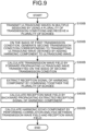
- FIG. 9 is a flowchart for explaining a flow in a process performed by the ultrasound diagnosis apparatus 10 according to the modification example of the second embodiment.
- the transmitter circuitry 9 and the receiver circuitry 11 serving as the transmission/reception unit transmit ultrasound waves to a patient by using the first transmission condition and receive echoes from the patient.
- the ultrasound diagnosis apparatus 10 employs the transmitter circuitry 9 to transmit the ultrasound waves in multiple sessions that are phase-modulated into mutually the same direction by using a plurality of transmission conditions, so that the receiver circuitry 11 receives an echo from the patient with respect to each of the ultrasound waves transmitted in the multiple sessions. More specifically, the transmitter circuitry 9 transmits the ultrasound waves in the multiple sessions by using the plurality of transmission conditions, so that the receiver circuitry 11 receives the plurality of echoes corresponding to the ultrasound waves transmitted in the multiple sessions.
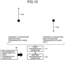
- the transmitter circuitry 9 transmits the ultrasound wave 20a at 0 degrees being the first transmission phase and transmits the ultrasound wave 20b at 180 degrees being the second transmission phase.
- the process in which the transmitter circuitry 9 transmits the ultrasound wave 20a and the ultrasound wave 20b by using the respective transmission conditions, so that the receiver circuitry 11 receives the plurality of echoes is handled as the transmission/reception unit transmitting a single ultrasound wave by using a single first transmission condition 21.
- the processing circuitry 150 generates a second transmission condition corresponding to transmitting an ultrasound wave obtained by adding a harmonic component to the ultrasound wave, on the basis of the first transmission condition. More specifically, by employing the designing function 150h, the processing circuitry 150 generates the second transmission condition 90 by adding the harmonic component 80 to the first transmission condition 21, while handling the process in which the transmission/reception unit transmits the ultrasound waves in the multiple sessions by using the plurality of transmission conditions and receives the plurality of echoes, as the transmission/reception unit transmitting a single ultrasound wave by using the single first transmission condition.
- the processing circuitry 150 may be configured to generate the second transmission condition obtained by adding, to the first transmission condition, a pulse signal in a wide band covering a propagation harmonic component or of a band itself of the propagation harmonic component
- the processing circuitry 150 obtains the transmission wave field 30 by forward propagating the ultrasound wave transmitted on the basis of the second transmission condition, through a forward propagation simulation.
- the processing circuitry 150 may be configured to calculate the transmission wave field 30 on the basis of the second transmission condition 90, for example, by simulating time development of a wave equation, for example, by implementing a simulation method using the FDTD method or an angular spectrum method.
- the processing circuitry 150 extracts a reception signal containing a harmonic component, by combining together the plurality of echoes received at step S100B.
- the processing circuitry 150 may be configured, by employing the second analyzing function 150j, to extract a reception signal containing a second-order harmonic component, by simply adding together the plurality of echoes received at step S100B.
- a reception signal of transducer element containing a second-order harmonic component is generated by adding the reception signals of transducer elements obtained by the ultrasound wave transmissions in two sessions having different transmission phases.
- the processing circuitry 150 may be configured, by employing the second analyzing function 150j, to extract a reception signal containing a third-order harmonic component, by simply adding together the plurality of echoes received at step S100B.
- the processing circuitry 150 calculates the reception wave field 60 by backward propagating the reception signal 50 based on the echoes acquired at step S100.
- the processing circuitry 150 obtains the reception wave field 60, by backward propagating the reception signal 50 extracted at step S350B on the basis of the echoes acquired at step S100.
- the processing circuitry 150 may be configured to obtain the reception wave field 60 by backward propagating the echoes corresponding to the transmission condition, for example, by simulating time development of a wave equation while implementing the FDTD method or implementing a simulation method using an angular spectrum method.
- the processing circuitry 150 After that, at step S500B, by employing the reconstructing function 150g, the processing circuitry 150 generates a harmonic echo component by performing a correlation analysis between the transmission wave field 30 calculated at step S300B and the reception wave field 60 calculated at step S400B.
- the processing circuitry 150 may be configured to perform the correlation analysis by evaluating the right-hand side of Expression (1) between the transmission wave field 30 and the reception wave field 60 and to obtain a resulting image I. Because the resulting image I contains the harmonic echo component, the processing circuitry 150 is able to extract the harmonic component by performing the correlation analysis, while employing the reconstructing function 150g.
- the ultrasound waves in the multiple sessions are combined together at first, before performing the correlation analysis, so as to extract the harmonic component.
- the harmonic imaging capable of extracting the harmonic component and to thus enhance image quality.
- Possible embodiments are not limited to the above examples.
- the example was explained in which, when the forward propagation or backward propagation simulation is performed on the transmission wave fields and the reception wave fields at step S300 and step S400, the simulation is performed without taking non-linear effects of a medium into consideration.
- possible embodiments are not limited to this example.
- a simulation is performed while considering the non-linear effects of the medium.
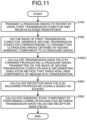
- FIG. 11 is a flowchart for explaining a flow in a process performed by the ultrasound diagnosis apparatus 10 according to the third embodiment.
- the processes other than step S300C are the same as those explained in the first embodiment with reference to FIG. 5 , explanations of those processes will not be repeated.
- the processing circuitry 150 calculates the transmission wave fields 30 by forward propagating the ultrasound waves transmitted on the basis of the second transmission condition, by implementing a simulation method that takes non-linear components of the medium into consideration.
- the processing circuitry 150 may be configured to calculate the transmission wave fields 30 by forward propagating the ultrasound waves transmitted on the basis of the second transmission condition, while implementing a simulation method using a finite element method, for example. By performing the simulation taking the non-linear effects of the medium into consideration, it is expected that image quality will be further enhanced.
- the processing circuitry 150 may obtain the reception wave fields 60 by backward propagating the signals based on the echoes, while implementing a simulation method that takes the non-linear components of the medium into consideration.
- the processing circuitry 150 may be configured to measure, in advance, a non-linear parameter of the medium before performing the process at step S100 and to store the measured non-linear parameter of the medium into the memory 132. After that, at step S300C or step S400, the processing circuitry 150 may be configured to invoke the stored non-linear parameter of the medium from the memory 132 so as to use the parameter for the simulation.
- the processing circuitry 150 may be configured to receive, from the user, a value of the non-linear parameter of the medium via a user interface and to store the received non-linear parameter of the medium into the memory 132. After that, subsequently, at step S300C or step S400, the processing circuitry 150 may be configured to invoke the stored non-linear parameter of the medium from the memory 132 and to use the parameter for the simulation.
- the ultrasound diagnosis apparatus 10 is able to realize further enhancement of image quality, by performing the simulation that takes the non-linear parameter of the medium into consideration.
Landscapes
- Health & Medical Sciences (AREA)
- Life Sciences & Earth Sciences (AREA)
- Engineering & Computer Science (AREA)
- Physics & Mathematics (AREA)
- Molecular Biology (AREA)
- General Health & Medical Sciences (AREA)
- Pathology (AREA)
- Radiology & Medical Imaging (AREA)
- Biophysics (AREA)
- Biomedical Technology (AREA)
- Heart & Thoracic Surgery (AREA)
- Medical Informatics (AREA)
- Veterinary Medicine (AREA)
- Surgery (AREA)
- Animal Behavior & Ethology (AREA)
- Nuclear Medicine, Radiotherapy & Molecular Imaging (AREA)
- Public Health (AREA)
- Radar, Positioning & Navigation (AREA)
- Remote Sensing (AREA)
- Acoustics & Sound (AREA)
- Computer Networks & Wireless Communication (AREA)
- General Physics & Mathematics (AREA)
- Gynecology & Obstetrics (AREA)
- Computer Vision & Pattern Recognition (AREA)
- Nonlinear Science (AREA)
- Ultra Sonic Daignosis Equipment (AREA)
Abstract
Description
- Embodiments described herein relate generally to an ultrasound diagnosis apparatus and an ultrasound diagnosis method.
- In the field of measuring seismic waves, seismic wave interferometry (which may be called a Shot Profile Migration (SPM) or a wave field correlation method) is known. The seismic wave interferometry is a method by which an epicenter position or a reflection plane underground is reconstructed and by which the epicenter position or the like is estimated by performing, for example, a correlation process on a transmission wave field obtained through a forward propagation simulation and a reception wave field obtained from a backward propagation simulation.
- In this situation, since seismic waves and ultrasound waves share the property of being elastic waves, it is considered possible to reconstruct an ultrasound image by applying a method of seismic wave interferometry to an image reconstruction of an ultrasound diagnosis apparatus.
- Widely used in ultrasound diagnosis apparatuses is a so-called harmonic imaging technique by which a harmonic component in an echo is extracted and visualized in an image. Harmonic imaging is important technology as being capable of suppressing echo components from undesired directions. For this reason, when the seismic wave interferometry is applied to an image reconstruction of an ultrasound diagnosis apparatus, it is desirable to be able to carry out harmonic imaging.
- However, when the seismic wave interferometry or the SPM is simply applied to an image reconstruction of an ultrasound diagnosis apparatus, because a harmonic component generated in a propagation process of an ultrasound wave is not taken into consideration, it is not possible to extract and visualize the harmonic component in the echo. Thus, we need to devise a scheme.
- An ultrasound diagnosis apparatus according to at least one aspect of the present disclosure includes transmitter/receiver circuitry and processing circuitry.
- The transmitter/receiver circuitry transmits an ultrasound wave to an examined subject by using a first transmission condition and receives an echo from the examined subject. The processing circuitry generates, on a basis of the first transmission condition, a second transmission condition corresponding to transmitting an ultrasound wave obtained by adding a harmonic component to the ultrasound wave, obtains a transmission wave field by forward propagating the ultrasound wave transmitted on a basis of the second transmission condition, obtains a reception wave field by backward propagating a signal based on the echo, and generates a harmonic echo component by performing a correlation analysis between the transmission wave field and the reception wave field.
- As the second transmission condition, the processing circuitry may generate a transmission condition that has a frequency band of a harmonic component in contrast to the first transmission condition and that is same as the first transmission condition except for the frequency band.
- The transmitter/receiver circuitry may transmit ultrasound waves in multiple sessions that are phase-modulated into a mutually same direction and to receive the echo from the examined subject with respect to each of the ultrasound waves transmitted in the multiple sessions.
- The transmiter/receiver circuitry may transmit ultrasound waves in multiple sessions by using a plurality of first transmission conditions including the first transmission condition and receive a plurality of echoes including the echo.
- The processing circuitry may generate a plurality of second transmission conditions including the second transmission condition and respectively corresponding to the plurality of first transmission conditions, obtain the transmission wave field with respect to each of the plurality of second transmission conditions, obtain the reception wave field with respect to each of the echoes respectively corresponding to the plurality of first transmission conditions, perform the correlation analysis between the transmission wave fields and the reception wave fields with respect to the second transmission conditions respectively corresponding to the first transmission conditions and generate the harmonic echo component on a basis of a result of the correlation analysis.
- The transmitter/receiver circuitry may transmit the ultrasound wave by using a first one of the first transmission condition in a first transmission phase to receive a first echo and transmit the ultrasound wave by using a second one of the first transmission condition in a second transmission phase different from the first transmission phase by 180 degrees to receive a second echo. The processing circuitry may generate a first one of the second transmission condition on a basis of the first one of the first transmission conditionm, generate a second one of the second transmission condition on a basis of the second one of the first transmission condition, obtain a first transmission wave field on a basis of the first one of the second transmission condition, obtain a second transmission wave field on a basis of the second one of the second transmission condition, obtain a first reception wave field on a basis of the first echo and obtain a second reception wave field on a basis of the second echo. The processing circuitry may generate a first signal distribution by performing a correlation analysis between the first transmission wave field and the first reception wave field, generate a second signal distribution by performing a correlation analysis between the second transmission wave field and the second reception wave field, and generate the harmonic echo component on a basis of the first signal distribution and the second signal distribution.
- The processing circuitry may generate the harmonic echo component by performing a subtracting process between the first signal distribution and the second signal distribution.
- The processing circuitry may transmit ultrasound waves in multiple sessions by using a plurality of transmission conditions, receive a plurality of echoes including the echo, handle a process in which the transmitter/receiver circuitry transmits the ultrasound waves in the multiple sessions by using the plurality of transmission conditions and receives the plurality of echoes, as the transmitter/receiver circuitry transmitting a single ultrasound wave by using the first transmission condition being singular. The processing circuitry may generate the second transmission condition on a basis of the first transmission condition, obtain the transmission wave field on a basis of the second transmission condition, obtain the reception wave field on a basis of the plurality of echoes,generate the harmonic echo component by performing the correlation analysis between the transmission wave field and the reception wave field.
- The processing circuitry may extract a reception signal containing a harmonic component by combining the plurality of echoes together, and obtain the reception wave field on a basis of the extracted reception signal.
- The processing circuitry may obtain the transmission wave field by forward propagating the ultrasound wave while implementing a simulation method that takes a non-linear component of a medium into consideration.
- The processing circuitry may obtain the reception wave field by backward propagating the signal based on the echo while implementing a simulation method that takes a non-linear component of a medium into consideration.
- The processing circuitry may implement a simulation method that uses an angular spectrum method.
- An ultrasound diagnosis method according to at least one aspect of the present disclosure includes: transmitting an ultrasound wave to an examined subject by using a first transmission condition and receiving an echo from the examined subject; generating, on a basis of the first transmission condition, a second transmission condition corresponding to transmitting an ultrasound wave obtained by adding a harmonic component to the ultrasound wave; obtaining a transmission wave field by forward propagating the ultrasound wave transmitted on a basis of the second transmission condition; obtaining a reception wave field by backward propagating a signal based on the echo; and generating a harmonic echo component by performing a correlation analysis between the transmission wave field and the reception wave field.
-
-
FIG. 1 is a diagram illustrating an exemplary configuration of an ultrasound diagnosis apparatus according to a first embodiment; -
FIG. 2 is a chart for explaining a process performed by anultrasound diagnosis apparatus 10 according to the first embodiment; -
FIG. 3 is a flowchart for explaining a flow in the process performed by the ultrasound diagnosis apparatus according to the first embodiment; -
FIG. 4 is a chart for explaining a process performed by the ultrasound diagnosis apparatus according to the first embodiment; -
FIG. 5 is a flowchart for explaining a flow in the process performed by the ultrasound diagnosis apparatus according to the first embodiment; -
FIG. 6 is a flowchart for explaining a flow in a process performed by an ultrasound diagnosis apparatus according to a second embodiment; -
FIG. 7 is a chart for explaining the process performed by the ultrasound diagnosis apparatus according to the second embodiment; -
FIG. 8 is another chart for explaining the process performed by the ultrasound diagnosis apparatus according to the second embodiment; -
FIG. 9 is a flowchart for explaining a flow in a process performed by an ultrasound diagnosis apparatus according to a modification example of the second embodiment; -
FIG. 10 is a chart for explaining a process performed by the ultrasound diagnosis apparatus according to the modification example of the second embodiment; and -
FIG. 11 is a flowchart for explaining a flow in a process performed by an ultrasound diagnosis apparatus according to a third embodiment. - To begin with, a configuration of an ultrasound diagnosis apparatus according to a first embodiment will be explained.
FIG. 1 is a block diagram illustrating an exemplary configuration of the ultrasound diagnosis apparatus according to the first embodiment. As illustrated inFIG. 1 , the ultrasound diagnosis apparatus according to the first embodiment includes anultrasound probe 5 and anultrasound diagnosis apparatus 10. Theultrasound diagnosis apparatus 10 includes transmitter circuitry 9,receiver circuitry 11, and a medicalimage processing apparatus 100. - The
ultrasound probe 5 includes a plurality of piezoelectric transducer elements. The plurality of piezoelectric transducer elements are configured to generate an ultrasound wave on the basis of a drive signal supplied from the transmitter circuitry 9 (explained later) included in theultrasound diagnosis apparatus 10. Further, the plurality of piezoelectric transducer elements included in theultrasound probe 5 are configured to receive a reflected wave from an examined subject (hereinafter, "patient") P and convert the received reflected wave into an electrical signal (a reflected-wave signal). Further, theultrasound probe 5 includes a matching layer provided for the piezoelectric transducer elements, a backing member configured to prevent the ultrasound wave from propagating rearward from the piezoelectric transducer elements, and the like. In this situation, theultrasound probe 5 is detachably connected to theultrasound diagnosis apparatus 10. - When the ultrasound wave is transmitted from the
ultrasound probe 5 to the patient P, the transmitted ultrasound wave is repeatedly reflected on a surface of discontinuity of acoustic impedances at a tissue in the body of the patient P, received as the reflected wave by the plurality of piezoelectric transducer elements included in theultrasound probe 5, and converted into the reflected-wave signal. The amplitude of the reflected-wave signal is dependent on the difference between the acoustic impedances on the surface of discontinuity on which the ultrasound wave is reflected. When a transmitted ultrasound pulse is reflected on the surface of a moving blood flow, a cardiac wall, or the like, the reflected-wave signal is, due to the Doppler effect, subject to a frequency shift, depending on a velocity component of the moving members with respect to the ultrasound wave transmission direction. - It should be noted that the embodiment is applicable when the
ultrasound probe 5 is a one-dimensional (1D) array probe configured to two-dimensionally scan the patient P or is a mechanical four-dimensional (4D) probe or a two-dimensional (2D) array probe configured to three-dimensionally scan the patient P. - The
ultrasound diagnosis apparatus 10 is an apparatus configured to generate ultrasound image data on the basis of the reflected-wave signal received from theultrasound probe 5. Theultrasound diagnosis apparatus 10 illustrated inFIG. 1 is capable of generating two-dimensional ultrasound image data on the basis of a two-dimensional reflected-wave signal and capable of generating three-dimensional ultrasound image data on the basis of a three-dimensional reflected-wave signal. However, the embodiment is also applicable when theultrasound diagnosis apparatus 10 is an apparatus exclusively for two-dimensional data. - As illustrated in
FIG. 1 , theultrasound diagnosis apparatus 10 includes the transmitter circuitry 9, thereceiver circuitry 11, and the medicalimage processing apparatus 100. - The transmitter circuitry 9 and the
receiver circuitry 11 are configured to control the ultrasound wave transmission/reception performed by theultrasound probe 5 on the basis of an instruction fromprocessing circuitry 150 including a controllingfunction 150f (explained later). The transmitter circuitry 9 includes a pulse generator, a transmission delay unit, a pulser, and the like and is configured to supply the drive signal to theultrasound probe 5. The pulse generator is configured to repeatedly generate a rate pulse used for forming a transmission ultrasound wave at a prescribed Pulse Repetition Frequency (PRF). Further, the transmission delay unit is configured to apply, to the rate pulses generated by the pulse generator, delay periods that respectively correspond to the piezoelectric transducer elements and are necessary for converging the ultrasound wave generated by theultrasound probe 5 into the form of a beam and determining transmission directionality. Further, the pulser is configured to apply the drive signal (a drive pulse) to theultrasound probe 5, with timing based on the rate pulses. - In other words, the transmission delay unit is configured to arbitrarily adjust transmission directions of the ultrasound wave transmitted from surfaces of the piezoelectric transducer elements, by varying the delay periods applied to the rate pulses. Also, the transmission delay unit is configured to control the position of a convergence point (a transmission focus) in the depth direction of the ultrasound wave transmission, by varying the delay periods applied to the rate pulses.
- Further, the transmitter circuitry 9 has a function capable of instantaneously changing a transmission frequency, transmission drive voltage, and the like, for executing a predetermined scan sequence on the basis of an instruction from the processing circuitry 150 (explained later). In particular, the capability to change the transmission drive voltage is realized by transmitter circuitry of a linear amplifier type capable of instantaneously switching the value thereof or a mechanism configured to electrically switch between a plurality of power source units.
- Further, the
receiver circuitry 11 includes amplifier circuitry, an Analog/Digital (A/D) converter, reception delay circuitry, an adder, quadrature detection circuitry, and the like and is configured to generate a reception signal (reflected-wave data) by performing various types of processes on the reflected-wave signals received from theultrasound probe 5. The amplifier circuitry is configured to amplify the reflected-wave signal with respect to each channel and to perform a gain correction process. The A/D converter is configured to perform an A/D conversion on the gain-corrected reflected-wave signals. The reception delay circuitry is configured to apply, to the digital data, a reception delay period necessary for determining reception directionality. The adder is configured to perform a process of adding together the reflected-wave signals to which the reception delay period was applied by the reception delay circuitry. As a result of the adding process by the adder, reflected components from a direction corresponding to the reception directionality of the reflected-wave signals are emphasized. Further, the quadrature detection circuitry is configured to convert an output signal from the adder into an In-phase signal (an I signal) and a Quadrature-phase signal (a Q signal) in a baseband. After that, the quadrature detection circuitry is configured to transmit the I signal and the Q signal (hereinafter, "IQ signals") to theprocessing circuitry 150, as the reception signal (the reflected-wave data). Alternatively, the quadrature detection circuitry may convert the output signal from the adder into a Radio Frequency (RF) signal, which is then transmitted to theprocessing circuitry 150. The IQ signals and the RF signal serve as reception signals including phase information. - When scanning a two-dimensional region in the patient P, the transmitter circuitry 9 is configured to cause an ultrasound beam for scanning the two-dimensional region to be transmitted from the
ultrasound probe 5. Further, thereceiver circuitry 11 is configured to generate a two-dimensional reception signal from a two-dimensional reflected-wave signal received from theultrasound probe 5. In contrast, when scanning a three-dimensional region in the patient P, the transmitter circuitry 9 is configured to cause an ultrasound beam for scanning the three-dimensional region to be transmitted from theultrasound probe 5. Further, thereceiver circuitry 11 is configured to generate a three-dimensional reception signal from a three-dimensional reflected-wave signal received from theultrasound probe 5. Thereceiver circuitry 11 is configured to generate a reception signal on the basis of the reflected-wave signal and to transmit the generated reception signal to theprocessing circuitry 150. - The transmitter circuitry 9 is configured to cause the
ultrasound probe 5 to transmit the ultrasound beam from a predetermined transmission position (a transmission scanning line). Thereceiver circuitry 11 is configured to receive, from theultrasound probe 5, a signal defined by the reflected wave of the ultrasound beam transmitted by the transmitter circuitry 9, in a predetermined reception position (a reception scanning line). In the situation where a parallel simultaneous reception is not performed, the transmission scanning line and the reception scanning line correspond to the same scanning line. On the contrary, in the situation where a parallel simultaneous reception is performed, when the transmitter circuitry 9 causes theultrasound probe 5 to transmit an ultrasound beam for one session on a single transmission scanning line, thereceiver circuitry 11 is configured to simultaneously receive, via theultrasound probe 5, a signal defined by the reflected wave derived from the ultrasound beam which the transmitter circuitry 9 caused theultrasound probe 5 to transmit, in a plurality of predetermined reception positions (reception scanning lines) as a plurality of reception beams. - The medical
image processing apparatus 100 is connected to the transmitter circuitry 9 and thereceiver circuitry 11 and is configured to process signals received from thereceiver circuitry 11 and to exercise control over the transmitter circuitry 9. The medicalimage processing apparatus 100 includes theprocessing circuitry 150, amemory 132, aninput apparatus 134, and adisplay 135. Theprocessing circuitry 150 includes a B-mode processing function 150a, aDoppler processing function 150b, agenerating function 150c, adisplay controlling function 150d, a receivingfunction 150e, the controllingfunction 150f, a reconstructingfunction 150g, a designingfunction 150h, afirst analyzing function 150i, and asecond analyzing function 150j. - In the embodiment, processing functions executed by the B-mode processing function 150a, the
Doppler processing function 150b, thegenerating function 150c, thedisplay controlling function 150d, the receivingfunction 150e, the controllingfunction 150f, the reconstructingfunction 150g, the designingfunction 150h, thefirst analyzing function 150i, and thesecond analyzing function 150j are stored in thememory 132 in the form of computer-executable programs. Theprocessing circuitry 150 is one or more processors configured to realize the functions corresponding to the programs by reading and executing the programs from thememory 132. In other words, theprocessing circuitry 150 that has read the programs has the functions illustrated within theprocessing circuitry 150 inFIG. 1 . Further, although an example will be explained with reference toFIG. 1 in which the functions of theprocessing circuitry 150 are realized by using the single piece of processing circuitry, it is also acceptable to structure theprocessing circuitry 150 by combining together a plurality of independent processors, so that the functions are realized as a result of the processors executing the programs. In other words, each of the abovementioned functions may be structured as a program, so that a single piece of processing circuitry executes the program. Alternatively, a single piece of processing circuitry may realize two or more of the functions included in theprocessing circuitry 150. In another example, one or more specific functions may be installed in dedicated and independent program executing circuitry. - Further, in
FIG. 1 , theprocessing circuitry 150, the B-mode processing function 150a, theDoppler processing function 150b, thegenerating function 150c, thedisplay controlling function 150d, the receivingfunction 150e, the controllingfunction 150f, the reconstructingfunction 150g, the designingfunction 150h, thefirst analyzing function 150i, and thesecond analyzing function 150j are examples of a B-mode processing unit, a Doppler processing unit, a generating unit, a display controlling unit, a receiving unit, a controlling unit, a reconstructing unit, a designing unit, a first analyzing unit, and a second analyzing unit, respectively. Further, the transmitter circuitry 9 and thereceiver circuitry 11 structure an example of a transmission/reception unit. - The term "processor" used in the above explanations denotes, for example, a Central Processing Unit (CPU), a Graphical Processing Unit (GPU), or circuitry such as an Application Specific Integrated Circuit (ASIC) or a programmable logic device (e.g., a Simple Programmable Logic Device (SPLD), a Complex Programmable Logic Device (CPLD), or a Field Programmable Gate Array (FPGA)). The one or more processors are configured to realize the functions by reading and executing the programs saved in the
memory 132. - Further, instead of having the programs saved in the
memory 132, it is also acceptable to directly incorporate the programs in the circuitry of the one or more processors. In that situation, the one or more processors are configured to realize the functions by reading and executing the programs incorporated in the circuitry thereof. Further, the transmitter circuitry 9, thereceiver circuitry 11, and the like built in theultrasound diagnosis apparatus 10 may be configured by using hardware such as integrated circuitry or may be a program modularized in the form of software. - The
processing circuitry 150 is a processing unit configured to perform various types of signal processing processes on the reception signal received from thereceiver circuitry 11. Theprocessing circuitry 150 includes the B-mode processing function 150a, theDoppler processing function 150b, thegenerating function 150c, thedisplay controlling function 150d, the receivingfunction 150e, the controllingfunction 150f, the reconstructingfunction 150g, the designingfunction 150h, thefirst analyzing function 150i, and thesecond analyzing function 150j. - By employing the B-mode processing function 150a, the
processing circuitry 150 is configured to receive data from thereceiver circuitry 11 and to generate data (B-mode data) in which signal intensities are expressed as levels of brightness, by performing a logarithmic amplifying process, an envelope detecting process, a logarithmic compressing process, and/or the like. - Further, by employing the
Doppler processing function 150b, theprocessing circuitry 150 is configured to generate data (Doppler data) obtained by extracting moving member information such as velocity, dispersion, power, and the like caused by the Doppler effect with respect to multiple points, by performing a frequency analysis to obtain velocity information from the reception signal (the reflected-wave data) received from thereceiver circuitry 11. - The B-mode processing function 150a and the
Doppler processing function 150b illustrated inFIG. 1 are capable of processing both two-dimensional reflected-wave data and three-dimensional reflected-wave data. - By employing the
display controlling function 150d, theprocessing circuitry 150 is configured to exercise control so as to cause thedisplay 135 to display display-purpose ultrasound image data stored in thememory 132. - By employing the receiving
function 150e, theprocessing circuitry 150 is configured to receive various types of operations from a user, via theinput apparatus 134. - By employing the
controlling function 150f, theprocessing circuitry 150 is configured to control all the processes performed by the ultrasound diagnosis apparatus. More specifically, by employing thecontrolling function 150f, theprocessing circuitry 150 is configured to control processes performed by the transmitter circuitry 9, thereceiver circuitry 11, and theprocessing circuitry 150, on the basis of various types of setting requests input by an operator via theinput apparatus 134 and various types of control programs and various types of data read from thememory 132. - By employing the
generating function 150c, theprocessing circuitry 150 is configured to generate the ultrasound image data from the data generated by the B-mode processing function 150a and theDoppler processing function 150b. By employing thegenerating function 150c, theprocessing circuitry 150 is configured to generate two-dimensional B-mode image data in which intensities of the reflected wave are expressed with brightness levels, from two-dimensional B-mode data generated by the B-mode processing function 150a. Further, by employing thegenerating function 150c, theprocessing circuitry 150 is configured to generate two-dimensional Doppler image data expressing the moving member information, from two-dimensional Doppler data generated by theDoppler processing function 150b. The two-dimensional Doppler image data may be velocity image data, dispersion image data, power image data, or image data combining these types of data. - Further, by employing the
generating function 150c, theprocessing circuitry 150 is configured to generate the display-purpose ultrasound image data, by converting (by performing a scan convert process) a scanning line signal sequence from an ultrasound scan into a scanning line signal sequence in a video format used by television, for example. Further, as various types of image processing processes besides the scan convert process, theprocessing circuitry 150 is configured, by employing thegenerating function 150c, to perform, for example, an image processing process (a smoothing process) to re-generate an average brightness value image, an image processing process (an edge enhancement process) that uses a differential filter inside an image, or the like, by using a plurality of image frames resulting from the scan convert process. Also, by employing thegenerating function 150c, theprocessing circuitry 150 is configured to perform various types of rendering processes on volume data, to generate two-dimensional image data for displaying the volume data on thedisplay 135. - Further, the
processing circuitry 150 includes the reconstructingfunction 150g, the designingfunction 150h, thefirst analyzing function 150i, and thesecond analyzing function 150j. These functions will be explained later. - The
memory 132 is configured by using a semiconductor memory element such as a Random Access Memory (RAM) or a flash memory, or a hard disk, an optical disc, or the like. Thememory 132 is a memory configured to store therein data such as display-purpose image data generated by theprocessing circuitry 150. Further, thememory 132 is also capable of storing therein data generated by the B-mode processing function 150a or theDoppler processing function 150b. After a diagnosing process, for example, the operator is able to invoke any of the B-mode data and the Doppler data stored in thememory 132, so that the invoked data serves as the display-purpose ultrasound image data after being routed through theprocessing circuitry 150. Further, thememory 132 is also capable of storing therein the reception signal (the reflected-wave data) output by thereceiver circuitry 11. - In addition, the
memory 132 is configured to store therein, as necessary, control programs for performing the ultrasound wave transmission/reception, image processing processes, and display processes, as well as diagnosis information (e.g., a patient ID, a medical doctor's observations, etc.) and various types of data such as diagnosis protocols and various types of body marks. - The
input apparatus 134 is configured to receive various types of instructions and inputs of information from the operator. For example, theinput apparatus 134 may be pointing equipment such as a mouse or a trackball, selecting equipment such as a mode changing switch, and/or input equipment such as a keyboard. - Under control of the
controlling function 150f and the like, thedisplay 135 is configured to display, among others, a Graphical User Interface (GUI) used for receiving inputs of image taking conditions, images generated by thegenerating function 150c or the like. For example, thedisplay 135 is display equipment such as a liquid display monitor. Thedisplay 135 is an example of a display unit. Thedisplay 135 includes a mouse, a keyboard, a button, a panel switch, a touch command screen, a foot switch, a trackball, a joystick, and/or the like. - Next, a background of the embodiment will be explained.
- In the field of measuring seismic waves, seismic wave interferometry (which may be called a Shot Profile Migration (SPM) or a wave field correlation method) is known. The seismic wave interferometry is a method by which an epicenter position or a reflection plane underground is reconstructed and by which the epicenter position or the like is estimated by performing, for example, a correlation process on a transmission wave field obtained through a forward propagation simulation and a reception wave field obtained through a backward propagation simulation.
- In this situation, since seismic waves and ultrasound waves share the property of being elastic waves, it is considered possible to reconstruct an ultrasound image by applying a method of seismic wave interferometry to an image reconstruction of an ultrasound diagnosis apparatus.
- Widely used in ultrasound diagnosis apparatuses is a so-called harmonic imaging technique by which a harmonic component in an echo is extracted and visualized in an image. Harmonic imaging is important technology as being capable of suppressing echo components from undesired directions. For this reason, when the seismic wave interferometry is applied to an image reconstruction of an ultrasound diagnosis apparatus, it is desirable to be able to carry out harmonic imaging.
- However, when the seismic wave interferometry or the SPM is simply applied to an image reconstruction of an ultrasound diagnosis apparatus, because a harmonic component generated in a propagation process of an ultrasound wave is not taken into consideration, it is not possible to extract and visualize the harmonic component in the echo. Thus, we need to devise a scheme.
Non-Patent Literature 1 proposes an ultrasound image reconstructing method to which seismic wave interferometry is applied. However, a transmission sound field is obtained through a forward propagation simulation, on the basis of a transmission signal from piezoelectric transducer elements, which means that a harmonic component generated in the process of the transmission signal propagating through a living body is not taken into consideration. - The ultrasound diagnosis apparatus of the embodiment is based on the background described above. The ultrasound diagnosis apparatus according to the embodiment includes the transmission/reception unit and the
processing circuitry 150. The transmission/reception unit is configured to transmit an ultrasound wave to a patient by using a first transmission condition and to receive an echo from the patient. By employing the designingfunction 150h, theprocessing circuitry 150 is configured, on the basis of the first transmission condition, to generate a second transmission condition corresponding to transmitting an ultrasound wave obtained by adding a harmonic component to the ultrasound wave. By employing thefirst analyzing function 150i, theprocessing circuitry 150 is configured to obtain a transmission wave field by forward propagating the ultrasound wave transmitted on the basis of the second transmission condition. By employing thesecond analyzing function 150j, theprocessing circuitry 150 is configured to obtain a reception wave field by backward propagating a signal based on the echo. By employing the reconstructingfunction 150g, theprocessing circuitry 150 is configured to generate a harmonic echo component by performing a correlation analysis between the transmission wave field and the reception wave field. - Further, an ultrasound diagnosis method according to the embodiment includes: transmitting an ultrasound wave to a patient by using a first transmission condition and receiving an echo from the patient; generating, on the basis of the first transmission condition, a second transmission condition corresponding to transmitting an ultrasound wave obtained by adding a harmonic component to the ultrasound wave; obtaining a transmission wave field by forward propagating the ultrasound wave transmitted on the basis of the second transmission condition; obtaining a reception wave field by backward propagating a signal based on the echo; and generating a harmonic echo component by performing a correlation analysis between the transmission wave field and the reception wave field.
- As explained above, it is possible to apply the seismic wave interferometry to the harmonic imaging of the ultrasound diagnosis apparatus. For example, it is possible to reconstruct an ultrasound image, while keeping a high capability to suppress echo components from undesired directions, to an extent equal to or higher than capabilities of beam forming technology.
- Processes performed by the
ultrasound diagnosis apparatus 10 according to the first embodiment will be explained, with reference toFIGS. 2 to 5 . - At first, an embodiment in which seismic wave interferometry is simply applied to an ultrasound diagnosing process will be explained, with reference to
FIGS. 2 and3 .FIG. 2 is a schematic chart for explaining a process performed when the seismic interferometry is simply applied to an ultrasound diagnosis apparatus.FIG. 3 is a flowchart indicating the process performed by theultrasound diagnosis apparatus 10 when the seismic interferometry is simply applied to the ultrasound diagnosis apparatus. The flowchart illustrated inFIG. 2 is different from the flowchart inFIG. 4 illustrating processes for performing harmonic imaging in that the process at step S200 (explained later) is not performed and that step S300X is performed inFIG. 2 in place of step S300 inFIG. 4 . - To begin with, at step S100, the transmitter circuitry 9 and the
receiver circuitry 11 serving as the transmission/reception unit transmit an ultrasound wave to a patient by using the first transmission condition and receive an echo from the patient. Typically, theultrasound diagnosis apparatus 10 employs the transmitter circuitry 9 to transmit ultrasound waves in multiple sessions into mutually-different directions, so that thereceiver circuitry 11 receives an echo from the patient with respect to each of the ultrasound waves transmitted in the multiple sessions. For example, as schematically illustrated inFIG. 2 , the transmitter circuitry 9 transmitsultrasound waves receiver circuitry 11 receivesechoes - In this situation, the first transmission condition denotes, typically, a transmission condition such as an amplitude, a phase, a frequency, a transmission aperture, or transmission apodization of the ultrasound wave to be transmitted. In this situation, for example, the transmitter circuitry 9 transmits the
ultrasound wave 20a by usingtransmission condition # 1, transmits theultrasound wave 20b by usingtransmission condition # 2, and transmits theultrasound wave 20c by usingtransmission condition # 3. In this situation,transmission condition # 1,transmission condition # 2, andtransmission condition # 3 are collectively regarded as a single transmission condition and will be handled as afirst transmission condition 20. - Subsequently, at step S300X, by employing the
first analyzing function 150i, theprocessing circuitry 150 calculates transmission wave fields 30, by forward propagating the ultrasound waves transmitted on the basis of the first transmission condition, through a forward propagation simulation. In an example, by employing thefirst analyzing function 150i, theprocessing circuitry 150 may be configured to calculate transmission wave fields f1(x,y,t), f2(x,y,t), and f3(x,y,t) by forward propagating theultrasound wave 20a, theultrasound wave 20b, and theultrasound wave 20c transmitted by usingtransmission condition # 1,transmission condition # 3, andtransmission condition # 3, through the forward propagation simulation. In this situation, x denotes a position coordinate of the ultrasound beam in a direction perpendicular to the advancement direction; y denotes a position coordinate of the ultrasound beam in the advancement direction; and t denotes a time. By employing thefirst analyzing function 150i, theprocessing circuitry 150 may be configured to calculate the transmission wave fields 30, on the basis of the first transmission condition, by simulating time development of a wave equation, for instance. In an example, by employing thefirst analyzing function 150i, theprocessing circuitry 150 may be configured to calculate the transmission wave fields 30 on the basis of the first transmission condition, by implementing a Finite Difference Time Domain (FDTD) method, for instance. In another example, by employing thefirst analyzing function 150i, theprocessing circuitry 150 may be configured to calculate the transmission wave fields 30 on the basis of the first transmission condition, by implementing a simulation method using an angular spectrum method, for instance. - After that, at step S400, by employing the
second analyzing function 150j, theprocessing circuitry 150 calculates reception wave fields 60 by backward propagating the reception signals 50 based on the echoes acquired at step S100. In an example, by employing thesecond analyzing function 150j, theprocessing circuitry 150 may be configured to calculate reception wave fields b1(x,y,t), b2(x,y,t), and b3(x,y,t) from the reception signals r2(x), r2(x) and r3(x), respectively, by simulating time development of a wave equation while implementing the FDTD method, for instance. - Subsequently, at step S500, by employing the reconstructing
function 150g, theprocessing circuitry 150 generates an image by performing a correlation analysis between the transmission wave fields and the reception wave fields. More specifically, an image I is generated by using Expression (1) presented below.
- In Expression (1), n denotes an index for distinguishing the ultrasound waves 20a, 20b, 20c, and so on from one another. N denotes the number of sessions of ultrasound wave transmissions included in a series of ultrasound wave transmissions. The symbol "*" denotes a complex conjugate.
- As explained above, the
processing circuitry 150 is configured to generate the image I, by implementing the SPM method. However, when performing harmonic imaging is taken into consideration, the first transmission condition under which the transmitter circuitry 9 performs the ultrasound wave transmissions is a transmission condition that usually contains no high-order harmonic component. Accordingly, the transmission wave fields 30 obtained through the forward propagation simulation unfortunately contains no high-order harmonic component, either. As a result, even when the correlation analysis is performed between the transmission wave fields 30 and the reception wave fields 60 at step S500, the high-order harmonic component is not sufficiently extracted in the image I. In other words, because the reception waves are processed by matched-filtering based on a transmission frequency band, the frequency band of the reception waves is subject to a band restriction, which suppresses a signal of the high-order harmonic component. - To cope with the circumstances described above, the
ultrasound diagnosis apparatus 10 according to the embodiment is configured, on the basis of the first transmission condition, to generate a second transmission condition corresponding to transmitting an ultrasound wave obtained by adding a harmonic component to the ultrasound wave and to further perform an image generating process based thereon. In an example, by employing the designingfunction 150h, theprocessing circuitry 150 may be configured to generate the second transmission condition obtained by adding, to the first transmission condition, a pulse signal in a wide band covering a propagation harmonic component or of a band itself of the propagation harmonic component and to further perform the image generating process based thereon. With this configuration, it is possible to extract a high-order harmonic component. - These aspects will be explained with reference to
FIGS. 4 and5 .FIG. 4 is a chart for explaining a process performed by theultrasound diagnosis apparatus 10 according to the first embodiment.FIG. 5 is a flowchart for explaining a flow in the process performed by theultrasound diagnosis apparatus 10 according to the first embodiment. - Similarly to the example in
FIG. 2 , to begin with, at step S100, the transmitter circuitry 9 and thereceiver circuitry 11 serving as the transmission/reception unit transmit ultrasound waves to the patient by using the first transmission condition and receive echoes from the patient. Theultrasound diagnosis apparatus 10 employs the transmitter circuitry 9 to transmit ultrasound waves in multiple sessions into mutually-different directions, for example, so that thereceiver circuitry 11 receives an echo from the patient with respect to each of the ultrasound waves transmitted in the multiple sessions. For example, as schematically illustrated inFIG. 4 , the transmitter circuitry 9 transmits the ultrasound waves 20a, 20b, and 20c in the multiple sessions that are phase-modulated into mutually the same direction. - Further, with respect to the ultrasound waves 20a, 20b, and 20c transmitted in the multiple sessions, the
receiver circuitry 11 receivesechoes - In this situation, the first transmission condition denotes, typically, a transmission condition such as an amplitude, a phase, a frequency, a transmission aperture, or transmission apodization of the ultrasound wave to be transmitted. In this situation, for example, the transmitter circuitry 9 transmits the
ultrasound wave 20a by usingtransmission condition # 1, transmits theultrasound wave 20b by usingtransmission condition # 2, and transmits theultrasound wave 20c by usingtransmission condition # 3. Further,transmission condition # 1,transmission condition # 2, andtransmission condition # 3 are collectively regarded as a single transmission condition and will be handled as thefirst transmission condition 20. - Subsequently, at step S200, by employing the designing
function 150h, theprocessing circuitry 150 generates, on the basis of the first transmission condition, a second transmission condition corresponding to transmitting an ultrasound wave obtained by adding a harmonic component to the ultrasound wave. In this situation, the harmonic component is artificially added to the first transmission condition under which the ultrasound waves were actually transmitted, for the purpose of making it possible to extract the high-order harmonic component contained in the reception wave fields, at the time of performing the correlation analysis between the transmission wave fields and the reception wave fields in the process at step S500. In this manner, by employing the designingfunction 150h, theprocessing circuitry 150 is configured to generate asecond transmission condition 90 by artificially adding aharmonic component 80 to thefirst transmission condition 20 under which the ultrasound wave transmissions were actually performed and to thus make it possible to extract the high-order harmonic component at the time of performing the correlation analysis between the transmission wave fields and the reception wave fields. - In this situation, a first mode in which the
processing circuitry 150 adds the harmonic component to the first transmission condition by employing the designingfunction 150h may be, for example, generating thesecond transmission condition 90 by adding, to thefirst transmission condition 20, a transmission condition of a signal in a wide band that widely covers the propagation harmonic component. Further, a second mode in which theprocessing circuitry 150 adds the harmonic component to the first transmission condition by employing the designingfunction 150h may be, for example, generating thesecond transmission condition 90 by adding, to thefirst transmission condition 20, a pulse signal that exhibits a high signal intensity only in the band itself of the propagation harmonic component. In an example, by employing the designingfunction 150h, theprocessing circuitry 150 may be configured to generate, as the second transmission condition, a transmission condition that has a frequency band of a harmonic component in contrast to the first transmission condition and that is the same as the first transmission condition except for the frequency band. In other words, by employing the designingfunction 150h, theprocessing circuitry 150 is configured to generate the second transmission condition having the different frequency from that of the first transmission condition. - However, possible embodiments are not limited to the above example. By employing the designing
function 150h, theprocessing circuitry 150 may be configured to generate a second transmission condition in which, for example, at least one condition selected from among the following is different from that in the first transmission condition: amplitude, phase, transmission aperture, and transmission apodization. In an example, by employing the designingfunction 150h, theprocessing circuitry 150 may be configured to generate a second transmission condition for transmitting an ultrasound wave having a narrower beam than the ultrasound wave transmitted under the first transmission condition, by changing the transmission aperture or the transmission apodization from that in the first transmission condition, so as to reduce impacts of a side lobe, for example. - Further, the configuration of the
processing circuitry 150 configured to employ the designingfunction 150h so as to generate the second transmission condition by changing a condition other than the frequency such as the amplitude, the phase, the transmission aperture, the transmission apodization, or the like, from that in the first transmission condition is similarly applicable also to the second and later embodiments and to modification examples of those embodiments. - Subsequently, at step S300, by employing the
first analyzing function 150i, theprocessing circuitry 150 calculates the transmission wave fields 30, by forward propagating the ultrasound wave transmitted on the basis of the second transmission condition, through a forward propagation simulation. In an example, by employing thefirst analyzing function 150i, theprocessing circuitry 150 may be configured to calculate transmission wave fields f1(x,y,t), f2(x,y,t), and f3(x,y,t) by forward propagating the ultrasound waves transmitted by using thesecond transmission condition 90 obtained by adding theharmonic component 80 totransmission condition # 1,transmission condition # 2, andtransmission condition # 3, through the forward propagation simulation. In this situation, x denotes a position coordinate of the ultrasound beam in a direction perpendicular to the advancement direction; y denotes a position coordinate of the ultrasound beam in the advancement direction; and t denotes a time. By employing thefirst analyzing function 150i, theprocessing circuitry 150 may be configured to calculate the transmission wave fields 30, on the basis of the second transmission condition, by simulating time development of a wave equation, for instance. In an example, by employing thefirst analyzing function 150i, theprocessing circuitry 150 may be configured to calculate the transmission wave fields 30 on the basis of the second transmission condition, by implementing the FDTD method, for instance. In another example, by employing thefirst analyzing function 150i, theprocessing circuitry 150 may be configured to calculate the transmission wave fields 30 on the basis of the second transmission condition, by implementing a simulation method using an angular spectrum method, for instance. - After that, at step S400, by employing the
second analyzing function 150j, theprocessing circuitry 150 calculates the reception wave fields 60 by backward propagating the reception signals 50 based on the echoes acquired at step S100. In an example, by employing thesecond analyzing function 150j, theprocessing circuitry 150 may be configured to calculate reception wave fields b1(x,y,t), b2(x,y,t), and b3(x,y,t) from the reception signals r1(x), r2(x) and r3(x), respectively, by simulating time development of a wave equation while implementing the FDTD method, for instance. In another example, by employing thesecond analyzing function 150j, theprocessing circuitry 150 may be configured to calculate the reception wave fields 60 by backward propagating the reception signals 50, by implementing a simulation method using an angular spectrum method. - Subsequently, at step S500, by employing the reconstructing
function 150g, theprocessing circuitry 150 generates a harmonic echo component by performing a correlation analysis between the transmission wave fields and the reception wave fields. More specifically, by employing the reconstructingfunction 150g, theprocessing circuitry 150 generates an image I containing the harmonic echo component by using Expression (1) presented above. - As explained above, in the first embodiment, by employing the designing
function 150h, theprocessing circuitry 150 is configured, on the basis of the first transmission condition, to generate the second transmission condition obtained by adding the harmonic component to the ultrasound wave and to further perform the correlation analysis based thereon. As a result, it is possible to extract the harmonic component and to thus enhance image quality. - In the first embodiment, the general embodiment was explained in which, at step S100, the transmission/reception unit transmits the one or more ultrasound waves to the patient, by using the first transmission condition. In a second embodiment, an example will be explained further in detail with reference to
FIGS. 6 to 8 in which the transmission/reception unit transmits a plurality of ultrasound waves by implementing a Pulse Inversion method. -
FIG. 6 is a flowchart for explaining a flow in a process performed by theultrasound diagnosis apparatus 10 according to the second embodiment. To begin with, at step S100A, the transmitter circuitry 9 and thereceiver circuitry 11 serving as the transmission/reception unit transmit ultrasound waves to a patient by using the first transmission condition and receive echoes from the patient. Theultrasound diagnosis apparatus 10 employs the transmitter circuitry 9 to transmit the ultrasound waves in multiple sessions that are phase-modulated into mutually the same direction, so that thereceiver circuitry 11 receives an echo from the patient with respect to each of the ultrasound waves transmitted in the multiple sessions. In other words, the transmitter circuitry 9 is configured to transmit the ultrasound waves in the multiple sessions by performing a plurality of first transmissions, so that thereceiver circuitry 11 receives the plurality of echoes. For example, when one set of ultrasound wave transmissions is performed over two transmission sessions, as illustrated inFIG. 7 , the transmitter circuitry 9 transmits theultrasound wave 20a by using a first first transmission condition (a first one of the first transmission condition) 21a by which the ultrasound wave is transmitted in a 0-degree transmission phase being a first transmission phase so that a first echo is received and transmits theultrasound wave 20b by using a second first transmission condition (a second one of the first transmission condition) 21b by which the ultrasound wave is transmitted in a second transmission phase being a transmission phase different from the first transmission phase by 180 degrees so that a second echo is received. - However, possible embodiments are not limited to performing one set of ultrasound wave transmissions over two transmission sessions. For example, it is also acceptable to perform one set of ultrasound wave transmissions over three transmission sessions. In that situation, as illustrated in
FIG. 8 , the transmitter circuitry 9 transmits theultrasound wave 20a by using a firstfirst transmission condition 21a by which the ultrasound wave is transmitted in a 0-degree transmission phase being a first transmission phase so that a first echo is received, also transmits theultrasound wave 20b by using a secondfirst transmission condition 21b by which the ultrasound wave is transmitted in a second transmission phase being a transmission phase different from the first transmission phase by 120 degrees so that a second echo is received, and transmits theultrasound wave 20c by using a thirdfirst transmission condition 21c by which the ultrasound wave is transmitted in a third transmission phase being a transmission phase different from the first transmission phase by 240 degrees so that a third echo is received. - After that, returning to the description of
FIG. 6 , at step S200A, by employing the designingfunction 150h, theprocessing circuitry 150 generates, on the basis of the first transmission conditions, second transmission conditions corresponding to transmitting ultrasound waves obtained by adding a harmonic component to the ultrasound waves. In other words, by employing the designingfunction 150h, theprocessing circuitry 150 is configured to generate a plurality of second transmission conditions respectively corresponding to the plurality of first transmission conditions. - More specifically, as illustrated in
FIG. 7 , when the one set of ultrasound wave transmissions is performed over the two transmission sessions, by employing the designingfunction 150h, theprocessing circuitry 150 generates a first second transmission condition (a first one of the second transmission condition) 90a by adding theharmonic component 80 to the firstfirst transmission condition 21a on the basis of the firstfirst transmission condition 21a and also generates a second second transmission condition (a second one of the second transmission condition) 90b by adding theharmonic component 80 to the secondfirst transmission condition 21b on the basis of the secondfirst transmission condition 21b. Further, as illustrated inFIG. 8 , when the one set of ultrasound wave transmissions is performed over the three transmission sessions, by employing the designingfunction 150h, theprocessing circuitry 150 generates a firstsecond transmission condition 90a by adding theharmonic component 80 to the firstfirst transmission condition 21a on the basis of the firstfirst transmission condition 21a, also generates a secondsecond transmission condition 90b by adding theharmonic component 80 to the secondfirst transmission condition 21b on the basis of the secondfirst transmission condition 21b, and generates a thirdsecond transmission condition 90c by adding theharmonic component 80 to the thirdfirst transmission condition 21c on the basis of the thirdfirst transmission condition 21c. - In this situation, a first mode in which the
processing circuitry 150 adds the harmonic component to the first transmission condition by employing the designingfunction 150h may be, for example, generating thesecond transmission condition 90 by adding, to thefirst transmission condition 20, a transmission condition of a signal in a wide band that widely covers the propagation harmonic component. Further, a second mode in which theprocessing circuitry 150 adds the harmonic component to the first transmission condition by employing the designingfunction 150h may be, for example, generating thesecond transmission condition 90 by adding, to thefirst transmission condition 20, a pulse signal that exhibits a high signal intensity only in the band itself of the propagation harmonic component. In an example, by employing the designingfunction 150h, theprocessing circuitry 150 may be configured to generate, as the second transmission condition, a transmission condition that has a frequency band of a harmonic component in contrast to the first transmission condition and that is the same as the first transmission condition except for the frequency band. Theprocessing circuitry 150 is configured to generate the plurality of second transmission conditions by performing the process described above on each of the plurality of first transmission conditions. By employing the designingfunction 150h, theprocessing circuitry 150 is configured to generate the second transmission conditions in each of which at least one condition selected from among the following is different from that in the first transmission condition: amplitude, phase, frequency, transmission aperture, and transmission apodization. - At step S300A, by employing the
first analyzing function 150i, theprocessing circuitry 150 calculates the transmission wave fields 30 by forward propagating the ultrasound waves transmitted on the basis of the second transmission conditions, through a forward propagation simulation. In other words, by employing thefirst analyzing function 150i, theprocessing circuitry 150 obtains the transmission wave field with respect to each of the plurality of second transmission conditions. For example, by employing thefirst analyzing function 150i, theprocessing circuitry 150 obtains a first transmission wave field by performing a forward propagation simulation on the basis of a first second transmission condition and obtains a second transmission wave field by performing a forward propagation simulation on the basis of a second second transmission condition. By employing thefirst analyzing function 150i, theprocessing circuitry 150 may be configured to calculate the transmission wave fields 30 on the basis of thesecond transmission conditions 90, for example, by simulating time development of a wave equation, for example, by implementing a simulation method using the FDTD method or an angular spectrum method. - After that, at step S400A, by employing the
second analyzing function 150j, theprocessing circuitry 150 calculates the reception wave fields 60 by backward propagating the reception signals 50 based on the echo obtained at step S100. In other words, by employing thesecond analyzing function 150j, theprocessing circuitry 150 obtains the reception wave fields 60 by performing the backward propagation simulation on the echoes respectively corresponding to the plurality of first transmission conditions. More specifically, by employing thesecond analyzing function 150j, theprocessing circuitry 150 obtains a first reception wave field on the basis of a first echo corresponding to a first first transmission conditions and obtains a second reception wave field on the basis of a second echo corresponding to a second first transmission condition. For example, by employing thesecond analyzing function 150j, theprocessing circuitry 150 may be configured to obtain the reception wave fields by backward propagating the echoes corresponding to the transmission conditions, for example, by simulating time development of a wave equation while using the FDTD method or by implementing a simulation method using an angular spectrum method. - Subsequently, at step S500A, by employing the reconstructing
function 150g, theprocessing circuitry 150 performs a correlation analysis by evaluating the right-hand side of Expression (1), for example, between the transmission wave fields and the reception wave fields with respect to the second transmission conditions respectively corresponding to the first transmission conditions. By employing the reconstructingfunction 150g, theprocessing circuitry 150 generates a first signal distribution by performing a correlation analysis on the basis of Expression (1) between a first transmission wave field and a first reception wave field and generates a second signal distribution by performing a correlation analysis on the basis of Expression (1) between a second transmission wave field and a second reception wave field. - After that at step S550A, by employing the reconstructing
function 150g, theprocessing circuitry 150 generates a harmonic echo component on the basis of results of the correlation analyses. For example, by employing the reconstructingfunction 150g, theprocessing circuitry 150 generates the harmonic echo component on the basis of the first signal distribution and the second signal distribution. In this situation, the transmission phase of the transmission ultrasound wave corresponding to the second signal distribution is different, by 180 degrees, from the transmission phase of the transmission ultrasound wave corresponding to the first signal distribution. Accordingly, by employing the reconstructingfunction 150g, theprocessing circuitry 150 generates the harmonic echo component by performing a subtracting process between the first signal distribution and the second signal distribution. It should be noted that, according to a normal pulse inversion method, a harmonic echo component is extracted by adding together signal distributions related to ultrasound wave transmissions. According to the normal pulse inversion method, the harmonic components in reception signals obtained under a first transmission condition and a second transmission condition are in mutually the same phase. However, in the present example, the transmission wave field derived from the transmission phase different by 180 degrees is correlation-processed into the reception wave field. As a result, between the first second transmission condition and the second second transmission condition, the harmonic components in the reception signals are in opposite phases rotated by 180 degrees. For this reason, to extract the harmonic component, the subtracting process is used between the first signal distribution and the second signal distribution. However, possible embodiments are not limited to the subtracting process. For example, by making the transmission phase to be the same between the first first transmission condition and the second first transmission condition and between the first second transmission condition and the second second transmission condition, i.e., by artificially generating, from the transmission conditions applied to the transmitter circuitry 9, transmission conditions that have not only mutually-different frequencies but also mutually-different phases and using the generated conditions as the first second transmission condition and the second second transmission condition, it is possible to extract the harmonic echo component by performing an adding process between the first signal distribution and the second signal distribution. - As explained above, in the second embodiment, the example was explained in which, when the plurality of ultrasound waves are transmitted, the correlation analysis is performed with respect to each of the transmission ultrasound waves, so as to extract the harmonic component on the basis of the obtained plurality of signal distributions. As a result, it is possible to carry out the harmonic imaging capable of extracting the harmonic component and to thus enhance image quality.
- In the second embodiment, the example was explained in which, when the plurality of ultrasound waves are transmitted, the correlation analysis is performed with respect to each of the transmission ultrasound waves, so as to extract the harmonic component on the basis of the obtained plurality of signal distributions. In a modification example of the second embodiment, an example will be explained in which a correlation analysis is performed, while handling ultrasound wave transmissions in multiple sessions as one transmission condition.
-
FIG. 9 is a flowchart for explaining a flow in a process performed by theultrasound diagnosis apparatus 10 according to the modification example of the second embodiment. - To begin with, at step S100B, the transmitter circuitry 9 and the
receiver circuitry 11 serving as the transmission/reception unit transmit ultrasound waves to a patient by using the first transmission condition and receive echoes from the patient. Theultrasound diagnosis apparatus 10 employs the transmitter circuitry 9 to transmit the ultrasound waves in multiple sessions that are phase-modulated into mutually the same direction by using a plurality of transmission conditions, so that thereceiver circuitry 11 receives an echo from the patient with respect to each of the ultrasound waves transmitted in the multiple sessions. More specifically, the transmitter circuitry 9 transmits the ultrasound waves in the multiple sessions by using the plurality of transmission conditions, so that thereceiver circuitry 11 receives the plurality of echoes corresponding to the ultrasound waves transmitted in the multiple sessions. - In this situation, as illustrated in
FIG. 10 , for example, the transmitter circuitry 9 transmits theultrasound wave 20a at 0 degrees being the first transmission phase and transmits theultrasound wave 20b at 180 degrees being the second transmission phase. In this situation, in the modification example of the second embodiment, the process in which the transmitter circuitry 9 transmits theultrasound wave 20a and theultrasound wave 20b by using the respective transmission conditions, so that thereceiver circuitry 11 receives the plurality of echoes is handled as the transmission/reception unit transmitting a single ultrasound wave by using a singlefirst transmission condition 21. - Subsequently, at step S200B, by employing the designing
function 150h, theprocessing circuitry 150 generates a second transmission condition corresponding to transmitting an ultrasound wave obtained by adding a harmonic component to the ultrasound wave, on the basis of the first transmission condition. More specifically, by employing the designingfunction 150h, theprocessing circuitry 150 generates thesecond transmission condition 90 by adding theharmonic component 80 to thefirst transmission condition 21, while handling the process in which the transmission/reception unit transmits the ultrasound waves in the multiple sessions by using the plurality of transmission conditions and receives the plurality of echoes, as the transmission/reception unit transmitting a single ultrasound wave by using the single first transmission condition. In an example, theprocessing circuitry 150 may be configured to generate the second transmission condition obtained by adding, to the first transmission condition, a pulse signal in a wide band covering a propagation harmonic component or of a band itself of the propagation harmonic component - After that, at step S300B, by employing the
first analyzing function 150i, theprocessing circuitry 150 obtains thetransmission wave field 30 by forward propagating the ultrasound wave transmitted on the basis of the second transmission condition, through a forward propagation simulation. By employing thefirst analyzing function 150i, theprocessing circuitry 150 may be configured to calculate thetransmission wave field 30 on the basis of thesecond transmission condition 90, for example, by simulating time development of a wave equation, for example, by implementing a simulation method using the FDTD method or an angular spectrum method. - Further, at step S350B, by employing the
second analyzing function 150j, theprocessing circuitry 150 extracts a reception signal containing a harmonic component, by combining together the plurality of echoes received at step S100B. In an example, when the transmitter circuitry 9 performs ultrasound wave transmissions, by regarding ultrasound wave transmissions in two sessions having transmission phases that are different from each other by 180 degrees as one set, theprocessing circuitry 150 may be configured, by employing thesecond analyzing function 150j, to extract a reception signal containing a second-order harmonic component, by simply adding together the plurality of echoes received at step S100B. More specifically, at step S100B, a reception signal of transducer element containing a second-order harmonic component is generated by adding the reception signals of transducer elements obtained by the ultrasound wave transmissions in two sessions having different transmission phases. In another example, when the transmitter circuitry 9 performs ultrasound wave transmissions, by regarding ultrasound wave transmissions in three sessions having transmission phases that are different from one another by 120 degrees as one set, theprocessing circuitry 150 may be configured, by employing thesecond analyzing function 150j, to extract a reception signal containing a third-order harmonic component, by simply adding together the plurality of echoes received at step S100B. - Subsequently, at step S400B, by employing the
second analyzing function 150j, theprocessing circuitry 150 calculates thereception wave field 60 by backward propagating thereception signal 50 based on the echoes acquired at step S100. In other words, by employing thesecond analyzing function 150j, theprocessing circuitry 150 obtains thereception wave field 60, by backward propagating thereception signal 50 extracted at step S350B on the basis of the echoes acquired at step S100. For example, by employing thesecond analyzing function 150j, theprocessing circuitry 150 may be configured to obtain thereception wave field 60 by backward propagating the echoes corresponding to the transmission condition, for example, by simulating time development of a wave equation while implementing the FDTD method or implementing a simulation method using an angular spectrum method. - After that, at step S500B, by employing the reconstructing
function 150g, theprocessing circuitry 150 generates a harmonic echo component by performing a correlation analysis between thetransmission wave field 30 calculated at step S300B and thereception wave field 60 calculated at step S400B. In an example, by employing the reconstructingfunction 150g, theprocessing circuitry 150 may be configured to perform the correlation analysis by evaluating the right-hand side of Expression (1) between thetransmission wave field 30 and thereception wave field 60 and to obtain a resulting image I. Because the resulting image I contains the harmonic echo component, theprocessing circuitry 150 is able to extract the harmonic component by performing the correlation analysis, while employing the reconstructingfunction 150g. - As explained above, in the modification example of the second embodiment, when the plurality of ultrasound waves are transmitted, the ultrasound waves in the multiple sessions are combined together at first, before performing the correlation analysis, so as to extract the harmonic component. With this arrangement, it is possible to carry out the harmonic imaging capable of extracting the harmonic component and to thus enhance image quality.
- Possible embodiments are not limited to the above examples. In the first embodiment, the example was explained in which, when the forward propagation or backward propagation simulation is performed on the transmission wave fields and the reception wave fields at step S300 and step S400, the simulation is performed without taking non-linear effects of a medium into consideration. However, possible embodiments are not limited to this example. In a third embodiment, an example will be explained in which a simulation is performed while considering the non-linear effects of the medium.
-
FIG. 11 is a flowchart for explaining a flow in a process performed by theultrasound diagnosis apparatus 10 according to the third embodiment. In this situation, because the processes other than step S300C are the same as those explained in the first embodiment with reference toFIG. 5 , explanations of those processes will not be repeated. - At step S300C, by employing the
first analyzing function 150i, theprocessing circuitry 150 calculates the transmission wave fields 30 by forward propagating the ultrasound waves transmitted on the basis of the second transmission condition, by implementing a simulation method that takes non-linear components of the medium into consideration. In an example, by employing thefirst analyzing function 150i, theprocessing circuitry 150 may be configured to calculate the transmission wave fields 30 by forward propagating the ultrasound waves transmitted on the basis of the second transmission condition, while implementing a simulation method using a finite element method, for example. By performing the simulation taking the non-linear effects of the medium into consideration, it is expected that image quality will be further enhanced. - Similarly, at step S400, by employing the
second analyzing function 150j, theprocessing circuitry 150 may obtain the reception wave fields 60 by backward propagating the signals based on the echoes, while implementing a simulation method that takes the non-linear components of the medium into consideration. - Further, by employing the designing
function 150h, theprocessing circuitry 150 may be configured to measure, in advance, a non-linear parameter of the medium before performing the process at step S100 and to store the measured non-linear parameter of the medium into thememory 132. After that, at step S300C or step S400, theprocessing circuitry 150 may be configured to invoke the stored non-linear parameter of the medium from thememory 132 so as to use the parameter for the simulation. - In yet another example, by employing the receiving
function 150e, theprocessing circuitry 150 may be configured to receive, from the user, a value of the non-linear parameter of the medium via a user interface and to store the received non-linear parameter of the medium into thememory 132. After that, subsequently, at step S300C or step S400, theprocessing circuitry 150 may be configured to invoke the stored non-linear parameter of the medium from thememory 132 and to use the parameter for the simulation. - As explained above, the
ultrasound diagnosis apparatus 10 according to the third embodiment is able to realize further enhancement of image quality, by performing the simulation that takes the non-linear parameter of the medium into consideration. - According to at least one aspect of the embodiments described above, it is possible to enhance image quality.
- While certain embodiments have been described, these embodiments have been presented by way of example only, and are not intended to limit the scope of the inventions. Indeed, the novel embodiments described herein may be embodied in a variety of other forms; furthermore, various omissions, substitutions and changes in the form of the embodiments described herein may be made without departing from the spirit of the inventions. The accompanying claims and their equivalents are intended to cover such forms or modifications as would fall within the scope and spirit of the inventions.
Claims (12)
- An ultrasound diagnosis apparatus comprising:transmitter/receiver circuitry (9, 11) configured to transmit an ultrasound wave to an examined subject by using a first transmission condition and to receive an echo from the examined subject; andprocessing circuitry (150) configuredto generate, on a basis of the first transmission condition, a second transmission condition corresponding to transmitting an ultrasound wave obtained by adding a harmonic component to the ultrasound wave,to obtain a transmission wave field by forward propagating the ultrasound wave transmitted on a basis of the second transmission condition,to obtain a reception wave field by backward propagating a signal based on the echo, andto generate a harmonic echo component by performing a correlation analysis between the transmission wave field and the reception wave field.
- The ultrasound diagnosis apparatus according to claim 1, wherein, as the second transmission condition, the processing circuitry (150) is configured to generate a transmission condition that has a frequency band of a harmonic component in contrast to the first transmission condition and that is same as the first transmission condition except for the frequency band.
- The ultrasound diagnosis apparatus according to claim 1 or 2, wherein the transmitter/receiver circuitry (9, 11) is configured to transmit ultrasound waves in multiple sessions that are phase-modulated into a mutually same direction and to receive the echo from the examined subject with respect to each of the ultrasound waves transmitted in the multiple sessions.
- The ultrasound diagnosis apparatus according to any one of claims 1 to 3, whereinthe transmiter/receiver circuitry is configured to transmit ultrasound waves in multiple sessions by using a plurality of first transmission conditions including the first transmission condition and to receive a plurality of echoes including the echo,the processing circuitry (150) is configured to generate a plurality of second transmission conditions including the second transmission condition and respectively corresponding to the plurality of first transmission conditions,the processing circuitry (150) is configured to obtain the transmission wave field with respect to each of the plurality of second transmission conditions,the processing circuitry (150) is configured to obtain the reception wave field with respect to each of the echoes respectively corresponding to the plurality of first transmission conditions, andthe processing circuitry (150) is configured to perform the correlation analysis between the transmission wave fields and the reception wave fields with respect to the second transmission conditions respectively corresponding to the first transmission conditions and to generate the harmonic echo component on a basis of a result of the correlation analysis.
- The ultrasound diagnosis apparatus according to claim 4, whereinthe transmitter/receiver circuitry (9, 11) is configured to transmit the ultrasound wave by using a first one of the first transmission condition in a first transmission phase to receive a first echo and configured to transmit the ultrasound wave by using a second one of the first transmission condition in a second transmission phase different from the first transmission phase by 180 degrees to receive a second echo,the processing circuitry (150) is configured to generate a first one of the second transmission condition on a basis of the first one of the first transmission condition and to generate a second one of the second transmission condition on a basis of the second one of the first transmission condition,the processing circuitry (150) is configured to obtain a first transmission wave field on a basis of the first one of the second transmission condition,the processing circuitry (150) is configured to obtain a second transmission wave field on a basis of the second one of the second transmission condition,the processing circuitry (150) is configured to obtain a first reception wave field on a basis of the first echo and to obtain a second reception wave field on a basis of the second echo, andthe processing circuitry (150) is configured to generate a first signal distribution by performing a correlation analysis between the first transmission wave field and the first reception wave field, to generate a second signal distribution by performing a correlation analysis between the second transmission wave field and the second reception wave field, and to generate the harmonic echo component on a basis of the first signal distribution and the second signal distribution.
- The ultrasound diagnosis apparatus according to claim 5, wherein the processing circuitry (150) is configured to generate the harmonic echo component by performing a subtracting process between the first signal distribution and the second signal distribution.
- The ultrasound diagnosis apparatus according to claim 1, whereinthe processing circuitry (150) is configured to transmit ultrasound waves in multiple sessions by using a plurality of transmission conditions and to receive a plurality of echoes including the echo,the processing circuitry (150) is configured to handle a process in which the transmitter/receiver circuitry (9, 11) transmits the ultrasound waves in the multiple sessions by using the plurality of transmission conditions and receives the plurality of echoes, as the transmitter/receiver circuitry (9, 11) transmitting a single ultrasound wave by using the first transmission condition being singular,the processing circuitry (150) is configured to generate the second transmission condition on a basis of the first transmission condition,the processing circuitry (150) is configured to obtain the transmission wave field on a basis of the second transmission condition,the processing circuitry (150) is configured to obtain the reception wave field on a basis of the plurality of echoes, andthe processing circuitry (150) is configured to generate the harmonic echo component by performing the correlation analysis between the transmission wave field and the reception wave field.
- The ultrasound diagnosis apparatus according to claim 7, whereinthe processing circuitry (150) is configured to extract a reception signal containing a harmonic component by combining the plurality of echoes together, andthe processing circuitry (150) is configured to obtain the reception wave field on a basis of the extracted reception signal.
- The ultrasound diagnosis apparatus according to any one of claims 1 to 8, wherein the processing circuitry (150) is configured to obtain the transmission wave field by forward propagating the ultrasound wave while implementing a simulation method that takes a non-linear component of a medium into consideration.
- The ultrasound diagnosis apparatus according to any one of claims 1 to 8, wherein the processing circuitry (150) is configured to obtain the reception wave field by backward propagating the signal based on the echo while implementing a simulation method that takes a non-linear component of a medium into consideration.
- The ultrasound diagnosis apparatus according to any oee of claims 1 to 10, wherein the processing circuitry (150) is configured to implement a simulation method that uses an angular spectrum method.
- An ultrasound diagnosis method comprising:transmitting an ultrasound wave to an examined subject by using a first transmission condition and receiving an echo from the examined subject;generating, on a basis of the first transmission condition, a second transmission condition corresponding to transmitting an ultrasound wave obtained by adding a harmonic component to the ultrasound wave;obtaining a transmission wave field by forward propagating the ultrasound wave transmitted on a basis of the second transmission condition;obtaining a reception wave field by backward propagating a signal based on the echo; andgenerating a harmonic echo component by performing a correlation analysis between the transmission wave field and the reception wave field.
Applications Claiming Priority (1)
| Application Number | Priority Date | Filing Date | Title |
|---|---|---|---|
| JP2023138397A JP2025032890A (en) | 2023-08-28 | 2023-08-28 | Ultrasound diagnostic device and ultrasound diagnostic method |
Publications (2)
| Publication Number | Publication Date |
|---|---|
| EP4517375A1 true EP4517375A1 (en) | 2025-03-05 |
| EP4517375B1 EP4517375B1 (en) | 2026-04-22 |
Family
ID=92583062
Family Applications (1)
| Application Number | Title | Priority Date | Filing Date |
|---|---|---|---|
| EP24196682.9A Active EP4517375B1 (en) | 2023-08-28 | 2024-08-27 | Ultrasound diagnosis apparatus and ultrasound diagnosis method |
Country Status (3)
| Country | Link |
|---|---|
| US (1) | US20250072864A1 (en) |
| EP (1) | EP4517375B1 (en) |
| JP (1) | JP2025032890A (en) |
-
2023
- 2023-08-28 JP JP2023138397A patent/JP2025032890A/en active Pending
-
2024
- 2024-08-27 US US18/815,934 patent/US20250072864A1/en active Pending
- 2024-08-27 EP EP24196682.9A patent/EP4517375B1/en active Active
Non-Patent Citations (2)
| Title |
|---|
| LIN FANGLUE ET AL: "Ultrasound contrast imaging: influence of scatterer motion in multi-pulse techniques", IEEE TRANSACTIONS ON ULTRASONICS, FERROELECTRICS, AND FREQUENCY CONTROL, IEEE, USA, vol. 60, no. 10, October 2013 (2013-10-01), XP011527578, ISSN: 0885-3010, [retrieved on 20130919], DOI: 10.1109/TUFFC.2013.2797 * |
| YANG XIONGBIN ET AL: "A reverse time migration-based multistep angular spectrum approach for ultrasonic imaging of specimens with irregular surfaces", ULTRASONICS, IPC SCIENCE AND TECHNOLOGY PRESS LTD. GUILDFORD, GB, vol. 108, 31 July 2020 (2020-07-31), XP086267015, ISSN: 0041-624X, [retrieved on 20200731], DOI: 10.1016/J.ULTRAS.2020.106233 * |
Also Published As
| Publication number | Publication date |
|---|---|
| EP4517375B1 (en) | 2026-04-22 |
| JP2025032890A (en) | 2025-03-12 |
| US20250072864A1 (en) | 2025-03-06 |
Similar Documents
| Publication | Publication Date | Title |
|---|---|---|
| JP7387249B2 (en) | Ultrasound diagnostic equipment, medical image processing equipment, and medical image processing programs | |
| US10564281B2 (en) | Ultrasonography apparatus and ultrasonic imaging method | |
| US11568535B2 (en) | Medical image processing apparatus, ultrasound diagnosis apparatus, and trained model generating method | |
| JP2017093913A (en) | Ultrasonic diagnostic device, signal processing device and analysis program | |
| US20150320398A1 (en) | Ultrasonic diagnostic apparatus and control method | |
| US11076831B2 (en) | Ultrasound diagnosis apparatus, signal processing apparatus, and signal processing method | |
| JP2015213673A (en) | Ultrasonic diagnostic apparatus | |
| JP6733478B2 (en) | Ultrasonic signal processing device, ultrasonic signal processing method, and ultrasonic diagnostic device | |
| US11717269B2 (en) | Ultrasound diagnosis apparatus, medical image processing apparatus, and storage medium | |
| US11583241B2 (en) | Ultrasound diagnosis apparatus, medical image processing apparatus, and medical image processing method | |
| US20150327840A1 (en) | Ultrasonic diagnostic device and correction method | |
| US11564662B2 (en) | Ultrasound diagnosis apparatus, medical image processing apparatus, and medical image processing method | |
| US20170252007A1 (en) | Ultrasonic diagnostic apparatus | |
| JP7827411B2 (en) | Ultrasound diagnostic equipment and medical image processing equipment | |
| JP7832409B2 (en) | Ultrasound diagnostic apparatus, processing method, and program | |
| EP4517375B1 (en) | Ultrasound diagnosis apparatus and ultrasound diagnosis method | |
| JP6288998B2 (en) | Ultrasonic diagnostic apparatus and ultrasonic imaging program | |
| EP4109132A1 (en) | Ultrasound diagnostic apparatus and extraction method | |
| US20260029520A1 (en) | Ultrasonic diagnostic apparatus, method of signal processing, and non-transitory computer readable medium | |
| US20240260942A1 (en) | Ultrasound diagnosis apparatus and ultrasound signal generating method | |
| JP7804470B2 (en) | Ultrasound diagnostic device, ultrasound diagnostic method, and ultrasound diagnostic program | |
| US12059305B2 (en) | Ultrasonic diagnostic device, medical image processing device, and medical image processing method | |
| JP2023104734A (en) | Ultrasound diagnostic device and image processing device |
Legal Events
| Date | Code | Title | Description |
|---|---|---|---|
| PUAI | Public reference made under article 153(3) epc to a published international application that has entered the european phase |
Free format text: ORIGINAL CODE: 0009012 |
|
| STAA | Information on the status of an ep patent application or granted ep patent |
Free format text: STATUS: REQUEST FOR EXAMINATION WAS MADE |
|
| 17P | Request for examination filed |
Effective date: 20240827 |
|
| AK | Designated contracting states |
Kind code of ref document: A1 Designated state(s): AL AT BE BG CH CY CZ DE DK EE ES FI FR GB GR HR HU IE IS IT LI LT LU LV MC ME MK MT NL NO PL PT RO RS SE SI SK SM TR |
|
| GRAP | Despatch of communication of intention to grant a patent |
Free format text: ORIGINAL CODE: EPIDOSNIGR1 |
|
| STAA | Information on the status of an ep patent application or granted ep patent |
Free format text: STATUS: GRANT OF PATENT IS INTENDED |
|
| RIC1 | Information provided on ipc code assigned before grant |
Ipc: G01S 7/52 20060101AFI20251103BHEP Ipc: G01S 15/89 20060101ALI20251103BHEP Ipc: A61B 8/00 20060101ALI20251103BHEP Ipc: A61B 8/15 20060101ALI20251103BHEP |
|
| INTG | Intention to grant announced |
Effective date: 20251112 |
|
| GRAS | Grant fee paid |
Free format text: ORIGINAL CODE: EPIDOSNIGR3 |
|
| GRAA | (expected) grant |
Free format text: ORIGINAL CODE: 0009210 |
|
| STAA | Information on the status of an ep patent application or granted ep patent |
Free format text: STATUS: THE PATENT HAS BEEN GRANTED |
|
| AK | Designated contracting states |
Kind code of ref document: B1 Designated state(s): AL AT BE BG CH CY CZ DE DK EE ES FI FR GB GR HR HU IE IS IT LI LT LU LV MC ME MK MT NL NO PL PT RO RS SE SI SK SM TR |
|
| REG | Reference to a national code |
Ref country code: CH Ref legal event code: F10 Free format text: ST27 STATUS EVENT CODE: U-0-0-F10-F00 (AS PROVIDED BY THE NATIONAL OFFICE) Effective date: 20260422 Ref country code: GB Ref legal event code: FG4D |
|
| REG | Reference to a national code |
Ref country code: DE Ref legal event code: R096 Ref document number: 602024004151 Country of ref document: DE |