EP4517368A1 - A method for estimating current positions of sensor elements in an array sensor, a computer program product, a computer-readable storage medium, as well as an array sensor - Google Patents
A method for estimating current positions of sensor elements in an array sensor, a computer program product, a computer-readable storage medium, as well as an array sensor Download PDFInfo
- Publication number
- EP4517368A1 EP4517368A1 EP23193743.4A EP23193743A EP4517368A1 EP 4517368 A1 EP4517368 A1 EP 4517368A1 EP 23193743 A EP23193743 A EP 23193743A EP 4517368 A1 EP4517368 A1 EP 4517368A1
- Authority
- EP
- European Patent Office
- Prior art keywords
- sensor
- positions
- array sensor
- array
- electronic computing
- Prior art date
- Legal status (The legal status is an assumption and is not a legal conclusion. Google has not performed a legal analysis and makes no representation as to the accuracy of the status listed.)
- Pending
Links
Images

Classifications
-
- G—PHYSICS
- G01—MEASURING; TESTING
- G01S—RADIO DIRECTION-FINDING; RADIO NAVIGATION; DETERMINING DISTANCE OR VELOCITY BY USE OF RADIO WAVES; LOCATING OR PRESENCE-DETECTING BY USE OF THE REFLECTION OR RERADIATION OF RADIO WAVES; ANALOGOUS ARRANGEMENTS USING OTHER WAVES
- G01S13/00—Systems using the reflection or reradiation of radio waves, e.g. radar systems; Analogous systems using reflection or reradiation of waves whose nature or wavelength is irrelevant or unspecified
- G01S13/87—Combinations of radar systems, e.g. primary radar and secondary radar
- G01S13/876—Combination of several spaced transponders or reflectors of known location for determining the position of a receiver
-
- G—PHYSICS
- G01—MEASURING; TESTING
- G01S—RADIO DIRECTION-FINDING; RADIO NAVIGATION; DETERMINING DISTANCE OR VELOCITY BY USE OF RADIO WAVES; LOCATING OR PRESENCE-DETECTING BY USE OF THE REFLECTION OR RERADIATION OF RADIO WAVES; ANALOGOUS ARRANGEMENTS USING OTHER WAVES
- G01S13/00—Systems using the reflection or reradiation of radio waves, e.g. radar systems; Analogous systems using reflection or reradiation of waves whose nature or wavelength is irrelevant or unspecified
- G01S13/003—Bistatic radar systems; Multistatic radar systems
-
- G—PHYSICS
- G01—MEASURING; TESTING
- G01S—RADIO DIRECTION-FINDING; RADIO NAVIGATION; DETERMINING DISTANCE OR VELOCITY BY USE OF RADIO WAVES; LOCATING OR PRESENCE-DETECTING BY USE OF THE REFLECTION OR RERADIATION OF RADIO WAVES; ANALOGOUS ARRANGEMENTS USING OTHER WAVES
- G01S13/00—Systems using the reflection or reradiation of radio waves, e.g. radar systems; Analogous systems using reflection or reradiation of waves whose nature or wavelength is irrelevant or unspecified
- G01S13/02—Systems using reflection of radio waves, e.g. primary radar systems; Analogous systems
- G01S13/06—Systems determining position data of a target
-
- B—PERFORMING OPERATIONS; TRANSPORTING
- B60—VEHICLES IN GENERAL
- B60R—VEHICLES, VEHICLE FITTINGS, OR VEHICLE PARTS, NOT OTHERWISE PROVIDED FOR
- B60R11/00—Arrangements for holding or mounting articles, not otherwise provided for
-
- G—PHYSICS
- G01—MEASURING; TESTING
- G01S—RADIO DIRECTION-FINDING; RADIO NAVIGATION; DETERMINING DISTANCE OR VELOCITY BY USE OF RADIO WAVES; LOCATING OR PRESENCE-DETECTING BY USE OF THE REFLECTION OR RERADIATION OF RADIO WAVES; ANALOGOUS ARRANGEMENTS USING OTHER WAVES
- G01S13/00—Systems using the reflection or reradiation of radio waves, e.g. radar systems; Analogous systems using reflection or reradiation of waves whose nature or wavelength is irrelevant or unspecified
- G01S13/87—Combinations of radar systems, e.g. primary radar and secondary radar
-
- G—PHYSICS
- G01—MEASURING; TESTING
- G01S—RADIO DIRECTION-FINDING; RADIO NAVIGATION; DETERMINING DISTANCE OR VELOCITY BY USE OF RADIO WAVES; LOCATING OR PRESENCE-DETECTING BY USE OF THE REFLECTION OR RERADIATION OF RADIO WAVES; ANALOGOUS ARRANGEMENTS USING OTHER WAVES
- G01S13/00—Systems using the reflection or reradiation of radio waves, e.g. radar systems; Analogous systems using reflection or reradiation of waves whose nature or wavelength is irrelevant or unspecified
- G01S13/88—Radar or analogous systems specially adapted for specific applications
- G01S13/93—Radar or analogous systems specially adapted for specific applications for anti-collision purposes
- G01S13/931—Radar or analogous systems specially adapted for specific applications for anti-collision purposes of land vehicles
-
- G—PHYSICS
- G01—MEASURING; TESTING
- G01S—RADIO DIRECTION-FINDING; RADIO NAVIGATION; DETERMINING DISTANCE OR VELOCITY BY USE OF RADIO WAVES; LOCATING OR PRESENCE-DETECTING BY USE OF THE REFLECTION OR RERADIATION OF RADIO WAVES; ANALOGOUS ARRANGEMENTS USING OTHER WAVES
- G01S3/00—Direction-finders for determining the direction from which infrasonic, sonic, ultrasonic or electromagnetic waves, or particle emission, not having a directional significance, are being received
- G01S3/02—Direction-finders for determining the direction from which infrasonic, sonic, ultrasonic or electromagnetic waves, or particle emission, not having a directional significance, are being received using radio waves
- G01S3/14—Systems for determining direction or deviation from predetermined direction
-
- G—PHYSICS
- G01—MEASURING; TESTING
- G01S—RADIO DIRECTION-FINDING; RADIO NAVIGATION; DETERMINING DISTANCE OR VELOCITY BY USE OF RADIO WAVES; LOCATING OR PRESENCE-DETECTING BY USE OF THE REFLECTION OR RERADIATION OF RADIO WAVES; ANALOGOUS ARRANGEMENTS USING OTHER WAVES
- G01S5/00—Position-fixing by co-ordinating two or more direction or position line determinations; Position-fixing by co-ordinating two or more distance determinations
- G01S5/02—Position-fixing by co-ordinating two or more direction or position line determinations; Position-fixing by co-ordinating two or more distance determinations using radio waves
- G01S5/0284—Relative positioning
- G01S5/0289—Relative positioning of multiple transceivers, e.g. in ad hoc networks
-
- G—PHYSICS
- G01—MEASURING; TESTING
- G01S—RADIO DIRECTION-FINDING; RADIO NAVIGATION; DETERMINING DISTANCE OR VELOCITY BY USE OF RADIO WAVES; LOCATING OR PRESENCE-DETECTING BY USE OF THE REFLECTION OR RERADIATION OF RADIO WAVES; ANALOGOUS ARRANGEMENTS USING OTHER WAVES
- G01S7/00—Details of systems according to groups G01S13/00, G01S15/00, G01S17/00
- G01S7/02—Details of systems according to groups G01S13/00, G01S15/00, G01S17/00 of systems according to group G01S13/00
- G01S7/40—Means for monitoring or calibrating
-
- G—PHYSICS
- G01—MEASURING; TESTING
- G01S—RADIO DIRECTION-FINDING; RADIO NAVIGATION; DETERMINING DISTANCE OR VELOCITY BY USE OF RADIO WAVES; LOCATING OR PRESENCE-DETECTING BY USE OF THE REFLECTION OR RERADIATION OF RADIO WAVES; ANALOGOUS ARRANGEMENTS USING OTHER WAVES
- G01S7/00—Details of systems according to groups G01S13/00, G01S15/00, G01S17/00
- G01S7/02—Details of systems according to groups G01S13/00, G01S15/00, G01S17/00 of systems according to group G01S13/00
- G01S7/40—Means for monitoring or calibrating
- G01S7/4052—Means for monitoring or calibrating by simulation of echoes
- G01S7/4082—Means for monitoring or calibrating by simulation of echoes using externally generated reference signals, e.g. via remote reflector or transponder
- G01S7/4086—Means for monitoring or calibrating by simulation of echoes using externally generated reference signals, e.g. via remote reflector or transponder in a calibrating environment, e.g. anechoic chamber
-
- H—ELECTRICITY
- H04—ELECTRIC COMMUNICATION TECHNIQUE
- H04B—TRANSMISSION
- H04B17/00—Monitoring; Testing
- H04B17/20—Monitoring; Testing of receivers
- H04B17/27—Monitoring; Testing of receivers for locating or positioning the transmitter
-
- B—PERFORMING OPERATIONS; TRANSPORTING
- B60—VEHICLES IN GENERAL
- B60R—VEHICLES, VEHICLE FITTINGS, OR VEHICLE PARTS, NOT OTHERWISE PROVIDED FOR
- B60R11/00—Arrangements for holding or mounting articles, not otherwise provided for
- B60R2011/0001—Arrangements for holding or mounting articles, not otherwise provided for characterised by position
- B60R2011/004—Arrangements for holding or mounting articles, not otherwise provided for characterised by position outside the vehicle
-
- G—PHYSICS
- G01—MEASURING; TESTING
- G01S—RADIO DIRECTION-FINDING; RADIO NAVIGATION; DETERMINING DISTANCE OR VELOCITY BY USE OF RADIO WAVES; LOCATING OR PRESENCE-DETECTING BY USE OF THE REFLECTION OR RERADIATION OF RADIO WAVES; ANALOGOUS ARRANGEMENTS USING OTHER WAVES
- G01S13/00—Systems using the reflection or reradiation of radio waves, e.g. radar systems; Analogous systems using reflection or reradiation of waves whose nature or wavelength is irrelevant or unspecified
- G01S13/88—Radar or analogous systems specially adapted for specific applications
- G01S13/93—Radar or analogous systems specially adapted for specific applications for anti-collision purposes
- G01S13/931—Radar or analogous systems specially adapted for specific applications for anti-collision purposes of land vehicles
- G01S2013/9327—Sensor installation details
- G01S2013/93271—Sensor installation details in the front of the vehicles
-
- G—PHYSICS
- G01—MEASURING; TESTING
- G01S—RADIO DIRECTION-FINDING; RADIO NAVIGATION; DETERMINING DISTANCE OR VELOCITY BY USE OF RADIO WAVES; LOCATING OR PRESENCE-DETECTING BY USE OF THE REFLECTION OR RERADIATION OF RADIO WAVES; ANALOGOUS ARRANGEMENTS USING OTHER WAVES
- G01S13/00—Systems using the reflection or reradiation of radio waves, e.g. radar systems; Analogous systems using reflection or reradiation of waves whose nature or wavelength is irrelevant or unspecified
- G01S13/88—Radar or analogous systems specially adapted for specific applications
- G01S13/93—Radar or analogous systems specially adapted for specific applications for anti-collision purposes
- G01S13/931—Radar or analogous systems specially adapted for specific applications for anti-collision purposes of land vehicles
- G01S2013/9327—Sensor installation details
- G01S2013/93275—Sensor installation details in the bumper area
Definitions
- the present invention relates to a method for estimating current positions of sensor elements in an array sensor according to the pending claim 1. Furthermore, the present invention relates to a computer program product, a computer-readable storage medium as well as to an array sensor.
- Estimating the current positions of sensor elements in an array sensor is a well-known problem in the state of the art.
- GP 2002 344 223 A1 provides a method of determining the position of an array antenna element for improving its output performance.
- An array antenna unit is equipped with a STAP controller and is provided with a first function which is obtained, by adding up the expectations of the squared absolute values of auto-correlation functions of the general impulse response of all the desired waves; a second function is obtained by adding up the expectations of the squared absolute values of cross-correlation functions between the general impulse response of all the desired waves and the general impulse response of all the interference waves; a third function is the sum of the first and second function, and a fourth function has a factor that is the positions (n-1) other antennas relatively determined with the position of an antenna element as reference; and an antenna position designing unit determines the position of n antenna elements, by calculating the positions of the other (n-1) antenna elements which reduces the fourth function to be minimal.
- US 11, 005, 580 B2 discloses an array antenna calibration method and device, which is used for calibrating an array antenna in real time in an open calibration environment.
- the method includes: determining, on the basis of a preset direction angle of each preset beam direction, an initial beam weight vector matrix of an array antenna to be calibrated, and emitting, by a test antenna in a standard beam direction, a first calibration signal to the array antenna to be calibrated; determining, on the basis of the first calibration signal received by each channel of the array antenna to be calibrated, a magnitude-phase arrow between the first calibration signal received by a center channel and a first calibration signal received by each channel; and using the magnitude-phase arrow to calibrate the initial beam weight vector matrix, so as to obtain a compensation beam weight vector matrix.
- an antenna array comprise a surface comprising a replicated pattern of conductive tracks, the tracks defining a plurality of ports.
- a plurality of antenna are located at ports distributed about the surface.
- a plurality of radiative transceivers are electrically connected to a respective antenna.
- a plurality of reference transceivers are electrically connected to a non-radiative impedance located at a respective port so that each reference transceiver is surrounded by a group of antenna and electrically coupled to the group of antenna by the tracks. At least one antenna from the at least one group of antenna belongs to one other group of antenna.
- Calibration circuitry includes a controller associated with each reference transceiver, each controller being arranged to transmit a calibration signal through an associated reference transceiver and to receive and store a received calibration signal from a selected transceiver for the group of antenna coupled to the reference transceiver. Each controller is further arranged to receive and store a calibration signal from the selected transceiver for the group of antenna coupled to the reference transceiver.
- the calibration circuitry further includes for each other transceiver for the group of antenna, circuitry for adjusting the phase and amplitude of signals transmitted and received by the radiative transceivers relative to the stored calibration signals for the selected radiative transceiver.
- One aspect of the invention relates to a method for estimating current positions of sensor elements in an array sensor.
- Initial position estimates of the sensor elements are provided by an electronic computing device of the array sensor.
- a sensor signal is transmitted in the surroundings of the array sensor by a transmitting device of the array sensor and a reflected sensor signal is received by a receiving device of the array sensor, wherein the sensor signal is reflected on at least one calibration target in the surroundings.
- At least a direction of arrival of the reflected signal is determined by the electronic computing device.
- a virtual position of each of the sensor elements is estimated analytically depending on the direction of arrival by the electronic computing device based on a criterion of smallest residuum.
- the current positions are estimated depending on the virtual positions and the initial position estimates by the electronic computing device.
- determining at least a direction of arrival of a reflected signal by the electronic computing device may be provided by the electronic computing device itself or other target localization devices/techniques.
- the target of the invention is to estimate three-dimensional antenna positions and complex channel imbalances for measured range/Doppler/channel maps, for example at least with four disjoint calibration targets.
- a d-dimensional position estimate requires a number of d targets, plus one additional target, if also channel imbalances are to be estimated.
- Targets can be in near-field, but the location should be ideally "known". The closer to the array, the more precise the range need to be known. In the far-field, only the direction of arrival (DoA) information suffices. In principle, an estimate of target location information can be obtained even with the sensor itself.
- the signal to noise ratio (SNR) is sufficiently high such that noise does not disturb the phases significantly.
- the method is analytical, in the sense that no costly numerical optimization is required.
- the derivation of the method assumes that the data samples are noise-free. It can of course still be applied to noisy data, although performance is presumable more sensitive to noise than other methods.
- At least four reflected signals from at least four calibration targets are received. It is also possible, that less than four calibration targets may be used.
- a d-dimensional position estimate requires d targets, plus one additional, if also channel imbalances are to be estimated. Therefore, if for example a two-dimensional position estimate is computed, just two calibration targets are used. If the two-dimensional estimation is used and also the channel imbalances are used, at least three calibration targets are used. For the three-dimensional estimation three targets have to be used. If also the channel imbalances are estimated, four calibration targets are used. Therefore a precise estimation of the current positions is provided.
- a distance to the at least one calibration target is provided and the virtual position is additionally determined depending on the provided distance.
- the distance can be provided externally. Therefore, depending on the distance, a precise estimating of the current sensor positions is realized.
- a channel imbalance of the antenna is determined.
- channel imbalances of the array sensor are determined. Therefore, with the provided method, also the channel imbalances can be estimated and therefore counter measures for the channel imbalances can be determined.
- the channel imbalance is determined by using a singular value decomposition algorithm. Therefore, a precise method is provided for determining the channel imbalance.
- the channel imbalance is determined by using a higher-order singular value decomposition algorithm. Therefore, a precise method is provided for determining the channel imbalance.
- the initial positions are nominal positions. Therefore, a normalization of the data may be provided. Therefore, the normalization is performed to decouple the estimation of positions an imbalances.
- the estimated virtual positions are bootstrapped as the initial positions. Therefore, a further calculating/estimating of the positions can be realized, in particular with a higher precision.
- the received signal is compensated concerning a phase contribution due to geometry from the received signal. Therefore, a more precise estimating of the current sensor positions is provided.
- the sensor device is provided as a radar device and/or a communication device. Therefore, the sensor device can be used as a radar device and/or communication device. This has the advantage, that as well as for communicating, for example with a satellite, and/or for capturing surroundings of a motor vehicle the sensor device can be used.
- the method is a computer-implemented method. Therefore, another aspect of the invention relates to a computer program product comprising program code means for performing a method according to the preceding aspect.
- the invention relates to a computer-readable storage medium comprising at least the computer program product according to the preceding aspect.
- a still further aspect of the invention relates to an array sensor, in particular to a sensor device and/or communication device for a motor vehicle or any kind of vehicle, comprising at least one transmitting device, one receiving device, and one electronic computing device, wherein the array sensor, in particular the sensor device and/or communication device is configured for performing a method according to the preceding aspect.
- the method is performed by the sensor device and/or communication device.
- a still further aspect of the invention relates to a motor vehicle comprising at least the sensor device and/or communication device according to the preceding aspect.
- the sensor device and/or communication device may comprise means for performing the method.
- the invention also includes the control device/electronic computing device for the motor vehicle.
- the control device may comprise a data processing device or a processor device adapted to perform an embodiment of the method according to the invention.
- the processor device may comprise at least one microprocessor and/or at least one microcontroller and/or at least one FPGA (field programmable gate array) and/or at least one DSP (digital signal processor).
- a CPU Central Processing Unit
- a GPU Graphics Unit
- NPU Neurological Processing Unit
- the processor device may have program code which is set up to perform the embodiment of the method according to the invention when executed by the processor device.
- the program code may be stored in a data memory of the processor device.
- the processor device may be based, for example, on at least one circuit board and/or on at least one SoC (system on chip).
- the motor vehicle according to the invention is preferably designed as a motor vehicle, in particular as a passenger car or truck, or as a passenger bus or motorcycle.
- the invention also comprises a computer-readable storage medium comprising program code which, when executed by a computer or computer network, causes the computer or computer network to execute an embodiment of the method according to the invention.
- the storage medium may be provided at least in part as a non-volatile data storage (e.g., as a flash memory and/or as an SSD - solid state drive) and/or at least in part as a volatile data storage (e.g., as a RAM - random access memory).
- the storage medium may be arranged in the computer or computer network. However, the storage medium may also be operated, for example, as a so-called appstore server and/or cloud server on the Internet.
- a processor circuit with, for example, at least one microprocessor may be provided by the computer or computer network.
- the program code may be provided as binary code and/or as assembly code and/or as source code of a programming language (e.g. C) and/or as program script (e.g. Python).
- the invention also encompasses combinations of the features of the described embodiments.
- the invention also encompasses realizations each having a combination of the features of more than one of the described embodiments, provided that the embodiments have not been described as mutually exclusive.
- Fig. 1 shows a schematic top view according to an embodiment of a motor vehicle 1.
- the motor vehicle 1 may comprise an assistance system 2 for an at least in part assisted operation of the motor vehicle 1.
- the motor vehicle 1 may comprise an array sensor 3, in particular for the assistance system 2.
- the array sensor 3 may be configured as a sensing device 4, as shown in Fig. 1 and/or as a communication device 5.
- the array sensor 3 may comprise at least one transmitting device 6, one receiving device 7, and one electronic computing device 8.
- the array sensor 3 may comprise a first sensor element 10, a second sensor element 11, a third sensor element 12, as well as a fourth sensor element 13. It is obvious for a person skilled in the art, that the array sensor 3 may comprise less than four sensor elements 10, 11, 12, 13, or more than four sensor elements 10, 11, 12, 13.
- a sensor signal 14 is transmitted in surroundings 15 of the array sensor 3 by the transmitting device 6 and reflected sensor signals 16 are received by the receiving device 7, wherein the sensor signal 14 is reflected on at least one calibration target 17, 18, 19, 20.
- At least a direction of arrival of the reflected signal 16 is determined by the electronic computing device 8.
- a virtual position of each of the sensor elements 10, 11, 12, 13 is estimated depending on the direction of arrival by the electronic computing device 8 based on a criterion of a smallest residuum.
- the current positions 9 are estimated depending on the virtual positions and the initial positions estimated by the electronic computing device 8.
- Fig. 1 shows a first calibration target 17, a second calibration target 18, a third calibration target 19, as well as a fourth calibration target 20. Additionally a distance to the at least one calibration target 17, 18, 19, 20 is provided and the virtual position is additionally determined depending on the provided distance.
- the channel imbalance is determined by using a singular value decomposition algorithm.
- the channel imbalance is determined by using a higher-order singular value decomposition.
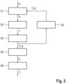
- Fig. 2 shows a schematic flow chart according to an embodiment of the method.
- Fig. 2 shows in a first step S1 that data is normalized.
- a second step S2 virtual positions are estimated.
- a third step S3 the real positions are estimated.
- the estimated positions are bootstrapped to the first step S1.
- a fifth step S5 is performed, wherein the data is compensated.
- a sixth step S6 the channel imbalances are estimated.
- Fig. 2 shows that in the first step S1 an element-wise division by data from selected reference channel and reference targets is performed, and a compensation of unwanted terms with "fudge factor" is performed.
- a second step S2 the virtual positions are estimated. An analytic solution for each hypothesis of unwrapping that could have resulted in the measured phases is performed. The virtual positions are estimated based on the criterion of the smallest residuum.
- the third step S3 the real positions are estimated. In particular a pseudo-inversion and a fix origin from prior knowledge of the sensor elements positions is used.
- the fourth step S4 is performed, wherein the current estimates are bootstrapped as prior knowledge.
- the fifth step S5 the data is compensated. Using the estimated positions and potentially accepted target model to eliminate the phase contribution due to geometry from the data is provided.
- the sixth step S6 the channel imbalance is estimated. Applying SVD or HOSVD
- step S1 normalization of the data is provided.
- Radar operates at wavelength ⁇ .
- the ⁇ can be estimated rather accurately even with only modest prior knowledge of antenna positions and target locations. For far-field targets, the RMSE converges to zero.
- f t ⁇ 2 ⁇ u H t ⁇ 2 + r ⁇ 2 ⁇ u H r ⁇ 2 ⁇ 2 t ⁇ 0 2 ⁇ u H t ⁇ 0 2 t ⁇ + r ⁇ 2
- f is set to zero for those channels if it would otherwise exceed some maximum value.
- f is set to zero for those channels if it would otherwise exceed some maximum value.
- the virtual positions are estimated.
- ⁇ : ⁇ 2 ⁇ ⁇ 2 ⁇ ⁇ ⁇ 4 , ⁇ 4 ,
- the selection of fudge factors could be guided by an appropriate robustness criterion.
- the real positions are estimated. Once that estimates V ⁇ ⁇ R 3 ⁇ N Tx N Rx have been found for all virtual positions, it remains to convert them back into estimates of real positions of T ⁇ T ⁇ ⁇ R 3 ⁇ N Tx and R ⁇ R ⁇ ⁇ R 3 ⁇ N Rx .
- Adding some more rows to M is convenient for numerical stability and to fix another degree of freedom (note that shifting Rx and Tx arrays against each other leaves virtual positions unchanged). They can be used to set e.g. the array centers according to prior knowledge.
- the optional fourth step S4 may be performed, wherein bootstrapping with current estimates as prior knowledge is performed. Given now new current estimates of antenna positions T ⁇ , R ⁇ , the steps S1 to S3 can be repeated so far with these hopefully improved estimates as prior knowledge.
- Compensating data is performed, in particular by using the estimated positions and potentially extended target model.
- estimating channel imbalances can be performed by using SVD or HOSVD to find rank-1 of approximation.
- SVD singular value decomposition
Landscapes
- Engineering & Computer Science (AREA)
- Radar, Positioning & Navigation (AREA)
- Remote Sensing (AREA)
- Physics & Mathematics (AREA)
- General Physics & Mathematics (AREA)
- Computer Networks & Wireless Communication (AREA)
- Electromagnetism (AREA)
- Signal Processing (AREA)
- Mechanical Engineering (AREA)
- Radar Systems Or Details Thereof (AREA)
Abstract
The present invention relates to a method for estimating current positions (9) of sensor elements (10, 11, 12, 13) in an array sensor (3), comprising the steps of: Providing initial position estimates of the sensor elements (10, 11, 12, 13) by an electronic computing device (8) of the array sensor (3); Transmitting a sensor signal (14) in surroundings (15) of the array sensor (3) by a transmitting device (6) of the array sensor (3) and receiving a reflected sensor signal (16) by a receiving device (7) of the array sensor (3), wherein the sensor signal (14) is reflected on at least one calibration target (17, 16, 18, 19) in the surroundings (15); Determining at least a direction of arrival of the reflected signal (16) by the electronic computing device (8); Estimating a virtual position of each of the sensor elements (10, 11, 12, 13) analytically depending on the direction of arrival by the electronic computing device (8) based on a criterion of smallest residuum; and Estimating the current positions (9) depending on the virtual positions and the initial position estimates by the electronic computing device (8). Furthermore the invention relates to a computer program product, a computer-readable storage medium, as well as to an array sensor (3.)
Description
- The present invention relates to a method for estimating current positions of sensor elements in an array sensor according to the pending claim 1. Furthermore, the present invention relates to a computer program product, a computer-readable storage medium as well as to an array sensor.
- Estimating the current positions of sensor elements in an array sensor is a well-known problem in the state of the art. In particular, for example for at least in part automated motor vehicles, it is important to know the sensor position very precise, in order to capture the surroundings in an improved manner and therefore controlling the motor vehicle very safe in the surroundings.
-
GP 2002 344 223 A1 provides a method of determining the position of an array antenna element for improving its output performance. An array antenna unit is equipped with a STAP controller and is provided with a first function which is obtained, by adding up the expectations of the squared absolute values of auto-correlation functions of the general impulse response of all the desired waves; a second function is obtained by adding up the expectations of the squared absolute values of cross-correlation functions between the general impulse response of all the desired waves and the general impulse response of all the interference waves; a third function is the sum of the first and second function, and a fourth function has a factor that is the positions (n-1) other antennas relatively determined with the position of an antenna element as reference; and an antenna position designing unit determines the position of n antenna elements, by calculating the positions of the other (n-1) antenna elements which reduces the fourth function to be minimal. -
US 11, 005, 580 B2 - According to the
US 7, 714, 776 B2 an antenna array comprise a surface comprising a replicated pattern of conductive tracks, the tracks defining a plurality of ports. A plurality of antenna are located at ports distributed about the surface. A plurality of radiative transceivers are electrically connected to a respective antenna. A plurality of reference transceivers are electrically connected to a non-radiative impedance located at a respective port so that each reference transceiver is surrounded by a group of antenna and electrically coupled to the group of antenna by the tracks. At least one antenna from the at least one group of antenna belongs to one other group of antenna. Calibration circuitry includes a controller associated with each reference transceiver, each controller being arranged to transmit a calibration signal through an associated reference transceiver and to receive and store a received calibration signal from a selected transceiver for the group of antenna coupled to the reference transceiver. Each controller is further arranged to receive and store a calibration signal from the selected transceiver for the group of antenna coupled to the reference transceiver. The calibration circuitry further includes for each other transceiver for the group of antenna, circuitry for adjusting the phase and amplitude of signals transmitted and received by the radiative transceivers relative to the stored calibration signals for the selected radiative transceiver. - It is an object of the present invention to provide a method, a computer program product, a computer-readable storage medium as well as an array sensor, by which an improved estimating of current positions of sensor elements in the array sensor is provided.
- This object is solved by a method, a computer program product, a computer-readable storage medium as well as an array sensor according to the independent claims. Advantageous embodiments are presented in the dependent claims.
- One aspect of the invention relates to a method for estimating current positions of sensor elements in an array sensor. Initial position estimates of the sensor elements are provided by an electronic computing device of the array sensor. A sensor signal is transmitted in the surroundings of the array sensor by a transmitting device of the array sensor and a reflected sensor signal is received by a receiving device of the array sensor, wherein the sensor signal is reflected on at least one calibration target in the surroundings. At least a direction of arrival of the reflected signal is determined by the electronic computing device. A virtual position of each of the sensor elements is estimated analytically depending on the direction of arrival by the electronic computing device based on a criterion of smallest residuum. The current positions are estimated depending on the virtual positions and the initial position estimates by the electronic computing device.
- Therefore, an analytical way for estimating current positions of sensor elements is provided. In particular, determining at least a direction of arrival of a reflected signal by the electronic computing device may be provided by the electronic computing device itself or other target localization devices/techniques.
- In particular, the target of the invention is to estimate three-dimensional antenna positions and complex channel imbalances for measured range/Doppler/channel maps, for example at least with four disjoint calibration targets. In particular, when restricted to a subspace, a d-dimensional position estimate requires a number of d targets, plus one additional target, if also channel imbalances are to be estimated.
- Targets can be in near-field, but the location should be ideally "known". The closer to the array, the more precise the range need to be known. In the far-field, only the direction of arrival (DoA) information suffices. In principle, an estimate of target location information can be obtained even with the sensor itself. The signal to noise ratio (SNR) is sufficiently high such that noise does not disturb the phases significantly.
- Prior knowledge on antenna positions is required for successful outcome, ideally with accuracy of 3D error better than half of the operating wave length lambda/2.
- The range of sets of peak shifts due to cable delays can also be compensated, but this task is independent from estimation of antenna position and channel imbalances. In a dynamic scene with moving platforms, range migration over ramps have to be compensated for first.
- In particular, the method is analytical, in the sense that no costly numerical optimization is required.
- In particular in the near-field case, it relies on some choice of "fudge factors", which are determined from prior knowledge of antenna positions and target locations. They are used to pre-transform the data in a way that eliminates unwanted terms in the bistatic range's tailor series, which prevent analytic treatment.
- The derivation of the method assumes that the data samples are noise-free. It can of course still be applied to noisy data, although performance is presumable more sensitive to noise than other methods.
- In particular, at least four reflected signals from at least four calibration targets are received. It is also possible, that less than four calibration targets may be used. In particular, a d-dimensional position estimate requires d targets, plus one additional, if also channel imbalances are to be estimated. Therefore, if for example a two-dimensional position estimate is computed, just two calibration targets are used. If the two-dimensional estimation is used and also the channel imbalances are used, at least three calibration targets are used. For the three-dimensional estimation three targets have to be used. If also the channel imbalances are estimated, four calibration targets are used. Therefore a precise estimation of the current positions is provided.
- According to another embodiment additionally a distance to the at least one calibration target is provided and the virtual position is additionally determined depending on the provided distance. In particular, the distance can be provided externally. Therefore, depending on the distance, a precise estimating of the current sensor positions is realized.
- In another embodiment additionally depending on the estimated current positions a channel imbalance of the antenna is determined. In particular depending on the estimated current positions, also channel imbalances of the array sensor are determined. Therefore, with the provided method, also the channel imbalances can be estimated and therefore counter measures for the channel imbalances can be determined.
- In another embodiment the channel imbalance is determined by using a singular value decomposition algorithm. Therefore, a precise method is provided for determining the channel imbalance.
- In another embodiment the channel imbalance is determined by using a higher-order singular value decomposition algorithm. Therefore, a precise method is provided for determining the channel imbalance.
- According to another embodiment the initial positions are nominal positions. Therefore, a normalization of the data may be provided. Therefore, the normalization is performed to decouple the estimation of positions an imbalances.
- In another embodiment the estimated virtual positions are bootstrapped as the initial positions. Therefore, a further calculating/estimating of the positions can be realized, in particular with a higher precision.
- According to another embodiment the received signal is compensated concerning a phase contribution due to geometry from the received signal. Therefore, a more precise estimating of the current sensor positions is provided.
- In another embodiment the sensor device is provided as a radar device and/or a communication device. Therefore, the sensor device can be used as a radar device and/or communication device. This has the advantage, that as well as for communicating, for example with a satellite, and/or for capturing surroundings of a motor vehicle the sensor device can be used.
- In particular, the method is a computer-implemented method. Therefore, another aspect of the invention relates to a computer program product comprising program code means for performing a method according to the preceding aspect.
- Furthermore, the invention relates to a computer-readable storage medium comprising at least the computer program product according to the preceding aspect.
- A still further aspect of the invention relates to an array sensor, in particular to a sensor device and/or communication device for a motor vehicle or any kind of vehicle, comprising at least one transmitting device, one receiving device, and one electronic computing device, wherein the array sensor, in particular the sensor device and/or communication device is configured for performing a method according to the preceding aspect.
- In particular, the method is performed by the sensor device and/or communication device.
- A still further aspect of the invention relates to a motor vehicle comprising at least the sensor device and/or communication device according to the preceding aspect.
- Advantageous embodiments of the method are to be regarded as advantageous embodiments of the computer program product, the computer-readable storage medium, the sensor device and/or communication device, and the motor vehicle. Therefore, the sensor device and/or communication device as well as the motor vehicle may comprise means for performing the method.
- The invention also includes the control device/electronic computing device for the motor vehicle. The control device may comprise a data processing device or a processor device adapted to perform an embodiment of the method according to the invention. For this purpose, the processor device may comprise at least one microprocessor and/or at least one microcontroller and/or at least one FPGA (field programmable gate array) and/or at least one DSP (digital signal processor). In particular, a CPU (Central Processing Unit), a GPU (Graphical Processing Unit) or an NPU (Neural Processing Unit) can be used as the microprocessor in each case. Furthermore, the processor device may have program code which is set up to perform the embodiment of the method according to the invention when executed by the processor device. The program code may be stored in a data memory of the processor device. The processor device may be based, for example, on at least one circuit board and/or on at least one SoC (system on chip).
- The motor vehicle according to the invention is preferably designed as a motor vehicle, in particular as a passenger car or truck, or as a passenger bus or motorcycle.
- As a further solution, the invention also comprises a computer-readable storage medium comprising program code which, when executed by a computer or computer network, causes the computer or computer network to execute an embodiment of the method according to the invention. The storage medium may be provided at least in part as a non-volatile data storage (e.g., as a flash memory and/or as an SSD - solid state drive) and/or at least in part as a volatile data storage (e.g., as a RAM - random access memory). The storage medium may be arranged in the computer or computer network. However, the storage medium may also be operated, for example, as a so-called appstore server and/or cloud server on the Internet. A processor circuit with, for example, at least one microprocessor may be provided by the computer or computer network. The program code may be provided as binary code and/or as assembly code and/or as source code of a programming language (e.g. C) and/or as program script (e.g. Python).
- The invention also encompasses combinations of the features of the described embodiments. Thus, the invention also encompasses realizations each having a combination of the features of more than one of the described embodiments, provided that the embodiments have not been described as mutually exclusive.
- The drawings show in:
-
Fig. 1 a schematic top view according to an embodiment of a motor vehicle comprising an array sensor; and -
Fig. 2 a schematic flow chart according to an embodiment of the method. - In the figures the same elements are comprising the same reference signs.
-
Fig. 1 shows a schematic top view according to an embodiment of a motor vehicle 1. The motor vehicle 1 may comprise anassistance system 2 for an at least in part assisted operation of the motor vehicle 1. Furthermore, the motor vehicle 1 may comprise anarray sensor 3, in particular for theassistance system 2. Thearray sensor 3 may be configured as a sensing device 4, as shown inFig. 1 and/or as acommunication device 5. Thearray sensor 3 may comprise at least onetransmitting device 6, onereceiving device 7, and oneelectronic computing device 8. - According to an embodiment of the method initial position estimate 9 of a
sensor element array sensor 3 are provided by theelectronic computing device 8. As shown inFig. 1 , thearray sensor 3 may comprise afirst sensor element 10, asecond sensor element 11, athird sensor element 12, as well as afourth sensor element 13. It is obvious for a person skilled in the art, that thearray sensor 3 may comprise less than foursensor elements sensor elements - A
sensor signal 14 is transmitted insurroundings 15 of thearray sensor 3 by the transmittingdevice 6 and reflected sensor signals 16 are received by the receivingdevice 7, wherein thesensor signal 14 is reflected on at least onecalibration target - At least a direction of arrival of the reflected signal 16 is determined by the
electronic computing device 8. A virtual position of each of thesensor elements electronic computing device 8 based on a criterion of a smallest residuum. The current positions 9 are estimated depending on the virtual positions and the initial positions estimated by theelectronic computing device 8. - As shown in
Fig. 1 , at least four reflected sensor signals 16 from at least fourcalibration targets Fig. 1 shows afirst calibration target 17, asecond calibration target 18, athird calibration target 19, as well as afourth calibration target 20. Additionally a distance to the at least onecalibration target - Furthermore, additionally depending on the estimated current positions 9 a channel imbalance of the
sensor element - In another embodiment the channel imbalance is determined by using a singular value decomposition algorithm. Alternatively, the channel imbalance is determined by using a higher-order singular value decomposition.
-
Fig. 2 shows a schematic flow chart according to an embodiment of the method. In particular,Fig. 2 shows in a first step S1 that data is normalized. In a second step S2 virtual positions are estimated. In a third step S3 the real positions are estimated. In a fourth step S4 the estimated positions are bootstrapped to the first step S1. Coming from the third step S3 a fifth step S5 is performed, wherein the data is compensated. In a sixth step S6 the channel imbalances are estimated. - In particular,
Fig. 2 shows that in the first step S1 an element-wise division by data from selected reference channel and reference targets is performed, and a compensation of unwanted terms with "fudge factor" is performed. In a second step S2 the virtual positions are estimated. An analytic solution for each hypothesis of unwrapping that could have resulted in the measured phases is performed. The virtual positions are estimated based on the criterion of the smallest residuum. In the third step S3 the real positions are estimated. In particular a pseudo-inversion and a fix origin from prior knowledge of the sensor elements positions is used. Optional the fourth step S4 is performed, wherein the current estimates are bootstrapped as prior knowledge. In the fifth step S5 the data is compensated. Using the estimated positions and potentially accepted target model to eliminate the phase contribution due to geometry from the data is provided. In the sixth step S6 the channel imbalance is estimated. Applying SVD or HOSVD - Now, the steps S1 to S6 are presented in more detail. According to the first step S1 normalization of the data is provided.
- An array consists of Tx m = 1, ... , NTx and Rx n = 1, ... , NRx with (3D Cartesian) positions

- Data model for range/Doppler snapshots: For Cartesian target location pk ,


- Select a virtual 'reference channel' (wlog, l = 0), which will also serve as coordinate origin v 0 = 0 in the following.
- Divide now element-wise by the signal in the reference channel and compensate with the following (estimated) residual phases


- Here a 'fudge factors' f is introduced, which is usually set to


- On the choice of fudge factors. There is probably more than one good rationale to set the fudge factors. Here, minimizing the (first order terms of) the RMSE under Gaussian perturbations of the ideal Δ and its practically available estimate, i.e.,


- The result for f is independent of the error
variance 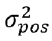

- Here,

- Note that the Δ can be estimated rather accurately even with only modest prior knowledge of antenna positions and target locations. For far-field targets, the RMSE converges to zero.
- Another reasonable choice of fudge factors is

- It is based on the observation that

- Also very similar performance for the two choices can be observed, the former having possibly a slight edge over the latter in the near-field.
- To avoid numerical instabilities for virtual channels near the origin (other than the reference channel), in one possible embodiment f is set to zero for those channels if it would otherwise exceed some maximum value. (Possible criterion:

- Choose further a 'reference target' (wlog, k = 0) and divide element-wise along the channel dimension to eliminate the channel imbalances


- This step can be skipped in case that channel imbalances have already been compensated, i.e. γl = const. All the formulas remain valid with the obvious modifications, e.g., f 0 = 0, u 0 = 0, K -> K + 1.
- In the second step S2 the virtual positions are estimated. For the normalized phases of zkl , defined as
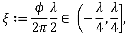
- There is the equation (indices l can be dropped since the problem is decoupled in the virtual positions vl ),

- In vector notation, introduce


- Derivation of analytic solution for (Eq.1). (Can be skipped on first reading.)
- Now let Q = (n, Q̃) ∈ SO(3). Recall that by definition of orthogonal matrices, we have I 3 =

- With


- Stated equivalently,


- Apparently


- In summary, the sought-after position estimate is given by the formula

- In the case K = 3, every ζ gives a valid solution (within the limits of prior knowledge). In the case K > 3, the residiuum

- How exactly additional calibration targets increase the unambiguous cell depends on the precise location and seems difficult to describe.
- In any case, one has to search over a grid in ζ. Prior knowledge on vp gives an idea for a grid center

- The method is 'exact' in the far-field case

- The method can be adapted in the spatial degrees of freedom. For example, if it is known that antenna positions can vary only in a 2D plane or the target configuration is degenerated such that position estimation along one axis is not reasonably possible, one can modify the position variables to



- An analytic solution for

- In the third step S3 the real positions are estimated. Once that estimates


- The (NTxNRx × NTx + NRx ) matrix



- Adding some more rows to M is convenient for numerical stability and to fix another degree of freedom (note that shifting Rx and Tx arrays against each other leaves virtual positions unchanged). They can be used to set e.g. the array centers according to prior knowledge.
- At this stage also trying to identify virtual positions estimates may be performed that fell into ambiguity traps. If there is a single combination of Tx/Rx that is an outlier with respect to the others, it will manifest in the residuum

- Next, the optional fourth step S4 may be performed, wherein bootstrapping with current estimates as prior knowledge is performed. Given now new current estimates of antenna positions T̂, R̂, the steps S1 to S3 can be repeated so far with these hopefully improved estimates as prior knowledge.
- This kind of bootstrapping has potential to greatly increase accuracy if the performance on first run was already decent. On the other hand, first estimates that fell into an 'ambiguity trap' become consolidated further in the wrong position, which can result in an overall degeneration of estimation quality also for other channels.
- In the fifth step S5 Compensating data is performed, in particular by using the estimated positions and potentially extended target model. With estimates of antenna positions, also estimates of bistatic ranges for each target of known location can be used. Going back to the original samples, compensating the phase due to geometry based on the antenna position estimates can be performed

- In the sixth step S6 estimating channel imbalances can be performed by using SVD or HOSVD to find rank-1 of approximation. Channel imbalances can now be estimated easily:
For a `full' model without further structure
- For a 'Kronecker' model with structure (as appropriate for MIMO radar)

-
- 1
- motor vehicle
- 2
- assistance system
- 3
- array sensor
- 4
- sensing device
- 5
- communication device
- 6
- transmitting device
- 7
- receiving device
- 8
- electronic computing device
- 9
- current position
- 10
- first sensor element
- 11
- second sensor element
- 12
- third sensor element
- 13
- fourth sensor element
- 14
- sensor signal
- 15
- surroundings
- 16
- reflected sensor signal
- 17
- first calibration target
- 18
- second calibration target
- 19
- third calibration target
- 20
- fourth calibration target
- S1 - S6
- steps of the method
Claims (15)
- A method for estimating current positions (9) of sensor elements (10, 11, 12, 13) in an array sensor (3), comprising the steps of:- Providing initial position estimates of the sensor elements (10, 11, 12, 13) by an electronic computing device (8) of the array sensor (3);- Transmitting a sensor signal (14) in surroundings (15) of the array sensor (3) by a transmitting device (6) of the array sensor (3) and receiving a reflected sensor signal (16) by a receiving device (7) of the array sensor (3), wherein the sensor signal (14) is reflected on at least one calibration target (17, 16, 18, 19) in the surroundings (15);- Determining at least a direction of arrival of the reflected signal (16) by the electronic computing device (8);- Estimating a virtual position of each of the sensor elements (10, 11, 12, 13) analytically depending on the direction of arrival by the electronic computing device (8) based on a criterion of smallest residuum; and- Estimating the current positions (9) depending on the virtual positions and the initial position estimates by the electronic computing device (8).
- A method according to claim 1,
characterized in that
at least four reflected signals (16) from at least four calibration targets (17, 18, 19, 20) are received. - A method according to claim 1 or 2,
characterized in that
additionally a distance to the at least one calibration target (17, 18, 19, 20) is provided and the virtual position is additionally determined depending on the provided distance. - A method according to any one of claims 1 to 3,
characterized in that
additionally depending on the estimated current positions (9) a channel imbalance of the sensor elements (10, 11 ,12, 13) are determined. - A method according to claim 4,
characterized in that
the channel imbalance is determined by using a singular value decomposition algorithm. - A method according to claim 4,
characterized in that
the channel imbalance is determined by using a higher-order singular value decomposition algorithm. - A method according to any one of claims 1 to 6,
characterized in that
the initial positions are nominal positions. - A method according to any one of claims 1 to 7,
characterized in that
the estimated virtual positions are bootstrapped as the initial positions. - A method according to any one of claims 1 to 8,
characterized in that
before estimating the virtual positions the received signal (16) is normalized. - A method according to any one of claims 1 to 9,
characterized in that
before estimating the current positions (9) the received signal (16) is filtered concerning outliers in the received signal (16). - A method according to any one of claims 1 to 10,
characterized in that
the received signal (16) is compensated concerning a phase contribution due to geometry from the received signal (16). - A method according to any one of claims 1 to 10,
characterized in that
the array sensor (3) is provided as a radar device and/or a communication device (5). - A computer program product comprising program code means for performing a method according to any one of claims 1 to 12.
- A computer-readable storage medium comprising at least the computer program product according to claim 13.
- An array sensor (3) configured as a sensor device (4) and/or a communication device (5) for a motor vehicle (1), comprising at least one transmitting device (6), one receiving device (7), and one electronic computing device (8), wherein the array sensor (3) is configured for performing a method according to any one of claims 1 to 12.
Priority Applications (3)
| Application Number | Priority Date | Filing Date | Title |
|---|---|---|---|
| EP23193743.4A EP4517368A1 (en) | 2023-08-28 | 2023-08-28 | A method for estimating current positions of sensor elements in an array sensor, a computer program product, a computer-readable storage medium, as well as an array sensor |
| US18/809,020 US20250076488A1 (en) | 2023-08-28 | 2024-08-19 | Method for estimating current positions of sensor elements in an array sensor, computer program product, computer-readable storage medium, and array sensor |
| CN202411164756.XA CN119535429A (en) | 2023-08-28 | 2024-08-23 | Method, computer program product, storage medium and array sensor |
Applications Claiming Priority (1)
| Application Number | Priority Date | Filing Date | Title |
|---|---|---|---|
| EP23193743.4A EP4517368A1 (en) | 2023-08-28 | 2023-08-28 | A method for estimating current positions of sensor elements in an array sensor, a computer program product, a computer-readable storage medium, as well as an array sensor |
Publications (1)
| Publication Number | Publication Date |
|---|---|
| EP4517368A1 true EP4517368A1 (en) | 2025-03-05 |
Family
ID=87863246
Family Applications (1)
| Application Number | Title | Priority Date | Filing Date |
|---|---|---|---|
| EP23193743.4A Pending EP4517368A1 (en) | 2023-08-28 | 2023-08-28 | A method for estimating current positions of sensor elements in an array sensor, a computer program product, a computer-readable storage medium, as well as an array sensor |
Country Status (3)
| Country | Link |
|---|---|
| US (1) | US20250076488A1 (en) |
| EP (1) | EP4517368A1 (en) |
| CN (1) | CN119535429A (en) |
Citations (4)
| Publication number | Priority date | Publication date | Assignee | Title |
|---|---|---|---|---|
| US7714776B2 (en) | 2006-06-27 | 2010-05-11 | National University Of Ireland Maynooth | Antenna array calibration |
| US20180284220A1 (en) * | 2017-03-28 | 2018-10-04 | GM Global Technology Operations LLC | Tool for automatic multiple radar calibration |
| US11005580B2 (en) | 2017-09-11 | 2021-05-11 | Datang Mobile Communications Equipment Co., Ltd. | Array antenna calibration method and device |
| DE102021117909A1 (en) * | 2021-07-12 | 2023-01-12 | Valeo Schalter Und Sensoren Gmbh | Method for assigning information channels from at least two sensors of a detection device, each mounted in defined mounting positions relative to one another |
-
2023
- 2023-08-28 EP EP23193743.4A patent/EP4517368A1/en active Pending
-
2024
- 2024-08-19 US US18/809,020 patent/US20250076488A1/en active Pending
- 2024-08-23 CN CN202411164756.XA patent/CN119535429A/en active Pending
Patent Citations (4)
| Publication number | Priority date | Publication date | Assignee | Title |
|---|---|---|---|---|
| US7714776B2 (en) | 2006-06-27 | 2010-05-11 | National University Of Ireland Maynooth | Antenna array calibration |
| US20180284220A1 (en) * | 2017-03-28 | 2018-10-04 | GM Global Technology Operations LLC | Tool for automatic multiple radar calibration |
| US11005580B2 (en) | 2017-09-11 | 2021-05-11 | Datang Mobile Communications Equipment Co., Ltd. | Array antenna calibration method and device |
| DE102021117909A1 (en) * | 2021-07-12 | 2023-01-12 | Valeo Schalter Und Sensoren Gmbh | Method for assigning information channels from at least two sensors of a detection device, each mounted in defined mounting positions relative to one another |
Also Published As
| Publication number | Publication date |
|---|---|
| CN119535429A (en) | 2025-02-28 |
| US20250076488A1 (en) | 2025-03-06 |
Similar Documents
| Publication | Publication Date | Title |
|---|---|---|
| EP4050364B1 (en) | Radar detection using angle of arrival estimation based on scaling parameter with pruned sparse learning of support vector | |
| Zhang et al. | A method for finding best channels in beam-space post-Doppler reduced-dimension STAP | |
| US10389421B2 (en) | Apparatus for estimating arrival-angle and apparatus for beam-forming | |
| EP4050363A1 (en) | Radar-based detection using sparse array processing | |
| CN116203517B (en) | Array error calibration method and related equipment based on reconfigurable intelligent surface assistance | |
| Wen et al. | Direction finding for bistatic MIMO radar with unknown spatially colored noise | |
| CN108710103B (en) | Strong and weak multi-target super-resolution direction finding and information source number estimation method based on sparse array | |
| US12345797B2 (en) | Super-resolution MIMO sparse array automotive radar based on forward and backward hankel matrix completion | |
| US11585892B1 (en) | Calibration for multi-channel imaging systems | |
| US20240061078A1 (en) | Method for calibrating at least one signal and/or system parameter of a wave-based measuring system | |
| Sun et al. | A postmatched-filtering image-domain subspace method for channel mismatch estimation of multiple azimuth channels SAR | |
| Dürr et al. | Highly efficient angular array calibration based on the modal wave expansion technique | |
| EP4293382A1 (en) | Method and control unit for intrinsic calibration of a radar device for a vehicle | |
| EP4283327A1 (en) | Super-resolution based on iterative multiple-source angle-of-arrival estimation | |
| EP1977266B1 (en) | Automatic delay calibration and tracking for ultra-wideband antenna array | |
| Bialer et al. | Performance analysis of automotive SAR with radar based motion estimation | |
| US20250076488A1 (en) | Method for estimating current positions of sensor elements in an array sensor, computer program product, computer-readable storage medium, and array sensor | |
| EP4184207B1 (en) | Method and apparatus for determination of direction of arrival angle | |
| EP4465073B1 (en) | A method and apparatus for processing joint multiple chirp sequences | |
| Liu et al. | Robust space-time adaptive processing for nonhomogeneous clutter in the presence of model errors | |
| IL313613A (en) | A method for estimating the arrival direction of an electromagnetic wave to an antenna array | |
| CN115656918A (en) | Far-field target azimuth estimation method suitable for small samples | |
| Sayin et al. | MIMO array for short‐range, high‐resolution automotive sensing | |
| Tian et al. | Thinned array anti-jamming angle measurement technology based on oblique projection | |
| US20250306200A1 (en) | Method for radar angle estimation and radar sensor |
Legal Events
| Date | Code | Title | Description |
|---|---|---|---|
| PUAI | Public reference made under article 153(3) epc to a published international application that has entered the european phase |
Free format text: ORIGINAL CODE: 0009012 |
|
| STAA | Information on the status of an ep patent application or granted ep patent |
Free format text: STATUS: THE APPLICATION HAS BEEN PUBLISHED |
|
| AK | Designated contracting states |
Kind code of ref document: A1 Designated state(s): AL AT BE BG CH CY CZ DE DK EE ES FI FR GB GR HR HU IE IS IT LI LT LU LV MC ME MK MT NL NO PL PT RO RS SE SI SK SM TR |
|
| STAA | Information on the status of an ep patent application or granted ep patent |
Free format text: STATUS: REQUEST FOR EXAMINATION WAS MADE |
|
| 17P | Request for examination filed |
Effective date: 20250905 |