EP4517365A1 - Sensor fusion-based gcs for aesa radar via adaptive pattern null forming - Google Patents
Sensor fusion-based gcs for aesa radar via adaptive pattern null forming Download PDFInfo
- Publication number
- EP4517365A1 EP4517365A1 EP24192330.9A EP24192330A EP4517365A1 EP 4517365 A1 EP4517365 A1 EP 4517365A1 EP 24192330 A EP24192330 A EP 24192330A EP 4517365 A1 EP4517365 A1 EP 4517365A1
- Authority
- EP
- European Patent Office
- Prior art keywords
- processor
- ground clutter
- radar
- esa
- null
- Prior art date
- Legal status (The legal status is an assumption and is not a legal conclusion. Google has not performed a legal analysis and makes no representation as to the accuracy of the status listed.)
- Pending
Links
Images



Classifications
-
- G—PHYSICS
- G01—MEASURING; TESTING
- G01S—RADIO DIRECTION-FINDING; RADIO NAVIGATION; DETERMINING DISTANCE OR VELOCITY BY USE OF RADIO WAVES; LOCATING OR PRESENCE-DETECTING BY USE OF THE REFLECTION OR RERADIATION OF RADIO WAVES; ANALOGOUS ARRANGEMENTS USING OTHER WAVES
- G01S13/00—Systems using the reflection or reradiation of radio waves, e.g. radar systems; Analogous systems using reflection or reradiation of waves whose nature or wavelength is irrelevant or unspecified
- G01S13/88—Radar or analogous systems specially adapted for specific applications
- G01S13/95—Radar or analogous systems specially adapted for specific applications for meteorological use
- G01S13/953—Radar or analogous systems specially adapted for specific applications for meteorological use mounted on aircraft
-
- G—PHYSICS
- G01—MEASURING; TESTING
- G01S—RADIO DIRECTION-FINDING; RADIO NAVIGATION; DETERMINING DISTANCE OR VELOCITY BY USE OF RADIO WAVES; LOCATING OR PRESENCE-DETECTING BY USE OF THE REFLECTION OR RERADIATION OF RADIO WAVES; ANALOGOUS ARRANGEMENTS USING OTHER WAVES
- G01S13/00—Systems using the reflection or reradiation of radio waves, e.g. radar systems; Analogous systems using reflection or reradiation of waves whose nature or wavelength is irrelevant or unspecified
- G01S13/02—Systems using reflection of radio waves, e.g. primary radar systems; Analogous systems
- G01S13/50—Systems of measurement based on relative movement of target
- G01S13/52—Discriminating between fixed and moving objects or between objects moving at different speeds
- G01S13/522—Discriminating between fixed and moving objects or between objects moving at different speeds using transmissions of interrupted pulse modulated waves
- G01S13/524—Discriminating between fixed and moving objects or between objects moving at different speeds using transmissions of interrupted pulse modulated waves based upon the phase or frequency shift resulting from movement of objects, with reference to the transmitted signals, e.g. coherent MTi
- G01S13/5244—Adaptive clutter cancellation
-
- G—PHYSICS
- G01—MEASURING; TESTING
- G01S—RADIO DIRECTION-FINDING; RADIO NAVIGATION; DETERMINING DISTANCE OR VELOCITY BY USE OF RADIO WAVES; LOCATING OR PRESENCE-DETECTING BY USE OF THE REFLECTION OR RERADIATION OF RADIO WAVES; ANALOGOUS ARRANGEMENTS USING OTHER WAVES
- G01S13/00—Systems using the reflection or reradiation of radio waves, e.g. radar systems; Analogous systems using reflection or reradiation of waves whose nature or wavelength is irrelevant or unspecified
- G01S13/88—Radar or analogous systems specially adapted for specific applications
- G01S13/93—Radar or analogous systems specially adapted for specific applications for anti-collision purposes
- G01S13/933—Radar or analogous systems specially adapted for specific applications for anti-collision purposes of aircraft or spacecraft
-
- G—PHYSICS
- G01—MEASURING; TESTING
- G01S—RADIO DIRECTION-FINDING; RADIO NAVIGATION; DETERMINING DISTANCE OR VELOCITY BY USE OF RADIO WAVES; LOCATING OR PRESENCE-DETECTING BY USE OF THE REFLECTION OR RERADIATION OF RADIO WAVES; ANALOGOUS ARRANGEMENTS USING OTHER WAVES
- G01S7/00—Details of systems according to groups G01S13/00, G01S15/00, G01S17/00
- G01S7/02—Details of systems according to groups G01S13/00, G01S15/00, G01S17/00 of systems according to group G01S13/00
- G01S7/28—Details of pulse systems
- G01S7/2813—Means providing a modification of the radiation pattern for cancelling noise, clutter or interfering signals, e.g. side lobe suppression, side lobe blanking, null-steering arrays
-
- G—PHYSICS
- G01—MEASURING; TESTING
- G01S—RADIO DIRECTION-FINDING; RADIO NAVIGATION; DETERMINING DISTANCE OR VELOCITY BY USE OF RADIO WAVES; LOCATING OR PRESENCE-DETECTING BY USE OF THE REFLECTION OR RERADIATION OF RADIO WAVES; ANALOGOUS ARRANGEMENTS USING OTHER WAVES
- G01S7/00—Details of systems according to groups G01S13/00, G01S15/00, G01S17/00
- G01S7/02—Details of systems according to groups G01S13/00, G01S15/00, G01S17/00 of systems according to group G01S13/00
- G01S7/41—Details of systems according to groups G01S13/00, G01S15/00, G01S17/00 of systems according to group G01S13/00 using analysis of echo signal for target characterisation; Target signature; Target cross-section
- G01S7/414—Discriminating targets with respect to background clutter
-
- G—PHYSICS
- G01—MEASURING; TESTING
- G01S—RADIO DIRECTION-FINDING; RADIO NAVIGATION; DETERMINING DISTANCE OR VELOCITY BY USE OF RADIO WAVES; LOCATING OR PRESENCE-DETECTING BY USE OF THE REFLECTION OR RERADIATION OF RADIO WAVES; ANALOGOUS ARRANGEMENTS USING OTHER WAVES
- G01S7/00—Details of systems according to groups G01S13/00, G01S15/00, G01S17/00
- G01S7/02—Details of systems according to groups G01S13/00, G01S15/00, G01S17/00 of systems according to group G01S13/00
- G01S7/41—Details of systems according to groups G01S13/00, G01S15/00, G01S17/00 of systems according to group G01S13/00 using analysis of echo signal for target characterisation; Target signature; Target cross-section
- G01S7/417—Details of systems according to groups G01S13/00, G01S15/00, G01S17/00 of systems according to group G01S13/00 using analysis of echo signal for target characterisation; Target signature; Target cross-section involving the use of neural networks
-
- G—PHYSICS
- G06—COMPUTING OR CALCULATING; COUNTING
- G06N—COMPUTING ARRANGEMENTS BASED ON SPECIFIC COMPUTATIONAL MODELS
- G06N3/00—Computing arrangements based on biological models
- G06N3/02—Neural networks
- G06N3/08—Learning methods
-
- G—PHYSICS
- G01—MEASURING; TESTING
- G01S—RADIO DIRECTION-FINDING; RADIO NAVIGATION; DETERMINING DISTANCE OR VELOCITY BY USE OF RADIO WAVES; LOCATING OR PRESENCE-DETECTING BY USE OF THE REFLECTION OR RERADIATION OF RADIO WAVES; ANALOGOUS ARRANGEMENTS USING OTHER WAVES
- G01S13/00—Systems using the reflection or reradiation of radio waves, e.g. radar systems; Analogous systems using reflection or reradiation of waves whose nature or wavelength is irrelevant or unspecified
- G01S13/02—Systems using reflection of radio waves, e.g. primary radar systems; Analogous systems
- G01S2013/0236—Special technical features
- G01S2013/0245—Radar with phased array antenna
Definitions
- Conventional weather radar systems are designed to detect weather phenomena such as precipitation, clouds, and turbulence.
- the radar signals can also detect non-weather targets such as buildings, trees, mountains, and other ground-based obstacles. These non-weather targets can produce unwanted radar echoes or reflections that clutter the radar display and obscure the detection of weather phenomena.
- Ground clutter can be reduced by using various signal processing techniques such as filtering, thresholding, and clutter maps.
- filtering thresholding
- clutter maps clutter maps
- embodiments of the inventive concepts disclosed herein are directed to an aircraft radar system including an antenna, a processor, and a data storage element.
- the data storage element includes geolocation data of ground-based structures that are likely to produce ground clutter.
- the processor determines where to produce a null or adjust a taper in the antenna radiation pattern to exclude the ground clutter.
- sensors on the aircraft provide data to geolocate ground clutter inducing targets in real-time. Sensor data is collated, and potentially correlated to stored maps or other databases.
- a trained machine learning algorithm may receive sensor data and other inputs to identify ground clutter inducing targets, and potentially generate nulls or adjust tapers to exclude such targets.
- Machine learning algorithms may enable multiple sensors to add multiple. different sensor data sets to aid with clutter verification; rapid data analytics and adaptation of live data on an air platform; and active nulling which enables adaptive changes in null location and null shapes to efficiently block clutter.
- inventive concepts are not limited in their application to the arrangement of the components or steps or methodologies set forth in the following description or illustrated in the drawings.
- inventive concepts disclosed herein may be practiced without these specific details.
- well-known features may not be described in detail to avoid unnecessarily complicating the instant disclosure.
- inventive concepts disclosed herein are capable of other embodiments or of being practiced or carried out in various ways. Also, it is to be understood that the phraseology and terminology employed herein is for the purpose of description and should not be regarded as limiting.
- a letter following a reference numeral is intended to reference an embodiment of a feature or element that may be similar, but not necessarily identical, to a previously described element or feature bearing the same reference numeral (e.g., 1, 1a, 1b).
- reference numeral e.g. 1, 1a, 1b
- Such shorthand notations are used for purposes of convenience only, and should not be construed to limit the inventive concepts disclosed herein in any way unless expressly stated to the contrary.
- any reference to "one embodiment,” or “some embodiments” means that a particular element, feature, structure, or characteristic described in connection with the embodiment is included in at least one embodiment of the inventive concepts disclosed herein.
- the appearances of the phrase “in at least one embodiment” in the specification does not necessarily refer to the same embodiment.
- Embodiments of the inventive concepts disclosed may include one or more of the features expressly described or inherently present herein, or any combination or sub-combination of two or more such features.
- embodiments of the inventive concepts disclosed herein are directed to an aircraft radar system including an antenna, a processor, and a data storage element.
- the data storage element includes geolocation data of ground-based structures that are likely to produce ground clutter.
- the processor determines where to produce a null or adjust a taper in the antenna beam to exclude the ground clutter.
- Sensors on the aircraft provide data to geolocate ground clutter inducing targets in real-time. Sensor data is collated, and potentially correlated to stored maps or other databases.
- a trained machine learning algorithm may receive sensor data and other inputs to identify ground clutter inducing targets, and potentially generate nulls or adjust tapers to exclude such targets.
- Machine learning algorithms may enable multiple sensors to add multiple data sets to aid with clutter verification; rapid data analytics and adaptation of live data on an air platform; and active nulling which enables adaptive changes in null location and null shapes to efficiently block clutter.
- FIG. 1 a block diagram of a radar system suitable for implementing exemplary embodiments is shown. It is difficult to detect targets that may have ground contamination. Some ground contamination may represent very bright targets (that saturate sensitive radar receive circuitry), even coming through side lobes. Such ground contamination cannot be differentiated from other threats.
- ground contamination may represent very bright targets (that saturate sensitive radar receive circuitry), even coming through side lobes. Such ground contamination cannot be differentiated from other threats.
- the amount of side lobes that we can suppress is smaller than for contemporary, mechanically steered slotted waveguide flat-plate arrays. Current flat-plate arrays may have 2-way side lobes of about 60 dB from the main lobe. ESAs may have 2-way side lobes of 40 dB to 50dB from the main lobe.
- Suppressing side lobes is paramount, especially to reduce undesired clutter signals embedded within the side lobes that would prevent low level windshear signals from being detected within the main beam.
- real targets may also be suppressed.
- the radar system includes at least one processor 100, memory 102 connected to the processor 100 for embodying non-transitory processor executable code, and an ESA antenna 104.
- the processor 100 is configured to retrieve data from a data storage element 106; the data corresponding to known locations of stationary ground clutter / ground obstacles.
- the processor 100 determines a relative location of the ground clutter with respect to the aircraft based on the known location of the aircraft and the known locations of the ground clutter.
- the processor 100 determines an electronic configuration for the ESA 104 to produce a null toward the determined relative location.
- Such null excludes the ground clutter and allows the ESA 104 to receive return signals from targets that may otherwise by obfuscated by return signals from the ground clutter.
- the nulls are created by adjusting the phase and amplitude of the ESA's aperture excitation using an adaptive nulling algorithm. It may be appreciated that while specific embodiments described herein are directed to null placement, the methodologies are also applicable to modify sidelobes by adjusting amplitude taper of the signal.
- the processor 100 recomputes electronic configurations for the ESA 104 to maintain the null in direction of the determined location for each subsequent pulse.
- the processor 100 may use a priori information from the data storage element 106 to apply an adaptive taper.
- a priori information from the data storage element 106 may comprise sets of coordinates and altitudes of known structures.
- the processor may then receive the location of the aircraft and determine the distance of the aircraft from the coordinates.
- the a priori information may comprise precomputed nulls to apply at various locations along a flight path.
- some or all of the data in the data storage element 106 may be derived via one or more sensors 110, including one or more radars 108 and vision sensors, in data communication with the processor 100.
- sensors 108, 110 may include, but are not limited to, temperature sensors, GPS/GNSS, Precision Navigation Timing (PNT), weather radar relative navigation, radar landing altimeter, Electro-optic runway landing imagers, TACAN, LORAN and glide slope / localizer landing systems, FAA mandated Communications, Navigation and Surveillance (CNS) system, or the like.
- Data from such sensors 108, 110 may be geolocated and collated with other data in the data storage element 106 such as maps, data recorded over multiple flights, or other data sets to produce a more complete picture of the surrounding area to determine where nulls are desirable to exclude large, stationary targets. Furthermore, any such data may be received via a datalink connection from external sources.
- the processor 100 may embody a multi frequency feedback system whereby radar returns and sensor inputs drive beam shaping via sensor fusion.
- the processor 100 may embody a trained AI configured to receive sensor data including data stream from the sensors 108, 110 in real-time to identify ground clutter. For example, image streams from one or more radars 108 may be used in conjunction with an object recognition algorithm to locate ground clutter determine a geolocation based on other inputs. The processor 100 may then produce and steer a corresponding null. It may be appreciated that the processor 100 may include a general-purpose processor for sensor 108, 110 analysis and / or a field programmable gate array to electronically configure the ESA 104.
- data from a radio altimeter may be combined with an air data system for heading information and GPS for latitude and longitude to steer a null automatically.
- a stationary, ground clutter e.g., a bridge
- the processor 100 may place and steer a null in the direction of the ground clutter while the radar is looking further down a runway for windshear, for example.
- that null position may change because the position of the ground clutter with respect to the angle of the radar is changing as the aircraft gets closer to the ground clutter.
- ground clutter While specific descriptions have been directed toward “ground clutter", it may be appreciated that the principles may be applied to any stationary target, whether or not it may be classified as ground clutter, that should be rejected in favor of other targets that might be obscured otherwise.
- the system may embody a multi-mode radar (weather, windshear, detect and avoid, runway imaging, or the like).
- clutter may not necessarily be stationary.
- the inventive principles described herein are applicable to any application where it would be desirable to exclude targets with a known and predictable relative position with respect to the ESA 104.
- the antenna pattern includes a main lobe 200 and corresponding side lobes. Where ground clutter is within the view or return of the side lobes, such return signals may obscure desirable targets.
- a null 202 (or taper adjustment) is created and steered using complex weights of the AESA.
- the 2-way side lobes in the area of interest (around 10 degrees) may be at least 70 dB below the main lobe 200. This will essentially eliminate the return power from any undesired clutter targets.
- the neural network 300 comprises an input layer, and output layer, and a plurality of internal layers. Each layer comprises a plurality of neurons or nodes.
- the neural network 300 receives signals and identifies the locations of non-weather targets such as buildings, trees, mountains, and other ground-based obstacles (or the known locations of mobile obstacles); furthermore, the neural network 300 may be trained to identify patterns of ground clutter. The neural network 300 may then output nulls at these locations, or adjustments to a taper, to effectively suppress radar echoes from the non-weather targets and reduce ground clutter.
- the neural network 300 receives training data 320 including radar return data 302 tagged with sensor data such as GPS data 304 and altimeter data 306.
- the radar return data 302 may comprise raw data acquisition of the time domain I/Q signal. Such raw data may be represented as a 2-dimensional tensor for a fixed sample time (represented as an image).
- the training data 320 is associated with an output 322 including a radar return signal 314 without clutter.
- training data 320 must include radar return signals 302 with and without clutter and labeled ground truth radar return signal 314.
- the output data 322 may also include GPS data 312 and altimeter data 310.
- the GPS data 304, 312 and altimeter data 306, 310 are synchronized 308.
- the GPS data 304, 312 and altimeter data 306, 310 represent boundary conditions.
- the boundary conditions indicate that the system knows what a radar return signal should be at a specific geolocation, as defined by GPS and an altimeter (such as a radio altimeter). Synchronization 308 ensures that the radar return data 302 at that known GPS location and that known radio altimeter reading is logically constrained to the data labels. For training purposes, it may be insufficient to provide a radar return signal 302 and a radar return signal 314 without clutter for training. Boundary conditions provide additional context to logically constraint the process from providing a false decluttered image.
- radar return signal 302 may be tagged with an I value and a Q value in the time domain, and the corresponding time of the sample.
- the training data 320 comprises samples for fixed time intervals.
- the neural network 300 may be trained to adjust the I/Q values to match expected return value as if the clutter was not present.
- input 316 to the neural network 300 may produce radar return signal outputs with adjustments to the time domain I/Q signal such that the output 318 of the neural network is the time domain I/Q with clutter removed, if it's present, for a given GPS geolocation and a given altitude based on the radio altimeter.
- a convolution neural network may be trained for image / feature extraction.
- neural network 300 may utilize multiple, independent neural networks.
- the system making the determination may receive a radar return signal 400.
- the radar return signal 400 may comprise a time domain I/Q signal.
- the system determines 402 is if the radar return signal 400 contains clutter; this determination 402 may be algorithmic, selected by a crewmember, or some default setting. If no clutter is present, a system may use 404 the radar return signal 400 without modification.
- the system may receive GPS data 406 and altimeter data 408. Where the system includes a trained neural network, the system may determine 410 if the neural network is trained on data including the boundary constraint of the current geolocation and altitude (e.g., if there is a file in memory corresponding to those boundary constraints). If so, the system may process the radar return signal 400 via the neural network (including GPS data 406 and altitude data 408) as described herein. The system then proceeds 414 with the processed radar return signal.
- the system may determine 416 if convention algorithmic processing is desirable. If so (e.g., no a priori data exists for null steering), then the radar return signal 400 is processed 418 conventionally, and the system proceeds 414 to utilize the processed radar return signal.
- the system may utilize null steering 420 to point nulls or adjust tapers at the clutter source in order to minimize the amount of reflected energy from that cluttering objects.
- the system may skew the main beam toward the sky and use a side lobe to pick up the radar return signal and minimize the intensity coming from the clutter source.
- Embodiments of the present disclosure enable an enhanced weather radar system for applications such as aviation, meteorology, and military surveillance. They provide an efficient and effective solution for reducing ground clutter and improving the detection of weather phenomena.
- dynamic antenna pattern nulling can also be used for "down-looking" where the radar is tasked with searching and tracking several airborne targets within a high ground clutter environment.
- embodiments can steer a null in the direction of clutter (ground or weather) while preserving the integrity of the target detection, as reference against absolute "earth" coordinates.
Landscapes
- Engineering & Computer Science (AREA)
- Radar, Positioning & Navigation (AREA)
- Remote Sensing (AREA)
- Physics & Mathematics (AREA)
- General Physics & Mathematics (AREA)
- Computer Networks & Wireless Communication (AREA)
- Aviation & Aerospace Engineering (AREA)
- Electromagnetism (AREA)
- Theoretical Computer Science (AREA)
- Evolutionary Computation (AREA)
- Artificial Intelligence (AREA)
- Biophysics (AREA)
- Biomedical Technology (AREA)
- Computational Linguistics (AREA)
- Data Mining & Analysis (AREA)
- Life Sciences & Earth Sciences (AREA)
- General Health & Medical Sciences (AREA)
- Molecular Biology (AREA)
- Computing Systems (AREA)
- General Engineering & Computer Science (AREA)
- Mathematical Physics (AREA)
- Software Systems (AREA)
- Health & Medical Sciences (AREA)
- Radar Systems Or Details Thereof (AREA)
Abstract
Description
- Conventional weather radar systems are designed to detect weather phenomena such as precipitation, clouds, and turbulence. However, the radar signals can also detect non-weather targets such as buildings, trees, mountains, and other ground-based obstacles. These non-weather targets can produce unwanted radar echoes or reflections that clutter the radar display and obscure the detection of weather phenomena.
- For an airborne weather radar, detecting microbursts is very challenging due to the presence of strong ground clutter. In civil aviation, numerous airports exhibit strong reflecting objects such as bridges, building infrastructure, runway lights, etc., that create severe challenges for state-of-the-art commercial airborne radar applications. False alerts due to strong clutter targets can result in disruption to the flight. These clutter inducing objects are well documented in terms of longitude, latitude, and altitude, and are stored in various terrain mapping data sets. The scattering objects are essentially geolocation time invariant.
- Ground clutter can be reduced by using various signal processing techniques such as filtering, thresholding, and clutter maps. However, these techniques are not always effective, especially in areas with high densities of obstacles or uneven terrain. Therefore, there is a need for a weather radar system that can effectively reduce ground clutter caused by non-weather targets.
- In one aspect, embodiments of the inventive concepts disclosed herein are directed to an aircraft radar system including an antenna, a processor, and a data storage element. The data storage element includes geolocation data of ground-based structures that are likely to produce ground clutter. Based on the location and orientation of the aircraft, the processor determines where to produce a null or adjust a taper in the antenna radiation pattern to exclude the ground clutter.
- In a further aspect, sensors on the aircraft provide data to geolocate ground clutter inducing targets in real-time. Sensor data is collated, and potentially correlated to stored maps or other databases.
- In a further aspect, a trained machine learning algorithm may receive sensor data and other inputs to identify ground clutter inducing targets, and potentially generate nulls or adjust tapers to exclude such targets. Machine learning algorithms may enable multiple sensors to add multiple. different sensor data sets to aid with clutter verification; rapid data analytics and adaptation of live data on an air platform; and active nulling which enables adaptive changes in null location and null shapes to efficiently block clutter.
- It is to be understood that both the foregoing general description and the following detailed description are exemplary and explanatory only and should not restrict the scope of the claims. The accompanying drawings, which are incorporated in and constitute a part of the specification, illustrate exemplary embodiments of the inventive concepts disclosed herein and together with the general description, serve to explain the principles.
- The numerous advantages of the embodiments of the inventive concepts disclosed herein may be better understood by those skilled in the art by reference to the accompanying figures in which:
-
FIG. 1 shows a block diagram of a system suitable for implementing exemplary embodiments; -
FIG. 2 shows a radiation pattern according to an exemplary embodiment; -
FIG. 3A shows a block diagram of a method for training a neural network according an exemplary embodiment; -
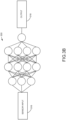
FIG. 3B shows a block diagram of a method for utilizing a neural network according to an exemplary embodiment; -
FIG. 4 shows a flowchart of a method for determining a processing architecture to de-clutter a return signal; - Before explaining various embodiments of the inventive concepts disclosed herein in detail, it is to be understood that the inventive concepts are not limited in their application to the arrangement of the components or steps or methodologies set forth in the following description or illustrated in the drawings. In the following detailed description of embodiments of the instant inventive concepts, numerous specific details are set forth in order to provide a more thorough understanding of the inventive concepts. However, it will be apparent to one of ordinary skill in the art having the benefit of the instant disclosure that the inventive concepts disclosed herein may be practiced without these specific details. In other instances, well-known features may not be described in detail to avoid unnecessarily complicating the instant disclosure. The inventive concepts disclosed herein are capable of other embodiments or of being practiced or carried out in various ways. Also, it is to be understood that the phraseology and terminology employed herein is for the purpose of description and should not be regarded as limiting.
- As used herein a letter following a reference numeral is intended to reference an embodiment of a feature or element that may be similar, but not necessarily identical, to a previously described element or feature bearing the same reference numeral (e.g., 1, 1a, 1b). Such shorthand notations are used for purposes of convenience only, and should not be construed to limit the inventive concepts disclosed herein in any way unless expressly stated to the contrary.
- Further, unless expressly stated to the contrary, "or" refers to an inclusive or and not to an exclusive or. For example, a condition A or B is satisfied by anyone of the following: A is true (or present) and B is false (or not present), A is false (or not present) and B is true (or present), and both A and B are true (or present).
- In addition, use of "a" or "an" are employed to describe elements and components of embodiments of the instant inventive concepts. This is done merely for convenience and to give a general sense of the inventive concepts, and "a" and "an" are intended to include one or at least one and the singular also includes the plural unless it is obvious that it is meant otherwise.
- Also, while various components may be depicted as being connected directly, direct connection is not a requirement. Components may be in data communication with intervening components that are not illustrated or described.
- Finally, as used herein any reference to "one embodiment," or "some embodiments" means that a particular element, feature, structure, or characteristic described in connection with the embodiment is included in at least one embodiment of the inventive concepts disclosed herein. The appearances of the phrase "in at least one embodiment" in the specification does not necessarily refer to the same embodiment. Embodiments of the inventive concepts disclosed may include one or more of the features expressly described or inherently present herein, or any combination or sub-combination of two or more such features.
- Broadly, embodiments of the inventive concepts disclosed herein are directed to an aircraft radar system including an antenna, a processor, and a data storage element. The data storage element includes geolocation data of ground-based structures that are likely to produce ground clutter. Based on the location and orientation of the aircraft, the processor determines where to produce a null or adjust a taper in the antenna beam to exclude the ground clutter. Sensors on the aircraft provide data to geolocate ground clutter inducing targets in real-time. Sensor data is collated, and potentially correlated to stored maps or other databases. A trained machine learning algorithm may receive sensor data and other inputs to identify ground clutter inducing targets, and potentially generate nulls or adjust tapers to exclude such targets. Machine learning algorithms may enable multiple sensors to add multiple data sets to aid with clutter verification; rapid data analytics and adaptation of live data on an air platform; and active nulling which enables adaptive changes in null location and null shapes to efficiently block clutter.
- Referring to
FIG. 1 , a block diagram of a radar system suitable for implementing exemplary embodiments is shown. It is difficult to detect targets that may have ground contamination. Some ground contamination may represent very bright targets (that saturate sensitive radar receive circuitry), even coming through side lobes. Such ground contamination cannot be differentiated from other threats. For low-cost ESAs, the amount of side lobes that we can suppress is smaller than for contemporary, mechanically steered slotted waveguide flat-plate arrays. Current flat-plate arrays may have 2-way side lobes of about 60 dB from the main lobe. ESAs may have 2-way side lobes of 40 dB to 50dB from the main lobe. Suppressing side lobes is paramount, especially to reduce undesired clutter signals embedded within the side lobes that would prevent low level windshear signals from being detected within the main beam. However, when suppressing bright ground clutter, real targets may also be suppressed. - In at least one embodiment, the radar system includes at least one
processor 100,memory 102 connected to theprocessor 100 for embodying non-transitory processor executable code, and anESA antenna 104. Theprocessor 100 is configured to retrieve data from adata storage element 106; the data corresponding to known locations of stationary ground clutter / ground obstacles. Theprocessor 100 determines a relative location of the ground clutter with respect to the aircraft based on the known location of the aircraft and the known locations of the ground clutter. - The
processor 100 determines an electronic configuration for theESA 104 to produce a null toward the determined relative location. Such null excludes the ground clutter and allows theESA 104 to receive return signals from targets that may otherwise by obfuscated by return signals from the ground clutter. The nulls are created by adjusting the phase and amplitude of the ESA's aperture excitation using an adaptive nulling algorithm. It may be appreciated that while specific embodiments described herein are directed to null placement, the methodologies are also applicable to modify sidelobes by adjusting amplitude taper of the signal. - In at least one embodiment, as the as the aircraft moves through space and as the
ESA 104 is steered across the horizon / azimuth, theprocessor 100 recomputes electronic configurations for theESA 104 to maintain the null in direction of the determined location for each subsequent pulse. In at least one embodiment, theprocessor 100 may use a priori information from thedata storage element 106 to apply an adaptive taper. - A priori information from the
data storage element 106 may comprise sets of coordinates and altitudes of known structures. The processor may then receive the location of the aircraft and determine the distance of the aircraft from the coordinates. Alternatively, the a priori information may comprise precomputed nulls to apply at various locations along a flight path. - In at least one embodiment, some or all of the data in the
data storage element 106 may be derived via one ormore sensors 110, including one ormore radars 108 and vision sensors, in data communication with theprocessor 100.Such sensors such sensors data storage element 106 such as maps, data recorded over multiple flights, or other data sets to produce a more complete picture of the surrounding area to determine where nulls are desirable to exclude large, stationary targets. Furthermore, any such data may be received via a datalink connection from external sources. Theprocessor 100 may embody a multi frequency feedback system whereby radar returns and sensor inputs drive beam shaping via sensor fusion. - In at least one embodiment, the
processor 100 may embody a trained AI configured to receive sensor data including data stream from thesensors more radars 108 may be used in conjunction with an object recognition algorithm to locate ground clutter determine a geolocation based on other inputs. Theprocessor 100 may then produce and steer a corresponding null. It may be appreciated that theprocessor 100 may include a general-purpose processor forsensor ESA 104. - In one exemplary embodiment, data from a radio altimeter may be combined with an air data system for heading information and GPS for latitude and longitude to steer a null automatically. Where a stationary, ground clutter (e.g., a bridge) is within radar range, the
processor 100 may place and steer a null in the direction of the ground clutter while the radar is looking further down a runway for windshear, for example. Likewise, during takeoff, that null position may change because the position of the ground clutter with respect to the angle of the radar is changing as the aircraft gets closer to the ground clutter. - While specific descriptions have been directed toward "ground clutter", it may be appreciated that the principles may be applied to any stationary target, whether or not it may be classified as ground clutter, that should be rejected in favor of other targets that might be obscured otherwise.
- In at least one embodiment, the system may embody a multi-mode radar (weather, windshear, detect and avoid, runway imaging, or the like). In such cases, clutter may not necessarily be stationary. For example, it may be desirable to exclude airplanes within view of the radar that may cause some ground clutter or false alerts. The inventive principles described herein are applicable to any application where it would be desirable to exclude targets with a known and predictable relative position with respect to the
ESA 104. - Referring to
FIG. 2 , a 1-way radiation pattern according to an exemplary embodiment is shown. The antenna pattern includes amain lobe 200 and corresponding side lobes. Where ground clutter is within the view or return of the side lobes, such return signals may obscure desirable targets. A null 202 (or taper adjustment) is created and steered using complex weights of the AESA. The 2-way side lobes in the area of interest (around 10 degrees) may be at least 70 dB below themain lobe 200. This will essentially eliminate the return power from any undesired clutter targets. - Referring to
FIGS. 3A-3B , block diagrams of aneural network 300 according an exemplary embodiment of the inventive concepts disclosed herein is shown. Theneural network 300 comprises an input layer, and output layer, and a plurality of internal layers. Each layer comprises a plurality of neurons or nodes. Theneural network 300 receives signals and identifies the locations of non-weather targets such as buildings, trees, mountains, and other ground-based obstacles (or the known locations of mobile obstacles); furthermore, theneural network 300 may be trained to identify patterns of ground clutter. Theneural network 300 may then output nulls at these locations, or adjustments to a taper, to effectively suppress radar echoes from the non-weather targets and reduce ground clutter. - During a training phase, as shown in
FIG. 3A , theneural network 300 receivestraining data 320 includingradar return data 302 tagged with sensor data such asGPS data 304 andaltimeter data 306. Theradar return data 302 may comprise raw data acquisition of the time domain I/Q signal. Such raw data may be represented as a 2-dimensional tensor for a fixed sample time (represented as an image). Thetraining data 320 is associated with anoutput 322 including aradar return signal 314 without clutter. - To train the
neural network 300,training data 320 must include radar return signals 302 with and without clutter and labeled ground truthradar return signal 314. Theoutput data 322 may also includeGPS data 312 andaltimeter data 310. During training, theGPS data altimeter data GPS data altimeter data - The boundary conditions indicate that the system knows what a radar return signal should be at a specific geolocation, as defined by GPS and an altimeter (such as a radio altimeter).
Synchronization 308 ensures that theradar return data 302 at that known GPS location and that known radio altimeter reading is logically constrained to the data labels. For training purposes, it may be insufficient to provide aradar return signal 302 and aradar return signal 314 without clutter for training. Boundary conditions provide additional context to logically constraint the process from providing a false decluttered image. - In at least one embodiment,
radar return signal 302 may be tagged with an I value and a Q value in the time domain, and the corresponding time of the sample. Thetraining data 320 comprises samples for fixed time intervals. Theneural network 300 may be trained to adjust the I/Q values to match expected return value as if the clutter was not present. - During an execution phase, as shown in
FIG. 3B ,input 316 to theneural network 300, including radar return signals, GPS data, and altimeter data, may produce radar return signal outputs with adjustments to the time domain I/Q signal such that theoutput 318 of the neural network is the time domain I/Q with clutter removed, if it's present, for a given GPS geolocation and a given altitude based on the radio altimeter. - While the description herein is directed to a specific implementation of a neural network, it may be appreciated that other machine learning techniques and algorithms are envisioned. For example, a convolution neural network may be trained for image / feature extraction.
- It may be appreciated that while a single
neural network 300 is illustrated, embodiments of the present disclosure may utilize multiple, independent neural networks. - Referring to
FIG. 4 , a flowchart of a method for determining a processing architecture to de-clutter a return signal is shown. The system making the determination may receive aradar return signal 400. Theradar return signal 400 may comprise a time domain I/Q signal. The system determines 402 is if theradar return signal 400 contains clutter; thisdetermination 402 may be algorithmic, selected by a crewmember, or some default setting. If no clutter is present, a system may use 404 theradar return signal 400 without modification. - If the system determines 402 that cutter is (or may be) present, the system may receive
GPS data 406 andaltimeter data 408. Where the system includes a trained neural network, the system may determine 410 if the neural network is trained on data including the boundary constraint of the current geolocation and altitude (e.g., if there is a file in memory corresponding to those boundary constraints). If so, the system may process theradar return signal 400 via the neural network (includingGPS data 406 and altitude data 408) as described herein. The system then proceeds 414 with the processed radar return signal. - If the system determines 410 that the neural network is not trained on data including the boundary constrain of the current geolocation and altitude, or if no trained neural network is present, the system may determine 416 if convention algorithmic processing is desirable. If so (e.g., no a priori data exists for null steering), then the
radar return signal 400 is processed 418 conventionally, and the system proceeds 414 to utilize the processed radar return signal. - If the system determines 416 that conventional processing is not desirable, the system may utilize
null steering 420 to point nulls or adjust tapers at the clutter source in order to minimize the amount of reflected energy from that cluttering objects. Alternatively, or in addition, the system may skew the main beam toward the sky and use a side lobe to pick up the radar return signal and minimize the intensity coming from the clutter source. - Accurately detecting threats is key to developing an ESA radar for autonomous operation. Mitigating false windshear alerts due to ground clutter is essential for achieving full MOPS compliance. Adaptively adjusting the taper on receive will provide a path towards full MOPS compliance by minimizing side lobe clutter while preserving SNR. Our competitors are also currently pursuing an ESA solution.
- Embodiments of the present disclosure enable an enhanced weather radar system for applications such as aviation, meteorology, and military surveillance. They provide an efficient and effective solution for reducing ground clutter and improving the detection of weather phenomena. In addition to weather detection, dynamic antenna pattern nulling can also be used for "down-looking" where the radar is tasked with searching and tracking several airborne targets within a high ground clutter environment. In a complex search and track environment, embodiments can steer a null in the direction of clutter (ground or weather) while preserving the integrity of the target detection, as reference against absolute "earth" coordinates.
- It is believed that the inventive concepts disclosed herein and many of their attendant advantages will be understood by the foregoing description of embodiments of the inventive concepts, and it will be apparent that various changes may be made in the form, construction, and arrangement of the components thereof without departing from the broad scope of the inventive concepts disclosed herein or without sacrificing all of their material advantages; and individual features from various embodiments may be combined to arrive at other embodiments. The forms herein before described being merely explanatory embodiments thereof, it is the intention of the following claims to encompass and include such changes. Furthermore, any of the features disclosed in relation to any of the individual embodiments may be incorporated into any other embodiment.
Claims (15)
- A computer apparatus comprising:
an electronically scanned array "ESA" antenna;a data storage element (106); andat least one processor (100) in data communication with the ESA antenna, the
data storage element (106), and a memory storing processor (100) executable code for configuring the at least one processor (100) to:determine a relative location of a ground clutter source with respect to the ESA antenna;determine an electronic configuration to produce a null in a radiation pattern of the ESA corresponding to the relative location of the ground clutter source; andcontinuously steer the null to maintain a relative orientation of the null toward the ground clutter source. - The computer apparatus of Claim 1, wherein the at least one processor (100) is configured to retrieve a predetermined geolocation of the ground clutter source from the data storage element (106).
- The computer apparatus of Claim 1 or 2, further comprising a plurality of sensors, wherein the at least one processor (100) is further configured to:receive a plurality of sensor streams from the plurality of sensors;collate the sensor streams based on time stamps and an aircraft location and altitude; andidentify one or more ground clutter sources based on the sensor streams.
- The computer apparatus of Claim 3, wherein:the at least one processor (100) is configured as a trained neural network; andthe trained neural network is configured to:receive at least the sensor streams;determine a current geolocation;determine that the neural network is trained for the current geolocation; anddetermine an I/Q adjustment to a radar return signal.
- The computer apparatus of Claim 3, wherein the plurality of sensors includes one or more of GPS/GNSS receivers, Precision Navigation Timing "PNT", weather radar relative navigation, radar landing altimeter, Electro-optic runway landing imagers, TACAN, LORAN and glide slope/localizer landing systems.
- The computer apparatus of any preceding Claim, wherein the null is at least 70 dB below a main lobe in the radiation pattern, or wherein the at least one processor (100) comprises a processor (100) configured to determine the relative location and a filed programmable gate array configured to produce the electronic configuration.
- A method comprising:determining a relative location of a ground clutter source with respect to an electronically scanned array "ESA" antenna;determining an electronic configuration to adjust an amplitude taper or non-uniform phase distribution along an aperture of the ESA antenna to create a radiation pattern of the ESA to manipulate side lobe levels at a location corresponding to the relative location of the ground clutter source; andcontinuously adjusting the amplitude taper to maintain the manipulated side lobe levels toward the ground clutter source.
- The method of Claim 7, further comprising retrieving a predetermined
geolocation of the ground clutter source from a data storage element (106), or further comprising:receiving a plurality of sensor streams from a plurality of sensors;collating the sensor streams based on time stamps and an aircraft location and altitude; andidentifying one or more ground clutter sources based on the sensor streams. - The method of Claim 8, wherein:
a trained neural network is configured to:receive at least the sensor streams;determine a current geolocation;determine that the neural network is trained for the current geolocation; anddetermine an I/Q adjustment to a radar return signal, or wherein the plurality of sensors includes one or more of GPS/GNSS receivers, Precision Navigation Timing "PNT", weather radar relative navigation, radar landing altimeter, Electro-optic runway landing imagers, TACAN, LORAN and glide slope/localizer landing systems. - The method of Claim 7, wherein the side lobe level is at least 70 dB below a main lobe in the radiation pattern at the location corresponding to the relative location of the ground clutter source.
- A multi-mode radar system comprising:an electronically scanned array "ESA" antenna;a data storage element (106); andat least one processor (100) in data communication with the ESA antenna, the data storage element (106), and a memory storing processor (100) executable code for configuring the at least one processor (100) to:determine a relative location of a ground clutter source with respect to the ESA antenna;determine an electronic configuration to produce a null in a radiation pattern of the ESA corresponding to the relative location of the ground clutter source; andcontinuously steer the null to maintain a relative orientation of the null toward the ground clutter source.
- The multi-mode radar system of Claim 11, wherein the at least one processor (100) is configured to retrieve a predetermined geolocation of the ground clutter source from the data storage element (106).
- The multi-mode radar system of Claim 11 or 12, further comprising a plurality of sensors, wherein the at least one processor (100) is further configured to:receive a plurality of sensor streams from the plurality of sensors;collate the sensor streams based on time stamps and an aircraft location and altitude; andidentify one or more ground clutter sources based on the sensor streams.
- The multi-mode radar system of Claim 13, wherein:the at least one processor (100) is configured as a trained neural network; andthe trained neural network is configured to:receive at least the sensor streams;determine a current geolocation;determine that the neural network is trained for the current geolocation; anddetermine an I/Q adjustment to a radar return signal, or wherein the plurality of sensors includes one or more of GPS/GNSS receivers, Precision Navigation Timing "PNT", multi-mode radar relative navigation, radar landing altimeter, Electro-optic runway landing imagers, TACAN, LORAN and glide slope/localizer landing systems.
- The multi-mode radar system of Claim 11, wherein the null is at least 70 dB below a main lobe in the radiation pattern, or wherein the at least one processor (100) comprises a processor (100) configured to determine the relative location and a filed programmable gate array configured to produce the electronic configuration.
Applications Claiming Priority (1)
| Application Number | Priority Date | Filing Date | Title |
|---|---|---|---|
| US18/239,297 US20250076482A1 (en) | 2023-08-29 | 2023-08-29 | Sensor fusion-based gcs for aesa radar via adaptive pattern null forming |
Publications (1)
| Publication Number | Publication Date |
|---|---|
| EP4517365A1 true EP4517365A1 (en) | 2025-03-05 |
Family
ID=92208809
Family Applications (1)
| Application Number | Title | Priority Date | Filing Date |
|---|---|---|---|
| EP24192330.9A Pending EP4517365A1 (en) | 2023-08-29 | 2024-08-01 | Sensor fusion-based gcs for aesa radar via adaptive pattern null forming |
Country Status (2)
| Country | Link |
|---|---|
| US (1) | US20250076482A1 (en) |
| EP (1) | EP4517365A1 (en) |
Families Citing this family (1)
| Publication number | Priority date | Publication date | Assignee | Title |
|---|---|---|---|---|
| US20250251491A1 (en) * | 2024-02-05 | 2025-08-07 | Rockwell Collins, Inc. | Antenna offset principal plane sidelobes for enhanced ground clutter suppression |
Citations (3)
| Publication number | Priority date | Publication date | Assignee | Title |
|---|---|---|---|---|
| US8203480B1 (en) * | 2003-07-31 | 2012-06-19 | Rockwell Collins, Inc. | Predictive and adaptive weather radar detection system and method |
| US11181634B1 (en) * | 2018-09-28 | 2021-11-23 | Rockwell Collins, Inc. | Systems and methods of intelligent weather sensing using deep learning convolutional neural networks |
| US20220082687A1 (en) * | 2020-09-17 | 2022-03-17 | Rockwell Collins, Inc. | Agile Antenna Taper Based On Weather Radar Feedback |
Family Cites Families (5)
| Publication number | Priority date | Publication date | Assignee | Title |
|---|---|---|---|---|
| US5173706A (en) * | 1991-04-16 | 1992-12-22 | General Electric Company | Radar processor with range sidelobe reduction following doppler filtering |
| US6633253B2 (en) * | 2001-04-02 | 2003-10-14 | Thomas J. Cataldo | Dual synthetic aperture radar system |
| US9019145B1 (en) * | 2011-07-14 | 2015-04-28 | Rockwell Collins, Inc. | Ground clutter rejection for weather radar |
| US10775498B2 (en) * | 2017-03-13 | 2020-09-15 | Honeywell International Inc. | Methods for a multi-function electronically steered weather radar |
| US10754020B2 (en) * | 2017-08-30 | 2020-08-25 | Honeywell International Inc. | Mechanically assisted phased array for extended scan limits |
-
2023
- 2023-08-29 US US18/239,297 patent/US20250076482A1/en active Pending
-
2024
- 2024-08-01 EP EP24192330.9A patent/EP4517365A1/en active Pending
Patent Citations (3)
| Publication number | Priority date | Publication date | Assignee | Title |
|---|---|---|---|---|
| US8203480B1 (en) * | 2003-07-31 | 2012-06-19 | Rockwell Collins, Inc. | Predictive and adaptive weather radar detection system and method |
| US11181634B1 (en) * | 2018-09-28 | 2021-11-23 | Rockwell Collins, Inc. | Systems and methods of intelligent weather sensing using deep learning convolutional neural networks |
| US20220082687A1 (en) * | 2020-09-17 | 2022-03-17 | Rockwell Collins, Inc. | Agile Antenna Taper Based On Weather Radar Feedback |
Also Published As
| Publication number | Publication date |
|---|---|
| US20250076482A1 (en) | 2025-03-06 |
Similar Documents
| Publication | Publication Date | Title |
|---|---|---|
| US12189020B2 (en) | Radar based system and method for detection of an object and generation of plots holding radial velocity data, and system for detection and classification of unmanned aerial vehicles, UAVs | |
| US12475806B2 (en) | Flight management system departure and arrival performance display based on weather data uplink | |
| US7808422B1 (en) | Predictive and adaptive weather radar detection system and method | |
| US8203480B1 (en) | Predictive and adaptive weather radar detection system and method | |
| US5654890A (en) | High resolution autonomous precision approach and landing system | |
| Musa et al. | A review of copter drone detection using radar systems | |
| US20190204414A1 (en) | Methods and systems for calibrating and/or testing radars or antennas | |
| KR102593466B1 (en) | Multi-angle synthetic aperture radar image processing method and apparatus therefor | |
| KR102260239B1 (en) | Terrain following flight method | |
| US20250076482A1 (en) | Sensor fusion-based gcs for aesa radar via adaptive pattern null forming | |
| KR101750507B1 (en) | Synthetic aperture radar seeker and target identification method thereof | |
| Fasano et al. | Sky region obstacle detection and tracking for vision-based UAS sense and avoid | |
| KR102260240B1 (en) | Terrain following flight method | |
| Maas et al. | A portable primary radar for general aviation | |
| JP7364153B2 (en) | Coordinated airspace exploration | |
| US9753123B2 (en) | System and method to provide a dynamic situational awareness of attack radar threats | |
| Wilson | Ground-based sense and avoid support for unmanned aircraft systems | |
| US20250012891A1 (en) | Systems and methods for forward-scatter sensing | |
| Martinez et al. | Detect and avoid considerations for safe suas operations in urban environments | |
| Pirkl et al. | HiVision millimeter-wave radar for enhanced vision systems in civil and military transport aircraft | |
| Veneruso et al. | Radar-visual navigation for all-weather approach and landing to vertiports | |
| Moses | Radar based collision avoidance for unmanned aircraft systems | |
| Veneruso et al. | Assessing Radar-Aided Navigation for UAM Approach and Landing Through High-Fidelity Simulations and Flight Testing | |
| Roa et al. | Radar and UAV: georeferencing and airspace surveillance system | |
| RU2799866C1 (en) | Radar method for detecting unmanned aerial vehicles |
Legal Events
| Date | Code | Title | Description |
|---|---|---|---|
| PUAI | Public reference made under article 153(3) epc to a published international application that has entered the european phase |
Free format text: ORIGINAL CODE: 0009012 |
|
| STAA | Information on the status of an ep patent application or granted ep patent |
Free format text: STATUS: THE APPLICATION HAS BEEN PUBLISHED |
|
| AK | Designated contracting states |
Kind code of ref document: A1 Designated state(s): AL AT BE BG CH CY CZ DE DK EE ES FI FR GB GR HR HU IE IS IT LI LT LU LV MC ME MK MT NL NO PL PT RO RS SE SI SK SM TR |
|
| STAA | Information on the status of an ep patent application or granted ep patent |
Free format text: STATUS: REQUEST FOR EXAMINATION WAS MADE |
|
| 17P | Request for examination filed |
Effective date: 20250903 |
|
| RIC1 | Information provided on ipc code assigned before grant |
Ipc: G01S 7/28 20060101AFI20251121BHEP Ipc: G01S 7/41 20060101ALI20251121BHEP Ipc: G01S 13/95 20060101ALI20251121BHEP Ipc: G06N 3/08 20230101ALI20251121BHEP Ipc: G01S 13/02 20060101ALN20251121BHEP |
|
| GRAP | Despatch of communication of intention to grant a patent |
Free format text: ORIGINAL CODE: EPIDOSNIGR1 |
|
| STAA | Information on the status of an ep patent application or granted ep patent |
Free format text: STATUS: GRANT OF PATENT IS INTENDED |
|
| RIC1 | Information provided on ipc code assigned before grant |
Ipc: G01S 7/28 20060101AFI20251210BHEP Ipc: G01S 7/41 20060101ALI20251210BHEP Ipc: G01S 13/95 20060101ALI20251210BHEP Ipc: G06N 3/08 20230101ALI20251210BHEP Ipc: G01S 13/02 20060101ALN20251210BHEP |
|
| RIC1 | Information provided on ipc code assigned before grant |
Ipc: G01S 7/28 20060101AFI20251217BHEP Ipc: G01S 7/41 20060101ALI20251217BHEP Ipc: G01S 13/95 20060101ALI20251217BHEP Ipc: G06N 3/08 20230101ALI20251217BHEP Ipc: G01S 13/02 20060101ALN20251217BHEP |
|
| INTG | Intention to grant announced |
Effective date: 20260105 |
|
| GRAJ | Information related to disapproval of communication of intention to grant by the applicant or resumption of examination proceedings by the epo deleted |
Free format text: ORIGINAL CODE: EPIDOSDIGR1 |
|
| STAA | Information on the status of an ep patent application or granted ep patent |
Free format text: STATUS: REQUEST FOR EXAMINATION WAS MADE |