EP4517346A1 - Fault identification method and system based on full-time-domain abrupt change information, electronic device, and computer-readable storage medium - Google Patents
Fault identification method and system based on full-time-domain abrupt change information, electronic device, and computer-readable storage medium Download PDFInfo
- Publication number
- EP4517346A1 EP4517346A1 EP22947607.2A EP22947607A EP4517346A1 EP 4517346 A1 EP4517346 A1 EP 4517346A1 EP 22947607 A EP22947607 A EP 22947607A EP 4517346 A1 EP4517346 A1 EP 4517346A1
- Authority
- EP
- European Patent Office
- Prior art keywords
- fault
- phase
- denotes
- current
- flexible
- Prior art date
- Legal status (The legal status is an assumption and is not a legal conclusion. Google has not performed a legal analysis and makes no representation as to the accuracy of the status listed.)
- Pending
Links
Images



Classifications
-
- G—PHYSICS
- G01—MEASURING; TESTING
- G01R—MEASURING ELECTRIC VARIABLES; MEASURING MAGNETIC VARIABLES
- G01R19/00—Arrangements for measuring currents or voltages or for indicating presence or sign thereof
- G01R19/25—Arrangements for measuring currents or voltages or for indicating presence or sign thereof using digital measurement techniques
- G01R19/2513—Arrangements for monitoring electric power systems, e.g. power lines or loads; Logging
-
- G—PHYSICS
- G01—MEASURING; TESTING
- G01R—MEASURING ELECTRIC VARIABLES; MEASURING MAGNETIC VARIABLES
- G01R31/00—Arrangements for testing electric properties; Arrangements for locating electric faults; Arrangements for electrical testing characterised by what is being tested not provided for elsewhere
- G01R31/08—Locating faults in cables, transmission lines, or networks
- G01R31/081—Locating faults in cables, transmission lines, or networks according to type of conductors
- G01R31/085—Locating faults in cables, transmission lines, or networks according to type of conductors in power transmission or distribution lines, e.g. overhead
-
- G—PHYSICS
- G01—MEASURING; TESTING
- G01R—MEASURING ELECTRIC VARIABLES; MEASURING MAGNETIC VARIABLES
- G01R31/00—Arrangements for testing electric properties; Arrangements for locating electric faults; Arrangements for electrical testing characterised by what is being tested not provided for elsewhere
- G01R31/08—Locating faults in cables, transmission lines, or networks
- G01R31/088—Aspects of digital computing
-
- H—ELECTRICITY
- H02—GENERATION; CONVERSION OR DISTRIBUTION OF ELECTRIC POWER
- H02H—EMERGENCY PROTECTIVE CIRCUIT ARRANGEMENTS
- H02H1/00—Details of emergency protective circuit arrangements
- H02H1/0092—Details of emergency protective circuit arrangements concerning the data processing means, e.g. expert systems, neural networks
-
- H—ELECTRICITY
- H02—GENERATION; CONVERSION OR DISTRIBUTION OF ELECTRIC POWER
- H02H—EMERGENCY PROTECTIVE CIRCUIT ARRANGEMENTS
- H02H3/00—Emergency protective circuit arrangements for automatic disconnection directly responsive to an undesired change from normal electric working condition with or without subsequent reconnection ; integrated protection
- H02H3/44—Emergency protective circuit arrangements for automatic disconnection directly responsive to an undesired change from normal electric working condition with or without subsequent reconnection ; integrated protection responsive to the rate of change of electrical quantities
-
- H—ELECTRICITY
- H02—GENERATION; CONVERSION OR DISTRIBUTION OF ELECTRIC POWER
- H02H—EMERGENCY PROTECTIVE CIRCUIT ARRANGEMENTS
- H02H7/00—Emergency protective circuit arrangements specially adapted for specific types of electric machines or apparatus or for sectionalised protection of cable or line systems, and effecting automatic switching in the event of an undesired change from normal working conditions
- H02H7/26—Sectionalised protection of cable or line systems, e.g. for disconnecting a section on which a short-circuit, earth fault, or arc discharge has occured
- H02H7/261—Sectionalised protection of cable or line systems, e.g. for disconnecting a section on which a short-circuit, earth fault, or arc discharge has occured involving signal transmission between at least two stations
- H02H7/263—Sectionalised protection of cable or line systems, e.g. for disconnecting a section on which a short-circuit, earth fault, or arc discharge has occured involving signal transmission between at least two stations involving transmissions of measured values
-
- Y—GENERAL TAGGING OF NEW TECHNOLOGICAL DEVELOPMENTS; GENERAL TAGGING OF CROSS-SECTIONAL TECHNOLOGIES SPANNING OVER SEVERAL SECTIONS OF THE IPC; TECHNICAL SUBJECTS COVERED BY FORMER USPC CROSS-REFERENCE ART COLLECTIONS [XRACs] AND DIGESTS
- Y04—INFORMATION OR COMMUNICATION TECHNOLOGIES HAVING AN IMPACT ON OTHER TECHNOLOGY AREAS
- Y04S—SYSTEMS INTEGRATING TECHNOLOGIES RELATED TO POWER NETWORK OPERATION, COMMUNICATION OR INFORMATION TECHNOLOGIES FOR IMPROVING THE ELECTRICAL POWER GENERATION, TRANSMISSION, DISTRIBUTION, MANAGEMENT OR USAGE, i.e. SMART GRIDS
- Y04S10/00—Systems supporting electrical power generation, transmission or distribution
- Y04S10/50—Systems or methods supporting the power network operation or management, involving a certain degree of interaction with the load-side end user applications
- Y04S10/52—Outage or fault management, e.g. fault detection or location
Definitions
- the present disclosure relates to the field of power system protection technology, and relates to, but is not limited to, a fault identification method and a system based on full-time-domain abrupt change information, an electronic device, and a computer-readable storage medium.
- full-time-domain information protection represents the difference between the current transient waveforms of the new energy station and the current transient waveforms of the power grid by cosine similarity, Spearman grade correlation coefficient, Pearson correlation coefficient, or the like.
- cosine similarity Spearman grade correlation coefficient
- Pearson correlation coefficient Pearson correlation coefficient
- the conventional protection method using power frequency quantity information needs to extract the power frequency quantity information from sample values of the current and voltage after the fault, so as to form a protection criterion.
- line fault information adopted by such method is mainly the power frequency quantity, it is easy to be affected by characteristics of the new energy station, such as the limited amplitude of the short-circuit current, the controlled phase angle, the frequency deviation, or the like, which leads to the decrease of the protection performance. Therefore, a new fault identification method is urgently needed when the high-voltage Alternating Current (AC) line fails.
- AC Alternating Current
- the present disclosure proposes a fault identification method and a system based on full-time-domain abrupt change information, so as to solve the problem of how to achieve high-voltage AC line fault identification efficiently and improve the protection capacity of the power system.
- a fault identification method based on full-time-domain abrupt change information includes the following operations.
- a respective multi-order matrix is constructed according to the fault current of the phase on the wind farm side and the flexible DC side, and a respective abrupt change characteristic value corresponding to the fault current of the phase on the wind farm side and the flexible DC side is calculated according to the multi-order matrix.
- a respective fault type is determined according to a preset criterion and the abrupt change characteristic value corresponding to the fault current of the phase on the wind farm side and the flexible DC side.
- i mmc ⁇ E f cos ⁇ t + ⁇ ⁇ Z eq + m E f Z eq + i w ⁇ cos ⁇ ⁇ t + ⁇ ⁇ ⁇
- i w ⁇ denotes a fault current of a phase ⁇ on the wind farm side.
- i d ⁇ denotes a preset current reference value of a d-axis
- i q ⁇ denotes a preset current reference value of a q-axis.
- ⁇ PLL denotes a fundamental angular frequency.
- ⁇ ⁇ denotes an initial phase angle.
- ⁇ d denotes a damped natural frequency
- ⁇ d ⁇ n (1- ⁇ 2 ) 1/2
- ⁇ n denotes a natural oscillation angular frequency when a damping of the second-order system is zero
- ⁇ n ( k ii / L ) 1/2
- ⁇ denotes a damping angle of a system
- ⁇ arctan((1- ⁇ 2 ) 1/2 / ⁇ ).
- P denotes a single-phase output active power.
- u d denotes a voltage of the d-axis.
- i d 0 denotes an initial current of the d-axis.
- t denotes fault time.
- k ip denotes a ratio of a current control loop.
- k ii denotes an integral time constant.
- L denotes a bridge arm inductance.
- i mmc ⁇ denotes a fault current of the phase ⁇ on the flexible DC side.
- E f denotes an electric potential within a converter.
- Z eq denotes an equivalent impedance.
- ⁇ denotes an angular frequency of a positive sequence current
- ⁇ - denotes an angular frequency of a negative sequence current.
- m denotes a ratio coefficient related to a short-circuit type.
- ⁇ ⁇ - denotes an initial phase angle of the negative sequence current.
- the operation that the respective multi-order matrix is constructed according to the fault current of the phase on the wind farm side and the flexible DC side, and the respective abrupt change characteristic value corresponding to the fault current of the phase on the wind farm side and the flexible DC side is calculated according to the multi-order matrix includes the following operations.
- the following operations are performed for the fault current of the phase on the wind farm side and the flexible DC side to acquire the abrupt change characteristic value corresponding to the fault current of the phase on the wind farm side and the flexible DC side.
- the multi-order matrix I T is transformed into expressions of row vectors and column vectors.
- G denotes the abrupt change characteristic value corresponding to the fault current of the phase.
- Gx denotes the horizontal gradient matrix
- Gy denotes the vertical gradient matrix.
- Gx ( i , j ) denotes an element in an i-th row and a j-th column of the horizontal gradient matrix.
- Gy ( i , j ) denotes an element in an i-th row and a j-th column of the vertical gradient matrix.
- the operation that the respective fault type is determined according to the preset criterion and the abrupt change characteristic value corresponding to the fault current of the phase on the wind farm side and the flexible DC side includes the following operations.
- a fault type of the phase is determined as an in-region fault.
- the fault type of the phase is determined as an out-of-region fault.
- G 1 denotes the abrupt change characteristic value corresponding to the fault current of the phase on the wind farm side
- G 2 denotes the abrupt change characteristic value corresponding to the fault current of the phase on the flexible DC side
- G set denotes a preset setting value.
- a phase with the fault type of an in-region fault is determined as a fault phase, and an exit is protected according to the number of fault phases.
- a relay protection apparatus is controlled to send a fault phase trip instruction to control the fault phase to trip and control a non-fault phase to operate normally. If the number of the fault phases is greater than the preset number, the relay protection apparatus is controlled to send a three-phase trip instruction to control all of three phases to trip.
- the present disclosure provides a fault identification system based on full-time-domain abrupt change information.
- the system includes a fault current acquisition unit, an abrupt change characteristic value calculation unit and a fault type determination unit.
- the fault current acquisition unit is configured to collect, when a high-voltage AC line fails, current signals on a wind farm side and a flexible DC side, to acquire a respective fault current of each phase on the wind farm side and the flexible DC side.
- the abrupt change characteristic value calculation unit is configured to: for each fault current of a respective phase on the wind farm side and the flexible DC side, construct a respective multi-order matrix according to the fault current of the phase on the wind farm side and the flexible DC side, and calculate, according to the multi-order matrix, a respective abrupt change characteristic value corresponding to the fault current of the phase on the wind farm side and the flexible DC side.
- the fault type determination unit is configured to determine a respective fault type according to a preset criterion and the abrupt change characteristic value corresponding to the fault current of the phase on the wind farm side and the flexible DC side.
- i mmc ⁇ E f cos ⁇ t + ⁇ ⁇ Z eq + m E f Z eq + i w ⁇ cos ⁇ ⁇ t + ⁇ ⁇ ⁇
- i w ⁇ denotes a fault current of a phase ⁇ on the wind farm side.
- i d ⁇ denotes a preset current reference value of a d-axis
- i q ⁇ denotes a preset current reference value of a q-axis.
- ⁇ PLL denotes a fundamental angular frequency.
- ⁇ ⁇ denotes an initial phase angle.
- ⁇ d denotes a damped natural frequency
- ⁇ d ⁇ n (1- ⁇ 2 ) 1/2
- ⁇ n denotes a natural oscillation angular frequency when a damping of the second-order system is zero
- ⁇ n ( k ii / L ) 1/2
- ⁇ denotes a damping angle of a system
- ⁇ arctan((1- ⁇ 2 ) 1/2 / ⁇ ).
- P denotes a single-phase output active power.
- u d denotes a voltage of the d-axis.
- i d 0 denotes an initial current of the d-axis.
- t denotes fault time.
- k ip denotes a ratio of a current control loop.
- k ii denotes an integral time constant.
- L denotes a bridge arm inductance.
- i mmc ⁇ denotes a fault current of the phase ⁇ on the flexible DC side.
- E f denotes an electric potential within a converter.
- Z eq denotes an equivalent impedance.
- ⁇ denotes an angular frequency of a positive sequence current
- ⁇ - denotes an angular frequency of a negative sequence current.
- m denotes a ratio coefficient related to a short-circuit type.
- ⁇ ⁇ - denotes an initial phase angle of the negative sequence current.
- the abrupt change characteristic value calculation unit is further configured to perform the following operations for the fault current of the phase on the wind farm side and the flexible DC side to acquire the abrupt change characteristic value corresponding to the fault current of the phase on the wind farm side and the flexible DC side.
- the multi-order matrix I T is transformed into expressions of row vectors and column vectors.
- G denotes the abrupt change characteristic value corresponding to the fault current of the phase.
- Gx denotes the horizontal gradient matrix
- Gy denotes the vertical gradient matrix.
- Gx ( i , j ) denotes an element in an i-th row and a j-th column of the horizontal gradient matrix.
- Gy ( i , j ) denotes an element in an i-th row and a j-th column of the vertical gradient matrix.
- the fault type determination unit is further configured to: for any phase, if fault currents on the wind farm side and the flexible DC side corresponding to the phase meet the preset criterion, determine a fault type of the phase as an in-region fault;
- the fault type of the phase as an out-of-region fault.
- G 1 denotes the abrupt change characteristic value corresponding to the fault current of the phase on the wind farm side
- G 2 denotes the abrupt change characteristic value corresponding to the fault current of the phase on the flexible DC side
- G set denotes a preset setting value.
- the fault type determination unit is further configured to: determine a phase with the fault type of the in-region fault as a fault phase, and protect an exit according to the number of the fault phases;
- control a relay protection apparatus to send a fault phase trip instruction to control the fault phase to trip and control a non-fault phase to operate normally; and if the number of the fault phases is greater than the preset number, control the relay protection apparatus to send a three-phase trip instruction to control all of three phases to trip.
- the present disclosure provides an electronic device including a memory, a processor, and a computer program stored in the memory and executable on the processor.
- the processor when executing the computer program, implements the operations of the above method.
- the present disclosure provides a computer-readable storage medium having stored thereon a computer program.
- the computer program when executed by a processor, implements the operations of the above method.
- the present disclosure provides a fault identification method based on full-time-domain abrupt change information, a system, an electronic device, and a computer-readable storage medium.
- the high-voltage AC line fails, the current signals on the wind farm side and the flexible DC side are collected, and a respective fault current of each phase on the wind farm side and the flexible DC side are acquired.
- a respective multi-order matrix is constructed according to the fault current of the phase on the wind farm side and the flexible DC side, and according to the multi-order matrixes, a respective abrupt change characteristic value corresponding to the fault current of the phase on the wind farm side and the flexible DC side is calculated.
- a respective fault type is determined according to a preset criterion and the abrupt change characteristic value corresponding to the fault current of the phase on the wind farm side and the flexible DC side.
- the current signals of the phases on both sides of the line are used to construct multi-order matrixes respectively.
- the characteristic that the multi-order matrix may quickly amplify the proportion of abrupt change signals and the advantage that the matrix gradient may accurately represent the degree of the abrupt change of data are comprehensively used to construct the protection criterion, so as to achieve the high-speed and reliable fault identification, thereby solving the problem of the risk of sensitivity decrease of conventional protection and the risk of incorrect operation in the new power system.
- the present disclosure may adapt to a scenario of access and delivery of multiple types of new energy power supplies without depending on the power frequency quantity, and have a capacity to withstand the transition resistance and noise and a rapid responsiveness, which has an important engineering significance for the high proportion consumption of the future new energy and the safe operation of the power grid, and provides the premise and guarantee for further development of the new energy power electronic system with a high proportion in the future.
- the short-circuit current presents characteristics such as limited amplitude, non-power frequency, controlled phase angle, or the like, which are completely different from those of a synchronous generator.
- FIG. 1 is a flowchart of a fault identification method 100 based on full-time-domain abrupt change information according to an implementation of the present disclosure.
- the current signals of the phases on both sides of the line are used to construct multi-order matrixes respectively.
- the characteristic that the multi-order matrix may quickly amplify the proportion of abrupt change signals and the advantage that the matrix gradient may accurately represent the degree of the abrupt change of data are comprehensively used to construct the protection criterion, so as to achieve the high-speed and reliable fault identification, thereby solving the problem of the risk of sensitivity decrease of conventional protection and the risk of incorrect operation in the new power system.
- the present disclosure may adapt to a scenario of access and delivery of multiple types of new energy power supplies without depending on the power frequency quantity, and have a capacity to withstand the transition resistance and noise and a rapid responsiveness, which has an important engineering significance for the high proportion consumption of the future new energy and the safe operation of the power grid, and provides the premise and guarantee for further development of the new energy power electronic system with a high proportion in the future.
- the fault identification method 100 based on the full-time-domain abrupt change information provided by the implementation of the present disclosure may be achieved by the following operations.
- the fault current of the phase on the wind farm side may be represented by the following formula 1.
- i w ⁇ 2 P 3 u d cos ⁇ PLL t + ⁇ ⁇ ⁇ i q ⁇ sin ⁇ PLL t + ⁇ ⁇ + i d 0 ⁇ 2 P 3 u d 1 1 ⁇ ⁇ 2 e ⁇ ⁇ n t ⁇ sin ⁇ d t + ⁇ ⁇ cos ⁇ PLL t + ⁇ ⁇ + i q ⁇ 2 Lk ii 4 k ii L ⁇ k ip 2 e ⁇ k ip / 2 L t ⁇ sin 4 k ii L ⁇ k ip 2 2 L t + ⁇ ⁇ sin ⁇ PLL t + ⁇ ⁇ ⁇
- the fault current of the phase on the flexible DC side may be represented by the following formula 2.
- i mmc ⁇ E f cos ⁇ t + ⁇ ⁇ Z eq + m E f Z eq + i w ⁇ cos ⁇ ⁇ t + Q ⁇ ⁇
- i w ⁇ denotes a fault current of a phase ⁇ on the wind farm side.
- i d ⁇ denotes a preset current reference value of a d-axis
- i q ⁇ denotes a preset current reference value of a q-axis.
- ⁇ PLL denotes a fundamental angular frequency.
- ⁇ ⁇ denotes an initial phase angle.
- ⁇ d denotes a damped natural frequency
- ⁇ d ⁇ n (1- ⁇ 2 ) 1/2
- ⁇ n denotes a natural oscillation angular frequency when a damping of the second-order system is zero
- ⁇ n ( k ii / L ) 1/2
- ⁇ denotes a damping angle of a system
- ⁇ arctan((1- ⁇ 2 ) 1/2 / ⁇ ).
- P denotes a single-phase output active power.
- u d denotes a voltage of the d-axis.
- i d 0 denotes an initial current of the d-axis.
- t denotes fault time.
- k ip denotes a ratio of a current control loop.
- k ii denotes an integral time constant.
- L denotes a bridge arm inductance.
- i mmc ⁇ denotes a fault current of the phase ⁇ on the flexible DC side.
- E f denotes an electric potential within a converter.
- Z eq denotes an equivalent impedance.
- ⁇ denotes an angular frequency of a positive sequence current
- ⁇ - denotes an angular frequency of a negative sequence current.
- m denotes a ratio coefficient related to a short-circuit type.
- ⁇ ⁇ - denotes an initial phase angle of the negative sequence current.
- in-region and out-of-region faults of the AC line on which the new energy is sent through the grid-connection on the flexible DC side are analyzed to clarify characteristics of in-region and out-of-region fault currents.
- single-phase current signals collected within time windows on both sides are constructed into a multi-order matrix.
- the wind power converter is the only power outlet of the permanent magnet fan. Due to a limited overcurrent capacity, in order to protect the power electronic components of the converter, the control system mainly uses amplitude limit control and negative sequence current control.
- the short-circuit current of each phase on the wind farm side may be represented by the above formula 1.
- the short-circuit current of the wind farm is controlled by the reference values of the currents of the d-axis and q-axis of the control system of the converter, and the wind farm is equivalent to a controlled current source. Due to a limited capacity of the converter to withstand overcurrent, the short-circuit current is generally 1.5-2 times the maximum rated current. Therefore, the wind farm has a characteristic of limited amplitude of the fault current.
- the converter at the sending end on the flexible DC side is coupled to a controlled current source, it is generally controlled by AC voltage-frequency and is equivalent to a controlled voltage source.
- the fault current before the converter at the sending end on the flexible DC side is blocked may be represented by the above formula 2.
- the short-circuit current provided by the flexible DC converter has a positive sequence component and a negative sequence component simultaneously.
- the converter is equivalent to a controlled voltage source, and the amplitude of the short-circuit current depends on the equivalent internal potential and equivalent impedance of the flexible DC converter.
- the fault current of the converter has a limited amplitude and lacks a continuous and stable power frequency component, which seriously affects the correct fault identification of the conventional current differential protection principle. Sensitivity will decrease during the calculation process of the protection apparatus, and there is a risk of incorrect operation.
- different converter control reflects different control response characteristics, which thus determines that the abrupt change characteristics of the short-circuit current after the fault are different and are all different from those of a conventional synchronous machine.
- a respective multi-order matrix is constructed according to the fault current of the phase on the wind farm side and the flexible DC side, and a respective abrupt change characteristic value corresponding to the fault current of the phase on the wind farm side and the flexible DC side is calculated according to the multi-order matrix.
- the operation that the respective multi-order matrix is constructed according to the fault current of the phase on the wind farm side and the flexible DC side, and the respective abrupt change characteristic value corresponding to the fault current of the phase on the wind farm side and the flexible DC side is calculated according to the multi-order matrix includes the following operations.
- the following operations are performed for the fault current of the phase on the wind farm side and the flexible DC side to acquire the abrupt change characteristic value corresponding to the fault current of the phase on the wind farm side and the flexible DC side.
- the multi-order matrix may be represented by the following formula 3.
- I T i 1 i 2 i 3 ... i N i 2 i 1 i 2 ... i N ⁇ 1 i 3 i 2 i 1 ... i N ⁇ 2 : : : : : : : : : : : : : : : : : i N i N ⁇ 1 i N ⁇ 2 ... i 1 N ⁇ N
- the multi-order matrix I T is transformed into expressions of row vectors and column vectors.
- a horizontal gradient matrix corresponding to the multi-order matrix with the expression of the column vectors is calculated.
- the horizontal gradient matrix may be obtained by the following formula 4.
- Gx I 1 ⁇ I 2 1 I 1 ⁇ I 2 + I 3 ⁇ I 2 2 I 2 ⁇ I 3 + I 4 ⁇ I 3 2 I 3 ⁇ I 4 + I 5 ⁇ I 4 2 ⁇ I N ⁇ I N ⁇ 1 1
- a vertical gradient matrix corresponding to the multi-order matrix with the expression of the row vectors is calculated.
- the vertical gradient matrix may be obtained by the following formula 5.
- G y I 1 T ⁇ I 2 T 1 I 1 T ⁇ I 2 T + I 3 T ⁇ I 2 T 2 I 2 T ⁇ I 3 T + I 4 T ⁇ I 3 T 2 I 3 T ⁇ I 4 T + I 5 T ⁇ I 4 T 2 ⁇ I N T ⁇ I N ⁇ 1 T 1 T
- the abrupt change characteristic value is calculated according to the horizontal gradient matrix and the vertical gradient matrix.
- the abrupt change characteristic value may be obtained by the following formula 6.
- G denotes the abrupt change characteristic value corresponding to the fault current of the phase.
- Gx denotes the horizontal gradient matrix
- Gy denotes the vertical gradient matrix.
- Gx ( i , j ) denotes an element in an i-th row and a j-th column of the horizontal gradient matrix.
- Gy ( i , j ) denotes an element in an i-th row and a j-th column of the vertical gradient matrix.
- the obtained one-dimensional data I constituted by the current signal of the N sampling points is improved to obtain a multi-order matrix I T .
- the improvement manner is as follows.
- An empty matrix of N ⁇ N is constructed, and all signal elements in the first row of the matrix are arranged orderly in a chronological order starting from i 0 . Due to the symmetry of the matrix, like the first row, the first column is also arranged orderly starting from i 0 . From the second row, the element at each position is the same as the element at its upper-left corner until the entire N ⁇ N matrix is filled.
- the matrix gradient is divided into transverse gradient and longitudinal gradient, which mainly reflects the degree of change between adjacent elements in the matrix. Taking the multi-order matrix I T as an example, it is converted into an expression of column vectors.
- the difference between the first column vector and the next column vector of the current matrix is divided by 1 to obtain the first column vector of the horizontal gradient matrix.
- the average of the differences between the n-th column vector in the middle and the current column vectors on both sides is taken as the n-th column vector of the horizontal gradient matrix.
- the difference between the last column vector and the previous column vector is taken as the last column vector of the horizontal gradient matrix.
- the expression of the horizontal gradient matrix Gx is as follows.
- Gx I 1 ⁇ I 2 1 I 1 ⁇ I 2 + I 3 ⁇ I 2 2 I 2 ⁇ I 3 + I 4 ⁇ I 3 2 I 3 ⁇ I 4 + I 5 ⁇ I 4 2 ⁇ I N ⁇ I N ⁇ 1 1
- the difference between the first row vector and the next row vector of the current matrix is divided by 1 to obtain the first row vector of the vertical gradient matrix.
- the average of the differences between the n-th row vector in the middle and the current row vectors on both sides is taken as the n-th row vector of the vertical gradient matrix.
- the difference between the last row vector and the previous row vector is taken as the last row vector of the vertical gradient matrix.
- the abrupt change characteristic value G of each time window is taken to reflect the abrupt change characteristic value of the signal.
- G denotes the abrupt change characteristic value corresponding to the fault current of the phase.
- Gx denotes the horizontal gradient matrix
- Gy denotes the vertical gradient matrix.
- Gx ( i , j ) denotes an element in the i-th row and the j-th column of the horizontal gradient matrix.
- Gy ( i , j ) denotes an element in the i-th row and the j-th column of the vertical gradient matrix.
- the fault current of the phase on the wind farm side and the flexible DC side corresponds to an abrupt change characteristic value.
- a respective fault type is determined according to a preset criterion and the abrupt change characteristic value corresponding to the fault current of the phase on the wind farm side and the flexible DC side.
- the operation that the respective fault type is determined according to the preset criterion and the abrupt change characteristic value corresponding to the fault current of the phase on the wind farm side and the flexible DC side includes the following operations.
- a fault type of the phase is determined as an in-region fault.
- the fault type of the phase is determined as an out-of-region fault.
- G 1 denotes the abrupt change characteristic value corresponding to the fault current of the phase on the wind farm side
- G 2 denotes the abrupt change characteristic value corresponding to the fault current of the phase on the flexible DC side
- G set denotes a preset setting value.
- a phase with the fault type of an in-region fault is determined as a fault phase, and an exit is protected according to the number of the fault phases.
- a relay protection apparatus is controlled to send a fault phase trip instruction to control the fault phase to trip and control a non-fault phase to operate normally. If the number of the fault phases is greater than the preset number, the relay protection apparatus is controlled to send a three-phase trip instruction to control all of three phases to trip.
- the abrupt change characteristic values G of the current signals collected on both sides in the same time window should also be basically the same.
- the fault currents on both sides will be greatly adjusted in a short time after the fault occurs.
- the abrupt change characteristic value of the whole time window will change in a short time due to the collected fault point, and the changes in the current signals collected on both sides are different.
- the calculated abrupt change characteristic values G will be significantly different.
- the through-current also flows through the protected line. Therefore, the abrupt change characteristic values G of the multi-order matrix gradient of the in-phase current signals on both sides should be the same. Theoretically, the difference between the abrupt change characteristic values G of the current signals collected on both sides should approach zero.
- each of G 1 and G 2 denotes a respective one of the abrupt change characteristic values corresponding to the current signals at both ends of the line, and
- G set denotes the setting value of the main criterion of the protection, which is set according to the maximum amplitude error when the external fault is avoided. Considering that the maximum transmission error of the Current transformer (CT) is ⁇ 10% and the capacitor has a small influence on the fault current, the maximum amplitude error on both sides is set to 20%, and a certain margin is retained considering special circumstances. In the embodiments of the present disclosure, in order to ensure that the number of sampling points meets the calculation requirements, the shorter the time window is, the higher the sampling frequency is required.
- the fault type is identified by comparing the size relationship between the actual operational value
- the specific process is as follows. After the protection is started, each set of protection apparatus judges the fault phase by phase, extracts the differential current data 10ms after the fault moment, and performs calculation according to the proposed protection criterion. For any phase, if the formula of the protection criterion is met, i.e., the difference between the multi-dimensional abrupt change characteristic values is greater than the setting value, the fault type is determined to be an in-region fault, and the exit is protected. Otherwise, the fault type is determined to be an out-of-region fault, and the protection is restored.
- a phase with the fault type of the in-region fault is determined to be a fault phase. If the fault phase is a single phase, the relay protection apparatus sends the fault phase trip instruction, and the non-fault phase continues to operate. If two or three phases meet the criterion, the relay protection apparatus sends the three-phase trip instruction to control all the three phases to trip.
- the method After the large-scale new energy is incorporated into the power grid, the sensitivity of the conventional protection decreases. In order to ensure safe and reliable operation of the system, the method proves that there is an obvious difference between the abrupt change characteristic values in case of in-region and out-of-region faults by theoretical analysis and simulation verification. Finally, a high-voltage AC line protection method adopting the multi-dimensional abrupt change information is proposed.
- the method provided by the embodiments of the present disclosure solves the problem of the risk of sensitivity decrease and incorrect operation of the conventional protection, which is caused by the fact that the fault current is controlled and can not provide a continuous and stable power frequency component, and the method is applicable to different types of new energy stations.
- the method provided by the embodiments of the present disclosure has the following characteristics.
- the grid-connection system shown in FIG. 3 in which a direct-drive wind farm with a rated voltage of 220 kilovolt (kV) is connected to the grid through a ⁇ 500kV flexible DC transmission line, is built in a Power Systems Computer Aided Design (PSCAD) or an Electromagnetic Transients including DC (EMTDC).
- PSCAD Power Systems Computer Aided Design
- EMTDC Electromagnetic Transients including DC
- the system capacity is 200 megavolt-ampere (MVA).
- the wind farm is equivalent to a single fan, and the capacity of the single fan of a wind turbine is 5 million watt (MW).
- the length of the AC line from the transformer of the wind farm to the converter at the flexible DC sending end is 20 kilometers (km).
- F1 and F5 are out-of-region fault points, and in-region internal faults include an outlet of the protection line on the wind farm side F2, an outlet of the line on the flexible DC side F4, and a fault at the middle point of the line F3.
- the sampling frequency of the current signal is 4kHz, and the time window is selected to be 10ms.
- the setting value should be set to avoid the maximum amplitude error when an external fault occurs.
- the maximum transmission error of the CT is ⁇ 10%, and the maximum amplitude error on both sides is 20%.
- the margin herein is set to 20% and may be adjusted according to actual system parameters.
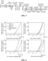
- FIG. 4 illustrates a schematic diagram of a corresponding protection operation situation when faults of different fault types occur at F2 within the region.
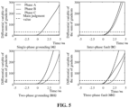
- FIG. 5 illustrates a schematic diagram of a corresponding protection operation situation when faults of different fault types occur at F3 within the region.
- FIG. 6 illustrates a schematic diagram of a protection operation situation when faults of different fault types occur at F4 within the region.
- FIG. 7 illustrates a schematic diagram of a protection operation situation when faults of different fault types occur at F1 outside the region.
- Table 1 provides the differences between abrupt change characteristic values of protection of faults of different fault types at the positions of F2, F3 and F4 within the region and at the positions of F1 and F5 outside the region at the time of 5ms.
- the proposed protection principle has a good operation performance in different scenarios (different fault types and different fault positions).
- the difference between the abrupt change characteristic values of the fault phase is greater than the setting value of the protection criterion within 5ms, and the protection reliably operates.
- both the fault phase and the non-fault phase do not exceed the fixed value, and the protection does not operate, which verifies effectiveness of the proposed protection.
- the proposed protection may still reliably reflect the fault in a scenario of a high-resistance fault of 100 ⁇ .
- the maximum transition resistance of the 220kV system is 100Q, the above results may basically satisfy a good performance of the proposed protection in a scenario of a high-resistance fault.
- Table 3 provides the operation performance of the protection after 5ms in different noise scenarios when a fault occurs at F3.
- the increase of noise has a small influence on the fault phase, and the protection may correctly reflect the fault.
- the increase of noise will lead to a difference between the currents on both sides, which will lead to an increasing trend of the differential variable of the singular value, but it is still far below the setting value.
- the protection may still distinguish the fault type correctly, which may prove that the proposed method has a good anti-noise capacity.
- the operation performance of the protection method provided by the embodiments of the present disclosure is compared with the protection method of the conventional differential protection method (e.g., B in FIG. 8 ).
- the protection starting speed of the conventional differential protection based on the power frequency is slow within 5ms, and there is an obvious trend of falling back in phase A at 5ms.
- the ratio of the differential current of the protection of the exit to the braking current barely exceeds the setting value, the sensitivity seriously decreases, and there is a risk of failure to actuate.
- the new protection principle proposed herein has faster fault response and higher sensitivity within 5ms, which may quickly identify faults and may still ensure a normal performance in the scenarios of the noise and the resistance grounding.
- FIG. 9 is a schematic diagram of a structure of a fault identification system 900 based on full-time-domain abrupt change information according to an implementation of the present disclosure.
- the fault identification system 900 based on the full-time-domain abrupt change information provided by the implementation of the present disclosure includes a fault current acquisition unit 901, an abrupt change characteristic value calculation unit 902 and a fault type determination unit 903.
- the fault current acquisition unit 901 is configured to collect, when a high-voltage AC line fails, current signals on a wind farm side and a flexible DC side, to acquire a respective fault current of each phase on the wind farm side and the flexible DC side.
- the abrupt change characteristic value calculation unit 902 is configured to: for each fault current of a respective phase on the wind farm side and the flexible DC side, construct a respective multi-order matrix according to the fault current of the phase on the wind farm side and the flexible DC side, and calculate, according to the multi-order matrix, a respective abrupt change characteristic value corresponding to the fault current of the phase on the wind farm side and the flexible DC side.
- the fault type determination unit 903 is configured to determine a respective fault type according to a preset criterion and the abrupt change characteristic value corresponding to the fault current of the phase on the wind farm side and the flexible DC side.
- i mmc ⁇ E f cos ⁇ t + ⁇ ⁇ Z eq + m E f Z eq + i w ⁇ cos ⁇ ⁇ t + ⁇ ⁇ ⁇
- i w ⁇ denotes a fault current of a phase ⁇ on the wind farm side.
- i d * denotes a preset current reference value of a d-axis
- i q * denotes a preset current reference value of a q-axis.
- ⁇ PLL denotes a fundamental angular frequency.
- ⁇ ⁇ denotes an initial phase angle.
- ⁇ d denotes a damped natural frequency
- ⁇ d ⁇ n (1- ⁇ 2 ) 1/2
- ⁇ n denotes a natural oscillation angular frequency when a damping of the second-order system is zero
- ⁇ n ( k ii / L ) 1/2
- ⁇ denotes a damping angle of a system
- ⁇ arctan((1- ⁇ 2 ) 1/2 / ⁇ ).
- P denotes a single-phase output active power.
- u d denotes a voltage of the d-axis.
- i d 0 denotes an initial current of the d-axis.
- t denotes fault time.
- k ip denotes a ratio of a current control loop.
- k ii denotes an integral time constant.
- L denotes a bridge arm inductance.
- i mmc ⁇ denotes a fault current of the phase ⁇ on the flexible DC side.
- E f denotes an electric potential within a converter.
- Z eq denotes an equivalent impedance.
- ⁇ denotes an angular frequency of a positive sequence current
- ⁇ - denotes an angular frequency of a negative sequence current.
- m denotes a ratio coefficient related to a short-circuit type.
- ⁇ ⁇ - denotes an initial phase angle of the negative sequence current.
- the abrupt change characteristic value calculation unit 902 is further configured to perform the following operations for the fault current of the phase on the wind farm side and the flexible DC side to acquire the abrupt change characteristic value corresponding to the fault current of the phase on the wind farm side and the flexible DC side.
- the multi-order matrix I T is transformed into expressions of row vectors and column vectors.
- G denotes the abrupt change characteristic value corresponding to the fault current of the phase.
- Gx denotes the horizontal gradient matrix
- Gy denotes the vertical gradient matrix.
- Gx ( i , j ) denotes an element in an i-th row and a j-th column of the horizontal gradient matrix.
- Gy ( i , j ) denotes an element in an i-th row and a j-th column of the vertical gradient matrix.
- the fault type determination unit 903 is further configured to: for any phase, if fault currents on the wind farm side and the flexible DC side corresponding to the phase meet the preset criterion, determine a fault type of the phase as an in-region fault; and
- the fault type of the phase as an out-of-region fault.
- G 1 denotes the abrupt change characteristic value corresponding to the fault current of the phase on the wind farm side
- G 2 denotes the abrupt change characteristic value corresponding to the fault current of the phase on the flexible DC side
- G set denotes a preset setting value.
- the fault type determination unit 903 is further configured to: determine a phase with the fault type of the in-region fault as a fault phase, and protect an exit according to the number of the fault phases; and if the number of the fault phases is less than or equal to a preset number, control a relay protection apparatus to send a fault phase trip instruction to control the fault phase to trip and control a non-fault phase to operate normally; and if the number of the fault phases is greater than the preset number, control the relay protection apparatus to send a three-phase trip instruction to control all of three phases to trip.
- FIG. 10 is a schematic diagram of a structure of an electronic device 1000 according to an implementation of the present disclosure.
- the electronic device 1000 includes a memory 1001, a processor 1002, and a computer program stored in the memory 1001 and executable on the processor 1002.
- the processor 1002 when executing the computer program, implements the operations of the above fault identification method as shown in FIG. 1 .
- the present disclosure provides a computer-readable storage medium having stored thereon a computer program.
- the computer program when executed by a processor, implements the operations of the above fault identification method as shown in FIG. 1 .
- the embodiments of the present disclosure may be provided as methods, systems, or computer program products. Therefore, the present disclosure may adopt the form of a fully hardware embodiment, the form of a fully software embodiment, or the form of combining embodiments in software and hardware aspects. Furthermore, the present disclosure may adopt the form of a computer program product implemented on one or more computer-usable storage media (including a disk memory, a CD-ROM, an optical memory, or the like, but not limited thereto) that contain computer-usable program codes therein.
- computer-usable storage media including a disk memory, a CD-ROM, an optical memory, or the like, but not limited thereto
- These computer program instructions may also be stored in a computer-readable memory capable of directing a computer or other programmable data processing devices to operate in a specific manner, such that the instructions stored in the computer-readable memory produce a manufactured article including an instruction apparatus that implements the functions specified in one or more processes of the flowchart and/or one or more blocks of the block diagram.
- These computer program instructions may also be loaded onto a computer or other programmable data processing devices, so as to perform a series of operations on the computer or other programmable devices to generate computer-implemented processing, so that the instructions executed on the computer or other programmable devices provide operations for implementing the functions specified in one or more processes of the flowchart and/or one or more blocks of the block diagram.
- the present disclosure provides a fault identification method based on full-time-domain abrupt change information, a system, an electronic device, and a computer-readable storage medium.
- the high-voltage AC line fails, the current signals on the wind farm side and the flexible DC side are collected, and a respective fault current of each phase on the wind farm side and the flexible DC side are acquired.
- a respective multi-order matrix is constructed according to the fault current of the phase on the wind farm side and the flexible DC side, and according to the multi-order matrixes, a respective abrupt change characteristic value corresponding to the fault current of the phase on the wind farm side and the flexible DC side is calculated.
- a respective fault type is determined according to a preset criterion and the abrupt change characteristic value corresponding to the fault current of the phase on the wind farm side and the flexible DC side.
- the current signals of the phases on both sides of the line are used to construct multi-order matrixes respectively.
- the characteristic that the multi-order matrix may quickly amplify the proportion of abrupt change signals and the advantage that the matrix gradient may accurately represent the degree of the abrupt change of data are comprehensively used to construct the protection criterion, so as to achieve the high-speed and reliable fault identification, thereby solving the problem of the risk of sensitivity decrease of conventional protection and the risk of incorrect operation in the new power system.
- the present disclosure may adapt to a scenario of access and delivery of multiple types of new energy power supplies without depending on the power frequency quantity, and have a capacity to withstand the transition resistance and noise and a rapid responsiveness, which has an important engineering significance for the high proportion consumption of the future new energy and the safe operation of the power grid, and provides the premise and guarantee for further development of the new energy power electronic system with a high proportion in the future.
Landscapes
- Physics & Mathematics (AREA)
- General Physics & Mathematics (AREA)
- Engineering & Computer Science (AREA)
- Mathematical Physics (AREA)
- Theoretical Computer Science (AREA)
- Artificial Intelligence (AREA)
- Evolutionary Computation (AREA)
- Power Engineering (AREA)
- Supply And Distribution Of Alternating Current (AREA)
- Emergency Protection Circuit Devices (AREA)
Abstract
Description
- The present disclosure is based on and claims priority to
Chinese Patent Application No. 202210717823.0 filed on June 23, 2022 - The present disclosure relates to the field of power system protection technology, and relates to, but is not limited to, a fault identification method and a system based on full-time-domain abrupt change information, an electronic device, and a computer-readable storage medium.
- With the increasing proportion of new energy such as wind power and photovoltaic, the scale of the power grid is continuously expanding, and security of China's new power system is facing serious challenges. High proportion of new energy has become an important characteristic of the new power system. In the new power system, since a large number of power electronic converters are incorporated into the power grid, the fault transient process is closely related to the control strategy and parameters of the power electronic device, the amplitude of the short-circuit current is limited, the phase angle of the short-circuit current is controlled, and the content of non-characteristic harmonic increases significantly, which would lead to a certain threat to the reliability and sensitivity of the conventional power frequency based relay protection, make the performance of the conventional differential protection decrease, and seriously affects the safe operation of the new energy power system. At present, according to different types of fault information, existing protection principles may be subdivided into full-time-domain information protection and frequency-domain information protection. The full-time-domain information protection represents the difference between the current transient waveforms of the new energy station and the current transient waveforms of the power grid by cosine similarity, Spearman grade correlation coefficient, Pearson correlation coefficient, or the like. However, such method completely depends on the voltage and current on both sides of the line. When the output of the new energy station is small, or when the new energy station is incorporated into the weak power grid, the overall current amplitude is small, and there is a risk of performance decrease of the protection, or even a risk of failure to actuate. As for the protection of the frequency-domain information, the conventional protection method using power frequency quantity information needs to extract the power frequency quantity information from sample values of the current and voltage after the fault, so as to form a protection criterion. However, since line fault information adopted by such method is mainly the power frequency quantity, it is easy to be affected by characteristics of the new energy station, such as the limited amplitude of the short-circuit current, the controlled phase angle, the frequency deviation, or the like, which leads to the decrease of the protection performance. Therefore, a new fault identification method is urgently needed when the high-voltage Alternating Current (AC) line fails.
- The present disclosure proposes a fault identification method and a system based on full-time-domain abrupt change information, so as to solve the problem of how to achieve high-voltage AC line fault identification efficiently and improve the protection capacity of the power system.
- In order to solve the above problem, according to an aspect of the present disclosure, a fault identification method based on full-time-domain abrupt change information is provided. The method includes the following operations.
- When a high-voltage AC line fails, current signals on a wind farm side and a flexible Direct Current (DC) side are collected to acquire a respective fault current of each phase on the wind farm side and the flexible DC side.
- For each fault current of a respective phase on the wind farm side and the flexible DC side, a respective multi-order matrix is constructed according to the fault current of the phase on the wind farm side and the flexible DC side, and a respective abrupt change characteristic value corresponding to the fault current of the phase on the wind farm side and the flexible DC side is calculated according to the multi-order matrix.
- A respective fault type is determined according to a preset criterion and the abrupt change characteristic value corresponding to the fault current of the phase on the wind farm side and the flexible DC side.
- In some embodiments, the fault current of the phase on the wind farm side is:

- The fault current of the phase on the flexible DC side is:

- Here, iwϕ denotes a fault current of a phase ϕ on the wind farm side.


- Here, immcϕ denotes a fault current of the phase ϕ on the flexible DC side. Ef denotes an electric potential within a converter. Zeq denotes an equivalent impedance. ω denotes an angular frequency of a positive sequence current, and ω - denotes an angular frequency of a negative sequence current. m denotes a ratio coefficient related to a short-circuit type. θϕ- denotes an initial phase angle of the negative sequence current.
- In some embodiments, the operation that the respective multi-order matrix is constructed according to the fault current of the phase on the wind farm side and the flexible DC side, and the respective abrupt change characteristic value corresponding to the fault current of the phase on the wind farm side and the flexible DC side is calculated according to the multi-order matrix includes the following operations.
- The following operations are performed for the fault current of the phase on the wind farm side and the flexible DC side to acquire the abrupt change characteristic value corresponding to the fault current of the phase on the wind farm side and the flexible DC side.
- Sample values of a fault current of any phase are determined as an one-dimensional array, and a current signal composed of N sampling points within sampling time is denoted as I = {i 1,i 2,i 3,···,iN }. The multi-order matrix is:

- The multi-order matrix IT is transformed into expressions of row vectors and column vectors. The expression of the column vectors is IT = {I 1,I 2,I 3,···,IN }, and internal elements of the first column vector are I 1 = {i 1,i 2,i 3,···,iN } T . The expression of the row vectors is IT = {I 1 T ,I 2 T ,I 3 T ,···,IN T } T , and internal elements of the first row vector are I 1 T = {i 1,i 2,i 3,···,iN }.
- A horizontal gradient matrix corresponding to the multi-order matrix with the expression of the column vectors is calculated, including:

- A vertical gradient matrix corresponding to the multi-order matrix with the expression of the row vectors is calculated, including:

- The abrupt change characteristic value is calculated according to the horizontal gradient matrix and the vertical gradient matrix, including:

- Here, G denotes the abrupt change characteristic value corresponding to the fault current of the phase. Gx denotes the horizontal gradient matrix, and Gy denotes the vertical gradient matrix. Gx(i, j) denotes an element in an i-th row and a j-th column of the horizontal gradient matrix. Gy(i, j) denotes an element in an i-th row and a j-th column of the vertical gradient matrix.
- In some embodiments, the operation that the respective fault type is determined according to the preset criterion and the abrupt change characteristic value corresponding to the fault current of the phase on the wind farm side and the flexible DC side includes the following operations.
- For any phase, if fault currents on the wind farm side and the flexible DC side corresponding to the phase meet the preset criterion, a fault type of the phase is determined as an in-region fault.
- If the fault currents on the wind farm side and the flexible DC side corresponding to the phase do not meet the preset criterion, the fault type of the phase is determined as an out-of-region fault.
- The preset criterion includes ΔG=|G 1 -G 2|>Gset. Here, G 1 denotes the abrupt change characteristic value corresponding to the fault current of the phase on the wind farm side, G 2 denotes the abrupt change characteristic value corresponding to the fault current of the phase on the flexible DC side, and Gset denotes a preset setting value.
- In some embodiments, a phase with the fault type of an in-region fault is determined as a fault phase, and an exit is protected according to the number of fault phases.
- Here, if the number of the fault phases is less than or equal to a preset number, a relay protection apparatus is controlled to send a fault phase trip instruction to control the fault phase to trip and control a non-fault phase to operate normally. If the number of the fault phases is greater than the preset number, the relay protection apparatus is controlled to send a three-phase trip instruction to control all of three phases to trip.
- The present disclosure provides a fault identification system based on full-time-domain abrupt change information. The system includes a fault current acquisition unit, an abrupt change characteristic value calculation unit and a fault type determination unit.
- The fault current acquisition unit is configured to collect, when a high-voltage AC line fails, current signals on a wind farm side and a flexible DC side, to acquire a respective fault current of each phase on the wind farm side and the flexible DC side.
- The abrupt change characteristic value calculation unit is configured to: for each fault current of a respective phase on the wind farm side and the flexible DC side, construct a respective multi-order matrix according to the fault current of the phase on the wind farm side and the flexible DC side, and calculate, according to the multi-order matrix, a respective abrupt change characteristic value corresponding to the fault current of the phase on the wind farm side and the flexible DC side.
- The fault type determination unit is configured to determine a respective fault type according to a preset criterion and the abrupt change characteristic value corresponding to the fault current of the phase on the wind farm side and the flexible DC side.
- In some embodiments, at the fault current acquisition unit, the fault current of the phase on the wind farm side is:

- The fault current of the phase on the flexible DC side is:

- Here, iwϕ denotes a fault current of a phase ϕ on the wind farm side.


- Here, immcϕ denotes a fault current of the phase ϕ on the flexible DC side. Ef denotes an electric potential within a converter. Zeq denotes an equivalent impedance. ω denotes an angular frequency of a positive sequence current, and ω - denotes an angular frequency of a negative sequence current. m denotes a ratio coefficient related to a short-circuit type. θ ϕ- denotes an initial phase angle of the negative sequence current.
- In some embodiments, the abrupt change characteristic value calculation unit is further configured to perform the following operations for the fault current of the phase on the wind farm side and the flexible DC side to acquire the abrupt change characteristic value corresponding to the fault current of the phase on the wind farm side and the flexible DC side.
- Sample values of a fault current of any phase are determined as an one-dimensional array, and a current signal composed of N sampling points within sampling time is denoted as I = {i 1,i 2,i 3,···,iN }. The multi-order matrix is:

- The multi-order matrix IT is transformed into expressions of row vectors and column vectors. The expression of the column vectors is IT = {I 1,I 2,I 3,···,IN }, and internal elements of the first column vector are I 1 = {i 1,i 2,i 3,···,iN } T . The expression of the row vectors is IT = {I 1 T ,I 2 T ,I 3 T ,···,IN T } T , and internal elements of the first row vector are I 1 T = {i 1,i2,i 3,···,iN }.
- A horizontal gradient matrix corresponding to the multi-order matrix with the expression of the column vectors is calculated, including:

- A vertical gradient matrix corresponding to the multi-order matrix with the expression of the row vectors is calculated, including:

- The abrupt change characteristic value is calculated according to the horizontal gradient matrix and the vertical gradient matrix, including:

- Here, G denotes the abrupt change characteristic value corresponding to the fault current of the phase. Gx denotes the horizontal gradient matrix, and Gy denotes the vertical gradient matrix. Gx(i, j) denotes an element in an i-th row and a j-th column of the horizontal gradient matrix. Gy(i, j) denotes an element in an i-th row and a j-th column of the vertical gradient matrix.
- In some embodiments, the fault type determination unit is further configured to: for any phase, if fault currents on the wind farm side and the flexible DC side corresponding to the phase meet the preset criterion, determine a fault type of the phase as an in-region fault; and
- if the fault currents on the wind farm side and the flexible DC side corresponding to the phase do not meet the preset criterion, determine the fault type of the phase as an out-of-region fault.
- The preset criterion includes ΔG=|G 1-G 2|>Gset. Here, G 1 denotes the abrupt change characteristic value corresponding to the fault current of the phase on the wind farm side, G 2 denotes the abrupt change characteristic value corresponding to the fault current of the phase on the flexible DC side, and Gset denotes a preset setting value.
- In some embodiments, the fault type determination unit is further configured to: determine a phase with the fault type of the in-region fault as a fault phase, and protect an exit according to the number of the fault phases; and
- if the number of the fault phases is less than or equal to a preset number, control a relay protection apparatus to send a fault phase trip instruction to control the fault phase to trip and control a non-fault phase to operate normally; and if the number of the fault phases is greater than the preset number, control the relay protection apparatus to send a three-phase trip instruction to control all of three phases to trip.
- The present disclosure provides an electronic device including a memory, a processor, and a computer program stored in the memory and executable on the processor. The processor, when executing the computer program, implements the operations of the above method.
- The present disclosure provides a computer-readable storage medium having stored thereon a computer program. The computer program, when executed by a processor, implements the operations of the above method.
- The present disclosure provides a fault identification method based on full-time-domain abrupt change information, a system, an electronic device, and a computer-readable storage medium. When the high-voltage AC line fails, the current signals on the wind farm side and the flexible DC side are collected, and a respective fault current of each phase on the wind farm side and the flexible DC side are acquired. For each fault current of a respective phase on the wind farm side and the flexible DC side, a respective multi-order matrix is constructed according to the fault current of the phase on the wind farm side and the flexible DC side, and according to the multi-order matrixes, a respective abrupt change characteristic value corresponding to the fault current of the phase on the wind farm side and the flexible DC side is calculated. A respective fault type is determined according to a preset criterion and the abrupt change characteristic value corresponding to the fault current of the phase on the wind farm side and the flexible DC side. According to the method of the present disclosure, the current signals of the phases on both sides of the line are used to construct multi-order matrixes respectively. The characteristic that the multi-order matrix may quickly amplify the proportion of abrupt change signals and the advantage that the matrix gradient may accurately represent the degree of the abrupt change of data are comprehensively used to construct the protection criterion, so as to achieve the high-speed and reliable fault identification, thereby solving the problem of the risk of sensitivity decrease of conventional protection and the risk of incorrect operation in the new power system. The present disclosure may adapt to a scenario of access and delivery of multiple types of new energy power supplies without depending on the power frequency quantity, and have a capacity to withstand the transition resistance and noise and a rapid responsiveness, which has an important engineering significance for the high proportion consumption of the future new energy and the safe operation of the power grid, and provides the premise and guarantee for further development of the new energy power electronic system with a high proportion in the future.
- Exemplary implementations of the present disclosure may be more completely understood with reference to the following drawings.
-
FIG. 1 is a flowchart of a fault identification method based on full-time-domain abrupt change information provided by an implementation of the present disclosure. -
FIG. 2 is a flowchart of protection provided by an implementation of the present disclosure. -
FIG. 3 is a schematic diagram of incorporating a fan incorporated an AC system provided by an implementation of the present disclosure. -
FIG. 4 is a schematic diagram of a protection operation situation when different fault types of faults occur at F2 within a region provided by an implementation of the present disclosure. -
FIG. 5 is a schematic diagram of a protection operation situation when different fault types of faults occur at F3 within a region provided by an implementation of the present disclosure. -
FIG. 6 is a schematic diagram of a protection operation situation when different fault types of faults occur at F4 within a region provided by an implementation of the present disclosure. -
FIG. 7 is a schematic diagram of a protection operation situation when different fault types of faults occur at F1 outside a region provided by an implementation of the present disclosure. -
FIG. 8 is a comparison diagram of protection effects of a protection method provided by an implementation of the present disclosure and a conventional protection method. -
FIG. 9 is a schematic diagram of a structure of a fault identification system based on full-time-domain abrupt change information provided by an implementation of the present disclosure. -
FIG. 10 is a schematic diagram of a structure of an electronic device provided by an implementation of the present disclosure. - Exemplary implementations of the present disclosure are now introduced with reference to the drawings. However, the present disclosure may be implemented in many different forms and is not limited to the embodiments described herein. The embodiments are provided to fully and completely disclose the present disclosure and to fully communicate the scope of the present disclosure to those skilled in the technical field to which they belong. Terms in the exemplary implementations expressed in the drawings are not limitations on the present disclosure. In the drawings, the same units/components use the same reference.
- Unless otherwise illustrated, terms used herein (including technical terminologies) have general meanings understood by those skilled in the technical field to which they belong. In addition, it is to be understood that a term limited by a commonly used dictionary should be understood to have a meaning consistent with the context of the related field thereof, and should not be understood as an idealized or too formal meaning.
- In the new power system, since the fault characteristics are affected by the control strategy of the power electronic apparatus, the short-circuit current presents characteristics such as limited amplitude, non-power frequency, controlled phase angle, or the like, which are completely different from those of a synchronous generator. As a result, it is difficult for conventional differential protection to quickly extract a continuous and stable power frequency component in a scenario that the short-circuit current is controlled, so that a risk of sensitivity decrease or even incorrect operation will occur, thereby affecting the safe operation of the power system. Therefore, the study of a new protection principle that is not affected by the control of the power electronic apparatus is of great significance for safe and stable operation of large-scale new energy grid-connection in the future.
FIG. 1 is a flowchart of afault identification method 100 based on full-time-domain abrupt change information according to an implementation of the present disclosure. As shown inFIG. 1 , according to the fault identification method based on the full-time-domain abrupt change information provided by the implementation of the present disclosure, the current signals of the phases on both sides of the line are used to construct multi-order matrixes respectively. The characteristic that the multi-order matrix may quickly amplify the proportion of abrupt change signals and the advantage that the matrix gradient may accurately represent the degree of the abrupt change of data are comprehensively used to construct the protection criterion, so as to achieve the high-speed and reliable fault identification, thereby solving the problem of the risk of sensitivity decrease of conventional protection and the risk of incorrect operation in the new power system. The present disclosure may adapt to a scenario of access and delivery of multiple types of new energy power supplies without depending on the power frequency quantity, and have a capacity to withstand the transition resistance and noise and a rapid responsiveness, which has an important engineering significance for the high proportion consumption of the future new energy and the safe operation of the power grid, and provides the premise and guarantee for further development of the new energy power electronic system with a high proportion in the future. - Referring to
FIG. 1 , thefault identification method 100 based on the full-time-domain abrupt change information provided by the implementation of the present disclosure may be achieved by the following operations. - In
operation 101, when a high-voltage AC line fails, current signals on a wind farm side and a flexible DC side are collected to acquire a respective fault current of each phase on the wind farm side and the flexible DC side. - In the embodiments of the present disclosure, the fault current of the phase on the wind farm side may be represented by the following
formula 1.
- The fault current of the phase on the flexible DC side may be represented by the following
formula 2.
- Here, iwϕ denotes a fault current of a phase ϕ on the wind farm side.


- Here, immcϕ denotes a fault current of the phase ϕ on the flexible DC side. Ef denotes an electric potential within a converter. Zeq denotes an equivalent impedance. ω denotes an angular frequency of a positive sequence current, and ω - denotes an angular frequency of a negative sequence current. m denotes a ratio coefficient related to a short-circuit type. θ ϕ- denotes an initial phase angle of the negative sequence current.
- In the embodiments of the present disclosure, firstly, fault characteristics of in-region and out-of-region faults of the AC line on which the new energy is sent through the grid-connection on the flexible DC side are analyzed to clarify characteristics of in-region and out-of-region fault currents. Then, single-phase current signals collected within time windows on both sides are constructed into a multi-order matrix. The wind power converter is the only power outlet of the permanent magnet fan. Due to a limited overcurrent capacity, in order to protect the power electronic components of the converter, the control system mainly uses amplitude limit control and negative sequence current control. The short-circuit current of each phase on the wind farm side may be represented by the
above formula 1. - As shown in the
above formula 1, the short-circuit current of the wind farm is controlled by the reference values of the currents of the d-axis and q-axis of the control system of the converter, and the wind farm is equivalent to a controlled current source. Due to a limited capacity of the converter to withstand overcurrent, the short-circuit current is generally 1.5-2 times the maximum rated current. Therefore, the wind farm has a characteristic of limited amplitude of the fault current. - In some embodiments, since the converter at the sending end on the flexible DC side is coupled to a controlled current source, it is generally controlled by AC voltage-frequency and is equivalent to a controlled voltage source. The fault current before the converter at the sending end on the flexible DC side is blocked may be represented by the
above formula 2. - As can be known from the
above formula 2, when a fault occurs, the short-circuit current provided by the flexible DC converter has a positive sequence component and a negative sequence component simultaneously. The converter is equivalent to a controlled voltage source, and the amplitude of the short-circuit current depends on the equivalent internal potential and equivalent impedance of the flexible DC converter. - According to the above analysis of the fault characteristics of the converter, it can be known that the fault current of the converter has a limited amplitude and lacks a continuous and stable power frequency component, which seriously affects the correct fault identification of the conventional current differential protection principle. Sensitivity will decrease during the calculation process of the protection apparatus, and there is a risk of incorrect operation. In addition, different converter control reflects different control response characteristics, which thus determines that the abrupt change characteristics of the short-circuit current after the fault are different and are all different from those of a conventional synchronous machine.
- In
operation 102, for each fault current of a respective phase on the wind farm side and the flexible DC side, a respective multi-order matrix is constructed according to the fault current of the phase on the wind farm side and the flexible DC side, and a respective abrupt change characteristic value corresponding to the fault current of the phase on the wind farm side and the flexible DC side is calculated according to the multi-order matrix. - In the embodiments of the present disclosure, the operation that the respective multi-order matrix is constructed according to the fault current of the phase on the wind farm side and the flexible DC side, and the respective abrupt change characteristic value corresponding to the fault current of the phase on the wind farm side and the flexible DC side is calculated according to the multi-order matrix includes the following operations.
- The following operations are performed for the fault current of the phase on the wind farm side and the flexible DC side to acquire the abrupt change characteristic value corresponding to the fault current of the phase on the wind farm side and the flexible DC side.
- Sample values of a fault current of any phase are determined as an one-dimensional array, and a current signal composed of N sampling points within sampling time is denoted as I = {i 1,i 2,i 3,···,iN }. The multi-order matrix may be represented by the following formula 3.

- The multi-order matrix IT is transformed into expressions of row vectors and column vectors. The expression of the column vectors is IT = {I 1,I 2,I 3,···,IN }, and internal elements of the first column vector are I 1 = {i 1,i 2,i 3,···,iN } T . The expression of the row vectors is IT = {I 1 T ,I 2 T ,I 3 T ,···,IN T } T , and internal elements of the first row vector are I 1 T = {i 1,i 2,i 3,···,iN }.
- A horizontal gradient matrix corresponding to the multi-order matrix with the expression of the column vectors is calculated. The horizontal gradient matrix may be obtained by the following formula 4.

- A vertical gradient matrix corresponding to the multi-order matrix with the expression of the row vectors is calculated. The vertical gradient matrix may be obtained by the following
formula 5.
- The abrupt change characteristic value is calculated according to the horizontal gradient matrix and the vertical gradient matrix. The abrupt change characteristic value may be obtained by the following formula 6.

- Here, G denotes the abrupt change characteristic value corresponding to the fault current of the phase. Gx denotes the horizontal gradient matrix, and Gy denotes the vertical gradient matrix. Gx(i, j) denotes an element in an i-th row and a j-th column of the horizontal gradient matrix. Gy(i, j) denotes an element in an i-th row and a j-th column of the vertical gradient matrix.
- In the embodiments of the present disclosure, current sample values of any phase on both sides of the line may be regarded as an one-dimensional array, i.e., a current signal of N sampling points during a period of time constitutes the one-dimensional data I, which is denoted as I = {i 1,i 2,i 3,···,iN }.
- The obtained one-dimensional data I constituted by the current signal of the N sampling points is improved to obtain a multi-order matrix IT. The improvement manner is as follows.
- An empty matrix of N×N is constructed, and all signal elements in the first row of the matrix are arranged orderly in a chronological order starting from i 0. Due to the symmetry of the matrix, like the first row, the first column is also arranged orderly starting from i 0. From the second row, the element at each position is the same as the element at its upper-left corner until the entire N×N matrix is filled. The matrix adopts a symmetric configuration, which makes it conform to the definition of a symmetric matrix IT =IT T , and each element is the same as the element at its upper-left corner. When all signal elements in the matrix are arranged according to the rule, the multi-order matrix IT is obtained.
- It is to be noted that when a fault occurs, there will be a short-term abrupt change of the current. Therefore, the current signal after the fault will have a larger step jump compared to the previous signal. In addition, the concept of matrix gradient is introduced in order to represent the degree of the abrupt change with specific numerical values.
- The matrix gradient is divided into transverse gradient and longitudinal gradient, which mainly reflects the degree of change between adjacent elements in the matrix. Taking the multi-order matrix IT as an example, it is converted into an expression of column vectors.
- The expression of the column vectors is IT = {I 1,I 2,I 3 ,···,IN }, and the internal elements of the first column vector are I 1 = {i 1,i 2,i 3,···,iN } T . The difference between the first column vector and the next column vector of the current matrix is divided by 1 to obtain the first column vector of the horizontal gradient matrix. The average of the differences between the n-th column vector in the middle and the current column vectors on both sides is taken as the n-th column vector of the horizontal gradient matrix. The difference between the last column vector and the previous column vector is taken as the last column vector of the horizontal gradient matrix. The expression of the horizontal gradient matrix Gx is as follows.

- Similarly, the expression of the row vectors is IT = {I 1 T ,I 2 T ,I 3 T ,···,IN T } T , and the internal elements of the first row vector are I 1 T = {i 1,i 2,i 3,···,iN }. Then, the difference between the first row vector and the next row vector of the current matrix is divided by 1 to obtain the first row vector of the vertical gradient matrix. The average of the differences between the n-th row vector in the middle and the current row vectors on both sides is taken as the n-th row vector of the vertical gradient matrix. The difference between the last row vector and the previous row vector is taken as the last row vector of the vertical gradient matrix. The expression of the vertical gradient matrix Gy is as follows.

- For any phase, after the horizontal gradient matrix Gx and the vertical gradient matrix Gy are acquired, absolute values are taken for the obtained horizontal gradient matrix Gx and the vertical gradient matrix Gy, and the sum of all elements in the two matrixes is calculated as the abrupt change characteristic value of the signal collected within the time window. Then, the abrupt change characteristic value G corresponding to the current signal of any phase may be obtained, which is expressed as follows.

- That is, the abrupt change characteristic value G of each time window is taken to reflect the abrupt change characteristic value of the signal. Here, G denotes the abrupt change characteristic value corresponding to the fault current of the phase. Gx denotes the horizontal gradient matrix, and Gy denotes the vertical gradient matrix. Gx(i, j) denotes an element in the i-th row and the j-th column of the horizontal gradient matrix. Gy(i, j) denotes an element in the i-th row and the j-th column of the vertical gradient matrix.
- In the embodiments of the present disclosure, the fault current of the phase on the wind farm side and the flexible DC side corresponds to an abrupt change characteristic value.
- In
operation 103, a respective fault type is determined according to a preset criterion and the abrupt change characteristic value corresponding to the fault current of the phase on the wind farm side and the flexible DC side. - In the embodiments of the present disclosure, the operation that the respective fault type is determined according to the preset criterion and the abrupt change characteristic value corresponding to the fault current of the phase on the wind farm side and the flexible DC side includes the following operations.
- For any phase, if fault currents on the wind farm side and the flexible DC side corresponding to the phase meet the preset criterion, a fault type of the phase is determined as an in-region fault.
- If the fault currents on the wind farm side and the flexible DC side corresponding to the phase do not meet the preset criterion, the fault type of the phase is determined as an out-of-region fault.
- The preset criterion includes ΔG=|G 1-G 2|>Gset. Here, G 1 denotes the abrupt change characteristic value corresponding to the fault current of the phase on the wind farm side, G 2 denotes the abrupt change characteristic value corresponding to the fault current of the phase on the flexible DC side, and Gset denotes a preset setting value.
- In other embodiments of the present disclosure, a phase with the fault type of an in-region fault is determined as a fault phase, and an exit is protected according to the number of the fault phases.
- Here, if the number of the fault phases is less than or equal to a preset number, a relay protection apparatus is controlled to send a fault phase trip instruction to control the fault phase to trip and control a non-fault phase to operate normally. If the number of the fault phases is greater than the preset number, the relay protection apparatus is controlled to send a three-phase trip instruction to control all of three phases to trip.
- In the embodiments of the present disclosure, it is necessary to make use of the different multi-dimensional abrupt change characteristic values of the current signal when an in-region fault occurs to construct a criterion, and then to identify the fault type by comparing the size relationship between the actual operational value in the criterion and the setting value, so that corresponding protection measures are enabled according to the fault type.
- During the normal steady state operation, power of the wind farm completely flows to the flexible DC side through the line. In such case, all current flowing through the line is through-current, and AC currents collected on both sides of the line are the same sine wave. Therefore, the abrupt change characteristic values G of the current signals collected on both sides in the same time window should also be basically the same.
- In case of an in-region fault, due to the difference in control strategy and adjustment speed, the fault currents on both sides will be greatly adjusted in a short time after the fault occurs. The abrupt change characteristic value of the whole time window will change in a short time due to the collected fault point, and the changes in the current signals collected on both sides are different. The calculated abrupt change characteristic values G will be significantly different.
- In case of an out-of-region fault, the through-current also flows through the protected line. Therefore, the abrupt change characteristic values G of the multi-order matrix gradient of the in-phase current signals on both sides should be the same. Theoretically, the difference between the abrupt change characteristic values G of the current signals collected on both sides should approach zero.
- Therefore, according to the above fault characteristic analysis, the protection criterion may be constructed as follows.

- Here, each of G 1 and G 2 denotes a respective one of the abrupt change characteristic values corresponding to the current signals at both ends of the line, and |•| denotes taking the absolute value. Gset denotes the setting value of the main criterion of the protection, which is set according to the maximum amplitude error when the external fault is avoided. Considering that the maximum transmission error of the Current transformer (CT) is ±10% and the capacitor has a small influence on the fault current, the maximum amplitude error on both sides is set to 20%, and a certain margin is retained considering special circumstances. In the embodiments of the present disclosure, in order to ensure that the number of sampling points meets the calculation requirements, the shorter the time window is, the higher the sampling frequency is required. However, it is difficult for an industrial application to achieve a high sampling frequency. Therefore, current signals within a time window of 10ms are adopted to construct a multi-order matrix, and the sum of the absolute values of the matrix gradient is obtained to determine the multi-abrupt change characteristic value.
- In combination with
FIG. 2 , in the embodiments of the present disclosure, the fault type is identified by comparing the size relationship between the actual operational value |G 1 -G 2| of the criterion and the setting value Gset, and corresponding protection measures are enabled according to the fault type. The specific process is as follows. After the protection is started, each set of protection apparatus judges the fault phase by phase, extracts the differential current data 10ms after the fault moment, and performs calculation according to the proposed protection criterion. For any phase, if the formula of the protection criterion is met, i.e., the difference between the multi-dimensional abrupt change characteristic values is greater than the setting value, the fault type is determined to be an in-region fault, and the exit is protected. Otherwise, the fault type is determined to be an out-of-region fault, and the protection is restored. - It is to be noted that after the fault type is determined, a phase with the fault type of the in-region fault is determined to be a fault phase. If the fault phase is a single phase, the relay protection apparatus sends the fault phase trip instruction, and the non-fault phase continues to operate. If two or three phases meet the criterion, the relay protection apparatus sends the three-phase trip instruction to control all the three phases to trip.
- After the large-scale new energy is incorporated into the power grid, the sensitivity of the conventional protection decreases. In order to ensure safe and reliable operation of the system, the method proves that there is an obvious difference between the abrupt change characteristic values in case of in-region and out-of-region faults by theoretical analysis and simulation verification. Finally, a high-voltage AC line protection method adopting the multi-dimensional abrupt change information is proposed. The method provided by the embodiments of the present disclosure solves the problem of the risk of sensitivity decrease and incorrect operation of the conventional protection, which is caused by the fact that the fault current is controlled and can not provide a continuous and stable power frequency component, and the method is applicable to different types of new energy stations. The method provided by the embodiments of the present disclosure has the following characteristics.
- 1) A high speed. The time for protecting the exit is within 5ms.
- 2) High reliability. The protection constructs the protection criterion by the difference between multi-dimensional abrupt change characteristic values of the short-circuit currents on both sides after the region fault, which is not affected by the characteristics of the power supplies on both sides, and may still correctly operate in case of noise greater than 30dB. Compared with the conventional differential protection, in a two-side controlled scenario that the new energy is connected to a flexible DC system, high sensitivity may still be ensured to achieve the reliable operation.
- 3) Strong tolerance for the transition resistance. The protection may still correctly operate in case of transition resistance of 100Q.
- In the following, the implementations of the present disclosure are specifically illustrated with examples.
- The grid-connection system shown in
FIG. 3 , in which a direct-drive wind farm with a rated voltage of 220 kilovolt (kV) is connected to the grid through a ±500kV flexible DC transmission line, is built in a Power Systems Computer Aided Design (PSCAD) or an Electromagnetic Transients including DC (EMTDC). The system capacity is 200 megavolt-ampere (MVA). The wind farm is equivalent to a single fan, and the capacity of the single fan of a wind turbine is 5 million watt (MW). The length of the AC line from the transformer of the wind farm to the converter at the flexible DC sending end is 20 kilometers (km). - As shown in
FIG. 3 , five fault points are set on the AC line. Here, F1 and F5 are out-of-region fault points, and in-region internal faults include an outlet of the protection line on the wind farm side F2, an outlet of the line on the flexible DC side F4, and a fault at the middle point of the line F3. The sampling frequency of the current signal is 4kHz, and the time window is selected to be 10ms. - The setting value should be set to avoid the maximum amplitude error when an external fault occurs. The maximum transmission error of the CT is ±10%, and the maximum amplitude error on both sides is 20%. Although the influence of the capacitor current is small, the influence of the capacitor current is avoided by an adjustable margin. The margin herein is set to 20% and may be adjusted according to actual system parameters. When there is an error of 20% amplitude on both sides, the difference between the abrupt change characteristic values G increases to 30 in case of an external fault. Therefore, the constant value of Gset is set to 30.
-
FIG. 4 illustrates a schematic diagram of a corresponding protection operation situation when faults of different fault types occur at F2 within the region.FIG. 5 illustrates a schematic diagram of a corresponding protection operation situation when faults of different fault types occur at F3 within the region.FIG. 6 illustrates a schematic diagram of a protection operation situation when faults of different fault types occur at F4 within the region.FIG. 7 illustrates a schematic diagram of a protection operation situation when faults of different fault types occur at F1 outside the region. In addition, Table 1 provides the differences between abrupt change characteristic values of protection of faults of different fault types at the positions of F2, F3 and F4 within the region and at the positions of F1 and F5 outside the region at the time of 5ms. - As can be seen from
FIG. 4 to FIG. 7 , the proposed protection principle has a good operation performance in different scenarios (different fault types and different fault positions). In case of an in-region fault, the difference between the abrupt change characteristic values of the fault phase is greater than the setting value of the protection criterion within 5ms, and the protection reliably operates. In case of an out-of-region fault, both the fault phase and the non-fault phase do not exceed the fixed value, and the protection does not operate, which verifies effectiveness of the proposed protection. - In order to verify adaptability to the transition resistance of the proposed protection, taking an in-region fault occurring at F3 as an example, a grounding fault of phase A and a fault between phases B and C in case of the transition resistance of 25Ω, 50Ω, 75Ω and 100Ω are analyzed respectively. Table 2 respectively provides the differential variable of the abrupt change characteristic value of the proposed protection in case of a grounding fault of a single phase and a fault between two phases through the transition resistance.
- As can be seen from Table 2, with the increase of the transition resistance, the degree of abrupt change of the current signal gradually decreases, the difference between the abrupt change characteristic values of the current signals on both sides decreases, and thus the differential variable of the abrupt change characteristic value decreases. Although there is a trend of sensitivity decrease, the proposed protection may still reliably reflect the fault in a scenario of a high-resistance fault of 100Ω. Considering that the maximum transition resistance of the 220kV system is 100Q, the above results may basically satisfy a good performance of the proposed protection in a scenario of a high-resistance fault.
- Table 3 provides the operation performance of the protection after 5ms in different noise scenarios when a fault occurs at F3. As can be seen from Table 3, the increase of noise has a small influence on the fault phase, and the protection may correctly reflect the fault. For the non-fault phase, the increase of noise will lead to a difference between the currents on both sides, which will lead to an increasing trend of the differential variable of the singular value, but it is still far below the setting value. In a scenario of high noise of 30dB, the protection may still distinguish the fault type correctly, which may prove that the proposed method has a good anti-noise capacity.
Table 1 Position of the fault Fault type Differential variable of the sum of matrix gradients phase A phase B phase C F1 outside the region AG 1.1093 0.3083 2.6746 BC 0.0683 0.5035 2.7304 BCG 0.0326 0.7884 3.2169 ABC 1.3819 0.3360 2.8849 F2 within the region AG 329.6329 0.6306 2.7372 BC 0.0388 415.2399 477.2263 BCG 0.0074 299.1895 589.1131 ABC 322.0450 283.7939 578.7273 F3 within the region AG 274.1122 0.4319 2.4152 BC 0.4771 357.4110 420.7332 BCG 0.4566 269.8290 502.3697 ABC 275.6890 247.6260 502.1424 F4 within the region AG 229.6152 0.7089 1.7320 BC 0.0238 309.5809 369.2010 BCG 0.0176 241.2244 432.2286 ABC 235.7391 215.8061 434.2341 F5 outside the region AG 0.4958 0.7730 1.4338 BC 0.0357 2.5299 1.0093 BCG 0.0026 2.7582 1.1949 ABC 0.4935 0.6234 1.2300 Table 2 Fault type Transition resistance Differential variable of the sum of matrix gradients phase A phase B phase C AG 25 155.4939 0.8312 2.2760 50 100.5921 0.6747 2.1096 75 66.1646 0.6840 1.9903 100 43.8104 0.6809 1.3126 BC 25 0.0520 206.7200 266.7406 50 0.0660 126.2392 183.4578 75 .0.0595 80.4747 133.6495 100 0.0591 50.9774 99.0760 Table 3 Fault type Noise/dB Differential variable of the sum of matrix gradients phase A phase B phase C AG 45 273.8621 0.7459 2.5993 40 276.4090 0.5926 0.9535 35 277.6658 1.4303 1.7124 30 289.5017 3.3969 0.0443 BC 45 0.5502 355.7312 417.5339 40 0.5434 356.3787 416.0372 35 2.9428 358.7848 422.1961 30 0.9797 365.9244 423.5883 BCG 45 0.2968 267.2786 502.0055 40 1.0372 268.8163 499.9201 35 0.9865 266.0051 495.1179 30 2.8042 290.2767 511.2617 ABC 45 275.1948 246.2816 499.3576 40 278.1949 245.7893 499.3585 35 271.0604 238.2753 502.9533 30 297.1087 258.4139 512.8152 - In order to test superiority of the proposed protection, as shown in
FIG. 8 , the operation performance of the protection method provided by the embodiments of the present disclosure (e.g., A inFIG. 8 ) is compared with the protection method of the conventional differential protection method (e.g., B inFIG. 8 ). When a fault occurs among the three phases, the protection starting speed of the conventional differential protection based on the power frequency is slow within 5ms, and there is an obvious trend of falling back in phase A at 5ms. The ratio of the differential current of the protection of the exit to the braking current barely exceeds the setting value, the sensitivity seriously decreases, and there is a risk of failure to actuate. The new protection principle proposed herein has faster fault response and higher sensitivity within 5ms, which may quickly identify faults and may still ensure a normal performance in the scenarios of the noise and the resistance grounding. - The present disclosure proposes the concept of multi-order matrix transformation of the current sampling data. The multi-order matrix transformation may quickly amplify the proportion of the abrupt change signal of the fault current, which fundamentally solves the problem of "weakness" of the fault characteristics of the power electronic components. The present disclosure proposes to construct a protection criterion by the advantage that the matrix gradient may accurately represent the degree of the abrupt change of the data, so as to achieve the high-speed and reliable identification of the fault, thereby solving the problem of sensitivity decrease of the conventional protection in the new power system.
FIG. 9 is a schematic diagram of a structure of afault identification system 900 based on full-time-domain abrupt change information according to an implementation of the present disclosure. As shown inFIG. 9 , thefault identification system 900 based on the full-time-domain abrupt change information provided by the implementation of the present disclosure includes a faultcurrent acquisition unit 901, an abrupt change characteristicvalue calculation unit 902 and a faulttype determination unit 903. - The fault
current acquisition unit 901 is configured to collect, when a high-voltage AC line fails, current signals on a wind farm side and a flexible DC side, to acquire a respective fault current of each phase on the wind farm side and the flexible DC side. - The abrupt change characteristic
value calculation unit 902 is configured to: for each fault current of a respective phase on the wind farm side and the flexible DC side, construct a respective multi-order matrix according to the fault current of the phase on the wind farm side and the flexible DC side, and calculate, according to the multi-order matrix, a respective abrupt change characteristic value corresponding to the fault current of the phase on the wind farm side and the flexible DC side. - The fault
type determination unit 903 is configured to determine a respective fault type according to a preset criterion and the abrupt change characteristic value corresponding to the fault current of the phase on the wind farm side and the flexible DC side. - In some embodiments, at the fault
current acquisition unit 901, the fault current of the phase on the wind farm side is:
- The fault current of the phase on the flexible DC side is:

- Here, iwϕ denotes a fault current of a phase ϕ on the wind farm side.


- Here, immcϕ denotes a fault current of the phase ϕ on the flexible DC side. Ef denotes an electric potential within a converter. Zeq denotes an equivalent impedance. ω denotes an angular frequency of a positive sequence current, and ω - denotes an angular frequency of a negative sequence current. m denotes a ratio coefficient related to a short-circuit type. θ ϕ- denotes an initial phase angle of the negative sequence current.
- In some embodiments, the abrupt change characteristic
value calculation unit 902 is further configured to perform the following operations for the fault current of the phase on the wind farm side and the flexible DC side to acquire the abrupt change characteristic value corresponding to the fault current of the phase on the wind farm side and the flexible DC side. - Sample values of a fault current of any phase are determined as an one-dimensional array, and a current signal composed of N sampling points within sampling time is denoted as I = {i 1,i 2,i 3,···,iN }. The multi-order matrix is:

- The multi-order matrix IT is transformed into expressions of row vectors and column vectors. The expression of the column vectors is IT = {I 1,I 2,I 3,···,IN }, and internal elements of the first column vector are I 1 = {i 1,i 2,i 3,···,iN } T . The expression of the row vectors is IT = {I 1 T ,I 2 T,I 3 T ,···,IN T } T , and internal elements of the first row vector are I 1 T = {i 1,i 2,i 3,···,iN }.
- A horizontal gradient matrix corresponding to the multi-order matrix with the expression of the column vectors is calculated, including:

- A vertical gradient matrix corresponding to the multi-order matrix with the expression of the row vectors is calculated, including:

- The abrupt change characteristic value is calculated according to the horizontal gradient matrix and the vertical gradient matrix, including:

- Here, G denotes the abrupt change characteristic value corresponding to the fault current of the phase. Gx denotes the horizontal gradient matrix, and Gy denotes the vertical gradient matrix. Gx(i, j) denotes an element in an i-th row and a j-th column of the horizontal gradient matrix. Gy(i, j) denotes an element in an i-th row and a j-th column of the vertical gradient matrix.
- In some embodiments, the fault
type determination unit 903 is further configured to: for any phase, if fault currents on the wind farm side and the flexible DC side corresponding to the phase meet the preset criterion, determine a fault type of the phase as an in-region fault; and - if the fault currents on the wind farm side and the flexible DC side corresponding to the phase do not meet the preset criterion, determine the fault type of the phase as an out-of-region fault.
- The preset criterion includes ΔG=|G 1 -G 2|>Gset. Here, G 1 denotes the abrupt change characteristic value corresponding to the fault current of the phase on the wind farm side, G 2 denotes the abrupt change characteristic value corresponding to the fault current of the phase on the flexible DC side, and Gset denotes a preset setting value.
- In some embodiments, the fault
type determination unit 903 is further configured to: determine a phase with the fault type of the in-region fault as a fault phase, and protect an exit according to the number of the fault phases; and
if the number of the fault phases is less than or equal to a preset number, control a relay protection apparatus to send a fault phase trip instruction to control the fault phase to trip and control a non-fault phase to operate normally; and if the number of the fault phases is greater than the preset number, control the relay protection apparatus to send a three-phase trip instruction to control all of three phases to trip. - The present disclosure provides an
electronic device 1000.FIG. 10 is a schematic diagram of a structure of anelectronic device 1000 according to an implementation of the present disclosure. Referring toFIG. 10 , theelectronic device 1000 includes amemory 1001, aprocessor 1002, and a computer program stored in thememory 1001 and executable on theprocessor 1002. Theprocessor 1002, when executing the computer program, implements the operations of the above fault identification method as shown inFIG. 1 . - The present disclosure provides a computer-readable storage medium having stored thereon a computer program. The computer program, when executed by a processor, implements the operations of the above fault identification method as shown in
FIG. 1 . - The present disclosure has been described with reference to a few implementations. However, as is well known to those skilled in the art, as limited by the appended claims, embodiments other than those disclosed above by the present disclosure fall equivalently within the scope of the present disclosure.
- Generally, all terms used in the claims are explained according to the ordinary meanings in the art, unless otherwise explicitly defined therein. All references to "a/the [apparatus, component, or the like]" are openly explained as at least one example of the apparatus, component, or the like, unless otherwise explicitly illustrated. It is not necessary for the operations of any method disclosed herein to be run in the disclosed exact order, unless explicitly illustrated.
- It is to be understood by those skilled in the art that the embodiments of the present disclosure may be provided as methods, systems, or computer program products. Therefore, the present disclosure may adopt the form of a fully hardware embodiment, the form of a fully software embodiment, or the form of combining embodiments in software and hardware aspects. Furthermore, the present disclosure may adopt the form of a computer program product implemented on one or more computer-usable storage media (including a disk memory, a CD-ROM, an optical memory, or the like, but not limited thereto) that contain computer-usable program codes therein.
- The present disclosure is described with reference to a flowchart and/or block diagram of a method, a device (system), and a computer program product according to an embodiment of the present disclosure. It should be understood that each process and/or block in the flowchart and/or block diagram, and a combination of processes and/or blocks in the flowchart and/or block diagram may be implemented by computer program instructions. These computer program instructions may be supplied to a processor of a general-purpose computer, a special-purpose computer, an embedded processing machine, or other programmable data processing device to generate a machine, such that instructions executed by the processor of the computer or other programmable data processing device generate apparatuses for implementing the functions specified in one or more processes of the flowchart and/or one or more blocks of the block diagram.
- These computer program instructions may also be stored in a computer-readable memory capable of directing a computer or other programmable data processing devices to operate in a specific manner, such that the instructions stored in the computer-readable memory produce a manufactured article including an instruction apparatus that implements the functions specified in one or more processes of the flowchart and/or one or more blocks of the block diagram.
- These computer program instructions may also be loaded onto a computer or other programmable data processing devices, so as to perform a series of operations on the computer or other programmable devices to generate computer-implemented processing, so that the instructions executed on the computer or other programmable devices provide operations for implementing the functions specified in one or more processes of the flowchart and/or one or more blocks of the block diagram.
- Finally, it should be noted that the above embodiments are merely provided for describing, instead of limiting, the technical solutions of the present disclosure. Although the present disclosure has been described in detail with reference to the embodiments above, those of ordinary skill in the art should understand that any modifications or equivalent replacements made to the specific embodiments without departing from the spirit and scope of the present disclosure shall still fall within the scope of protection of the claims of the present disclosure.
- The present disclosure provides a fault identification method based on full-time-domain abrupt change information, a system, an electronic device, and a computer-readable storage medium. When the high-voltage AC line fails, the current signals on the wind farm side and the flexible DC side are collected, and a respective fault current of each phase on the wind farm side and the flexible DC side are acquired. For each fault current of a respective phase on the wind farm side and the flexible DC side, a respective multi-order matrix is constructed according to the fault current of the phase on the wind farm side and the flexible DC side, and according to the multi-order matrixes, a respective abrupt change characteristic value corresponding to the fault current of the phase on the wind farm side and the flexible DC side is calculated. A respective fault type is determined according to a preset criterion and the abrupt change characteristic value corresponding to the fault current of the phase on the wind farm side and the flexible DC side. According to the method of the present disclosure, the current signals of the phases on both sides of the line are used to construct multi-order matrixes respectively. The characteristic that the multi-order matrix may quickly amplify the proportion of abrupt change signals and the advantage that the matrix gradient may accurately represent the degree of the abrupt change of data are comprehensively used to construct the protection criterion, so as to achieve the high-speed and reliable fault identification, thereby solving the problem of the risk of sensitivity decrease of conventional protection and the risk of incorrect operation in the new power system. The present disclosure may adapt to a scenario of access and delivery of multiple types of new energy power supplies without depending on the power frequency quantity, and have a capacity to withstand the transition resistance and noise and a rapid responsiveness, which has an important engineering significance for the high proportion consumption of the future new energy and the safe operation of the power grid, and provides the premise and guarantee for further development of the new energy power electronic system with a high proportion in the future.
Claims (12)
- A fault identification method based on full-time-domain abrupt change information, comprising:collecting, when a high-voltage alternating current (AC) line fails, current signals on a wind farm side and a flexible direct current (DC) side to acquire a respective fault current of each phase on the wind farm side and the flexible DC side;for each fault current of a respective phase on the wind farm side and the flexible DC side,constructing a respective multi-order matrix according to the fault current of the phase on the wind farm side and the flexible DC side, and calculating, according to the multi-order matrix, a respective abrupt change characteristic value corresponding to the fault current of the phase on the wind farm side and the flexible DC side; anddetermining a respective fault type according to a preset criterion and the abrupt change characteristic value corresponding to the fault current of the phase on the wind farm side and the flexible DC side.
- The method of claim 1, wherein the fault current of the phase on the wind farm side is:
 the fault current of the phase on the flexible DC side is:
 wherein iwϕ denotes a fault current of a phase ϕ on the wind farm side;
 wherein immcϕ denotes a fault current of the phase ϕ on the flexible DC side; Ef denotes an electric potential within a converter; Zeq denotes an equivalent impedance; ω denotes an angular frequency of a positive sequence current, and ω - denotes an angular frequency of a negative sequence current; m denotes a ratio coefficient related to a short-circuit type; and θ ϕ- denotes an initial phase angle of the negative sequence current.
 - The method of claim 1, wherein constructing the respective multi-order matrix according to the fault current of the phase on the wind farm side and the flexible DC side, and calculating, according to the multi-order matrix, the respective abrupt change characteristic value corresponding to the fault current of the phase on the wind farm side and the flexible DC side comprises:performing operations for the fault current of the phase on the wind farm side and the flexible DC side to acquire the abrupt change characteristic value corresponding to the fault current of the phase on the wind farm side and the flexible DC side, the operations comprising:determining sample values of a fault current of any phase as an one-dimensional array, and denoting a current signal composed of N sampling points within sampling time as I = {i 1,i 2,i 3,···,iN }, wherein the multi-order matrix is:
 transforming the multi-order matrix IT into expressions of row vectors and column vectors, wherein the expression of the column vectors is IT = {I 1,I 2,I 3,···,IN }, and internal elements of a first column vector are I 1 = {i 1,i 2,i 3,···,iN } T ; the expression of the row vectors is IT = {I 1 T ,I 2 T ,I 3 T ,···,IN T } T , and internal elements of a first row vector are I 1 T = {i 1,i 2,i 3,···,iN };calculating a horizontal gradient matrix corresponding to the multi-order matrix with the expression of the column vectors, comprising:
 calculating a vertical gradient matrix corresponding to the multi-order matrix with the expression of the row vectors, comprising:
 calculating the abrupt change characteristic value according to the horizontal gradient matrix and the vertical gradient matrix, comprising:
 wherein G denotes the respective abrupt change characteristic value corresponding to the fault current of the phase; Gx denotes the horizontal gradient matrix, and Gy denotes the vertical gradient matrix; Gx(i, j) denotes an element in an i-th row and a j-th column of the horizontal gradient matrix; and Gy(i, j) denotes an element in an i-th row and a j-th column of the vertical gradient matrix.
 - The method of claim 1, wherein determining the respective fault type according to the preset criterion and the abrupt change characteristic value corresponding to the fault current of the phase on the wind farm side and the flexible DC side comprising:for any phase, if fault currents on the wind farm side and the flexible DC side corresponding to the phase meet the preset criterion, determining a fault type of the phase as an in-region fault; andif the fault currents on the wind farm side and the flexible DC side corresponding to the phase do not meet the preset criterion, determining the fault type of the phase as an out-of-region fault;wherein the preset criterion comprises ΔG=|G 1-G 2|> Gset , G 1 denotes the abrupt change characteristic value corresponding to the fault current of the phase on the wind farm side, G 2 denotes the abrupt change characteristic value corresponding to the fault current of the phase on the flexible DC side, and Gset denotes a preset setting value.
- The method of claim 1, further comprising:determining a phase with the fault type of an in-region fault as a fault phase, and protecting an exit according to a number of fault phases; andif the number of the fault phases is less than or equal to a preset number, controlling a relay protection apparatus to send a fault phase trip instruction to control the fault phase to trip and control a non-fault phase to operate normally; and if the number of the fault phases is greater than the preset number, controlling the relay protection apparatus to send a three-phase trip instruction to control all of three phases to trip.
- A fault identification system based on full-time-domain abrupt change information, comprising:a fault current acquisition unit, configured to collect, when a high-voltage alternating current (AC) line fails, current signals on a wind farm side and a flexible direct current (DC) side, to acquire a respective fault current of each phase on the wind farm side and the flexible DC side;an abrupt change characteristic value calculation unit, configured to: for each fault current of a respective phase on the wind farm side and the flexible DC side, construct a respective multi-order matrix according to the fault current of the phase on the wind farm side and the flexible DC side, and calculate, according to the multi-order matrix, a respective abrupt change characteristic value corresponding to the fault current of the phase on the wind farm side and the flexible DC side; anda fault type determination unit, configured to determine a respective fault type according to a preset criterion and the abrupt change characteristic value corresponding to the fault current of the phase on the wind farm side and the flexible DC side.
- The system of claim 6, wherein at the fault current acquisition unit, the fault current of the phase on the wind farm side is:
 the fault current of the phase on the flexible DC side is:
 wherein iwϕ denotes a fault current of a phase ϕ on the wind farm side;
 wherein immcϕ denotes a fault current of the phase ϕ on the flexible DC side; Ef denotes an electric potential within a converter; Zeq denotes an equivalent impedance; ω denotes an angular frequency of a positive sequence current, and ω - denotes an angular frequency of a negative sequence current; m denotes a ratio coefficient related to a short-circuit type; and θ ϕ- denotes an initial phase angle of the negative sequence current.
 - The system of claim 6, wherein the abrupt change characteristic value calculation unit is further configured to perform operations for the fault current of the phase on the wind farm side and the flexible DC side to acquire the abrupt change characteristic value corresponding to the fault current of the phase on the wind farm side and the flexible DC side, the operations comprising:determining sample values of a fault current of any phase as an one-dimensional array, and denoting a current signal composed of N sampling points within sampling time as I = {i 1,i 2,i 3,···,iN }, wherein the multi-order matrix is:
 transforming the multi-order matrix IT into expressions of row vectors and column vectors, wherein the expression of the column vectors is IT = {I 1,I 2,I 3,···,IN }, and internal elements of a first column vector are I 1 = {i 1,i 2,i 3,···,iN } T ; the expression of the row vectors is IT = {I 1 T ,I 2 T ,I 3 T ,···,IN T } T , and internal elements of a first row vector are I 1 T = {i 1,i 2,i 3,···,iN };calculating a horizontal gradient matrix corresponding to the multi-order matrix with the expression of the column vectors, comprising:
 calculating a vertical gradient matrix corresponding to the multi-order matrix with the expression of the row vectors, comprising:
 calculating the abrupt change characteristic value according to the horizontal gradient matrix and the vertical gradient matrix, comprising:
 wherein G denotes the abrupt change characteristic value corresponding to the fault current of the phase; Gx denotes the horizontal gradient matrix, and Gy denotes the vertical gradient matrix; Gx(i, j) denotes an element in an i-th row and a j-th column of the horizontal gradient matrix; and Gy(i, j) denotes an element in an i-th row and a j-th column of the vertical gradient matrix.
 - The system of claim 6, wherein the fault type determination unit is further configured to: for any phase, if fault currents on the wind farm side and the flexible DC side corresponding to the phase meet the preset criterion, determine a fault type of the phase as an in-region fault; andif the fault currents on the wind farm side and the flexible DC side corresponding to the phase do not meet the preset criterion, determine the fault type of the phase as an out-of-region fault;wherein the preset criterion comprises ΔG=|G 1 -G 2|> Gset , G 1 denotes the abrupt change characteristic value corresponding to the fault current of the phase on the wind farm side, G 2 denotes the abrupt change characteristic value corresponding to the fault current of the phase on the flexible DC side, and Gset denotes a preset setting value.
- The system of claim 9, wherein the fault type determination unit is further configured to: determine a phase with the fault type of the in-region fault as a fault phase, and protect an exit according to a number of fault phases; and
if the number of the fault phases is less than or equal to a preset number, control a relay protection apparatus to send a fault phase trip instruction to control the fault phase to trip and control a non-fault phase to operate normally; and if the number of the fault phases is greater than the preset number, control the relay protection apparatus to send a three-phase trip instruction to control all of three phases to trip. - An electronic device comprising a memory, a processor, and a computer program stored in the memory and executable on the processor that when executing the computer program, implements operations of the method of any one of claims 1-5.
- A computer-readable storage medium having stored thereon a computer program that when executed by a processor, implements operations of the method of any one of claims 1-5.
Applications Claiming Priority (2)
| Application Number | Priority Date | Filing Date | Title |
|---|---|---|---|
| CN202210717823.0A CN114966323B (en) | 2022-06-23 | 2022-06-23 | Fault identification method and system based on full-time domain mutation information |
| PCT/CN2022/116214 WO2023245866A1 (en) | 2022-06-23 | 2022-08-31 | Fault identification method and system based on full-time-domain abrupt change information, electronic device, and computer-readable storage medium |
Publications (2)
| Publication Number | Publication Date |
|---|---|
| EP4517346A1 true EP4517346A1 (en) | 2025-03-05 |
| EP4517346A4 EP4517346A4 (en) | 2025-09-03 |
Family
ID=82966201
Family Applications (1)
| Application Number | Title | Priority Date | Filing Date |
|---|---|---|---|
| EP22947607.2A Pending EP4517346A4 (en) | 2022-06-23 | 2022-08-31 | Method and system for error detection based on information about abrupt changes in the complete time domain, electronic device and computer-readable storage medium |
Country Status (3)
| Country | Link |
|---|---|
| EP (1) | EP4517346A4 (en) |
| CN (1) | CN114966323B (en) |
| WO (1) | WO2023245866A1 (en) |
Families Citing this family (10)
| Publication number | Priority date | Publication date | Assignee | Title |
|---|---|---|---|---|
| CN114966323B (en) * | 2022-06-23 | 2023-06-02 | 中国电力科学研究院有限公司 | Fault identification method and system based on full-time domain mutation information |
| CN117833276A (en) * | 2024-01-04 | 2024-04-05 | 南京国电南自电网自动化有限公司 | Method and system for identifying and suppressing broadband oscillation risk in flexible DC transmission system |
| CN117895443B (en) * | 2024-01-22 | 2024-08-09 | 国网湖北省电力有限公司荆门供电公司 | A fast-acting single-ended protection method for flexible straight line based on voltage gradient energy ratio |
| CN118232293B (en) * | 2024-03-26 | 2024-08-20 | 中国矿业大学 | Low-frequency outgoing line protection method based on singular spectrum distribution of current before and after fault |
| CN118549853B (en) * | 2024-04-19 | 2026-04-03 | 广西电网有限责任公司电力科学研究院 | A method and system for fault direction determination in new energy transmission lines |
| CN118091234B (en) * | 2024-04-28 | 2024-06-25 | 山东德源电力科技股份有限公司 | Current transformer for fault diagnosis processing |
| CN119109016B (en) * | 2024-08-08 | 2025-06-03 | 国家电网有限公司华东分部 | Fault control method, device and electronic equipment for wind power flexible direct current grid-connected system |
| CN119050970B (en) * | 2024-11-01 | 2025-01-28 | 国网浙江省电力有限公司金华供电公司 | Active distribution line harmonic injection type protection method based on control and protection cooperation |
| CN120237600B (en) * | 2025-06-03 | 2025-09-16 | 珠海许继电气有限公司 | Multi-terminal differential protection method, system, controller and medium for rural power distribution network |
| CN120801923B (en) * | 2025-09-10 | 2026-01-02 | 华北电力大学 | Multi-interval fault detection method for new energy large-base alternating current collection line |
Family Cites Families (13)
| Publication number | Priority date | Publication date | Assignee | Title |
|---|---|---|---|---|
| CN105576675B (en) * | 2016-01-28 | 2018-05-15 | 云南电网有限责任公司电力科学研究院 | A kind of method and system of the damping control of the electric system containing more Fans |
| CN106443135B (en) * | 2016-10-26 | 2019-02-19 | 重庆大学 | Calculation method for output power frequency short-circuit current of hybrid wind farm |
| CN106786424B (en) * | 2017-01-10 | 2018-11-27 | 华北电力大学 | Send out method for pilot protection of circuit in new energy station based on current waveform similarity |
| CN110932304B (en) * | 2019-11-08 | 2021-10-01 | 南京南瑞继保工程技术有限公司 | A control system and control method for a direct current energy consumption device |
| CN111541262B (en) * | 2020-05-12 | 2021-08-31 | 浙江大学 | Model Prediction Modeling Method of MMC Frequency Coupling Impedance under Constant AC Voltage Control |
| CN111562516B (en) * | 2020-05-27 | 2023-05-23 | 南方电网科学研究院有限责任公司 | Power failure discriminating method, system and equipment based on sequence mutation quantity impedance |
| CN111953012B (en) * | 2020-06-29 | 2022-08-19 | 中国电力科学研究院有限公司 | Method and system for restraining AC/DC temporary overvoltage |
| CN111884183A (en) * | 2020-07-20 | 2020-11-03 | 天津大学 | Self-adaptive positive sequence current quick-break protection method for main line of petal-shaped power distribution network |
| US10985558B1 (en) * | 2020-08-24 | 2021-04-20 | North China Electric Power University | Structural similarity based pilot protection method and system for renewable power transmission line |
| CN112653103B (en) * | 2020-11-27 | 2023-12-05 | 中国电力科学研究院有限公司 | A circuit breaker failure protection method and system suitable for flexible and direct power transmission systems |
| CN113488972B (en) * | 2021-08-27 | 2023-10-13 | 中国电力科学研究院有限公司 | High voltage DC transmission line protection method and system based on current time domain accumulation |
| CN114219947B (en) * | 2021-11-18 | 2024-11-05 | 中国华电集团有限公司青海分公司 | A longitudinal protection method for transmission lines of large-scale wind farms based on edge detection |
| CN114966323B (en) * | 2022-06-23 | 2023-06-02 | 中国电力科学研究院有限公司 | Fault identification method and system based on full-time domain mutation information |
-
2022
- 2022-06-23 CN CN202210717823.0A patent/CN114966323B/en active Active
- 2022-08-31 EP EP22947607.2A patent/EP4517346A4/en active Pending
- 2022-08-31 WO PCT/CN2022/116214 patent/WO2023245866A1/en not_active Ceased
Also Published As
| Publication number | Publication date |
|---|---|
| CN114966323A (en) | 2022-08-30 |
| CN114966323B (en) | 2023-06-02 |
| EP4517346A4 (en) | 2025-09-03 |
| WO2023245866A1 (en) | 2023-12-28 |
Similar Documents
| Publication | Publication Date | Title |
|---|---|---|
| US11146063B1 (en) | Renewable power transmission line using the square error method | |
| CN114966323B (en) | Fault identification method and system based on full-time domain mutation information | |
| Zheng et al. | Cosine similarity based line protection for large-scale wind farms | |
| Jia et al. | Spearman correlation-based pilot protection for transmission line connected to PMSGs and DFIGs | |
| Yang et al. | Improved Euclidean distance based pilot protection for lines with renewable energy sources | |
| Li et al. | Research on an improved protection principle based on differential voltage traveling wave for VSC-HVDC transmission lines | |
| US11677231B2 (en) | Single-phase reclosing method, device and storage medium for AC/DC system | |
| George et al. | Distance protection for lines connecting converter interfaced renewable power plants: Adaptive to grid-end structural changes | |
| Wang et al. | Investigation on transformer inrush current in wind farms connected MMC-HVDC systems | |
| Dharmapandit et al. | Detection, classification, and location of faults on grid‐connected and islanded AC microgrid | |
| Shu et al. | Single-ended protection method of MMC-HVDC transmission line based on random matrix theory | |
| Jia et al. | A voltage resonance-based single-ended online fault location algorithm for DC distribution networks | |
| Jia et al. | Pilot protection based on amplitude comparison for renewable power teed lines | |
| Zheng et al. | Protection scheme for turn-to-turn faults of magnetically controlled shunt reactor based on waveform similarity comparison | |
| Barzegar‐Bafrooei et al. | Investigation of the performance of distance relay in the presence of saturated iron core SFCL and diode bridge type SFCL | |
| Zare et al. | A new relaying scheme for protection of transmission lines connected to DFIG‐based wind farms | |
| Adhikari et al. | Source-agnostic time-domain directional relay | |
| Ma et al. | A novel pilot protection scheme for AC line connected to LCC-HVDC inverter based on composite-mode model | |
| CN112865048A (en) | Protection method and device for alternating current-direct current series-parallel power transmission system and terminal equipment | |
| Yang et al. | Novel pilot protection based on time‐domain for transmission line with doubly fed induction generator | |
| CN117630484A (en) | A method for high-precision and rapid measurement of the frequency of distribution terminals | |
| Radwan et al. | A Fast and Setting-Less Breaker Failure Backup Protection Scheme for Multi-Terminal HVDC Grids | |
| Zhang et al. | Improved distance relay protection considering high proportion of new energy sources | |
| Chen et al. | Fault Current Calculation for DFIGs Under Complete Fault-Ride Through Strategies | |
| Li et al. | Active protection scheme based on high‐frequency current for distribution networks with inverter‐interfaced distributed generators |
Legal Events
| Date | Code | Title | Description |
|---|---|---|---|
| STAA | Information on the status of an ep patent application or granted ep patent |
Free format text: STATUS: THE INTERNATIONAL PUBLICATION HAS BEEN MADE |
|
| PUAI | Public reference made under article 153(3) epc to a published international application that has entered the european phase |
Free format text: ORIGINAL CODE: 0009012 |
|
| STAA | Information on the status of an ep patent application or granted ep patent |
Free format text: STATUS: REQUEST FOR EXAMINATION WAS MADE |
|
| 17P | Request for examination filed |
Effective date: 20241129 |
|
| AK | Designated contracting states |
Kind code of ref document: A1 Designated state(s): AL AT BE BG CH CY CZ DE DK EE ES FI FR GB GR HR HU IE IS IT LI LT LU LV MC MK MT NL NO PL PT RO RS SE SI SK SM TR |
|
| REG | Reference to a national code |
Ref country code: DE Ref legal event code: R079 Free format text: PREVIOUS MAIN CLASS: G01R0031080000 Ipc: H02H0003440000 |
|
| A4 | Supplementary search report drawn up and despatched |
Effective date: 20250806 |
|
| RIC1 | Information provided on ipc code assigned before grant |
Ipc: H02H 3/44 20060101AFI20250731BHEP Ipc: H02H 1/00 20060101ALI20250731BHEP Ipc: G01R 31/08 20200101ALI20250731BHEP Ipc: G01R 19/25 20060101ALI20250731BHEP Ipc: H02H 7/26 20060101ALI20250731BHEP |
|
| DAV | Request for validation of the european patent (deleted) | ||
| DAX | Request for extension of the european patent (deleted) |