EP4517313A1 - Ec sensor and attachment - Google Patents
Ec sensor and attachment Download PDFInfo
- Publication number
- EP4517313A1 EP4517313A1 EP23795867.3A EP23795867A EP4517313A1 EP 4517313 A1 EP4517313 A1 EP 4517313A1 EP 23795867 A EP23795867 A EP 23795867A EP 4517313 A1 EP4517313 A1 EP 4517313A1
- Authority
- EP
- European Patent Office
- Prior art keywords
- housing
- attachment
- electrodes
- rock wool
- plate portion
- Prior art date
- Legal status (The legal status is an assumption and is not a legal conclusion. Google has not performed a legal analysis and makes no representation as to the accuracy of the status listed.)
- Pending
Links
Images




Classifications
-
- G—PHYSICS
- G01—MEASURING; TESTING
- G01N—INVESTIGATING OR ANALYSING MATERIALS BY DETERMINING THEIR CHEMICAL OR PHYSICAL PROPERTIES
- G01N33/00—Investigating or analysing materials by specific methods not covered by groups G01N1/00 - G01N31/00
- G01N33/24—Earth materials
- G01N33/245—Earth materials for agricultural purposes
-
- G—PHYSICS
- G01—MEASURING; TESTING
- G01N—INVESTIGATING OR ANALYSING MATERIALS BY DETERMINING THEIR CHEMICAL OR PHYSICAL PROPERTIES
- G01N27/00—Investigating or analysing materials by the use of electric, electrochemical, or magnetic means
- G01N27/02—Investigating or analysing materials by the use of electric, electrochemical, or magnetic means by investigating impedance
- G01N27/04—Investigating or analysing materials by the use of electric, electrochemical, or magnetic means by investigating impedance by investigating resistance
- G01N27/041—Investigating or analysing materials by the use of electric, electrochemical, or magnetic means by investigating impedance by investigating resistance of a solid body
-
- G—PHYSICS
- G01—MEASURING; TESTING
- G01N—INVESTIGATING OR ANALYSING MATERIALS BY DETERMINING THEIR CHEMICAL OR PHYSICAL PROPERTIES
- G01N27/00—Investigating or analysing materials by the use of electric, electrochemical, or magnetic means
- G01N27/02—Investigating or analysing materials by the use of electric, electrochemical, or magnetic means by investigating impedance
- G01N27/04—Investigating or analysing materials by the use of electric, electrochemical, or magnetic means by investigating impedance by investigating resistance
- G01N27/12—Investigating or analysing materials by the use of electric, electrochemical, or magnetic means by investigating impedance by investigating resistance of a solid body in dependence upon absorption of a fluid; of a solid body in dependence upon reaction with a fluid, for detecting components in the fluid
- G01N27/121—Investigating or analysing materials by the use of electric, electrochemical, or magnetic means by investigating impedance by investigating resistance of a solid body in dependence upon absorption of a fluid; of a solid body in dependence upon reaction with a fluid, for detecting components in the fluid for determining moisture content, e.g. humidity, of the fluid
-
- G—PHYSICS
- G01—MEASURING; TESTING
- G01R—MEASURING ELECTRIC VARIABLES; MEASURING MAGNETIC VARIABLES
- G01R1/00—Details of instruments or arrangements of the types included in groups G01R5/00 - G01R13/00 and G01R31/00
- G01R1/02—General constructional details
- G01R1/04—Housings; Supporting members; Arrangements of terminals
-
- G—PHYSICS
- G01—MEASURING; TESTING
- G01R—MEASURING ELECTRIC VARIABLES; MEASURING MAGNETIC VARIABLES
- G01R1/00—Details of instruments or arrangements of the types included in groups G01R5/00 - G01R13/00 and G01R31/00
- G01R1/02—General constructional details
- G01R1/06—Measuring leads; Measuring probes
- G01R1/067—Measuring probes
- G01R1/06788—Hand-held or hand-manipulated probes, e.g. for oscilloscopes or for portable test instruments
-
- G—PHYSICS
- G01—MEASURING; TESTING
- G01R—MEASURING ELECTRIC VARIABLES; MEASURING MAGNETIC VARIABLES
- G01R27/00—Arrangements for measuring resistance, reactance, impedance, or electric characteristics derived therefrom
- G01R27/02—Measuring real or complex resistance, reactance, impedance, or other two-pole characteristics derived therefrom, e.g. time constant
-
- G—PHYSICS
- G01—MEASURING; TESTING
- G01R—MEASURING ELECTRIC VARIABLES; MEASURING MAGNETIC VARIABLES
- G01R1/00—Details of instruments or arrangements of the types included in groups G01R5/00 - G01R13/00 and G01R31/00
- G01R1/02—General constructional details
- G01R1/06—Measuring leads; Measuring probes
- G01R1/067—Measuring probes
- G01R1/06711—Probe needles; Cantilever beams; "Bump" contacts; Replaceable probe pins
- G01R1/06733—Geometry aspects
- G01R1/06738—Geometry aspects related to tip portion
Definitions
- the present invention relates to an EC sensor and an attachment.
- the EC sensor includes a resin housing, and the housing houses an electronic circuit board. A plurality of electrodes are exposed on a surface of the housing. An end of the housing is pointed. As a result, the EC sensor has a shape that can be easily inserted into soil.
- the EC sensor described in Patent Document 1 grasps the EC in soil by being inserted into or buried in the soil.
- artificial soil instead of natural soil (also referred to as general soil) is often used for specific crop cultivation purposes.
- the artificial soil may be rock wool or coconut peat.
- rock wool has a structure in which thin fiber layers are laminated together
- the stacked structure is broken, and void layers are generated between the EC sensor and the rock wool.
- the electrodes do not sufficiently come into close contact with artificial soil.
- the EC sensor body 81 includes the housing 2 and a cable 6.
- the housing 2 includes a tip portion 21 and a root portion 22. A side of the housing 2 closer to the tip portion 21 is referred to as a front side, and a side closer to the root portion 22 is referred to as a back side.
- the cable 6 extends backward from the root portion 22. However, the cable 6 may be absent.
- the measurement circuit 3 is accommodated in the housing 2.
- the measurement circuit 3 is a board on which electronic components are mounted.
- the size and the shape of the measurement circuit 3 indicated by a dashed line in Fig. 1 and the like are merely schematic, and the measurement circuit 3 may have another size and shape. In addition, the measurement circuit 3 does not need to be built into the housing 2 and may be disposed at another position.
- the housing 2 has a second surface 32 in addition to the first surface 31. As illustrated in Fig. 2 , the first surface 31 and the second surface 32 are flat. The second surface 32 is located higher than the first surface 31. A temperature sensor may be provided on the first surface 31. A slope 9 is provided between the first surface 31 and the second surface 32. As illustrated in Fig. 11 , an electrode portion 4 is provided on the first surface 31. Nine electrodes 5 are disposed in the electrode portion 4. The number of electrodes 5 is 9 here, but this is only an example. The number of electrodes 5 may be any number other than 9 that is equal to or more than 2.
- the top surface of the electrode 5 has, for example, a circular shape with a diameter of 2 mm. The distance between the electrodes 5 is, for example, 1 mm.
- the electrodes 5 may project from or do not need to project from the first surface 31.
- two cylindrical stoppers 7 are formed on the slope 9.
- the housing 2 has a groove 11 on a side opposite to the first surface 31.
- the cross section of the groove 11 has a substantially V-shape.
- the EC sensor 101 may also have a pair of electrodes disposed along the inner surface of the groove 11 in the housing 2. A water sensor may be formed by using this pair of electrodes.
- the attachment 50 has a contact portion 51 that projects from the plate portion 53.
- the left side is the front and the right side is the rear side.
- the contact portion 51 is disposed on the rear side of the attachment 50.
- the contact portion 51 is in contact with stoppers 7.
- claw portions 54a are provided at the ends of the foot portions 54.
- the claw portions 54a project so as to face each other.
- a step of the housing 2 is hooked by the claw portions 54a.
- Thick portions 55 are provided in joints between the plate portion 53 and the leg portions 54.
- the width W of the rock wool piece 60 may be, for example, 20 mm.
- the length L of the rock wool piece 60 in the front-rear direction may be, for example, 20 mm or may also be 25 mm.
- the length L may be 25 mm and a 5 mm portion thereof may project from the plate portion 53 of the attachment 50.
- a front portion of the rock wool piece 60 projects from the plate portion 53 in the present embodiment but does not need to project from the plate portion 53.
- Fig. 13 illustrates an example of use of the EC sensor 101.
- the measurement object is a rock wool member 501.
- the rock wool member 501 has a side surface 501a.
- the EC sensor 101 is inserted into the side surface 501a of the rock wool member 501 with the tip portion 21 facing forward.
- Fig. 14 illustrates the state in which the EC sensor 101 has been inserted as described above.
- the rock wool piece 60 fixed to the EC sensor body 81 by the attachment 50 is in contact with the rock wool member 501.
- the rock wool piece 60 includes a portion exposed to the outside of the attachment 50 in the present embodiment, the rock wool piece 60 held by the attachment 50 can sufficiently come into contact with the measurement object. Accordingly, since the moisture contained in the artificial soil sufficiently penetrates the rock wool piece 60 and measurement is performed by the plurality of electrodes 5 via the rock wool piece 60 even when the measurement object is artificial soil, stable and accurate measurements can be performed even when the measurement object is artificial soil.
- the rock wool piece 60 preferably includes a portion sandwiched between the plate portion 53 and the first surface 31 and a portion extending to the outside of the region covered with the plate portion 53.
- the portion extending to the outside can easily come into contact with surrounding artificial soil and the like with a sufficiently large area, more stable and accurate measurements can be performed.
- the housing 2 includes the tip portion 21 and the root portion 22, the first surface 31 is disposed to face a side orthogonal to a straight line connecting the tip portion 21 and the root portion 22 to each other, and the attachment 50 is preferably detachable from the tip portion 21.
- the attachment 50 can be easily attached and detached.
- the first surface 31 faces a side orthogonal to the straight line connecting the tip portion 21 and the root portion 22 to each other, that is, faces the upper side in Fig. 2 .
- the leg portions 54 are preferably slidable with respect to the housing 2 while holding the housing 2 therebetween.
- the attachment 50 can be smoothly attached and detached.
- the housing 2 includes the stoppers 7 that project to come into contact with the attachment 50, and the attachment 50 is preferably suppressed from sliding toward the root portion 22 from a certain position in the housing 2 by the stoppers 7 in contact with the attachment 50.
- the relative position of the attachment 50 with respect to the housing 2 can be fixed at a proper position with great certainty.
- the distance between a surface of the plate portion 53 closest to the first surface 31 and the first surface 31, that is, the distance G in Fig. 4 is preferably not less than 2.5 mm and not more than 3.0 mm.
- the EC sensor 101 has an easy-to-handle size and can properly hold the rock wool piece 60.
- the thickness of the rock wool piece 60 removed separately is preferably not less than 2.5 mm and not more than 5.0 mm.
- the thickness t is the thickness of the rock wool piece 60 before being deformed by compression. In this structure, measurements through the rock wool piece 60 can be properly performed.
- a portion of the rock wool piece 60 on the near side has the original thickness t. Since t > G in the example illustrated here, a portion of the rock wool piece 60 on the far side has a thickness of G because the portion is compressed and deformed by being pressed by the plate portion 53 of the attachment 50. In this state, the rock wool piece 60 is fixed to the housing 2 of the EC sensor body 81.
- the value obtained by dividing the thickness t of the rock wool piece 60 removed separately by the distance G between a surface of the plate portion 53 closer to the first surface 31 and the first surface 31 is preferably not less than 5/6 and not more than 5/3.
- the rock wool piece 60 can be appropriately fixed by the attachment 50.
- the attachment 50 is detachably attached to the housing 2 of an EC sensor 101 including the plurality of electrodes 5 disposed on the flat first surface 31 of the housing 2 to derive the EC value of the measurement object and includes the plate portion 53 spaced apart from the first surface 31 by a certain distance to face the plurality of electrodes 5 with the attachment 50 attached to the housing 2 and the leg portion 54 that fixes the relative position of the plate portion 53 with respect to the housing 2.
- the leg portions 54 are preferably slidable with respect to the housing 2 while holding the housing 2 therebetween.
- the EC sensor described so far is suitable not only for use in artificial soil, such as rock wool or coconut peat, but also for use in mud in a rice paddy.
- the measurement object is the rock wool member 501
- the EC sensor may be buried in coconut peat.
- the measurement object is mud in a rice paddy
- the EC sensor may be buried in mud in a rice paddy.
- the rock wool member 60 fixed by the attachment 50 does not need to be changed and the same rock wool member 60 may be used.
- the cable 6 may be disposed so as to be extracted from artificial soil, general soil, or mud. Some communication device, recording device, information processing device, or the like may be connected to the end of the cable 6.
- An EC sensor comprising:
- the EC sensor according to Appendix 1 or 2 wherein the housing includes a tip portion and a root portion, and the first surface is disposed to face a side orthogonal to a straight line connecting the tip portion and the root portion to each other, and the attachment is detachable from the tip portion.
- the EC sensor according to Appendix 4 wherein the housing includes a stopper that projects to be into contact with the attachment, and the attachment is suppressed from sliding toward the root portion from a certain position in the housing by the stopper in contact with the attachment.
- a distance between a surface of the plate portion closer to the first surface and the first surface is not less than 2.5 mm and not more than 3.0 mm.
- a thickness of the rock wool piece removed separately is not less than 2.5 mm and not more than 5.0 mm.
- a value obtained by dividing a thickness of the rock wool piece removed separately by a distance between a surface of the plate portion closer to the first surface and the first surface is not less than 5/6 and not more than 5/3.
Landscapes
- Chemical & Material Sciences (AREA)
- General Physics & Mathematics (AREA)
- Physics & Mathematics (AREA)
- Life Sciences & Earth Sciences (AREA)
- Health & Medical Sciences (AREA)
- Immunology (AREA)
- Pathology (AREA)
- Biochemistry (AREA)
- General Health & Medical Sciences (AREA)
- Analytical Chemistry (AREA)
- Engineering & Computer Science (AREA)
- Chemical Kinetics & Catalysis (AREA)
- Electrochemistry (AREA)
- Environmental & Geological Engineering (AREA)
- General Life Sciences & Earth Sciences (AREA)
- Geology (AREA)
- Remote Sensing (AREA)
- Food Science & Technology (AREA)
- Medicinal Chemistry (AREA)
- Investigating Or Analyzing Materials By The Use Of Electric Means (AREA)
- Measurement Of Resistance Or Impedance (AREA)
Abstract
Description
- The present invention relates to an EC sensor and an attachment.
- An EC sensor for measuring electrical conductivity (EC) values is described in International Publication No.
2018/110219 (Patent Document 1). The EC sensor includes a resin housing, and the housing houses an electronic circuit board. A plurality of electrodes are exposed on a surface of the housing. An end of the housing is pointed. As a result, the EC sensor has a shape that can be easily inserted into soil. - Patent Document 1: International Publication No.
2018/110219 - The EC sensor described in
Patent Document 1 grasps the EC in soil by being inserted into or buried in the soil. On the other hand, in recent agricultural practices, artificial soil instead of natural soil (also referred to as general soil) is often used for specific crop cultivation purposes. The artificial soil may be rock wool or coconut peat. - When the EC sensor described in
Patent Document 1 is installed by, for example, being simply inserted into artificial soil, stable and accurate measurements often cannot be performed. This is due to the physical properties of artificial soil. That is, in artificial soil, since electrodes exposed on the surface of the housing of the EC sensor do not sufficiently come into close contact with artificial soil, stable and accurate measurements often cannot be performed. - For example, since rock wool has a structure in which thin fiber layers are laminated together, when an EC sensor is inserted, the stacked structure is broken, and void layers are generated between the EC sensor and the rock wool. As a result, the electrodes do not sufficiently come into close contact with artificial soil.
- On the other hand, since the main component of coconut peat is a lightweight fibrous material, coconut peat is not expected to sufficiently come into close contact with the electrodes of the EC sensor due to its own weight. As a result, the electrodes do not sufficiently come into close contact with artificial soil.
- Accordingly, an object of the present invention is to provide an EC sensor and an attachment that enable stable and accurate measurements even in artificial soil. Solution to Problem
- To achieve the object described above, an EC sensor according to the present invention includes: a housing having a flat first surface; a plurality of electrodes disposed to be exposed on the first surface; a measurement circuit that derives an EC value of a measurement object in accordance with an electrical resistance measured by applying a voltage between any two or more electrodes selected from the plurality of electrodes; an attachment detachably attached to the housing; and a rock wool piece fixed to the housing while being in contact with the plurality of electrodes by being held by the attachment. The attachment includes a plate portion spaced apart from the first surface by a certain distance to face the plurality of electrodes with the attachment attached to the housing and a leg portion that fixes a relative position of the plate portion with respect to the housing. The rock wool piece includes a portion exposed to an outside of the attachment.
- According to the present invention, since a rock wool piece held by an attachment can sufficiently come into contact with the measurement object, moisture contained in the measurement object sufficiently penetrates the rock wool piece, and measurements by a plurality of electrodes through the rock wool piece can be performed, stable and accurate measurements can be performed even when the measurement object is artificial soil.
-
- [
Fig. 1] Fig. 1 is a plan view of an EC sensor according toembodiment 1 of the present invention. - [
Fig. 2] Fig. 2 is a side view of the EC sensor according toembodiment 1 of the present invention. - [
Fig. 3] Fig. 3 is a bottom view of the EC sensor according toembodiment 1 of the present invention. - [
Fig. 4] Fig. 4 is a front view of the EC sensor according toembodiment 1 of the present invention. - [
Fig. 5] Fig. 5 is a perspective view of a rock wool piece included in the EC sensor according toembodiment 1 of the present invention. - [
Fig. 6] Fig. 6 is a plan view of an attachment included in the EC sensor according toembodiment 1 of the present invention. - [
Fig. 7] Fig. 7 is a side view of the attachment included in the EC sensor according toembodiment 1 of the present invention. - [
Fig. 8] Fig. 8 is a front view of the attachment included in the EC sensor according toembodiment 1 of the present invention. - [
Fig. 9] Fig. 9 is a rear view of the attachment included in the EC sensor according toembodiment 1 of the present invention. - [
Fig. 10] Fig. 10 is a bottom view of the attachment included in the EC sensor according toembodiment 1 of the present invention. - [
Fig. 11] Fig. 11 is a plan view of an EC sensor body included in the EC sensor according toembodiment 1 of the present invention. - [
Fig. 12] Fig. 12 is a side view of the EC sensor body included in the EC sensor according toembodiment 1 of the present invention. - [
Fig. 13] Fig. 13 is a first explanatory diagram for describing use of the EC sensor according toembodiment 1 of the present invention. - [
Fig. 14] Fig. 14 is a second explanatory diagram for describing use of the EC sensor according toembodiment 1 of the present invention. - Dimensional ratios in the drawings do not necessarily represent actual ratios faithfully and may be exaggerated for explanatory convenience. Upper and lower sides in the following description do not necessarily mean absolute upper or lower sides but may mean relative upper or lower sides in the illustrated posture.
- An EC sensor according to
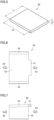
embodiment 1 of the present invention will be described with reference toFigs. 1 to 14 .Fig. 1 illustrates a plan view of anEC sensor 101 according to the present embodiment.Fig. 2 is a side view of theEC sensor 101.Fig. 3 is a bottom view of theEC sensor 101.Fig. 4 illustrates theEC sensor 101 as viewed in the direction ofarrow 91 inFig. 1 . TheEC sensor 101 includes anEC sensor body 81, anattachment 50, and arock wool piece 60. Therock wool piece 60 is fixed by theattachment 50.Fig. 5 is a perspective view of therock wool piece 60 removed separately. Therock wool piece 60 has a rectangular shape with a width of W, a length of L, and a thickness of t. -
Fig. 6 is a plan view of theattachment 50 only.Fig. 7 is a side view of theattachment 50 only.Fig. 8 illustrates theattachment 50 as viewed in the direction ofarrow 92 inFig. 6 .Fig. 9 illustrates theattachment 50 as viewed in the direction ofarrow 93 inFig. 6 .Fig. 10 is a bottom view of theattachment 50. -
Fig. 11 is a plan view of theEC sensor body 81 only.Fig. 12 is a side view of theEC sensor body 81 only. - The
EC sensor 101 includes ahousing 2 having a flatfirst surface 31, a plurality ofelectrodes 5 disposed to be exposed on thefirst surface 31, ameasurement circuit 3 that derives an EC value of a measurement object in accordance with an electrical resistance measured by applying a voltage between any two ormore electrodes 5 selected from the plurality ofelectrodes 5, theattachment 50 detachably attached to thehousing 2, and arock wool piece 60 fixed to thehousing 2 by being held by theattachment 50. Theattachment 50 includes aplate portion 53 andleg portions 54. Theplate portion 53 is spaced apart from thefirst surface 31 by a certain distance to face the plurality ofelectrodes 5 with theattachment 50 attached to thehousing 2. Theleg portions 54 fix the relative position of theplate portion 53 with respect to thehousing 2. Therock wool piece 60 includes a portion exposed to the outside of theattachment 50. - As illustrated in
Fig. 1 , theEC sensor body 81 includes thehousing 2 and acable 6. Thehousing 2 includes atip portion 21 and aroot portion 22. A side of thehousing 2 closer to thetip portion 21 is referred to as a front side, and a side closer to theroot portion 22 is referred to as a back side. Thecable 6 extends backward from theroot portion 22. However, thecable 6 may be absent. Themeasurement circuit 3 is accommodated in thehousing 2. Themeasurement circuit 3 is a board on which electronic components are mounted. The size and the shape of themeasurement circuit 3 indicated by a dashed line inFig. 1 and the like are merely schematic, and themeasurement circuit 3 may have another size and shape. In addition, themeasurement circuit 3 does not need to be built into thehousing 2 and may be disposed at another position. - The
housing 2 has asecond surface 32 in addition to thefirst surface 31. As illustrated inFig. 2 , thefirst surface 31 and thesecond surface 32 are flat. Thesecond surface 32 is located higher than thefirst surface 31. A temperature sensor may be provided on thefirst surface 31. Aslope 9 is provided between thefirst surface 31 and thesecond surface 32. As illustrated inFig. 11 , anelectrode portion 4 is provided on thefirst surface 31. Nineelectrodes 5 are disposed in theelectrode portion 4. The number ofelectrodes 5 is 9 here, but this is only an example. The number ofelectrodes 5 may be any number other than 9 that is equal to or more than 2. The top surface of theelectrode 5 has, for example, a circular shape with a diameter of 2 mm. The distance between theelectrodes 5 is, for example, 1 mm. Although theelectrodes 5 slightly project from thefirst surface 31 inFig. 12 , theelectrodes 5 may project from or do not need to project from thefirst surface 31. As illustrated inFigs. 1 and 2 , twocylindrical stoppers 7 are formed on theslope 9. As illustrated inFig. 3 , thehousing 2 has agroove 11 on a side opposite to thefirst surface 31. As illustrated inFig. 4 , the cross section of thegroove 11 has a substantially V-shape. TheEC sensor 101 may also have a pair of electrodes disposed along the inner surface of thegroove 11 in thehousing 2. A water sensor may be formed by using this pair of electrodes. - As illustrated in
Figs. 6 and 7 , theattachment 50 has acontact portion 51 that projects from theplate portion 53. InFigs. 6 and 7 , the left side is the front and the right side is the rear side. Thecontact portion 51 is disposed on the rear side of theattachment 50. As illustrated inFigs. 1 and 2 , thecontact portion 51 is in contact withstoppers 7. As illustrated inFigs. 8 and 9 ,claw portions 54a are provided at the ends of thefoot portions 54. Theclaw portions 54a project so as to face each other. As illustrated inFig. 4 , a step of thehousing 2 is hooked by theclaw portions 54a.Thick portions 55 are provided in joints between theplate portion 53 and theleg portions 54. - In
Fig. 5 , the width W of therock wool piece 60 may be, for example, 20 mm. The length L of therock wool piece 60 in the front-rear direction may be, for example, 20 mm or may also be 25 mm. The length L may be 25 mm and a 5 mm portion thereof may project from theplate portion 53 of theattachment 50. A front portion of therock wool piece 60 projects from theplate portion 53 in the present embodiment but does not need to project from theplate portion 53. -
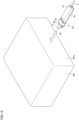
Fig. 13 illustrates an example of use of theEC sensor 101. Here, the measurement object is arock wool member 501. Therock wool member 501 has aside surface 501a. TheEC sensor 101 is inserted into theside surface 501a of therock wool member 501 with thetip portion 21 facing forward.Fig. 14 illustrates the state in which theEC sensor 101 has been inserted as described above. Therock wool piece 60 fixed to theEC sensor body 81 by theattachment 50 is in contact with therock wool member 501. - Since the
rock wool piece 60 includes a portion exposed to the outside of theattachment 50 in the present embodiment, therock wool piece 60 held by theattachment 50 can sufficiently come into contact with the measurement object. Accordingly, since the moisture contained in the artificial soil sufficiently penetrates therock wool piece 60 and measurement is performed by the plurality ofelectrodes 5 via therock wool piece 60 even when the measurement object is artificial soil, stable and accurate measurements can be performed even when the measurement object is artificial soil. - As illustrated in the present embodiment, the
rock wool piece 60 preferably includes a portion sandwiched between theplate portion 53 and thefirst surface 31 and a portion extending to the outside of the region covered with theplate portion 53. In this structure, since the portion extending to the outside can easily come into contact with surrounding artificial soil and the like with a sufficiently large area, more stable and accurate measurements can be performed. - As illustrated in the present embodiment, preferably, the
housing 2 includes thetip portion 21 and theroot portion 22, thefirst surface 31 is disposed to face a side orthogonal to a straight line connecting thetip portion 21 and theroot portion 22 to each other, and theattachment 50 is preferably detachable from thetip portion 21. In this structure, theattachment 50 can be easily attached and detached. In the present embodiment, thefirst surface 31 faces a side orthogonal to the straight line connecting thetip portion 21 and theroot portion 22 to each other, that is, faces the upper side inFig. 2 . - As illustrated in the present embodiment, the
leg portions 54 are preferably slidable with respect to thehousing 2 while holding thehousing 2 therebetween. In this structure, theattachment 50 can be smoothly attached and detached. - As illustrated in
Figs. 1 and 2 , thehousing 2 includes thestoppers 7 that project to come into contact with theattachment 50, and theattachment 50 is preferably suppressed from sliding toward theroot portion 22 from a certain position in thehousing 2 by thestoppers 7 in contact with theattachment 50. In this structure, the relative position of theattachment 50 with respect to thehousing 2 can be fixed at a proper position with great certainty. - It should be noted that the distance between a surface of the
plate portion 53 closest to thefirst surface 31 and thefirst surface 31, that is, the distance G inFig. 4 is preferably not less than 2.5 mm and not more than 3.0 mm. In this structure, theEC sensor 101 has an easy-to-handle size and can properly hold therock wool piece 60. - The thickness of the
rock wool piece 60 removed separately, that is, the thickness t inFig. 4 , is preferably not less than 2.5 mm and not more than 5.0 mm. The thickness t is the thickness of therock wool piece 60 before being deformed by compression. In this structure, measurements through therock wool piece 60 can be properly performed. InFig. 4 , a portion of therock wool piece 60 on the near side has the original thickness t. Since t > G in the example illustrated here, a portion of therock wool piece 60 on the far side has a thickness of G because the portion is compressed and deformed by being pressed by theplate portion 53 of theattachment 50. In this state, therock wool piece 60 is fixed to thehousing 2 of theEC sensor body 81. - The value obtained by dividing the thickness t of the
rock wool piece 60 removed separately by the distance G between a surface of theplate portion 53 closer to thefirst surface 31 and thefirst surface 31 is preferably not less than 5/6 and not more than 5/3. In this structure, therock wool piece 60 can be appropriately fixed by theattachment 50. - It should be noted that the structure of the
attachment 50 can be expressed as follows in accordance with the above description. - The
attachment 50 is detachably attached to thehousing 2 of anEC sensor 101 including the plurality ofelectrodes 5 disposed on the flatfirst surface 31 of thehousing 2 to derive the EC value of the measurement object and includes theplate portion 53 spaced apart from thefirst surface 31 by a certain distance to face the plurality ofelectrodes 5 with theattachment 50 attached to thehousing 2 and theleg portion 54 that fixes the relative position of theplate portion 53 with respect to thehousing 2. Theleg portions 54 are preferably slidable with respect to thehousing 2 while holding thehousing 2 therebetween. - The EC sensor described so far is suitable not only for use in artificial soil, such as rock wool or coconut peat, but also for use in mud in a rice paddy. In
Figs. 13 and14 , the case in which the measurement object is therock wool member 501 has been described, but when the measurement object is coconut peat, the EC sensor may be buried in coconut peat. When the measurement object is mud in a rice paddy, the EC sensor may be buried in mud in a rice paddy. When the measurement object is something other than a rock wool member, that is, also when the measurement object is coconut peat, another type of artificial soil, or natural soil, therock wool member 60 fixed by theattachment 50 does not need to be changed and the samerock wool member 60 may be used. - It should be noted that, when the EC sensor includes the
cable 6, thecable 6 may be disposed so as to be extracted from artificial soil, general soil, or mud. Some communication device, recording device, information processing device, or the like may be connected to the end of thecable 6. - It should be noted that some of the embodiments described above may be combined as appropriate.
- An EC sensor comprising:
- a housing having a flat first surface;
- a plurality of electrodes disposed to be exposed on the first surface;
- a measurement circuit that derives an EC value of a measurement object in accordance with an electrical resistance measured by applying a voltage between any two or more electrodes selected from the plurality of electrodes;
- an attachment detachably attached to the housing; and
- a rock wool piece fixed to the housing while being in contact with the plurality of electrodes by being held by the attachment,
- wherein the attachment includes a plate portion spaced apart from the first surface by a certain distance to face the plurality of electrodes with the attachment attached to the housing and a leg portion that fixes a relative position of the plate portion with respect to the housing, and
- the rock wool piece includes a portion exposed to an outside of the attachment.
- The EC sensor according to
Appendix 1,
wherein the rock wool piece includes a portion sandwiched between the plate portion and the first surface and a portion extending to an outside of a region covered with the plate portion. - The EC sensor according to
Appendix
wherein the housing includes a tip portion and a root portion, and the first surface is disposed to face a side orthogonal to a straight line connecting the tip portion and the root portion to each other, and the attachment is detachable from the tip portion. - The EC sensor according to
Appendix 3,
wherein the leg portion is slidable with respect to the housing while holding the housing. - The EC sensor according to
Appendix 4,
wherein the housing includes a stopper that projects to be into contact with the attachment, and the attachment is suppressed from sliding toward the root portion from a certain position in the housing by the stopper in contact with the attachment. - The EC sensor according to any one of
Appendixes 1 to 5,
wherein a distance between a surface of the plate portion closer to the first surface and the first surface is not less than 2.5 mm and not more than 3.0 mm. - The EC sensor according to any one of
Appendixes 1 to 6,
wherein a thickness of the rock wool piece removed separately is not less than 2.5 mm and not more than 5.0 mm. - The EC sensor according to any one of
Appendixes 1 to 7,
wherein a value obtained by dividing a thickness of the rock wool piece removed separately by a distance between a surface of the plate portion closer to the first surface and the first surface is not less than 5/6 and not more than 5/3. - An attachment detachably attached to a housing of an EC sensor including a plurality of electrodes disposed on a flat first surface of the housing to derive an EC value of a measurement object, the attachment comprising:
- a plate portion spaced apart from the first surface by a certain distance to face the plurality of electrodes with the attachment attached to the housing; and
- a leg portion that fixes a relative position of the plate portion with respect to the housing.
- The attachment according to
Appendix 9,
wherein the leg portion is slidable with respect to the housing while holding the housing. - It should be noted that the embodiment disclosed herein is merely illustrative and not restrictive in any way. The scope of the present invention is defined by the claims and includes the meaning equivalent to the claims and all modifications within the claims.
-
- 2 housing
- 3 measurement circuit
- 4 electrode portion
- 5 electrode
- 6 cable
- 7 stopper
- 9 slope
- 11 groove
- 21 tip portion
- 22 root portion
- 31 first surface
- 32 second surface
- 50 attachment
- 51 contact portion
- 53 plate portion
- 54 leg portion
- 54a claw portion
- 55 thick portion
- 60 rock wool piece
- 81 EC sensor body
- 91, 92, 93, 94 arrow
- 101 EC sensor
- 501 rock wool member
- 501a side surface
Claims (10)
- An EC sensor comprising:a housing having a flat first surface;a plurality of electrodes disposed to be exposed on the first surface;a measurement circuit that derives an EC value of a measurement object in accordance with an electrical resistance measured by applying a voltage between any two or more electrodes selected from the plurality of electrodes;an attachment detachably attached to the housing; anda rock wool piece fixed to the housing while being in contact with the plurality of electrodes by being held by the attachment,wherein the attachment includes a plate portion spaced apart from the first surface by a certain distance to face the plurality of electrodes with the attachment attached to the housing and a leg portion that fixes a relative position of the plate portion with respect to the housing, andthe rock wool piece includes a portion exposed to an outside of the attachment.
- The EC sensor according to Claim 1,
wherein the rock wool piece includes a portion sandwiched between the plate portion and the first surface and a portion extending to an outside of a region covered with the plate portion. - The EC sensor according to Claim 1 or 2,
wherein the housing includes a tip portion and a root portion, the first surface is disposed to face a side orthogonal to a straight line connecting the tip portion and the root portion to each other, and the attachment is detachable from the tip portion. - The EC sensor according to Claim 3,
wherein the leg portion is slidable with respect to the housing while holding the housing. - The EC sensor according to Claim 4,
wherein the housing includes a stopper that projects to be in contact with the attachment, and the attachment is suppressed from sliding toward the root portion from a certain position in the housing by the stopper in contact with the attachment. - The EC sensor according to any one of Claims 1 to 5,
wherein a distance between a surface of the plate portion closer to the first surface and the first surface is not less than 2.5 mm and not more than 3.0 mm. - The EC sensor according to any one of Claims 1 to 6,
wherein a thickness of the rock wool piece removed separately is not less than 2.5 mm and not more than 5.0 mm. - The EC sensor according to any one of Claims 1 to 7,
wherein a value obtained by dividing a thickness of the rock wool piece removed separately by a distance between a surface of the plate portion closer to the first surface and the first surface is not less than 5/6 and not more than 5/3. - An attachment detachably attached to a housing of an EC sensor including a plurality of electrodes disposed on a flat first surface of the housing to derive an EC value of a measurement object, the attachment comprising:a plate portion spaced apart from the first surface by a certain distance to face the plurality of electrodes with the attachment attached to the housing; anda leg portion that fixes a relative position of the plate portion with respect to the housing.
- The attachment according to Claim 9,
wherein the leg portion is slidable with respect to the housing while holding the housing.
Applications Claiming Priority (2)
| Application Number | Priority Date | Filing Date | Title |
|---|---|---|---|
| JP2022074914 | 2022-04-28 | ||
| PCT/JP2023/005437 WO2023210119A1 (en) | 2022-04-28 | 2023-02-16 | Ec sensor and attachment |
Publications (2)
| Publication Number | Publication Date |
|---|---|
| EP4517313A1 true EP4517313A1 (en) | 2025-03-05 |
| EP4517313A4 EP4517313A4 (en) | 2026-03-11 |
Family
ID=88518455
Family Applications (1)
| Application Number | Title | Priority Date | Filing Date |
|---|---|---|---|
| EP23795867.3A Pending EP4517313A4 (en) | 2022-04-28 | 2023-02-16 | EC sensor and mounting |
Country Status (3)
| Country | Link |
|---|---|
| EP (1) | EP4517313A4 (en) |
| CN (1) | CN118805081A (en) |
| WO (1) | WO2023210119A1 (en) |
Family Cites Families (10)
| Publication number | Priority date | Publication date | Assignee | Title |
|---|---|---|---|---|
| JPH0629869B2 (en) * | 1987-01-06 | 1994-04-20 | 日本碍子株式会社 | Electrical conductivity measurement terminal |
| JPH0833363B2 (en) * | 1987-08-26 | 1996-03-29 | 静岡県 | Detector for nutrient solution concentration in medium |
| GB2256926B (en) * | 1991-06-13 | 1995-02-08 | Liebermann Arax Ltd | Moisture meter |
| JP3303130B2 (en) * | 1998-10-09 | 2002-07-15 | 独立行政法人防災科学技術研究所 | Mixing amount measuring device and monitoring device for mixed substances |
| JP5834599B2 (en) * | 2011-08-01 | 2015-12-24 | オムロンヘルスケア株式会社 | Sensor head, electrochemical sensor, and method of using electrochemical sensor |
| JP2014169901A (en) * | 2013-03-01 | 2014-09-18 | Horiba Ltd | Method for measuring exchangeable potassium |
| WO2018110219A1 (en) | 2016-12-12 | 2018-06-21 | 株式会社村田製作所 | Ec sensor and field management system using same |
| EP3381250B1 (en) * | 2017-03-31 | 2020-06-03 | Scheppach Fabrikation von Holzbearbeitungsmaschinen GmbH | Gardening device for cultivating soil, and sowing or planting method with the aid of such gardening device |
| JP6996738B2 (en) * | 2017-10-27 | 2022-01-17 | ラピスセミコンダクタ株式会社 | measuring device |
| DE102019218812A1 (en) * | 2019-12-03 | 2021-06-10 | Fraunhofer-Gesellschaft zur Förderung der angewandten Forschung e.V. | Matrix potential sensor and measuring method for determining the matrix potential |
-
2023
- 2023-02-16 CN CN202380026395.XA patent/CN118805081A/en active Pending
- 2023-02-16 EP EP23795867.3A patent/EP4517313A4/en active Pending
- 2023-02-16 WO PCT/JP2023/005437 patent/WO2023210119A1/en not_active Ceased
Also Published As
| Publication number | Publication date |
|---|---|
| EP4517313A4 (en) | 2026-03-11 |
| CN118805081A (en) | 2024-10-18 |
| WO2023210119A1 (en) | 2023-11-02 |
Similar Documents
| Publication | Publication Date | Title |
|---|---|---|
| US20240277266A1 (en) | Sensor holder device for invasive biosensors | |
| TWI699189B (en) | Biological sensing device and method for starting biological sensing device | |
| US8577438B2 (en) | Sensor for in-vivo measurements | |
| US8643387B2 (en) | Moisture sensor | |
| US4204544A (en) | Simultaneous muscle force and displacement transducer | |
| CN102243047B (en) | Wire length measurement device | |
| US8601709B2 (en) | Measurement device for measuring length of an electrical wire between two connectors | |
| US20110309853A1 (en) | Sectional test probe assembly for electric meter | |
| WO2023210119A1 (en) | Ec sensor and attachment | |
| CN219516269U (en) | Electrode belt and electrode assembly for electrical impedance imaging | |
| US11213227B2 (en) | Pulse oximeter | |
| TW201142239A (en) | Length measuring device for wire | |
| JP2019082338A (en) | Measurement apparatus | |
| US12369829B2 (en) | Electric apparatus and its manufacturing method | |
| JP6241914B2 (en) | Sensor chip holder | |
| CN218938385U (en) | Horn antenna fixing bracket | |
| JP2014226165A (en) | Golf club and shaft flexure measurement system | |
| CN209280890U (en) | Internal resistance of cell test table | |
| CN210470063U (en) | Circuit board assembly structure convenient and stable to assemble | |
| CN206134959U (en) | Anemometry equipment ground connecting device and use its anemometry equipment | |
| CN114469067A (en) | Foot structure and stress characteristic measuring method and device | |
| JPS6310529Y2 (en) | ||
| TWM392352U (en) | Disassemble type measuring rod structure used in an electrical meter | |
| KR20170004148U (en) | center finder | |
| TWM332996U (en) | Electrical connector assembly |
Legal Events
| Date | Code | Title | Description |
|---|---|---|---|
| STAA | Information on the status of an ep patent application or granted ep patent |
Free format text: STATUS: THE INTERNATIONAL PUBLICATION HAS BEEN MADE |
|
| PUAI | Public reference made under article 153(3) epc to a published international application that has entered the european phase |
Free format text: ORIGINAL CODE: 0009012 |
|
| STAA | Information on the status of an ep patent application or granted ep patent |
Free format text: STATUS: REQUEST FOR EXAMINATION WAS MADE |
|
| 17P | Request for examination filed |
Effective date: 20240808 |
|
| AK | Designated contracting states |
Kind code of ref document: A1 Designated state(s): AL AT BE BG CH CY CZ DE DK EE ES FI FR GB GR HR HU IE IS IT LI LT LU LV MC ME MK MT NL NO PL PT RO RS SE SI SK SM TR |
|
| DAV | Request for validation of the european patent (deleted) | ||
| DAX | Request for extension of the european patent (deleted) | ||
| A4 | Supplementary search report drawn up and despatched |
Effective date: 20260211 |
|
| RIC1 | Information provided on ipc code assigned before grant |
Ipc: G01N 27/04 20060101AFI20260205BHEP Ipc: G01N 33/24 20060101ALI20260205BHEP Ipc: G01R 27/02 20060101ALI20260205BHEP Ipc: G01N 27/12 20060101ALI20260205BHEP |