EP4517294A1 - Method and device for obtaining forming limit of metal sheet - Google Patents
Method and device for obtaining forming limit of metal sheet Download PDFInfo
- Publication number
- EP4517294A1 EP4517294A1 EP23835107.6A EP23835107A EP4517294A1 EP 4517294 A1 EP4517294 A1 EP 4517294A1 EP 23835107 A EP23835107 A EP 23835107A EP 4517294 A1 EP4517294 A1 EP 4517294A1
- Authority
- EP
- European Patent Office
- Prior art keywords
- forming limit
- strain
- forming
- test piece
- bending deformation
- Prior art date
- Legal status (The legal status is an assumption and is not a legal conclusion. Google has not performed a legal analysis and makes no representation as to the accuracy of the status listed.)
- Pending
Links
Images



Classifications
-
- G—PHYSICS
- G01—MEASURING; TESTING
- G01N—INVESTIGATING OR ANALYSING MATERIALS BY DETERMINING THEIR CHEMICAL OR PHYSICAL PROPERTIES
- G01N3/00—Investigating strength properties of solid materials by application of mechanical stress
- G01N3/28—Investigating ductility, e.g. suitability of sheet metal for deep-drawing or spinning
-
- B—PERFORMING OPERATIONS; TRANSPORTING
- B21—MECHANICAL METAL-WORKING WITHOUT ESSENTIALLY REMOVING MATERIAL; PUNCHING METAL
- B21D—WORKING OR PROCESSING OF SHEET METAL OR METAL TUBES, RODS OR PROFILES WITHOUT ESSENTIALLY REMOVING MATERIAL; PUNCHING METAL
- B21D22/00—Shaping without cutting, by stamping, spinning, or deep-drawing
-
- G—PHYSICS
- G01—MEASURING; TESTING
- G01N—INVESTIGATING OR ANALYSING MATERIALS BY DETERMINING THEIR CHEMICAL OR PHYSICAL PROPERTIES
- G01N3/00—Investigating strength properties of solid materials by application of mechanical stress
- G01N3/02—Details
- G01N3/06—Special adaptations of indicating or recording means
- G01N3/068—Special adaptations of indicating or recording means with optical indicating or recording means
-
- G—PHYSICS
- G01—MEASURING; TESTING
- G01N—INVESTIGATING OR ANALYSING MATERIALS BY DETERMINING THEIR CHEMICAL OR PHYSICAL PROPERTIES
- G01N3/00—Investigating strength properties of solid materials by application of mechanical stress
- G01N3/20—Investigating strength properties of solid materials by application of mechanical stress by applying steady bending forces
-
- G—PHYSICS
- G01—MEASURING; TESTING
- G01N—INVESTIGATING OR ANALYSING MATERIALS BY DETERMINING THEIR CHEMICAL OR PHYSICAL PROPERTIES
- G01N2203/00—Investigating strength properties of solid materials by application of mechanical stress
- G01N2203/0014—Type of force applied
- G01N2203/0023—Bending
-
- G—PHYSICS
- G01—MEASURING; TESTING
- G01N—INVESTIGATING OR ANALYSING MATERIALS BY DETERMINING THEIR CHEMICAL OR PHYSICAL PROPERTIES
- G01N2203/00—Investigating strength properties of solid materials by application of mechanical stress
- G01N2203/0058—Kind of property studied
- G01N2203/006—Crack, flaws, fracture or rupture
-
- G—PHYSICS
- G01—MEASURING; TESTING
- G01N—INVESTIGATING OR ANALYSING MATERIALS BY DETERMINING THEIR CHEMICAL OR PHYSICAL PROPERTIES
- G01N2203/00—Investigating strength properties of solid materials by application of mechanical stress
- G01N2203/0058—Kind of property studied
- G01N2203/0069—Fatigue, creep, strain-stress relations or elastic constants
- G01N2203/0075—Strain-stress relations or elastic constants
-
- G—PHYSICS
- G01—MEASURING; TESTING
- G01N—INVESTIGATING OR ANALYSING MATERIALS BY DETERMINING THEIR CHEMICAL OR PHYSICAL PROPERTIES
- G01N2203/00—Investigating strength properties of solid materials by application of mechanical stress
- G01N2203/02—Details not specific for a particular testing method
- G01N2203/0202—Control of the test
- G01N2203/0212—Theories, calculations
- G01N2203/0218—Calculations based on experimental data
-
- G—PHYSICS
- G01—MEASURING; TESTING
- G01N—INVESTIGATING OR ANALYSING MATERIALS BY DETERMINING THEIR CHEMICAL OR PHYSICAL PROPERTIES
- G01N2203/00—Investigating strength properties of solid materials by application of mechanical stress
- G01N2203/02—Details not specific for a particular testing method
- G01N2203/026—Specifications of the specimen
- G01N2203/0298—Manufacturing or preparing specimens
-
- G—PHYSICS
- G01—MEASURING; TESTING
- G01N—INVESTIGATING OR ANALYSING MATERIALS BY DETERMINING THEIR CHEMICAL OR PHYSICAL PROPERTIES
- G01N2203/00—Investigating strength properties of solid materials by application of mechanical stress
- G01N2203/02—Details not specific for a particular testing method
- G01N2203/06—Indicating or recording means; Sensing means
- G01N2203/0641—Indicating or recording means; Sensing means using optical, X-ray, ultraviolet, infrared or similar detectors
- G01N2203/0647—Image analysis
Definitions
- the present invention relates to a metal sheet forming limit acquisition method and apparatus to acquire a forming limit of a metal sheet in consideration of a bending deformation degree of the metal sheet.
- a metal sheet used as a material of an automotive body is mostly processed into an automotive part by press forming.
- Press formability of the automotive part varies depending on a shape of the automotive part, and is also greatly affected by a material property including ductility of a metal sheet such as a steel sheet that is a material.
- strength enhancement of a metal sheet such as a steel sheet used for an automotive part is in progress.
- ductility decreases along with the strength enhancement of the metal sheet, a fracture is likely to be generated in press forming, and press formability is deteriorated.
- a forming limit diagram (hereinafter, referred to as "FLD") is usually used to determine the forming limit of the metal sheet.
- the FLD is created by measurement of a forming limit in each of deformation forms (equibiaxial deformation, non-equibiaxial deformation, plane strain deformation, and uniaxial deformation) in press forming by a forming test on a laboratory scale. Then, in the creation of the forming limit diagram, a deformation ratio in a major axis direction and a minor axis direction of a test piece is changed by changing of a width of the test piece to some levels and a strain in each of the major axis direction and the minor axis direction at the time of generation of a fracture of the test piece is measured.
- a process in which the metal sheet is uniformly deformed transitions to a process in which strain concentrates on a specific place.
- a sheet thickness reduction called necking is generated at a portion where the strain of the metal sheet is concentrated, and the fracture is generated after the sheet thickness reduction proceeds. Since generation of necking causes a product defect in the press forming, it is necessary to define an amount of the strain immediately before the generation of necking in an FLD used for prior prediction of the product defect in a press formed part. Furthermore, in a high-strength steel sheet having a tensile strength exceeding 980 MPa, necking is generated at a low strain amount of about 10%, and the fracture is generated immediately thereafter. Thus, a method of accurately determining a forming limit has been proposed.
- a method of acquiring a forming limit curve (hereinafter, referred to as "FLC") of a metal sheet is standardized in ISO12004 (see Non-Patent Literature 1).
- FLC forming limit curve
- Non-Patent Literature 2 proposes, as a method of improving ISO12004, a method of continuously measuring a strain generated in a test piece during forming, and acquiring an FLC from a temporal change in a strain of a fracture generated portion.
- Patent Literature 1 proposes a method of performing bulge forming with a punch that has a minimum curvature radius of 3 to 10 mm at a tip, measuring a maximum principal strain and a minimum principal strain at the time when a crack is generated on a surface of a metal sheet at a tip portion of the punch, and creating a forming limit diagram.
- Patent Literature 1 Japanese Patent Application Laid-open No. 2012-166252
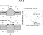
- the Nakajima test is a method of acquiring a forming limit by a bulge test in which bulge forming of a test piece 100 is performed with a molding die 41 including a hemispherical punch 43, an upper die 45, and a blank holder 47.
- a molding die 51 including a flat punch 53, an upper die 55, and a blank holder 57 is used.
- a forming limit is acquired by a bulge test in which bulge forming of a test piece 100 is performed with a driver sheet 110 being interposed between the flat punch 53 and the test piece 100.
- bulge forming is performed in a state in which the test piece 100 is fitted to a shape of a tip portion 43a of the hemispherical punch 43.
- the acquired forming limits maximum principal strain and minimum principal strain at the time of a fracture
- the bulge forming is performed with the flat punch 53 having a tip portion 53a with a flat surface.
- the strain amount immediately before the generation of necking is larger in the FLD acquired by the Nakajima test by about 1 to 2% as illustrated in FIG. 9(c) .
- a slight difference in the strain amount may cause a difference in constriction (necking) generation.
- the forming limit has been evaluated by comparison between the FLD of the Nakajima test and that of the Marciniak test from a strain amount measured in an actual press formed part and a strain amount acquired from a press forming analysis result using CAE.
- Non-Patent Literature 2 can accurately acquire the forming limit as compared with ISO12004.
- the forming limit cannot be acquired in consideration of a degree of a bending deformation.
- a result of prediction of presence or absence of fracture generation based on the forming limit diagram acquired by the method proposed in Non-Patent Literature 2 does not coincide with presence or absence of fracture generation in an actual press formed part in some cases.
- the forming limit curve created by the method of Patent Literature 1 is specialized for a case where a crack is generated from a surface of a steel sheet and a fracture is generated without generation of constriction (necking) as tensile strength of the steel sheet is enhanced and hardened to 980 MPa-class or 1180 MPa-class.
- the forming limit strain becomes higher than that in the Nakajima test, and it is not possible to predict generation of ductility-dominated fracture in which sheet thickness reduction progresses from the generation of localized constriction (localized necking) and the fracture is generated in actual press forming.
- a portion subjected to the bending deformation and a portion not subjected thereto are mixed, and a degree of the bending deformation varies depending on the portion.
- the degree of the bending deformation is not taken into consideration in the conventional method of acquiring the FLD.
- the present invention has been made in view of the above problems, and an object thereof is to provide a metal sheet forming limit acquisition method and apparatus capable of acquiring a forming limit of a metal sheet in consideration of an influence of bending deformation.
- a difference between the FLDs of the Nakajima test and the Marciniak test is as small as about 1 to 2% in terms of strain
- a slight difference in the strain (forming amount) causes a difference in generation of a fracture in a high-tensile steel sheet having low ductility.
- the inventors focused on presence or absence of bending deformation of a test piece in a forming limit test as one of causes of the difference between forming limits of the Nakajima test and the Marciniak test.
- FIG. 10 A relationship between the curvature of the tip portion 43a of the hemispherical punch 43 and the maximum principal strain representing the forming limit is illustrated in FIG. 10 .
- the maximum principal strain at the curvature 0 was acquired by the bulge test using the flat punch 53 illustrated in FIG. 9(b) .
- the maximum principal strain to be the forming limit becomes larger as the curvature of the tip portion 43a becomes larger, that is, in the bulge forming in which steep bending deformation is applied by the tip portion 43a of the hemispherical punch 43.
- the present invention has been made on the basis of such findings, and specifically has the following configurations.
- a metal sheet forming limit acquisition method includes: bulge forming a test piece of a metal sheet at various bending deformation degrees by using a plurality of hemispherical punches having different curvatures at tip portions; and acquiring a forming limit of the metal sheet which limit is represented by a relationship between a bending deformation degree of the bulge-formed test piece and a maximum principal strain and a minimum principal strain of the test piece bulge-formed at the bending deformation degrees.
- the bending deformation degrees may be expressed by the curvatures of the tip portions of the hemispherical punches.
- a metal sheet forming limit acquisition method is the method of acquiring a forming limit of a metal sheet in consideration of a bending deformation degree.
- the method includes: a forming test step; a forming limit analysis step; and a boundary surface of a forming limit creation step, wherein the forming test step includes a test piece preparation process of preparing a test piece in which a predetermined grid or strain analysis pattern is applied to a surface of the metal sheet, a bulge forming process of performing bulge forming of the test piece at various bending deformation degrees by using a plurality of hemispherical punches having different curvatures at tip portions while photographing a surface of the test piece provided with the grid or strain analysis pattern, a strain measurement process of analyzing an image of the surface of the test piece photographed in the bulge forming process and measuring a strain generated in the test piece for each of the bending deformation degrees of the bulge-formed test piece, and a strain database construction process of storing the strain measured for each
- a polygonal surface including a plurality of triangular planes each of which connects two adjacent plots among plots of a forming limit strain group having a same bending deformation degree and one plot that has a shortest distance to a line segment connecting the two plots and that is among plots of a forming limit strain group having a bending deformation degree different from that of the two plots may be created.
- a boundary flat surface of a forming limit or a boundary curved surface of a forming limit may be assumed, a sum of squares of a vertical distance between the assumed boundary flat surface of a forming limit or boundary curved surface of a forming limit and a plot of the forming limit strain for each of the bending deformation degrees in the three-dimensional coordinate space may be acquired, and the boundary surface of a forming limit may be created by determination of the boundary flat surface of a forming limit or the boundary curved surface of a forming limit at which the acquired sum of squares is minimized.
- a boundary flat surface of a forming limit or a boundary curved surface of a forming limit may be assumed, a sum of squares in which a vertical distance between the assumed boundary flat surface of a forming limit or boundary curved surface of a forming limit and a plot of the forming limit strain for each of the bending deformation degrees in the three-dimensional coordinate space is weighted may be acquired, and the boundary surface of a forming limit may be created by determination of the boundary flat surface of a forming limit or the boundary curved surface of a forming limit in such a manner that the acquired sum of squares is minimized.
- the boundary surface of a forming limit may be created by combination of a plurality of the boundary flat surfaces of a forming limit and boundary curved surfaces of a forming limit.
- a metal sheet forming limit acquisition apparatus is the apparatus of acquiring a forming limit of a metal sheet in consideration of a bending deformation degree.
- the apparatus includes: a forming test unit; a forming limit analysis unit; and a boundary surface of a forming limit creation unit, wherein the forming test unit includes a molding die that includes a plurality of hemispherical punches having different curvatures at tip portions, and performs bulge forming of a test piece of the metal sheet, to which a predetermined grid or strain analysis pattern is applied, at various bending deformation degrees by using the plurality of hemispherical punches, a photographing device that photographs a surface of the test piece in a process of bulge forming the test piece with the molding die, a strain measurement device that analyzes an image of the surface of the test piece photographed by the photographing device and measures a strain generated in the test piece for each of the bending deformation degrees, and a strain database construction device that constructs a strain
- the test piece of the metal sheet is subjected to the bulge forming at various bending deformation degrees, and the bending deformation degree is acquired in addition to the maximum principal strain and the minimum principal strain as indexes of the forming limit, whereby the forming limit of the metal sheet can be acquired in consideration of the influence of the bending deformation. Furthermore, according to the present invention, it is possible to acquire a boundary surface of a forming limit which surface is represented by a relationship among the bending deformation degree, the maximum principal strain, and the minimum principal strain.
- the metal sheet forming limit acquisition method (hereinafter, also simply referred to as "forming limit acquisition method") according to the present embodiment is to perform bulge forming of a test piece 100 of the metal sheet at various bending deformation degrees by using a plurality of hemispherical punches 11a having different curvatures at tip portions 11a1. Then, the forming limit acquisition method is to acquire a forming limit of the metal sheet which limit is represented by a relationship between a bending deformation degree of the bulge-formed test piece and a maximum principal strain and a minimum principal strain at a fracture generated portion of the test piece bulge-formed at the bending deformation degree.
- each of the hemispherical punches 11a according to the present invention has the tip portion 11a1 having the curvature ⁇ of 0 or more.
- test piece 100 As the test piece 100, a test piece 101 and a test piece 103 having shapes illustrated as examples in FIG. 3 are used to acquire a forming limit in each of the deformation forms (equibiaxial deformation, non-equibiaxial deformation, plane strain deformation, and uniaxial deformation) in press forming.
- the test piece 101 As illustrated in FIG. 3(a) , the test piece 101 has a disk shape, and is to acquire a forming limit of the equibiaxial deformation.
- a cut-out portion 103a having a shape cut out in an arc shape is formed at a position facing a diameter direction of a disk-shaped peripheral edge portion.
- a width W of a narrowest portion in a central portion 103b is variously changed.
- the equibiaxial deformation is changed to the non-equibiaxial deformation and the plane strain deformation, and is gradually brought close to uniaxial tension, and the forming limit in each of the deformation forms is acquired.
- the test piece 100 is assumed to have a predetermined grid or strain analysis pattern on a surface of the metal sheet.
- the bending deformation degree serving as an index of the forming limit represents a degree of the bending deformation in the bulge-formed portion in the test piece 100, and a measured value of a curvature radius or a curvature of the bulge-formed portion can be used as the bending deformation degree.
- the bending deformation degree may be expressed by the curvature of the tip portion 11a1 of the hemispherical punch 11a used for the bulge forming of the test piece 100 without actual measurement of the curvature radius or the curvature of the bulge-formed portion.
- the method of acquiring the maximum principal strain and the minimum principal strain to be indices of the forming limit is not specifically limited. It is only necessary that the forming limit is acquired on the same basis for the strain measured by utilization of the plurality of hemispherical punches 11a having the different curvatures at the tip portions 11a1.
- the maximum principal strain and the minimum principal strain at the time of generation of a fracture may be acquired from a shape of marking applied to the surface of the test piece 100 in a vicinity of a fracture generated portion of the test piece 100 bulge-formed until the fracture is generated, or may be acquired by a method described later.
- a specific aspect of the forming limit acquisition method according to the present embodiment will be described.
- a specific aspect of the forming limit acquisition method according to the present embodiment as illustrated in FIG. 1 , what includes a forming test step S10, a forming limit analysis step S20, and a boundary surface of a forming limit creation step S30 can be described as an example.
- the forming test step S10 includes a test piece preparation process S11, a bulge forming process S13, a strain measurement process S15, and a strain database construction process S17.
- the test piece preparation process S11 is a process of preparing the test piece 100 in which a predetermined grid or strain analysis pattern is applied to the surface of the metal sheet.
- the circular test piece 101 and the test piece 103 having the shape in which the cut-out portion 103a is formed in a circular outer edge portion are prepared.
- test pieces in which the width W of the central portion 103b is changed at a plurality of levels are prepared.
- the bulge forming process S13 is a process of performing bulge forming of the test piece 100 at various bending deformation degrees by using the plurality of hemispherical punches 11a having different curvatures at the tip portions 11a1 while photographing the surface of the test piece 100 to which surface the grid or strain analysis pattern is applied.
- the strain measurement process S15 is a process of analyzing an image of the surface of the test piece 100 photographed in the bulge forming process S13 and measuring the strain generated in the test piece 100 for each of the bending deformation degrees.
- a method of measuring the strain for example, digital image correlation (hereinafter, referred to as "DIC" is used.
- the surface of the test piece 100 in the bulge forming process is imaged at predetermined time intervals, an image analysis of an image imaged in each time step is performed, and the maximum principal strain and the minimum principal strain are measured as strain generated in the test piece 100 in two in-plane directions according to the deformation degree of the grid or strain analysis pattern.
- the forming limit analysis step S20 includes a strain distribution extraction process S21 and a forming limit acquisition process S23.
- the strain distribution extraction process S21 is a process of extracting strain distribution in the vicinity of the fracture generated portion of the test piece 100 bulge-formed at various bending deformation degrees from the strain database constructed in the strain database construction process S17.
- the strain distribution extracted in the strain distribution extraction process S21 is time-series data of the strain stored for each of the bending deformation degrees in the strain database.
- the forming limit strain may be acquired, for example, as follows. First, in the strain distribution extraction process S21, the maximum principal strain and the minimum principal strain in the vicinity of the fracture generated portion of the test piece 100 are extracted for each predetermined time step from the start of forming to the fracture for each of the bending deformation degrees, and the time-series data is created.
- the forming limit strain may be acquired by any method as long as the strain measured in the bulge test using the plurality of hemispherical punches 11a having the different curvatures at the tip portion 11a1 is acquired on the basis of the same criterion.
- the forming limit plotting process S31 is a process of plotting the forming limit strain, which is acquired for each of the bending deformation degrees in the forming limit analysis step S20, in a three-dimensional coordinate space having three axes of the maximum principal strain, the minimum principal strain, and the bending deformation degree.
- the boundary surface of a forming limit creation process S33 is a process of creating a boundary surface of a forming limit on the basis of the forming limit plotted in the three-dimensional coordinate space having the maximum principal strain, the minimum principal strain, and the bending deformation degree as coordinate axes in the forming limit plotting process S31.
- the boundary surface of a forming limit which surface is created in the boundary surface of a forming limit creation process S33 is represented by the relationship among the maximum principal strain, the minimum principal strain, and the bending deformation degree.
- first method first, plots of two forming limit strains with equal bending deformation degrees are extracted. Then, in a forming limit strain group of a bending deformation degree different from that of the two forming limit strains, a plot of one forming limit strain having the shortest distance to a line segment connecting the plots of the two forming limit strains is selected. Subsequently, a triangular plane is formed by the two extracted forming limit strain plots and the one selected forming limit strain plot. Such a triangular plane is created for plots of all the forming strain groups. Then, a polygonal surface acquired by combination of the created triangular planes is set as the boundary surface of a forming limit.
- a boundary flat surface of a forming limit or a boundary curved surface of a forming limit is assumed in a three-dimensional coordinate space, and a vertical distance between the assumed boundary flat surface of a forming limit or boundary curved surface of a forming limit and a plot of the forming limit strain is calculated. Then, the boundary flat surface of a forming limit or the boundary curved surface of a forming limit is determined in such a manner that the sum of squares of the calculated vertical distance is minimized.
- a third method is a method of determining, in the second method, the boundary flat surface of a forming limit or the boundary curved surface of forming limit in such a manner that the sum of squares in which the vertical distance between the assumed boundary flat surface of a forming limit or boundary curved surface of a forming limit and the plot of the forming limit strain is weighted is minimized.
- weighting for example, it is preferable to increase the weight for the forming limit of the bending deformation degree at which the fracture is likely to be generated in actual press forming. As a result, it is possible to reduce an error between the determined boundary flat surface of a forming limit or boundary curved surface of a forming limit and the plot of the forming limit strain at the bending deformation degree at which the fracture is likely to be generated in the actual press forming.
- a plurality of the boundary flat surfaces of a forming limit and/or boundary curved surfaces of a forming limit may be combined.
- the boundary flat surface of a forming limit or the boundary curved surface of a forming limit is assumed in each of a negative region and a positive region of the minimum principal strain, and the boundary flat surface of a forming limit or the boundary curved surface of a forming limit may be determined in such a manner that the sum of squares of the vertical distance to the plot of the forming limit strain is minimized for each of the regions.
- the boundary surface of a forming limit is created in such a manner that the sum of squares in which the vertical distance to the plot of the forming limit strain is weighted is minimized.
- three adjacent points may be selected in the plot of the forming limit strain in the three-dimensional coordinate space
- a triangular plane may be generated by connection of the selected three points with straight lines
- a polygonal surface including a plurality of the triangular planes generated in such a manner may be used as the boundary surface of a forming limit.
- a forming limit curve may be created on the basis of the forming limit strain for each of the bending deformation degrees, and the boundary surface of a forming limit which surface includes the created forming limit curve may be created.
- the present invention can also be configured as an apparatus that creates a boundary surface of a forming limit of a metal sheet. That is, the metal sheet forming limit acquisition apparatus (hereinafter, simply referred to as "forming limit acquisition apparatus") according to the present embodiment is to acquire a forming limit of a metal sheet in consideration of a bending deformation degree.
- the forming limit acquisition apparatus 1 includes a forming test unit 10, a forming limit analysis unit 20, and a boundary surface of a forming limit creation unit 30.
- the forming test unit 10 includes a molding die 11, a photographing device 13, a strain measurement device 15, and a strain database construction device 17.
- the molding die 11 performs bulge forming of a test piece at various bending deformation degrees, and includes a plurality of hemispherical punches 11a having different curvatures at tip portions 11a1, an upper die 11b, and a blank holder 11c as illustrated in FIG. 2 .
- the photographing device 13 photographs a degree of deformation of the grid or the strain analysis pattern on the surface of the test piece 100 in the process of bulge forming the test piece 100, to which the grid or the strain analysis pattern is applied, with the molding die 11.
- the photographing device 13 includes, for example, two cameras, and performs stereo photographing of the surface of the test piece 100.
- the strain measurement device 15 analyzes an image of the surface of the test piece 100 photographed by the photographing device 13, and measures a strain generated in the test piece 100 for each of the bending deformation degrees of the bulge-formed test piece 100. For example, the strain measurement device 15 uses the digital image correlation and measures the maximum principal strain and the minimum principal strain as strains generated in the test piece 100 in two in-plane directions in the bulge forming process.
- the strain database construction device 17 constructs a strain database in which the strain measured by the strain measurement device 15 can be stored and extracted in time series from the start of forming to the fracture for each of bending deformation degrees of the bulge-formed test piece.
- the forming limit analysis unit 20 includes a strain distribution extraction device 21 and a forming limit acquisition device 23.
- the strain distribution extraction device 21 extracts a strain distribution in the vicinity of the fracture generated portion of the test piece 100 from the strain database constructed by the strain database construction device 17 for each of the bending deformation degrees of the bulge-formed test piece 100.
- the forming limit acquisition device 23 acquires a forming limit strain represented by the maximum principal strain and the minimum principal strain at the fracture generated portion of the test piece 100 for each of the bending deformation degrees of the test piece 100 from the strain distribution extracted by the strain distribution extraction device 21.
- the boundary surface of a forming limit creation unit 30 includes a forming limit plotting device 31 and a boundary surface of a forming limit creation device 33.
- the forming limit plotting device 31 plots a forming limit represented by a relationship between the bending deformation degree acquired by the forming limit analysis unit 20 and the maximum principal strain and the minimum principal strain in a three-dimensional coordinate space having three axes of the maximum principal strain, the minimum principal strain, and the bending deformation degree.
- the boundary surface of a forming limit creation device creates a boundary surface of a forming limit which surface is represented by a relationship among the maximum principal strain, the minimum principal strain, and the bending deformation degree on the basis of a forming limit plotted in a three-dimensional coordinate space by the forming limit plotting device 31.
- the test piece of the metal sheet is bulge-formed at various bending deformation degrees, and the maximum principal strain and the minimum principal strain of the fracture generated portion are acquired for each of the bending deformation degrees, whereby the forming limit in which an influence of the bending deformation is considered can be acquired.
- a forming limit strain group acquired from the test piece 100 formed by bulge forming using the specific hemispherical punch 43 or the flat punch 53, and one forming limit curve (FLC) that is an approximate line thereof are created.
- the bending deformation degree is expressed by the curvature at the tip portion of the hemispherical punch, and the bulge test is performed by utilization of a plurality of the hemispherical punches 11a having different curvatures at the tip portions.
- a forming limit strain group is acquired for each of the bending deformation degrees by the number of shapes of the hemispherical punches 11a.
- the forming limit can be plotted in the three-dimensional coordinate space having the maximum principal strain, the minimum principal strain, and the bending deformation degree as coordinate axes.
- the boundary surface of a forming limit which surface is represented by the relationship with the bending deformation degree in addition to the maximum principal strain and the minimum principal strain can be acquired.
- the maximum principal strain, the minimum principal strain, and a curvature in a direction of the maximum principal strain are acquired as the bending deformation degree by a press forming analysis of the press formed part.
- the present example was performed on the basis of a procedure illustrated in FIG. 5 .
- the test piece 100 was bulge-formed by utilization of the molding die 11 including the hemispherical punch 11a, the upper die 11b, and the blank holder 11c illustrated in FIG. 2 .
- a shape (curvature) of the tip portion 11a1 of the hemispherical punch 11a was determined.
- the curvatures at the tip portions 11a1 are 0.04, 0.02, 0.01, and 0.00, respectively.
- a test piece 100 of a high-strength steel sheet having a tensile strength of 1470 MPa-class and a sheet thickness of 1.4 mm was used as a test material of a metal sheet, and a shape of the test piece 100 was determined.
- shapes of the test piece 100 are a circular test piece 101 having a diameter of ⁇ 180 mm and a test piece 103 having a shape cut out in a width direction with the test piece 101 as a basis.
- the test piece 103 had five types of shapes in which a width W of a central portion 103b was from 25 mm to 160 mm.
- a test piece 103 having the width W of 60 mm is illustrated in FIG.
- FIG. 3(c) a test piece 103 having the width W of 80 mm is illustrated in FIG. 3(c) .
- a grid-like pattern (grid) for strain measurement was transferred to a surface of the test piece 100 having the shape determined in such a manner.
- the molding die 11 illustrated in FIG. 2 was set in a hydraulic-type deep drawing tester, and the test piece 100 was bulge-formed.
- a blank holder pressure of 50 ton was applied as a load by the blank holder, and a punch speed of the hemispherical punch 11a was set to 5 mm/min.
- the surface of the test piece 100 was photographed with an image analysis camera that is a photographing device (not illustrated) installed in an upper portion of the molding die 11.
- the photographed image of the surface of the test piece 100 was analyzed, and an amount of the strain (maximum principal strain and minimum principal strain) generated on the surface of the test piece 100 was measured.
- the measured strain amount was stored in the strain database.
- the surface of the test piece was photographed at an interval of once/second from the start of forming to generation of the fracture, the strain amount was measured for each of the photographed images, and the measurement was continued until it was determined that the fracture was generated.
- the forming limit analysis was performed in the forming limit analysis step S20 by utilization of the strain database constructed in the forming test step S10.
- evaluation points for acquiring the forming limit strain were set in the vicinity of the fracture generated portion of the test piece 100. Then, time-series data of the maximum principal strain and the minimum principal strain was extracted from the strain database for each of the set evaluation points.
- the maximum principal strain and the minimum principal strain at the bend point at which a uniform deformation changes to an inhomogeneous deformation were acquired as the forming limit strain. Furthermore, this operation was performed for all the hemispherical punches 11a that have different curvature radii at the tip portions 11a1 and that are used in the bulge test, and the forming limit strain (maximum principal strain and minimum principal strain) was acquired for each of the bending deformation degrees.
- Table 1 Values of the forming limit strain acquired for each of the bending deformation degrees are illustrated in Table 1. Furthermore, a graph in which the forming limit strain is plotted on a two-dimensional coordinate plane having the minimum principal strain and the maximum principal strain as coordinate axes is illustrated in FIG. 7 .
- a boundary surface of a forming limit was created on the basis of the forming limit strain acquired for each of the bending deformation degrees in the boundary surface of a forming limit creation step S30.
- the forming limit strain (forming limit data) acquired for each of the bending deformation degrees in the forming limit analysis step was extracted, and plotted in a three-dimensional coordinate space having the maximum principal strain, the minimum principal strain, and the bending deformation degree as coordinate axes.
- coefficients in the expression (1) were determined for each of the boundary flat surface of a forming limit A in the positive region and a boundary flat surface of a forming limit B in the negative region in such a manner that the sum of squares of a vertical distance between the assumed boundary surface of a forming limit and a plot of the forming limit strain group of each of the bending deformation degrees was minimized.
- the boundary flat surface of a forming limit A and the boundary flat surface of a forming limit B for which the coefficients in the expression (1) were determined and acquired as the boundary surfaces of a forming limit.
- the boundary surface of a forming limit which surface is represented by the relationship among the bending deformation degree, the maximum principal strain, and the minimum principal strain could be acquired.
- a metal sheet forming limit acquisition method and apparatus capable of determining a forming limit of a metal sheet in consideration of an influence of bending deformation.
Landscapes
- Physics & Mathematics (AREA)
- Health & Medical Sciences (AREA)
- Life Sciences & Earth Sciences (AREA)
- Chemical & Material Sciences (AREA)
- Analytical Chemistry (AREA)
- Biochemistry (AREA)
- General Health & Medical Sciences (AREA)
- General Physics & Mathematics (AREA)
- Immunology (AREA)
- Pathology (AREA)
- Engineering & Computer Science (AREA)
- Mechanical Engineering (AREA)
- Shaping Metal By Deep-Drawing, Or The Like (AREA)
- Investigating Strength Of Materials By Application Of Mechanical Stress (AREA)
- Bending Of Plates, Rods, And Pipes (AREA)
Abstract
Description
- The present invention relates to a metal sheet forming limit acquisition method and apparatus to acquire a forming limit of a metal sheet in consideration of a bending deformation degree of the metal sheet.
- A metal sheet used as a material of an automotive body is mostly processed into an automotive part by press forming. Press formability of the automotive part varies depending on a shape of the automotive part, and is also greatly affected by a material property including ductility of a metal sheet such as a steel sheet that is a material. In addition, in response to a demand for weight reduction of an automotive body in recent years, strength enhancement of a metal sheet such as a steel sheet used for an automotive part is in progress. However, as the ductility decreases along with the strength enhancement of the metal sheet, a fracture is likely to be generated in press forming, and press formability is deteriorated.
- Thus, in order to avoid a trouble such as generation of the fracture during mass production of the automotive part by press forming, die design based on prior prediction of press formability by computer aided engineering (CAE) is important. Furthermore, in order to accurately perform the prior prediction of generation of a fracture in press forming, importance of a technique of accurately determining a forming limit of a metal sheet such as a steel sheet is increased.
- A forming limit diagram (hereinafter, referred to as "FLD") is usually used to determine the forming limit of the metal sheet. The FLD is created by measurement of a forming limit in each of deformation forms (equibiaxial deformation, non-equibiaxial deformation, plane strain deformation, and uniaxial deformation) in press forming by a forming test on a laboratory scale. Then, in the creation of the forming limit diagram, a deformation ratio in a major axis direction and a minor axis direction of a test piece is changed by changing of a width of the test piece to some levels and a strain in each of the major axis direction and the minor axis direction at the time of generation of a fracture of the test piece is measured.
- Generally, in the press forming of the metal sheet, a process in which the metal sheet is uniformly deformed transitions to a process in which strain concentrates on a specific place. In this process, a sheet thickness reduction called necking is generated at a portion where the strain of the metal sheet is concentrated, and the fracture is generated after the sheet thickness reduction proceeds. Since generation of necking causes a product defect in the press forming, it is necessary to define an amount of the strain immediately before the generation of necking in an FLD used for prior prediction of the product defect in a press formed part. Furthermore, in a high-strength steel sheet having a tensile strength exceeding 980 MPa, necking is generated at a low strain amount of about 10%, and the fracture is generated immediately thereafter. Thus, a method of accurately determining a forming limit has been proposed.
- A method of acquiring a forming limit curve (hereinafter, referred to as "FLC") of a metal sheet is standardized in ISO12004 (see Non-Patent Literature 1). In this method, first, a strain distribution in the vicinity of a fracture generated portion of a test piece subjected to bulge forming up to the fracture is measured, and a maximum value of an approximation curve of the measured strain distribution is acquired as a forming limit strain.
- However, in the method defined in IS12004, the strain at the fracture generated portion cannot be sufficiently approximated and the forming limit strain cannot be acquired in some cases. Thus, Non-Patent Literature 2 proposes, as a method of improving ISO12004, a method of continuously measuring a strain generated in a test piece during forming, and acquiring an FLC from a temporal change in a strain of a fracture generated portion.
- In addition,
Patent Literature 1 proposes a method of performing bulge forming with a punch that has a minimum curvature radius of 3 to 10 mm at a tip, measuring a maximum principal strain and a minimum principal strain at the time when a crack is generated on a surface of a metal sheet at a tip portion of the punch, and creating a forming limit diagram. - Patent Literature 1:
Japanese Patent Application Laid-open No. 2012-166252 -
- Non Patent Literature 1: ISO 12004-2:2008, Metallic materials - Sheet and strip - Determination of forming-limit curves, 2008.
- Non Patent Literature 2: W Hotz, M Merklein et al., "Time Dependent FLC Determination Comparison of Different Algorithms to Detect the Onset of Unstable Necking before Fracture", Key Engineering Materials, Vol. 549, pp. 397-404, 2013.
- As test methods of acquiring a forming limit curve, two methods that are Nakajima test and Marciniak test are defined in ISO12004. As illustrated in
FIG. 9(a) , the Nakajima test is a method of acquiring a forming limit by a bulge test in which bulge forming of atest piece 100 is performed with amolding die 41 including ahemispherical punch 43, anupper die 45, and ablank holder 47. On the other hand, as illustrated inFIG. 9(b) , in the Marciniak test, amolding die 51 including aflat punch 53, anupper die 55, and ablank holder 57 is used. Then, in the Marciniak test, a forming limit is acquired by a bulge test in which bulge forming of atest piece 100 is performed with adriver sheet 110 being interposed between theflat punch 53 and thetest piece 100. - In the Nakajima test, bulge forming is performed in a state in which the
test piece 100 is fitted to a shape of atip portion 43a of thehemispherical punch 43. Thus, the acquired forming limits (maximum principal strain and minimum principal strain at the time of a fracture) are affected by a bending deformation of thetest piece 100. On the other hand, in the Marciniak test, the bulge forming is performed with theflat punch 53 having atip portion 53a with a flat surface. Thus, bending deformation of thetest piece 100 is not caused and the acquired forming limit is not affected by the bending deformation of thetest piece 100. - In addition, in general, when the FLD acquired by the Nakajima test is compared with the FLD acquired by the Marciniak test, the strain amount immediately before the generation of necking is larger in the FLD acquired by the Nakajima test by about 1 to 2% as illustrated in
FIG. 9(c) . In press forming of a high-strength material (such as a high-tensile steel sheet or the like) having low ductility, a slight difference in the strain amount may cause a difference in constriction (necking) generation. Thus, the forming limit has been evaluated by comparison between the FLD of the Nakajima test and that of the Marciniak test from a strain amount measured in an actual press formed part and a strain amount acquired from a press forming analysis result using CAE. - However, in the Nakajima test, even under a press forming condition in which it is predicted from the strain amount acquired by the press forming analysis that no fracture is generated, there is a case where a fracture is generated in an actual press formed part of a metal sheet, specifically in an actual press formed part of a high-strength steel sheet of 980 MPa or more. In addition, in the Marciniak test, even under a press forming condition in which a fracture is predicted to be generated, there is a case where no fracture is generated in an actual press formed part. As described above, there have been many cases where there is a large deviation between a prediction result of presence or absence of fracture generation, which prediction result is based on the FLD, and presence or absence of fracture generation in the actual press formed part, and there have been problems.
- In addition, the method proposed in Non-Patent Literature 2 can accurately acquire the forming limit as compared with ISO12004. However, similarly to ISO12004, the forming limit cannot be acquired in consideration of a degree of a bending deformation. Thus, a result of prediction of presence or absence of fracture generation based on the forming limit diagram acquired by the method proposed in Non-Patent Literature 2 does not coincide with presence or absence of fracture generation in an actual press formed part in some cases.
- Furthermore, the forming limit curve created by the method of
Patent Literature 1 is specialized for a case where a crack is generated from a surface of a steel sheet and a fracture is generated without generation of constriction (necking) as tensile strength of the steel sheet is enhanced and hardened to 980 MPa-class or 1180 MPa-class. Thus, the forming limit strain becomes higher than that in the Nakajima test, and it is not possible to predict generation of ductility-dominated fracture in which sheet thickness reduction progresses from the generation of localized constriction (localized necking) and the fracture is generated in actual press forming. - As described above, in the actual press forming, a portion subjected to the bending deformation and a portion not subjected thereto are mixed, and a degree of the bending deformation varies depending on the portion. However, the degree of the bending deformation is not taken into consideration in the conventional method of acquiring the FLD.
- The present invention has been made in view of the above problems, and an object thereof is to provide a metal sheet forming limit acquisition method and apparatus capable of acquiring a forming limit of a metal sheet in consideration of an influence of bending deformation. Solution to Problem
- As described above, although a difference between the FLDs of the Nakajima test and the Marciniak test is as small as about 1 to 2% in terms of strain, a slight difference in the strain (forming amount) causes a difference in generation of a fracture in a high-tensile steel sheet having low ductility. The inventors focused on presence or absence of bending deformation of a test piece in a forming limit test as one of causes of the difference between forming limits of the Nakajima test and the Marciniak test.
- As described above, in the Nakajima test, since the
test piece 100 is bulge-formed by thehemispherical punch 43, a forming limit is affected by bending deformation of the test piece 100 (FIG. 9(a) ). On the other hand, in the Marciniak test, since thetest piece 100 is bulge-formed by theflat punch 53, thetest piece 100 is not affected by bending deformation. - Thus, in order to examine an influence of the bending deformation of the
test piece 100 in the forming limit test, the inventors conducted the bulge test by using a plurality of thehemispherical punches 43 having different curvatures attip portions 43a and theflat punch 53 as illustrated inFIG. 9 under a condition of a plane strain (minimum principal strain = 0). Then, on the basis of results of the bulge test using thehemispherical punches 43 and theflat punch 53, the respective forming limits were acquired. - A relationship between the curvature of the
tip portion 43a of thehemispherical punch 43 and the maximum principal strain representing the forming limit is illustrated inFIG. 10 . InFIG. 10 , the maximum principal strain at thecurvature 0 was acquired by the bulge test using theflat punch 53 illustrated inFIG. 9(b) . - As illustrated in
FIG. 10 , it has been found that the maximum principal strain to be the forming limit becomes larger as the curvature of thetip portion 43a becomes larger, that is, in the bulge forming in which steep bending deformation is applied by thetip portion 43a of thehemispherical punch 43. As a result, it has been found that it is necessary to acquire the forming limit in consideration of the degree of the bending deformation in order to predict the presence or absence of the fracture generation in the actual press forming. The present invention has been made on the basis of such findings, and specifically has the following configurations. - To solve the problem and achieve the object, a metal sheet forming limit acquisition method according to the present invention includes: bulge forming a test piece of a metal sheet at various bending deformation degrees by using a plurality of hemispherical punches having different curvatures at tip portions; and acquiring a forming limit of the metal sheet which limit is represented by a relationship between a bending deformation degree of the bulge-formed test piece and a maximum principal strain and a minimum principal strain of the test piece bulge-formed at the bending deformation degrees.
- Moreover, the bending deformation degrees may be expressed by the curvatures of the tip portions of the hemispherical punches.
- Moreover, a metal sheet forming limit acquisition method according to the present invention is the method of acquiring a forming limit of a metal sheet in consideration of a bending deformation degree. The method includes: a forming test step; a forming limit analysis step; and a boundary surface of a forming limit creation step, wherein the forming test step includes a test piece preparation process of preparing a test piece in which a predetermined grid or strain analysis pattern is applied to a surface of the metal sheet, a bulge forming process of performing bulge forming of the test piece at various bending deformation degrees by using a plurality of hemispherical punches having different curvatures at tip portions while photographing a surface of the test piece provided with the grid or strain analysis pattern, a strain measurement process of analyzing an image of the surface of the test piece photographed in the bulge forming process and measuring a strain generated in the test piece for each of the bending deformation degrees of the bulge-formed test piece, and a strain database construction process of storing the strain measured for each of the bending deformation degrees of the bulge-formed test piece in time series from a start of forming to fracture, and of constructing a strain database, the forming limit analysis step includes a strain distribution extraction process of extracting, for each of the bending deformation degrees of the bulge-formed test piece, a strain distribution in a vicinity of a fracture generated portion of the test piece from the strain database, and a forming limit acquisition process of acquiring, for each of the bending deformation degrees of the test piece, a forming limit strain represented by a maximum principal strain and a minimum principal strain at the fracture generated portion of the test piece from the extracted strain distribution, and the boundary surface of a forming limit creation step includes a forming limit plotting process of plotting the forming limit strain, which is acquired for each of the bending deformation degrees in the forming limit analysis step, in a three-dimensional coordinate space having three axes of the maximum principal strain, the minimum principal strain, and the bending deformation degree, and a boundary surface of a forming limit creation process of creating, on a basis of the forming limit strain of each of the bending deformation degrees which strain is plotted in the three-dimensional coordinate space, a boundary surface of a forming limit which surface is represented by a relationship among the maximum principal strain, the minimum principal strain, and the bending deformation degree.
- Moreover, in the boundary surface of a forming limit creation process, as the boundary surface of a forming limit, a polygonal surface including a plurality of triangular planes each of which connects two adjacent plots among plots of a forming limit strain group having a same bending deformation degree and one plot that has a shortest distance to a line segment connecting the two plots and that is among plots of a forming limit strain group having a bending deformation degree different from that of the two plots may be created.
- Moreover, in the boundary surface of a forming limit creation process, a boundary flat surface of a forming limit or a boundary curved surface of a forming limit may be assumed, a sum of squares of a vertical distance between the assumed boundary flat surface of a forming limit or boundary curved surface of a forming limit and a plot of the forming limit strain for each of the bending deformation degrees in the three-dimensional coordinate space may be acquired, and the boundary surface of a forming limit may be created by determination of the boundary flat surface of a forming limit or the boundary curved surface of a forming limit at which the acquired sum of squares is minimized.
- Moreover, in the boundary surface of a forming limit creation process, a boundary flat surface of a forming limit or a boundary curved surface of a forming limit may be assumed, a sum of squares in which a vertical distance between the assumed boundary flat surface of a forming limit or boundary curved surface of a forming limit and a plot of the forming limit strain for each of the bending deformation degrees in the three-dimensional coordinate space is weighted may be acquired, and the boundary surface of a forming limit may be created by determination of the boundary flat surface of a forming limit or the boundary curved surface of a forming limit in such a manner that the acquired sum of squares is minimized.
- Moreover, in the boundary surface of a forming limit creation process, the boundary surface of a forming limit may be created by combination of a plurality of the boundary flat surfaces of a forming limit and boundary curved surfaces of a forming limit.
- Moreover, a metal sheet forming limit acquisition apparatus according to the present invention is the apparatus of acquiring a forming limit of a metal sheet in consideration of a bending deformation degree. The apparatus includes: a forming test unit; a forming limit analysis unit; and a boundary surface of a forming limit creation unit, wherein the forming test unit includes a molding die that includes a plurality of hemispherical punches having different curvatures at tip portions, and performs bulge forming of a test piece of the metal sheet, to which a predetermined grid or strain analysis pattern is applied, at various bending deformation degrees by using the plurality of hemispherical punches, a photographing device that photographs a surface of the test piece in a process of bulge forming the test piece with the molding die, a strain measurement device that analyzes an image of the surface of the test piece photographed by the photographing device and measures a strain generated in the test piece for each of the bending deformation degrees, and a strain database construction device that constructs a strain database storing the measured strain for each of the bending deformation degrees of the bulge-formed test piece in time series from a start of forming to fracture, the forming limit analysis unit includes a strain distribution extraction device that extracts, for each of the bending deformation degrees of the bulge-formed test piece, a strain distribution in a vicinity of a fracture generated portion of the test piece from the strain database, and a forming limit acquisition device that acquires, for each of the bending deformation degrees of the test piece, a forming limit strain represented by a maximum principal strain and a minimum principal strain at the fracture generated portion of the test piece from the extracted strain distribution, and the boundary surface of a forming limit creation unit includes a forming limit plotting device that plots the forming limit strain, which is acquired for each of the bending deformation degrees by the forming limit analysis unit, in a three-dimensional coordinate space having three axes of the maximum principal strain, the minimum principal strain, and the bending deformation degree, and a boundary surface of a forming limit creation device that creates a boundary surface of a forming limit, which surface is represented by a relationship among the maximum principal strain, the minimum principal strain, and the bending deformation degree, on a basis of the forming limit plotted in the three-dimensional coordinate space.
- According to the present invention, the test piece of the metal sheet is subjected to the bulge forming at various bending deformation degrees, and the bending deformation degree is acquired in addition to the maximum principal strain and the minimum principal strain as indexes of the forming limit, whereby the forming limit of the metal sheet can be acquired in consideration of the influence of the bending deformation. Furthermore, according to the present invention, it is possible to acquire a boundary surface of a forming limit which surface is represented by a relationship among the bending deformation degree, the maximum principal strain, and the minimum principal strain.
-
-
FIG. 1 is a flowchart illustrating a processing flow of a metal sheet forming limit acquisition method according to an embodiment of the present invention. -
FIG. 2 is a view illustrating an example of a molding die used for bulge forming of a test piece in a metal sheet forming limit acquisition method and forming limit apparatus according to the embodiment of the present invention. -
FIG. 3 is a view illustrating shapes of test pieces of a metal sheet used for a bulge test in the present embodiment and an example. -
FIG. 4 is a view illustrating a configuration of a metal sheet forming limit test apparatus according to the embodiment of the present invention. -
FIG. 5 is a view illustrating a flow of processing of acquiring a forming limit of a metal sheet in the example. -
FIG. 6 is a view illustrating a shape of a hemispherical punch used for bulge forming in the example. -
FIG. 7 is a graph illustrating a forming limit strain acquired for each bending deformation degree in the example. -
FIG. 8 is a graph illustrating a result of acquiring a boundary surface of a forming limit which surface is represented by a relationship among a maximum principal strain, a minimum principal strain, and a bending deformation degree in the example. -
FIG. 9 is a view illustrating an example of a molding die and a forming limit diagram used in a conventional forming limit test ((a) Nakajima test, (b) Marciniak test, and (c) forming limit diagram acquired by each of Nakajima test and Marciniak test). -
FIG. 10 is a graph for describing an influence of a degree of bending deformation of the test piece with respect to the forming limit strain. - As illustrated in
FIG. 2 as an example, in the metal sheet forming limit acquisition method (hereinafter, also simply referred to as "forming limit acquisition method") according to the present embodiment is to perform bulge forming of atest piece 100 of the metal sheet at various bending deformation degrees by using a plurality ofhemispherical punches 11a having different curvatures at tip portions 11a1. Then, the forming limit acquisition method is to acquire a forming limit of the metal sheet which limit is represented by a relationship between a bending deformation degree of the bulge-formed test piece and a maximum principal strain and a minimum principal strain at a fracture generated portion of the test piece bulge-formed at the bending deformation degree. - As illustrated in
FIG. 2 , each of thehemispherical punches 11a has a hemispherical surface having a curvature radius R, that is, the tip portion 11a1 having a curvature ρ (= 1/R) larger than 0. However, in the present invention, thehemispherical punches 11a also include theflat punch 53 having thetip portion 53a with a plane (curvature radius R = ∞, and curvature ρ = 0) in a manner illustrated inFIG. 9(b) . Thus, each of thehemispherical punches 11a according to the present invention has the tip portion 11a1 having the curvature ρ of 0 or more. - As the
test piece 100, atest piece 101 and atest piece 103 having shapes illustrated as examples inFIG. 3 are used to acquire a forming limit in each of the deformation forms (equibiaxial deformation, non-equibiaxial deformation, plane strain deformation, and uniaxial deformation) in press forming. As illustrated inFIG. 3(a) , thetest piece 101 has a disk shape, and is to acquire a forming limit of the equibiaxial deformation. On the other hand, as illustrated inFIGS. 3(b) and (c) , in thetest piece 103, a cut-outportion 103a having a shape cut out in an arc shape is formed at a position facing a diameter direction of a disk-shaped peripheral edge portion. As for thetest piece 103, a width W of a narrowest portion in acentral portion 103b is variously changed. As the width W is narrowed, the equibiaxial deformation is changed to the non-equibiaxial deformation and the plane strain deformation, and is gradually brought close to uniaxial tension, and the forming limit in each of the deformation forms is acquired. Furthermore, thetest piece 100 is assumed to have a predetermined grid or strain analysis pattern on a surface of the metal sheet. - The bending deformation degree serving as an index of the forming limit represents a degree of the bending deformation in the bulge-formed portion in the
test piece 100, and a measured value of a curvature radius or a curvature of the bulge-formed portion can be used as the bending deformation degree. - However, in the present embodiment, the bending deformation degree may be expressed by the curvature of the tip portion 11a1 of the
hemispherical punch 11a used for the bulge forming of thetest piece 100 without actual measurement of the curvature radius or the curvature of the bulge-formed portion. - Furthermore, the method of acquiring the maximum principal strain and the minimum principal strain to be indices of the forming limit is not specifically limited. It is only necessary that the forming limit is acquired on the same basis for the strain measured by utilization of the plurality of
hemispherical punches 11a having the different curvatures at the tip portions 11a1. For example, the maximum principal strain and the minimum principal strain at the time of generation of a fracture may be acquired from a shape of marking applied to the surface of thetest piece 100 in a vicinity of a fracture generated portion of thetest piece 100 bulge-formed until the fracture is generated, or may be acquired by a method described later. - A specific aspect of the forming limit acquisition method according to the present embodiment will be described. As a specific aspect of the forming limit acquisition method according to the present embodiment, as illustrated in
FIG. 1 , what includes a forming test step S10, a forming limit analysis step S20, and a boundary surface of a forming limit creation step S30 can be described as an example. - As illustrated in
FIG. 1 , the forming test step S10 includes a test piece preparation process S11, a bulge forming process S13, a strain measurement process S15, and a strain database construction process S17. - The test piece preparation process S11 is a process of preparing the
test piece 100 in which a predetermined grid or strain analysis pattern is applied to the surface of the metal sheet. As thetest piece 100, as illustrated inFIG. 3 described above, thecircular test piece 101 and thetest piece 103 having the shape in which the cut-outportion 103a is formed in a circular outer edge portion are prepared. Then, as thetest piece 103 in which the cut-outportion 103a is formed, test pieces in which the width W of thecentral portion 103b is changed at a plurality of levels are prepared. - The bulge forming process S13 is a process of performing bulge forming of the
test piece 100 at various bending deformation degrees by using the plurality ofhemispherical punches 11a having different curvatures at the tip portions 11a1 while photographing the surface of thetest piece 100 to which surface the grid or strain analysis pattern is applied. - The strain measurement process S15 is a process of analyzing an image of the surface of the
test piece 100 photographed in the bulge forming process S13 and measuring the strain generated in thetest piece 100 for each of the bending deformation degrees. As a method of measuring the strain, for example, digital image correlation (hereinafter, referred to as "DIC") is used. The surface of thetest piece 100 in the bulge forming process is imaged at predetermined time intervals, an image analysis of an image imaged in each time step is performed, and the maximum principal strain and the minimum principal strain are measured as strain generated in thetest piece 100 in two in-plane directions according to the deformation degree of the grid or strain analysis pattern. - The strain database construction process S17 is a process of constructing a strain database by storing the strain measured in the strain measurement process S15 in time series from the start of forming to the fracture for each of the bending deformation degrees.
- That is, in the forming test step S10, first, the
test piece 100 to which a predetermined grid (sample grid) is applied is prepared in the test piece preparation process S11. Then, while bulge forming of thetest piece 100 is performed in the bulge forming process S13, the strain on the surface of thetest piece 100 is measured by utilization of an image analysis device in the strain measurement process S15, and the maximum principal strain and the minimum principal strain generated in thetest piece 100 are recorded in the strain database. Then, the forming is gradually advanced, and measurement of the strain and recording of time-series change are repeated until the fracture is generated in thetest piece 100, whereby the strain database from the start of forming to the fracture is constructed. The above operation is performed for each shape of thetest piece 100 and each of thehemispherical punches 11a having different curvatures at the tip portions 11a1. - As illustrated in
FIG. 1 , the forming limit analysis step S20 includes a strain distribution extraction process S21 and a forming limit acquisition process S23. - The strain distribution extraction process S21 is a process of extracting strain distribution in the vicinity of the fracture generated portion of the
test piece 100 bulge-formed at various bending deformation degrees from the strain database constructed in the strain database construction process S17. In the present embodiment, the strain distribution extracted in the strain distribution extraction process S21 is time-series data of the strain stored for each of the bending deformation degrees in the strain database. - The forming limit acquisition process S23 is a process of acquiring, for each of the bending deformation degrees of the
test piece 100, the forming limit strain represented by the maximum principal strain and the minimum principal strain at the fracture generated portion of thetest piece 100 from the strain distribution extracted in the strain distribution extraction process S21. - In the forming limit analysis step S20, the forming limit strain may be acquired, for example, as follows. First, in the strain distribution extraction process S21, the maximum principal strain and the minimum principal strain in the vicinity of the fracture generated portion of the
test piece 100 are extracted for each predetermined time step from the start of forming to the fracture for each of the bending deformation degrees, and the time-series data is created. - Then, in the forming limit acquisition process S23, a bend point at which the
test piece 100 transitions from a uniform deformation to an inhomogeneous deformation is determined in the time-series data of each of the maximum principal strain and the minimum principal strain created for each of the bending deformation degrees. Then, it is assumed that necking is generated in thetest piece 100 at the bend point of the strain, and the maximum principal strain and the minimum principal strain at that time are acquired as the forming limit strain at the bending deformation degree. As described above, by acquiring the forming limit strain for each of the bending deformation degrees, the forming limit represented by the relationship among the bending deformation degree, the maximum principal strain, and the minimum principal strain can be acquired. - However, in the present invention, in the time-series data of the maximum principal strain and the minimum principal strain, the maximum principal strain and the minimum principal strain at the time when the fracture is generated in the
test piece 100 may be calculated as the forming limit strain. - The forming limit strain may be acquired by any method as long as the strain measured in the bulge test using the plurality of
hemispherical punches 11a having the different curvatures at the tip portion 11a1 is acquired on the basis of the same criterion. - As illustrated in
FIG. 1 , the boundary surface of a forming limit creation step S30 includes a forming limit plotting process S31 and a boundary surface of a forming limit creation process S33. - The forming limit plotting process S31 is a process of plotting the forming limit strain, which is acquired for each of the bending deformation degrees in the forming limit analysis step S20, in a three-dimensional coordinate space having three axes of the maximum principal strain, the minimum principal strain, and the bending deformation degree.
- The boundary surface of a forming limit creation process S33 is a process of creating a boundary surface of a forming limit on the basis of the forming limit plotted in the three-dimensional coordinate space having the maximum principal strain, the minimum principal strain, and the bending deformation degree as coordinate axes in the forming limit plotting process S31. The boundary surface of a forming limit which surface is created in the boundary surface of a forming limit creation process S33 is represented by the relationship among the maximum principal strain, the minimum principal strain, and the bending deformation degree. As a method of creating the boundary surface of a forming limit in the boundary surface of a forming limit creation process S33, for example, there are the following methods.
- In the first method, first, plots of two forming limit strains with equal bending deformation degrees are extracted. Then, in a forming limit strain group of a bending deformation degree different from that of the two forming limit strains, a plot of one forming limit strain having the shortest distance to a line segment connecting the plots of the two forming limit strains is selected. Subsequently, a triangular plane is formed by the two extracted forming limit strain plots and the one selected forming limit strain plot. Such a triangular plane is created for plots of all the forming strain groups. Then, a polygonal surface acquired by combination of the created triangular planes is set as the boundary surface of a forming limit.
- In the second method, first, a boundary flat surface of a forming limit or a boundary curved surface of a forming limit is assumed in a three-dimensional coordinate space, and a vertical distance between the assumed boundary flat surface of a forming limit or boundary curved surface of a forming limit and a plot of the forming limit strain is calculated. Then, the boundary flat surface of a forming limit or the boundary curved surface of a forming limit is determined in such a manner that the sum of squares of the calculated vertical distance is minimized.
- A third method is a method of determining, in the second method, the boundary flat surface of a forming limit or the boundary curved surface of forming limit in such a manner that the sum of squares in which the vertical distance between the assumed boundary flat surface of a forming limit or boundary curved surface of a forming limit and the plot of the forming limit strain is weighted is minimized.
- As a way of weighting, for example, it is preferable to increase the weight for the forming limit of the bending deformation degree at which the fracture is likely to be generated in actual press forming. As a result, it is possible to reduce an error between the determined boundary flat surface of a forming limit or boundary curved surface of a forming limit and the plot of the forming limit strain at the bending deformation degree at which the fracture is likely to be generated in the actual press forming.
- In the second method or the third method, a plurality of the boundary flat surfaces of a forming limit and/or boundary curved surfaces of a forming limit may be combined. For example, the boundary flat surface of a forming limit or the boundary curved surface of a forming limit is assumed in each of a negative region and a positive region of the minimum principal strain, and the boundary flat surface of a forming limit or the boundary curved surface of a forming limit may be determined in such a manner that the sum of squares of the vertical distance to the plot of the forming limit strain is minimized for each of the regions. The same applies to a case where the boundary surface of a forming limit is created in such a manner that the sum of squares in which the vertical distance to the plot of the forming limit strain is weighted is minimized.
- In addition, as a method other than the above, three adjacent points may be selected in the plot of the forming limit strain in the three-dimensional coordinate space, a triangular plane may be generated by connection of the selected three points with straight lines, and a polygonal surface including a plurality of the triangular planes generated in such a manner may be used as the boundary surface of a forming limit.
- Alternatively, a forming limit curve may be created on the basis of the forming limit strain for each of the bending deformation degrees, and the boundary surface of a forming limit which surface includes the created forming limit curve may be created.
- The above description relates to a method of acquiring the boundary surface of a forming limit of the metal sheet which surface is represented by the relationship among the maximum principal strain, the minimum principal strain, and the bending deformation degree. However, the present invention can also be configured as an apparatus that creates a boundary surface of a forming limit of a metal sheet. That is, the metal sheet forming limit acquisition apparatus (hereinafter, simply referred to as "forming limit acquisition apparatus") according to the present embodiment is to acquire a forming limit of a metal sheet in consideration of a bending deformation degree. As illustrated in
FIG. 4 , the forminglimit acquisition apparatus 1 includes a formingtest unit 10, a forminglimit analysis unit 20, and a boundary surface of a forminglimit creation unit 30. - The forming
test unit 10 includes amolding die 11, a photographingdevice 13, astrain measurement device 15, and a straindatabase construction device 17. - The molding die 11 performs bulge forming of a test piece at various bending deformation degrees, and includes a plurality of
hemispherical punches 11a having different curvatures at tip portions 11a1, anupper die 11b, and ablank holder 11c as illustrated inFIG. 2 . - The photographing
device 13 photographs a degree of deformation of the grid or the strain analysis pattern on the surface of thetest piece 100 in the process of bulge forming thetest piece 100, to which the grid or the strain analysis pattern is applied, with the molding die 11. The photographingdevice 13 includes, for example, two cameras, and performs stereo photographing of the surface of thetest piece 100. - The
strain measurement device 15 analyzes an image of the surface of thetest piece 100 photographed by the photographingdevice 13, and measures a strain generated in thetest piece 100 for each of the bending deformation degrees of the bulge-formedtest piece 100. For example, thestrain measurement device 15 uses the digital image correlation and measures the maximum principal strain and the minimum principal strain as strains generated in thetest piece 100 in two in-plane directions in the bulge forming process. - The strain
database construction device 17 constructs a strain database in which the strain measured by thestrain measurement device 15 can be stored and extracted in time series from the start of forming to the fracture for each of bending deformation degrees of the bulge-formed test piece. - As illustrated in
FIG. 4 , the forminglimit analysis unit 20 includes a straindistribution extraction device 21 and a forminglimit acquisition device 23. - The strain
distribution extraction device 21 extracts a strain distribution in the vicinity of the fracture generated portion of thetest piece 100 from the strain database constructed by the straindatabase construction device 17 for each of the bending deformation degrees of the bulge-formedtest piece 100. - The forming
limit acquisition device 23 acquires a forming limit strain represented by the maximum principal strain and the minimum principal strain at the fracture generated portion of thetest piece 100 for each of the bending deformation degrees of thetest piece 100 from the strain distribution extracted by the straindistribution extraction device 21. - As illustrated in
FIG. 4 , the boundary surface of a forminglimit creation unit 30 includes a forminglimit plotting device 31 and a boundary surface of a forminglimit creation device 33. - The forming
limit plotting device 31 plots a forming limit represented by a relationship between the bending deformation degree acquired by the forminglimit analysis unit 20 and the maximum principal strain and the minimum principal strain in a three-dimensional coordinate space having three axes of the maximum principal strain, the minimum principal strain, and the bending deformation degree. - The boundary surface of a forming limit creation device creates a boundary surface of a forming limit which surface is represented by a relationship among the maximum principal strain, the minimum principal strain, and the bending deformation degree on the basis of a forming limit plotted in a three-dimensional coordinate space by the forming
limit plotting device 31. - As described above, according to the metal sheet forming limit acquisition method according to the present embodiment, the test piece of the metal sheet is bulge-formed at various bending deformation degrees, and the maximum principal strain and the minimum principal strain of the fracture generated portion are acquired for each of the bending deformation degrees, whereby the forming limit in which an influence of the bending deformation is considered can be acquired.
- In the conventional forming limit test method, as illustrated in
FIG. 9 , a forming limit strain group acquired from thetest piece 100 formed by bulge forming using the specifichemispherical punch 43 or theflat punch 53, and one forming limit curve (FLC) that is an approximate line thereof are created. - On the other hand, in the forming limit acquisition method and the forming limit apparatus according to the present embodiment, the bending deformation degree is expressed by the curvature at the tip portion of the hemispherical punch, and the bulge test is performed by utilization of a plurality of the
hemispherical punches 11a having different curvatures at the tip portions. As a result, a forming limit strain group is acquired for each of the bending deformation degrees by the number of shapes of thehemispherical punches 11a. Thus, with the bending deformation degree in each of the forming limit strain groups as a new evaluation axis, the forming limit can be plotted in the three-dimensional coordinate space having the maximum principal strain, the minimum principal strain, and the bending deformation degree as coordinate axes. As a result, the boundary surface of a forming limit which surface is represented by the relationship with the bending deformation degree in addition to the maximum principal strain and the minimum principal strain can be acquired. In addition, as a bending deformation degree of a press formed part, the maximum principal strain, the minimum principal strain, and a curvature in a direction of the maximum principal strain (such as a maximum principal curvature, or the like) are acquired as the bending deformation degree by a press forming analysis of the press formed part. On the basis of a relationship between the acquired maximum principal strain, minimum principal strain, and bending deformation degree, and the boundary surface of a forming limit, it is possible to accurately perform prior prediction of fracture generation in the press forming in consideration of the influence of the bending deformation. - An experiment for acquiring a boundary surface of a forming limit of a metal sheet by the metal sheet forming limit acquisition method according to the present embodiment has been conducted, and a result thereof will be described below.
- The present example was performed on the basis of a procedure illustrated in
FIG. 5 . First, in the forming test step S10, thetest piece 100 was bulge-formed by utilization of the molding die 11 including thehemispherical punch 11a, theupper die 11b, and theblank holder 11c illustrated inFIG. 2 . - In performance of the bulge forming, first, a shape (curvature) of the tip portion 11a1 of the
hemispherical punch 11a was determined. As illustrated inFIG. 6 , four types of thehemispherical punches 11a in which the curvature radii at the tip portions 11a1 were respectively R 25 mm, R 50 mm, R 100 m, and R = ∞ (corresponding to theflat punch 53 illustrated inFIG. 9(b) ) were prepared. The curvatures at the tip portions 11a1 are 0.04, 0.02, 0.01, and 0.00, respectively. - Then, a
test piece 100 of a high-strength steel sheet having a tensile strength of 1470 MPa-class and a sheet thickness of 1.4 mm was used as a test material of a metal sheet, and a shape of thetest piece 100 was determined. In the present example, as illustrated inFIG. 3 described above, shapes of thetest piece 100 are acircular test piece 101 having a diameter of φ180 mm and atest piece 103 having a shape cut out in a width direction with thetest piece 101 as a basis. Furthermore, thetest piece 103 had five types of shapes in which a width W of acentral portion 103b was from 25 mm to 160 mm. As examples, atest piece 103 having the width W of 60 mm is illustrated inFIG. 3(b) , and atest piece 103 having the width W of 80 mm is illustrated inFIG. 3(c) . A grid-like pattern (grid) for strain measurement was transferred to a surface of thetest piece 100 having the shape determined in such a manner. - Then, the molding die 11 illustrated in
FIG. 2 was set in a hydraulic-type deep drawing tester, and thetest piece 100 was bulge-formed. In the bulge forming, in order to control inflow of thetest piece 100, a blank holder pressure of 50 ton was applied as a load by the blank holder, and a punch speed of thehemispherical punch 11a was set to 5 mm/min. Then, while the bulge forming was performed, the surface of thetest piece 100 was photographed with an image analysis camera that is a photographing device (not illustrated) installed in an upper portion of the molding die 11. - Subsequently, the photographed image of the surface of the
test piece 100 was analyzed, and an amount of the strain (maximum principal strain and minimum principal strain) generated on the surface of thetest piece 100 was measured. The measured strain amount was stored in the strain database. Then, it was visually determined whether a fracture was generated in thetest piece 100. In a case where it was determined that the fracture was not generated, the bulge forming was proceeded, and photographing of the surface of thetest piece 100, measurement of the strain amount by the image analysis, and storage into the strain database were repeated. As described above, in the present example, the surface of the test piece was photographed at an interval of once/second from the start of forming to generation of the fracture, the strain amount was measured for each of the photographed images, and the measurement was continued until it was determined that the fracture was generated. - In a case where it was determined that the fracture was generated, it was determined whether the test was performed on all the shapes of the
prepared test pieces 100. In a case where it was determined that the test was not performed on all the shapes of thetest pieces 100, the bulge forming, the measurement of the strain amount, and the storage into the strain database were repeated for thetest piece 100 having another shape. - In a case where it was determined that the test was performed on all the shapes of the
test pieces 100, it was determined whether the test was performed for all the shapes of the preparedhemispherical punches 11a. Then, the bulge test was performed with respect to all the shapes of thehemispherical punches 11a. - After the forming test step S10 was completed, the forming limit analysis was performed in the forming limit analysis step S20 by utilization of the strain database constructed in the forming test step S10.
- First, evaluation points for acquiring the forming limit strain were set in the vicinity of the fracture generated portion of the
test piece 100. Then, time-series data of the maximum principal strain and the minimum principal strain was extracted from the strain database for each of the set evaluation points. - Then, in the time-series data of each of the maximum principal strain and the minimum principal strain acquired for each shape of the
test piece 100, the maximum principal strain and the minimum principal strain at the bend point at which a uniform deformation changes to an inhomogeneous deformation were acquired as the forming limit strain. Furthermore, this operation was performed for all thehemispherical punches 11a that have different curvature radii at the tip portions 11a1 and that are used in the bulge test, and the forming limit strain (maximum principal strain and minimum principal strain) was acquired for each of the bending deformation degrees. - Values of the forming limit strain acquired for each of the bending deformation degrees are illustrated in Table 1. Furthermore, a graph in which the forming limit strain is plotted on a two-dimensional coordinate plane having the minimum principal strain and the maximum principal strain as coordinate axes is illustrated in
FIG. 7 .Table 1 Curvature radius of hemispherical punch Bending deformation degree (1/mm) Width W Forming limit strain Minimum principal strain Maximum principal strain R = 25mm 0.04 25mm -0.084 0.256 0.04 40mm -0.036 0.205 0.04 60mm 0.000 0.145 0.04 80mm 0.018 0.154 0.04 160mm 0.213 0.272 0.04 (No cut-out) 0.303 0.311 R = 50mm 0.02 25mm -0.075 0.193 0.02 40mm -0.066 0.198 0.02 60mm -0.018 0.143 0.02 80mm 0.000 0.112 0.02 160mm 0.149 0.212 0.02 (No cut-out) 0.254 0.292 R = 100mm 0.01 25mm -0.103 0.214 0.01 40mm -0.086 0.190 0.01 60mm -0.071 0.189 0.01 80mm -0.011 0.090 0.01 160mm 0.139 0.215 0.01 (No cut-out) 0.227 0.260 R = ∞mm (Flat punch) 0.00 25mm -0.048 0.105 0.00 40mm -0.011 0.065 0.00 60mm 0.000 0.048 0.00 80mm 0.021 0.097 0.00 160mm 0.078 0.115 0.00 (No cut-out) 0.117 0.177 - After the forming limit analysis step S20 was completed, a boundary surface of a forming limit was created on the basis of the forming limit strain acquired for each of the bending deformation degrees in the boundary surface of a forming limit creation step S30.
- In the forming limit analysis step S20, first, the forming limit strain (forming limit data) acquired for each of the bending deformation degrees in the forming limit analysis step was extracted, and plotted in a three-dimensional coordinate space having the maximum principal strain, the minimum principal strain, and the bending deformation degree as coordinate axes.
- Then, the boundary surface of a forming limit approximating the forming limit data was acquired. In the present example, a boundary flat surface of a forming limit which surface was expressed by the following expression (1) was assumed for each of a negative region and a positive region of the minimum principal strain.

- Then, coefficients in the expression (1) were determined for each of the boundary flat surface of a forming limit A in the positive region and a boundary flat surface of a forming limit B in the negative region in such a manner that the sum of squares of a vertical distance between the assumed boundary surface of a forming limit and a plot of the forming limit strain group of each of the bending deformation degrees was minimized. As described above, the boundary flat surface of a forming limit A and the boundary flat surface of a forming limit B for which the coefficients in the expression (1) were determined and acquired as the boundary surfaces of a forming limit.
- The coefficients in the expression (1) for the determined boundary flat surface of a forming limit A and boundary flat surface of a forming limit B are illustrated in Table 2. Furthermore, the boundary flat surface of a forming limit which surface was created on the basis of the determined coefficients and a plot of a forming limit strain for each of the measured bending deformation degrees are illustrated in
FIG. 8 .Table 2 a b c d Boundary flat surface of forming limit A -21.27 41.69 -17.82 1.00 Boundary flat surface of forming limit B 12.67 41.23 -17.79 1.00 - As described above, according to the method and the apparatus according to the present invention, as illustrated in
FIG. 8 , the boundary surface of a forming limit which surface is represented by the relationship among the bending deformation degree, the maximum principal strain, and the minimum principal strain could be acquired. - According to the present invention, it is possible to provide a metal sheet forming limit acquisition method and apparatus capable of determining a forming limit of a metal sheet in consideration of an influence of bending deformation.
-
- 1 FORMING LIMIT ACQUISITION APPARATUS
- 10 FORMING TEST UNIT
- 11 MOLDING DIE
- 11a HEMISPHERICAL PUNCH
- 11a1 TIP PORTION
- 11b UPPER DIE
- 11c BLANK HOLDER
- 13 PHOTOGRAPHING DEVICE
- 15 STRAIN MEASUREMENT DEVICE
- 17 STRAIN DATABASE CONSTRUCTION DEVICE
- 20 FORMING LIMIT ANALYSIS UNIT
- 21 STRAIN DISTRIBUTION EXTRACTION DEVICE
- 23 FORMING LIMIT ACQUISITION DEVICE
- 30 BOUNDARY SURFACE OF FORMING LIMIT CREATION UNIT
- 31 FORMING LIMIT PLOTTING DEVICE
- 33 BOUNDARY SURFACE OF FORMING LIMIT CREATION DEVICE
- 41 MOLDING DIE
- 43 HEMISPHERICAL PUNCH
- 43a TIP PORTION
- 45 UPPER DIE
- 47 BLANK HOLDER
- 51 MOLDING DIE
- 53 FLAT PUNCH
- 53a TIP PORTION
- 55 UPPER DIE
- 57 BLANK HOLDER
- 100 TEST PIECE
- 101 TEST PIECE
- 103 TEST PIECE
- 103a CUT-OUT PORTION
- 103b CENTRAL PORTION
- 110 DRIVER SHEET
Claims (8)
- A metal sheet forming limit acquisition method comprising:bulge forming a test piece of a metal sheet at various bending deformation degrees by using a plurality of hemispherical punches having different curvatures at tip portions; andacquiring a forming limit of the metal sheet which limit is represented by a relationship between a bending deformation degree of the bulge-formed test piece and a maximum principal strain and a minimum principal strain of the test piece bulge-formed at the bending deformation degrees.
- The metal sheet forming limit acquisition method according to claim 1, wherein the bending deformation degrees are expressed by the curvatures of the tip portions of the hemispherical punches.
- A metal sheet forming limit acquisition method of acquiring a forming limit of a metal sheet in consideration of a bending deformation degree, the method comprising:a forming test step; a forming limit analysis step; and a boundary surface of a forming limit creation step, whereinthe forming test step includesa test piece preparation process of preparing a test piece in which a predetermined grid or strain analysis pattern is applied to a surface of the metal sheet,a bulge forming process of performing bulge forming of the test piece at various bending deformation degrees by using a plurality of hemispherical punches having different curvatures at tip portions while photographing a surface of the test piece provided with the grid or strain analysis pattern,a strain measurement process of analyzing an image of the surface of the test piece photographed in the bulge forming process and measuring a strain generated in the test piece for each of the bending deformation degrees of the bulge-formed test piece, anda strain database construction process of storing the strain measured for each of the bending deformation degrees of the bulge-formed test piece in time series from a start of forming to fracture, and of constructing a strain database,the forming limit analysis step includesa strain distribution extraction process of extracting, for each of the bending deformation degrees of the bulge-formed test piece, a strain distribution in a vicinity of a fracture generated portion of the test piece from the strain database, anda forming limit acquisition process of acquiring, for each of the bending deformation degrees of the test piece, a forming limit strain represented by a maximum principal strain and a minimum principal strain at the fracture generated portion of the test piece from the extracted strain distribution, andthe boundary surface of a forming limit creation step includesa forming limit plotting process of plotting the forming limit strain, which is acquired for each of the bending deformation degrees in the forming limit analysis step, in a three-dimensional coordinate space having three axes of the maximum principal strain, the minimum principal strain, and the bending deformation degree, anda boundary surface of a forming limit creation process of creating, on a basis of the forming limit strain of each of the bending deformation degrees which strain is plotted in the three-dimensional coordinate space, a boundary surface of a forming limit which surface is represented by a relationship among the maximum principal strain, the minimum principal strain, and the bending deformation degree.
- The metal sheet forming limit acquisition method according to claim 3, wherein in the boundary surface of a forming limit creation process, as the boundary surface of a forming limit, a polygonal surface including a plurality of triangular planes each of which connects two adjacent plots among plots of a forming limit strain group having a same bending deformation degree and one plot that has a shortest distance to a line segment connecting the two plots and that is among plots of a forming limit strain group having a bending deformation degree different from that of the two plots is created.
- The metal sheet forming limit acquisition method according to claim 3, wherein in the boundary surface of a forming limit creation process,a boundary flat surface of a forming limit or a boundary curved surface of a forming limit is assumed,a sum of squares of a vertical distance between the assumed boundary flat surface of a forming limit or boundary curved surface of a forming limit and a plot of the forming limit strain for each of the bending deformation degrees in the three-dimensional coordinate space is acquired, andthe boundary surface of a forming limit is created by determination of the boundary flat surface of a forming limit or the boundary curved surface of a forming limit at which the acquired sum of squares is minimized.
- The metal sheet forming limit acquisition method according to claim 3, wherein in the boundary surface of a forming limit creation process,a boundary flat surface of a forming limit or a boundary curved surface of a forming limit is assumed,a sum of squares in which a vertical distance between the assumed boundary flat surface of a forming limit or boundary curved surface of a forming limit and a plot of the forming limit strain for each of the bending deformation degrees in the three-dimensional coordinate space is weighted is acquired, andthe boundary surface of a forming limit is created by determination of the boundary flat surface of a forming limit or the boundary curved surface of a forming limit in such a manner that the acquired sum of squares is minimized.
- The metal sheet forming limit acquisition method according to claim 5 or 6, wherein in the boundary surface of a forming limit creation process, the boundary surface of a forming limit is created by combination of a plurality of the boundary flat surfaces of a forming limit and boundary curved surfaces of a forming limit.
- A metal sheet forming limit acquisition apparatus of acquiring a forming limit of a metal sheet in consideration of a bending deformation degree, the apparatus comprising:a forming test unit; a forming limit analysis unit; and a boundary surface of a forming limit creation unit, whereinthe forming test unit includesa molding die that includes a plurality of hemispherical punches having different curvatures at tip portions, and performs bulge forming of a test piece of the metal sheet, to which a predetermined grid or strain analysis pattern is applied, at various bending deformation degrees by using the plurality of hemispherical punches,a photographing device that photographs a surface of the test piece in a process of bulge forming the test piece with the molding die,a strain measurement device that analyzes an image of the surface of the test piece photographed by the photographing device and measures a strain generated in the test piece for each of the bending deformation degrees, anda strain database construction device that constructs a strain database storing the measured strain for each of the bending deformation degrees of the bulge-formed test piece in time series from a start of forming to fracture,the forming limit analysis unit includesa strain distribution extraction device that extracts, for each of the bending deformation degrees of the bulge-formed test piece, a strain distribution in a vicinity of a fracture generated portion of the test piece from the strain database, anda forming limit acquisition device that acquires, for each of the bending deformation degrees of the test piece, a forming limit strain represented by a maximum principal strain and a minimum principal strain at the fracture generated portion of the test piece from the extracted strain distribution, andthe boundary surface of a forming limit creation unit includesa forming limit plotting device that plots the forming limit strain, which is acquired for each of the bending deformation degrees by the forming limit analysis unit, in a three-dimensional coordinate space having three axes of the maximum principal strain, the minimum principal strain, and the bending deformation degree, anda boundary surface of a forming limit creation device that creates a boundary surface of a forming limit, which surface is represented by a relationship among the maximum principal strain, the minimum principal strain, and the bending deformation degree, on a basis of the forming limit plotted in the three-dimensional coordinate space.
Applications Claiming Priority (2)
| Application Number | Priority Date | Filing Date | Title |
|---|---|---|---|
| JP2022107543A JP7327595B1 (en) | 2022-07-04 | 2022-07-04 | METHOD AND DEVICE FOR ACQUIRING FORMING LIMIT OF METAL PLATE |
| PCT/JP2023/009090 WO2024009566A1 (en) | 2022-07-04 | 2023-03-09 | Method and device for obtaining forming limit of metal sheet |
Publications (2)
| Publication Number | Publication Date |
|---|---|
| EP4517294A1 true EP4517294A1 (en) | 2025-03-05 |
| EP4517294A4 EP4517294A4 (en) | 2025-08-06 |
Family
ID=87563056
Family Applications (1)
| Application Number | Title | Priority Date | Filing Date |
|---|---|---|---|
| EP23835107.6A Pending EP4517294A4 (en) | 2022-07-04 | 2023-03-09 | Method and device for determining the forming limit of a metal sheet |
Country Status (7)
| Country | Link |
|---|---|
| US (1) | US20250369846A1 (en) |
| EP (1) | EP4517294A4 (en) |
| JP (1) | JP7327595B1 (en) |
| KR (1) | KR20250010709A (en) |
| CN (1) | CN119422046A (en) |
| MX (1) | MX2024015855A (en) |
| WO (1) | WO2024009566A1 (en) |
Cited By (1)
| Publication number | Priority date | Publication date | Assignee | Title |
|---|---|---|---|---|
| EP4566737A4 (en) * | 2022-09-22 | 2025-11-26 | Jfe Steel Corp | METHOD, DEVICE AND PROGRAM FOR DETERMINING DIE FRACTURES AND METHOD FOR PRODUCE A DIE-FORMED PART |
Families Citing this family (4)
| Publication number | Priority date | Publication date | Assignee | Title |
|---|---|---|---|---|
| JP7718537B1 (en) | 2024-05-09 | 2025-08-05 | Jfeスチール株式会社 | METHOD FOR DETERMINING FORMING LIMITS OF METAL PLATES, SYSTEM FOR DETERMINING FORMING LIMITS OF METAL PLATES, AND PROGRAM FOR DETERMINING FORMING LIMITS OF METAL PLATES |
| JP7772136B1 (en) * | 2024-06-19 | 2025-11-18 | Jfeスチール株式会社 | METHOD FOR ACQUIRING FORMING LIMIT OF METAL PLATE, METHOD FOR CREATING FORMING LIMIT SURFACE OF METAL PLATE, SYSTEM FOR CREATING FORMING LIMIT SURFACE OF METAL PLATE, PROGRAM FOR CREATING FORMING LIMIT SURFACE OF METAL PLATE, METHOD FOR DETECTING PRESS-FORMING CRACK, SYSTEM FOR DETECTING PRESS-FORMING CRACK, AND PROGRAM FOR DETECTING PRESS-FORMING CRACK |
| JP7747128B1 (en) | 2024-06-27 | 2025-10-01 | Jfeスチール株式会社 | METHOD FOR ACQUIRING FORMING LIMIT OF METAL PLATE, METHOD FOR CREATING FORMING LIMIT SURFACE OF METAL PLATE, SYSTEM FOR CREATING FORMING LIMIT SURFACE OF METAL PLATE, AND PROGRAM FOR CREATING FORMING LIMIT SURFACE OF METAL PLATE |
| CN119413622A (en) * | 2024-10-21 | 2025-02-11 | 包头钢铁(集团)有限责任公司 | A sample set and collection method for plate FLC curve testing that can easily collect DIC data |
Family Cites Families (9)
| Publication number | Priority date | Publication date | Assignee | Title |
|---|---|---|---|---|
| JP5445381B2 (en) * | 2010-07-30 | 2014-03-19 | 新日鐵住金株式会社 | Method and apparatus for predicting bending fracture of material, program, and recording medium |
| JP5630312B2 (en) | 2011-02-16 | 2014-11-26 | Jfeスチール株式会社 | Forming limit diagram creation method, crack prediction method and press part manufacturing method in press forming |
| JP5900427B2 (en) * | 2013-07-09 | 2016-04-06 | Jfeスチール株式会社 | Forming limit measuring method and apparatus |
| JP6766365B2 (en) | 2015-03-11 | 2020-10-14 | 日本製鉄株式会社 | Bending resistance evaluation device and evaluation method for metal plates |
| JP6886178B2 (en) * | 2017-08-24 | 2021-06-16 | 株式会社キーレックス | Preliminary prediction method for the presence or absence of cracks during molding of a press-molded product |
| JP6650959B2 (en) * | 2018-03-08 | 2020-02-19 | ユニプレス株式会社 | Rupture prediction method, fracture prediction device, and program |
| CN109870362B (en) | 2019-03-04 | 2020-04-03 | 燕山大学 | A method and system for establishing fracture forming limit diagram of high-strength aluminum alloy sheet |
| CN111292813B (en) * | 2020-01-17 | 2023-05-26 | 中国石油天然气集团有限公司 | Method for drawing anisotropic material fracture forming limit diagram and using method thereof |
| CN113128001B (en) | 2021-05-17 | 2022-04-15 | 同济大学 | A formability test method |
-
2022
- 2022-07-04 JP JP2022107543A patent/JP7327595B1/en active Active
-
2023
- 2023-03-09 KR KR1020247042100A patent/KR20250010709A/en active Pending
- 2023-03-09 WO PCT/JP2023/009090 patent/WO2024009566A1/en not_active Ceased
- 2023-03-09 CN CN202380049642.8A patent/CN119422046A/en active Pending
- 2023-03-09 US US18/870,990 patent/US20250369846A1/en active Pending
- 2023-03-09 EP EP23835107.6A patent/EP4517294A4/en active Pending
-
2024
- 2024-12-17 MX MX2024015855A patent/MX2024015855A/en unknown
Cited By (1)
| Publication number | Priority date | Publication date | Assignee | Title |
|---|---|---|---|---|
| EP4566737A4 (en) * | 2022-09-22 | 2025-11-26 | Jfe Steel Corp | METHOD, DEVICE AND PROGRAM FOR DETERMINING DIE FRACTURES AND METHOD FOR PRODUCE A DIE-FORMED PART |
Also Published As
| Publication number | Publication date |
|---|---|
| JP2024006542A (en) | 2024-01-17 |
| MX2024015855A (en) | 2025-02-10 |
| EP4517294A4 (en) | 2025-08-06 |
| US20250369846A1 (en) | 2025-12-04 |
| KR20250010709A (en) | 2025-01-21 |
| WO2024009566A1 (en) | 2024-01-11 |
| CN119422046A (en) | 2025-02-11 |
| JP7327595B1 (en) | 2023-08-16 |
Similar Documents
| Publication | Publication Date | Title |
|---|---|---|
| US20250369846A1 (en) | Method and apparatus of acquiring forming limit of metal sheet | |
| EP2772746B1 (en) | Component fracture evaluation device, component fracture evaluation method, and computer program | |
| JP4814851B2 (en) | Estimation method of stretch flange crack in thin plate press forming simulation | |
| KR101809398B1 (en) | Plastic material evaluation method and method for evaluating plastic working of plastic material | |
| Alharthi et al. | Determination of the yield loci of four sheet materials (AA6111-T4, AC600, DX54D+ Z, and H220BD+ Z) by using uniaxial tensile and hydraulic bulge tests | |
| Merklein et al. | A new approach to the evaluation of forming limits in sheet metal forming | |
| CN113453818B (en) | Bending crack evaluation method, system therefor and manufacturing method of stamped formed parts | |
| JP7464176B1 (en) | Method, device and program for determining press-molded cracks, and method for manufacturing press-molded products | |
| JP7772136B1 (en) | METHOD FOR ACQUIRING FORMING LIMIT OF METAL PLATE, METHOD FOR CREATING FORMING LIMIT SURFACE OF METAL PLATE, SYSTEM FOR CREATING FORMING LIMIT SURFACE OF METAL PLATE, PROGRAM FOR CREATING FORMING LIMIT SURFACE OF METAL PLATE, METHOD FOR DETECTING PRESS-FORMING CRACK, SYSTEM FOR DETECTING PRESS-FORMING CRACK, AND PROGRAM FOR DETECTING PRESS-FORMING CRACK | |
| EP4566737A1 (en) | Press forming fracture determination method, device and program, and method for manufacturing press formed part | |
| JP7747128B1 (en) | METHOD FOR ACQUIRING FORMING LIMIT OF METAL PLATE, METHOD FOR CREATING FORMING LIMIT SURFACE OF METAL PLATE, SYSTEM FOR CREATING FORMING LIMIT SURFACE OF METAL PLATE, AND PROGRAM FOR CREATING FORMING LIMIT SURFACE OF METAL PLATE | |
| JP7718537B1 (en) | METHOD FOR DETERMINING FORMING LIMITS OF METAL PLATES, SYSTEM FOR DETERMINING FORMING LIMITS OF METAL PLATES, AND PROGRAM FOR DETERMINING FORMING LIMITS OF METAL PLATES | |
| CN114547861A (en) | Design method of material fracture performance test sample in complex stress state and sample | |
| JP7722533B1 (en) | Manufacturing method for press-molded products | |
| JP7541657B1 (en) | Method for evaluating delayed fracture, method for predicting delayed fracture, method for manufacturing press-molded product, and program | |
| JP7605277B1 (en) | METHOD FOR TESTING SHEAR WORK OF METAL PLATE, METAL PLATE SHEAR WORK TEST SYSTEM, AND METHOD FOR MANUFACTURING METAL PLATE SHEAR WORKED PRODUCT | |
| JP7741381B2 (en) | Fracture evaluation method for metallic materials | |
| Lumelskyj et al. | Comparison of two methods for detection of strain localization in sheet forming | |
| Pontes et al. | Experimental evaluation of hole expansion ratio in DP600 steel sheet using a displacement controlled stopping criterion | |
| Kitting et al. | Deformation scenarios of combined stretching and bending in complex shaped deep drawing parts | |
| CN121569178A (en) | Method for evaluating delayed fracture characteristics of metal plate for press molding, method for manufacturing press molded article, and program | |
| Merklein et al. | Influence of Cutting Processes on Edge Cracking Sensitivity of Bright Finishing Alloys |
Legal Events
| Date | Code | Title | Description |
|---|---|---|---|
| STAA | Information on the status of an ep patent application or granted ep patent |
Free format text: STATUS: THE INTERNATIONAL PUBLICATION HAS BEEN MADE |
|
| PUAI | Public reference made under article 153(3) epc to a published international application that has entered the european phase |
Free format text: ORIGINAL CODE: 0009012 |
|
| STAA | Information on the status of an ep patent application or granted ep patent |
Free format text: STATUS: REQUEST FOR EXAMINATION WAS MADE |
|
| 17P | Request for examination filed |
Effective date: 20241128 |
|
| AK | Designated contracting states |
Kind code of ref document: A1 Designated state(s): AL AT BE BG CH CY CZ DE DK EE ES FI FR GB GR HR HU IE IS IT LI LT LU LV MC ME MK MT NL NO PL PT RO RS SE SI SK SM TR |
|
| A4 | Supplementary search report drawn up and despatched |
Effective date: 20250708 |
|
| RIC1 | Information provided on ipc code assigned before grant |
Ipc: G01N 3/28 20060101AFI20250702BHEP Ipc: B21D 22/00 20060101ALI20250702BHEP Ipc: G01N 3/20 20060101ALI20250702BHEP Ipc: G01N 3/06 20060101ALI20250702BHEP |
|
| DAV | Request for validation of the european patent (deleted) | ||
| DAX | Request for extension of the european patent (deleted) |