EP4517292A1 - Liquid specimen grid for transmission electron microscope - Google Patents
Liquid specimen grid for transmission electron microscope Download PDFInfo
- Publication number
- EP4517292A1 EP4517292A1 EP24196953.4A EP24196953A EP4517292A1 EP 4517292 A1 EP4517292 A1 EP 4517292A1 EP 24196953 A EP24196953 A EP 24196953A EP 4517292 A1 EP4517292 A1 EP 4517292A1
- Authority
- EP
- European Patent Office
- Prior art keywords
- grid
- foil
- holes
- mesh
- subset
- Prior art date
- Legal status (The legal status is an assumption and is not a legal conclusion. Google has not performed a legal analysis and makes no representation as to the accuracy of the status listed.)
- Pending
Links
Images



Classifications
-
- G—PHYSICS
- G01—MEASURING; TESTING
- G01N—INVESTIGATING OR ANALYSING MATERIALS BY DETERMINING THEIR CHEMICAL OR PHYSICAL PROPERTIES
- G01N1/00—Sampling; Preparing specimens for investigation
- G01N1/28—Preparing specimens for investigation including physical details of (bio-)chemical methods covered elsewhere, e.g. G01N33/50, C12Q
- G01N1/2813—Producing thin layers of samples on a substrate, e.g. smearing, spinning-on
-
- G—PHYSICS
- G01—MEASURING; TESTING
- G01N—INVESTIGATING OR ANALYSING MATERIALS BY DETERMINING THEIR CHEMICAL OR PHYSICAL PROPERTIES
- G01N1/00—Sampling; Preparing specimens for investigation
- G01N1/02—Devices for withdrawing samples
- G01N1/10—Devices for withdrawing samples in the liquid or fluent state
-
- G—PHYSICS
- G01—MEASURING; TESTING
- G01N—INVESTIGATING OR ANALYSING MATERIALS BY DETERMINING THEIR CHEMICAL OR PHYSICAL PROPERTIES
- G01N23/00—Investigating or analysing materials by the use of wave or particle radiation, e.g. X-rays or neutrons, not covered by groups G01N3/00 – G01N17/00, G01N21/00 or G01N22/00
- G01N23/20—Investigating or analysing materials by the use of wave or particle radiation, e.g. X-rays or neutrons, not covered by groups G01N3/00 – G01N17/00, G01N21/00 or G01N22/00 by using diffraction of the radiation by the materials, e.g. for investigating crystal structure; by using scattering of the radiation by the materials, e.g. for investigating non-crystalline materials; by using reflection of the radiation by the materials
- G01N23/20008—Constructional details of analysers, e.g. characterised by X-ray source, detector or optical system; Accessories therefor; Preparing specimens therefor
- G01N23/20025—Sample holders or supports therefor
-
- G—PHYSICS
- G01—MEASURING; TESTING
- G01N—INVESTIGATING OR ANALYSING MATERIALS BY DETERMINING THEIR CHEMICAL OR PHYSICAL PROPERTIES
- G01N1/00—Sampling; Preparing specimens for investigation
- G01N1/28—Preparing specimens for investigation including physical details of (bio-)chemical methods covered elsewhere, e.g. G01N33/50, C12Q
- G01N1/42—Low-temperature sample treatment, e.g. cryofixation
-
- G—PHYSICS
- G01—MEASURING; TESTING
- G01N—INVESTIGATING OR ANALYSING MATERIALS BY DETERMINING THEIR CHEMICAL OR PHYSICAL PROPERTIES
- G01N23/00—Investigating or analysing materials by the use of wave or particle radiation, e.g. X-rays or neutrons, not covered by groups G01N3/00 – G01N17/00, G01N21/00 or G01N22/00
- G01N23/20—Investigating or analysing materials by the use of wave or particle radiation, e.g. X-rays or neutrons, not covered by groups G01N3/00 – G01N17/00, G01N21/00 or G01N22/00 by using diffraction of the radiation by the materials, e.g. for investigating crystal structure; by using scattering of the radiation by the materials, e.g. for investigating non-crystalline materials; by using reflection of the radiation by the materials
- G01N23/20083—Investigating or analysing materials by the use of wave or particle radiation, e.g. X-rays or neutrons, not covered by groups G01N3/00 – G01N17/00, G01N21/00 or G01N22/00 by using diffraction of the radiation by the materials, e.g. for investigating crystal structure; by using scattering of the radiation by the materials, e.g. for investigating non-crystalline materials; by using reflection of the radiation by the materials by using a combination of at least two measurements at least one being a transmission measurement and one a scatter measurement
-
- H—ELECTRICITY
- H01—ELECTRIC ELEMENTS
- H01J—ELECTRIC DISCHARGE TUBES OR DISCHARGE LAMPS
- H01J37/00—Discharge tubes with provision for introducing objects or material to be exposed to the discharge, e.g. for the purpose of examination or processing thereof
- H01J37/02—Details
- H01J37/20—Means for supporting or positioning the object or the material; Means for adjusting diaphragms or lenses associated with the support
-
- H—ELECTRICITY
- H01—ELECTRIC ELEMENTS
- H01J—ELECTRIC DISCHARGE TUBES OR DISCHARGE LAMPS
- H01J37/00—Discharge tubes with provision for introducing objects or material to be exposed to the discharge, e.g. for the purpose of examination or processing thereof
- H01J37/26—Electron or ion microscopes; Electron or ion diffraction tubes
Definitions
- the present disclosure relates to a grid for sampling a liquid specimen.
- the grid may be for sampling a liquid specimen for transmission electron microscopy (TEM) analysis.
- TEM transmission electron microscopy
- Samples for single-particle cryo-electron microscopy are conventionally prepared by manually pipetting a buffer solution containing proteins on a glow-discharged TEM grid carrier.
- the grid is subsequently blotted by filter paper and vitrified in liquid ethane.
- the applied sample may wet the back side of the foil ("backside wetting") by flowing through micrometer-sized holes.
- Backside wetting may present several issues: (1) complicating removal of liquid from the grid; or (2) complicating thinning of liquid on the grid. Removal of liquid and thinning of liquid are both necessary to obtain a thin film of the sample suitable for cryo-electron microscopy.
- the disclosure provides a grid for sampling a liquid specimen.
- the grid includes a mesh and a foil.
- the mesh includes a plurality of grid bars defining a plurality of openings.
- the plurality of grid bars forms an outer perimeter of each opening.
- the foil is coupled to the mesh and includes a plurality of holes. A subset of the plurality of holes is aligned with each of the plurality of openings. Each hole of the subset is spaced from the outer perimeter of the corresponding opening defined by the plurality of grid bars.
- the disclosure provides a grid for sampling a liquid specimen.
- the grid includes a mesh and a foil.
- the mesh includes a plurality of grid bars defining a plurality of openings.
- the plurality of grid bars forms an outer perimeter of each opening.
- the foil is coupled to the mesh and the foil includes a plurality of holes. A subset of the plurality of holes is aligned with each of the plurality of openings. None of the holes of the subset partially overlaps the plurality of grid bars forming the outer perimeter of the corresponding opening.
- the disclosure provides a method of fabricating a grid for sampling a liquid specimen.
- the method includes providing a foil including a plurality of holes and coupling a mesh to the foil.
- the mesh includes a plurality of grid bars defining a plurality of openings.
- the plurality of grid bars forms an outer perimeter of each opening.
- a subset of the plurality of holes is aligned with each of the plurality of openings.
- the method also includes spacing each hole of the subset from the outer perimeter of the corresponding opening defined by the plurality of grid bars.
- the present disclosure relates to a sample preparation system 10 for sampling a liquid specimen 14.
- the sample preparation system 10 is configured to prepare the liquid specimen 14 for analysis by a charged particle microscope (e.g., a transmission electron microscope [TEM]).
- TEM transmission electron microscope
- the illustrated application is only one example, and the sample preparation system 10 may be utilized in any sampling application, especially when sampling a liquid specimen 14.
- the illustrated grid 18 includes a mesh 22 and a foil 26.
- the foil 26 defines the first side 21 of the grid 18.
- the mesh 22 defines the second side 20 of the grid 18.
- the mesh 22 and the foil 26 are substantially the same shape and size. In the illustrated embodiment, both the mesh 22 and the foil 26 are circular in shape. In alternate embodiments, the mesh 22 and the foil 26 may be a different shape (e.g., square, rectangular, trapezoidal, etc.), or the mesh 22 may have a different shape from the foil 26 (e.g., the mesh 22 may be circular and the foil 26 may be square).
- the mesh 22 includes a plurality of grid bars 46 defining a plurality of openings 50.
- each of the illustrated openings 50 is generally square in shape. In alternate embodiments, each of the plurality of openings 50 may have other shapes (e.g., circular, rectangular, hexagonal, oblong, etc.).
- the plurality of grid bars 46 forms an outer perimeter 54 of each of the plurality of openings 50. The outer perimeter 54 corresponds with and overlaps with the grid bars 46, as shown in FIG. 2A .
- Each of the plurality of grid bars 46 has a width 56. In the present embodiment, the width 56 is 25 micrometers. In other embodiments, the grid bars 46 may have other widths in a range from 10 to 100 micrometers.
- the mesh 22 is hydrophilic and the foil 26 is hydrophilic.
- the mesh 22 may not be hydrophilic, or the foil 26 may not be hydrophilic, or both the mesh 22 and the foil 26 may not be hydrophilic.
- the foil 26 includes a plurality of holes 58.
- each of the plurality of holes 58 is generally circular.
- the plurality of holes 58 may be different shapes (e.g., square, triangular, oblong, etc.).
- Subsets 59 of the plurality of holes 58 are arranged in clusters 60.
- a cluster 60 is a collection of holes 58 that is spaced from a similar collection of holes 58.
- Each cluster 60 is aligned with one of the openings 50 defined by the mesh 22.
- the cluster 60 is separated from adjacent clusters 60 of the plurality of holes 58 by a distance 61.
- the distance 61 may be greater than the width 56 of one of the plurality of grid bars 46.
- the grid bar 46 may be dome shaped such that a contact length 62 between the grid bar 46 and the foil 26 may be smaller or larger than the mesh width 56.
- the contact length 62 between the grid bar 46 and the foil 26 is variable depending on the tension of the foil 26.
- the tension of the foil 26 determines what extent the foil 26 follows the curve of the grid bar 46.
- the distance 61 may be greater than the contact length 62.
- the foil 26 may be a plastic film. Amorphous carbon may be deposited onto the plastic film after which the plastic film may be dissolved. Alternatively, the plastic film may remain along with the amorphous carbon.
- the mesh 22 may be built upon the foil 26 to form a one-piece mesh-foil structure and the foil 26 may be made of a metal such as gold.
- the foil 26 may be made of a different material (e.g., plastic, glass, etc.).
- a back portion 66 of the mesh 22 corresponds with and is at least partially in contact with the foil 26.
- the subset 59 of the plurality of holes 58 on the foil 26 is configured to align with one of the plurality of openings 50.
- Each hole 58 of the subset 59 is spaced apart from the outer perimeter 54 of the corresponding opening 50.
- none of the holes 58 of the subset 59 partially overlaps the plurality of grid bars 46 that form the outer perimeter 54 of the corresponding opening 50.
- a solid portion 70 of the foil 26 is in contact with the outer perimeter 54.
- the solid portion 70 of the foil 26 is continuous and does not include any of the plurality of holes 58.
- the solid portion 70 may extend along the entire contact length 62.
- the holes 58 are configured to align with the opening 50 to inhibit backside wetting (i.e., when a portion of the liquid specimen 14 leaks through the holes 58 and comes into contact with a second side 74 of the foil 26).
- Each of the plurality of holes 58 in the cluster 60 is spaced apart from one another by a cluster distance 57.
- the cluster distance 57 may be less than the distance 61 that adjacent clusters 60 are separated from one another. In alternate embodiments, such as when the amount of the plurality of holes 58 is low, the cluster distance 57 may be more than the distance 61.
- the cluster distance 57 and the distance 61 distinguish distinct clusters 60 from one another by arranging the plurality of holes 58 at varied distances from one another.
- One cluster 60 may include any number of holes 58, for example, between 1 and 1000. In the example shown in FIG. 2B , one cluster 60 includes nine holes 58. In alternate embodiments, one cluster 60 may include fewer or more holes 58.
- the illustrated cluster 60 is arranged to create a square shape.
- the cluster 60 includes three holes on each side of the square shape.
- the cluster 60 may be arranged in any of a plurality of different shapes (e.g., triangular, circular, rectangular, etc.).
- the holes 58 may be evenly spaced and distributed across the entire foil 26.
- the clusters 60 may be defined by the grid bars 46 of the mesh 22. That is, holes 58 within the outer perimeter 54 of one opening 50 may form a first cluster 60, while holes 58 within the outer perimeter 54 of another opening 50 may form a second cluster 60. Holes 58 between adjacent clusters 60 (e.g., holes 58 that overlap with the grid bars 46) may not be considered part of any cluster.
- the mesh 22 has a mesh thickness of 15 micrometers.
- the foil 26 has a foil thickness of 10 nanometers.
- the mesh 22 and the foil 26 may have other thicknesses.
- the mesh 22 may have a nominal mesh thickness in a range from 5-35 micrometers.
- the foil 26 may have a nominal foil thickness in a range from 5-50 nanometers.
- FIG. 3A illustrates a liquid specimen 14 applied onto the first side 21 of the grid 18 such that the liquid specimen 14 is supported by the foil 26.
- the foil 26 is closed near the grid bar 46. That is, none of the holes 80 in the foil 26 partially overlaps one of the grid bars 46. Rather, a first hole 80 of the subset 59 (i.e., the hole 80 nearest the grid bar 46) is formed at a hole distance 78 from the grid bar 46.
- the hole distance 78 may be between 5 and 20 micrometers. In other embodiments, the hole distance 78 may be larger or smaller. For example, the hole distance 78 may be in a range from 1-100 micrometers.
- the clusters 60 may only partially align across the grid 18 (i.e., some clusters 60 may be perfectly aligned and some clusters 60 may have holes 80 overlapping the grid bar 46). These grids 18 may still be usable by applying the liquid specimen 14 only to the clusters 60 having perfect alignment. Alternatively, the user may accept backside wetting in individual openings 50.
- FIG. 3B illustrates a liquid specimen 14 applied onto the second side 20 of the grid 18 such that the liquid specimen 14 is supported by the foil 26 between the grid bars 46 of the mesh 22. Similar to the scenario in FIG. 3A , the foil 26 is closed near the grid bar 46. As such, the liquid specimen 14 is less likely to seep through a portion of the foil 26 adjacent the grid bar and cause backside wetting.
- FIG. 4 illustrates the sample preparation system 10 including a micromanipulator 88 to help align the foil 26 with the mesh 22.
- the micromanipulator 88 is configured to detect the location of the holes 58 and the location of the grid bars 46. The micromanipulator 88 then aligns the foil 26 with the mesh 22 such that each cluster 60 of the holes 58 is positioned within one of the openings 50. More particularly, the micromanipulator 88 aligns the foil 26 with the mesh 22 such that none of the holes 58 partially overlaps with any of the grid bars 46. In other embodiments, the micromanipulator 88 may detect edges or other features of the mesh 22 and the foil 26 to properly align the foil 26 with the mesh 22.
- the illustrated sample preparation system 10 also includes an electronic controller 90 configured to automatically or semi-automatically control the micromanipulator 88.
- the controller 90 may include a programmable processor 94 (e.g., a microprocessor, a microcontroller, or another suitable programmable device) and a memory 98 such as a non-transitory memory.
- the memory 98 may include, for example, a program storage area 102 and a data storage area 106.
- the program storage area 102 and the data storage area 106 can include combinations of different types of memory 98, such as read only memory (“ROM”), random access memory (“RAM”) (e.g., dynamic RAM ["DRAM”], synchronous DRAM ["SDRAM”], etc.), electrically erasable programmable read-only memory (“EEPROM”), flash memory, a hard disk, an SD card, or other suitable magnetic, optical, physical, electronic memory devices, or other data structures. Programming may be coded or learned.
- ROM read only memory
- RAM random access memory
- EEPROM electrically erasable programmable read-only memory
- flash memory e.g., a hard disk, an SD card, or other suitable magnetic, optical, physical, electronic memory devices, or other data structures. Programming may be coded or learned.
- the electronic controller 90 may be configured to control rotation and movement of the micromanipulator 88.
- the electronic controller 90 may also be configured to control the position of the micromanipulator 88 in 3-dimensional space, e.g., to move or rotate the micromanipulator 88 to align the mesh 22 with the foil 26, which may include moving in the X-direction, the Y-direction, and/or the Z-direction, in any combination or orientation.
- the foil 26 may be initially solid and not include the plurality of holes 58.
- the back portion 66 of the mesh 22 may be aligned with the foil 26 and attached to the foil 26.
- the plurality of holes 58 may then be formed in the foil 26 after the foil 26 is coupled to the mesh 22.
- a patterning device may pattern the plurality of holes 58 on a portion of the foil 26 corresponding to the opening 50.
- the patterning device may be controlled by the electronic controller 90. This may occur using wafer-based manufacturing (i.e., the grid 18 is produced on a silicon wafer).
- Wafer-based manufacturing allows for an addition of custom fiducial markers and patterns which aid in locating and identifying particular regions of the grid 18 at several length scales: by eye, in an optical microscope, and in the electron microscope. These fiducial markers aid in the patterning of the plurality of holes 58 on the foil 26.
- the micromanipulator 88 may align a template to the pre-aligned mesh 22 and foil 26. The template may be configured to aid in the patterning of the plurality of holes 58 on the foil 26.
- the mesh 22 and the foil 26 may not be aligned and instead the mesh may be built upon the foil to form the one-piece closed mesh-foil structure.
- the patterning device may then pattern the plurality of holes 58 on the portion of the foil corresponding to the opening 50.
- the foil 26 may include the plurality of holes 58 and a pre-made mesh 22 may be aligned with the foil using the micromanipulator 88.
- the foil 26 may include the plurality of holes 58 and the mesh 22 may be built upon the foil 26 to create the integrally formed one-piece mesh-foil structure.
- the foil 26 may have holes 58 all over and some of the holes 58 may be filled after the foil 26 is attached to the mesh 22.
- the foil 26 may be attached to the mesh 22 using the micromanipulator 88, or the mesh 22 may be built upon the foil 26 to form the one-piece mesh-foil structure.
- FIG. 5 is a flowchart depicting a method 500 of fabricating the grid 18 for sampling the liquid specimen 14 for analysis in a charged particle microscope (e.g., a transmission electron microscope, scanning electron microscope, etc.).
- a charged particle microscope e.g., a transmission electron microscope, scanning electron microscope, etc.
- the method includes particular steps, not all of the steps need to be performed or need to be performed in the order presented. In some embodiments, the method may include additional steps. At least some of the method may be carried out by the electronic controller 90.
- a user provides the foil 26.
- Step 501 may also include the user providing the mesh 22.
- the foil 26 may include the plurality of holes 58.
- the subset 59 of the plurality of holes 58 is arranged in the cluster 60.
- the cluster 60 is separated from adjacent clusters 60 of the plurality of holes 58 by the distance 61.
- the foil 26 may not include the plurality of holes 58 at this step 501.
- the mesh 22 is added to the foil 26. This may be done by a user or by a micromanipulator 88.
- the mesh 22 includes the plurality of grid bars 46.
- the plurality of grid bars 46 defines the plurality of openings 50 and forms the outer perimeter 54 of each opening 50.
- Each of the plurality of openings 50 is generally square in shape.
- the mesh may be built upon the foil to form the one-piece closed mesh-foil structure.
- the cluster 60 is aligned with each of the plurality of openings 50 after the mesh 22 and the foil 26 are coupled.
- the mesh 22 may be added to the foil 26 using any of a plurality of different adhesives or adhesive techniques. In some embodiments, an adhesive or adhesive technique may not be used.
- each hole 58 of the subset 59 is spaced from the outer perimeter 54 of the corresponding opening 50 defined by the plurality of grid bars 46.
- step 503 may include aligning the foil 26 with the mesh 22 such that none of the holes 58 of the subset 59 partially overlaps the plurality of grid bars 46.
- Step 503 may further include filling any holes 58 of the subset 59 that partially overlap the plurality of grid bars 46.
- a patterning device may pattern the plurality of holes 58 on the portion of the foil 26 corresponding to the openings 50. The patterning device may not pattern holes 58 on the outer perimeter 54. Further method steps and intermediary method steps are apparent from the description above and the operational description below.
- the foil 26 and the mesh 22 are aligned to form the grid 18 such that the holes 58 only align with the opening 50.
- the holes 58 do not partially overlap with the plurality of grid bars 46.
- the liquid specimen 14 is pipetted onto the grid 18, and the user blots the grid 18 with filter paper.
- the grid 18 is then inserted into, for example, liquid ethane to vitrify the liquid solution.
- the grid 18 may be submerged into a bath of liquid ethane or a jet of liquid ethane may be focused on the grid 18.
- the grid 18 may then be analyzed by the microscope (e.g., TEM). It should be noted that other preparation techniques may be used. For example, a printer may print the liquid specimen 14 onto the grid 18, and the user may not be required to blot the grid.
- Aligning the subset of holes with each of the plurality of openings provides advantages. If a hole partially overlaps with the grid bar 46, back side wetting may occur due to the hydrophilicity of the grid bars 46. This may cause a backside meniscus to grow from the grid bars 46 inward toward the center of the opening 50. This may lead to poorly reproducible sample thickness 86 and thick ice unsuitable for cryo-EM acquisition in large areas of the grid 18. By keeping the foil 26 solid near the grid bars 46, back side wetting may be less likely to occur and there may be better control over sample thickness 86.
Landscapes
- Chemical & Material Sciences (AREA)
- Analytical Chemistry (AREA)
- Life Sciences & Earth Sciences (AREA)
- Biochemistry (AREA)
- Health & Medical Sciences (AREA)
- Physics & Mathematics (AREA)
- General Health & Medical Sciences (AREA)
- General Physics & Mathematics (AREA)
- Immunology (AREA)
- Pathology (AREA)
- Crystallography & Structural Chemistry (AREA)
- Hydrology & Water Resources (AREA)
- Sampling And Sample Adjustment (AREA)
- Analysing Materials By The Use Of Radiation (AREA)
Abstract
A grid for sampling a liquid specimen. The grid includes a mesh and a foil. The mesh includes a plurality of grid bars defining a plurality of openings. The plurality of grid bars forms an outer perimeter of each opening. The foil is coupled to the mesh and the foil includes a plurality of holes. A subset of the plurality of holes is aligned with each of the plurality of openings. Each hole of the subset is spaced from the outer perimeter of the corresponding opening defined by the plurality of grid bars.
Description
- This application claims priority to
U.S. Provisional Patent Application No. 63/579,234 filed on August 28, 2023 - The present disclosure relates to a grid for sampling a liquid specimen. The grid may be for sampling a liquid specimen for transmission electron microscopy (TEM) analysis.
- Samples for single-particle cryo-electron microscopy are conventionally prepared by manually pipetting a buffer solution containing proteins on a glow-discharged TEM grid carrier. The grid is subsequently blotted by filter paper and vitrified in liquid ethane. When using a TEM grid with a foil that has holes, the applied sample may wet the back side of the foil ("backside wetting") by flowing through micrometer-sized holes. Backside wetting may present several issues: (1) complicating removal of liquid from the grid; or (2) complicating thinning of liquid on the grid. Removal of liquid and thinning of liquid are both necessary to obtain a thin film of the sample suitable for cryo-electron microscopy.
- In one implementation, the disclosure provides a grid for sampling a liquid specimen. The grid includes a mesh and a foil. The mesh includes a plurality of grid bars defining a plurality of openings. The plurality of grid bars forms an outer perimeter of each opening. The foil is coupled to the mesh and includes a plurality of holes. A subset of the plurality of holes is aligned with each of the plurality of openings. Each hole of the subset is spaced from the outer perimeter of the corresponding opening defined by the plurality of grid bars.
- In another implementation, the disclosure provides a grid for sampling a liquid specimen. The grid includes a mesh and a foil. The mesh includes a plurality of grid bars defining a plurality of openings. The plurality of grid bars forms an outer perimeter of each opening. The foil is coupled to the mesh and the foil includes a plurality of holes. A subset of the plurality of holes is aligned with each of the plurality of openings. None of the holes of the subset partially overlaps the plurality of grid bars forming the outer perimeter of the corresponding opening.
- In another implementation, the disclosure provides a method of fabricating a grid for sampling a liquid specimen. The method includes providing a foil including a plurality of holes and coupling a mesh to the foil. The mesh includes a plurality of grid bars defining a plurality of openings. The plurality of grid bars forms an outer perimeter of each opening. A subset of the plurality of holes is aligned with each of the plurality of openings. The method also includes spacing each hole of the subset from the outer perimeter of the corresponding opening defined by the plurality of grid bars.
- Other aspects of the disclosure will become apparent by consideration of the detailed description and accompanying drawings.
-
-
FIG. 1 is a perspective view of a grid for sampling a liquid specimen. -
FIG. 2A is a top schematic view of a portion of a mesh of the grid ofFIG. 1 . -
FIG. 2B is a top schematic view of a portion of the grid ofFIG. 1 . -
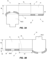
FIG. 3A is a cross-sectional, schematic view of a portion of the grid ofFIG. 1 with a liquid specimen applied to a first side of the grid. -
FIG. 3B is a cross-sectional, schematic view of a portion of the grid ofFIG. 1 with a liquid specimen applied to a second side of the grid. -
FIG. 4 is a schematic diagram of an electronic control system and a microcontroller. -
FIG. 5 is a flow chart depicting a method of fabricating the grid ofFIG. 1 . - Before any implementations of the disclosure are explained in detail, it is to be understood that the disclosure is not limited in its application to the details of construction and the arrangement of components set forth in the following description or illustrated in the following drawings. The disclosure is capable of other implementations and of being practiced or of being carried out in various ways.
- The present disclosure relates to a sample preparation system 10 for sampling a
liquid specimen 14. The sample preparation system 10 is configured to prepare theliquid specimen 14 for analysis by a charged particle microscope (e.g., a transmission electron microscope [TEM]). The illustrated application is only one example, and the sample preparation system 10 may be utilized in any sampling application, especially when sampling aliquid specimen 14. - As illustrated in
FIG. 1 , the sample preparation system 10 includes apipette 16 for placing theliquid specimen 14 and agrid 18 for holding theliquid specimen 14. Thepipette 16 is configured to place a droplet 19 of theliquid specimen 14 onto thegrid 18. In other embodiments, a different device may be used to place theliquid specimen 14 onto the grid 18 (e.g., a printer, syringe, etc.). Thepipette 16 is configured to place the droplets 19 onto asecond side 20 of thegrid 18. In alternate embodiments, thepipette 16 may place the droplets 19 onto afirst side 21 of thegrid 18. - The illustrated
grid 18 includes amesh 22 and afoil 26. Thefoil 26 defines thefirst side 21 of thegrid 18. Themesh 22 defines thesecond side 20 of thegrid 18. Themesh 22 and thefoil 26 are substantially the same shape and size. In the illustrated embodiment, both themesh 22 and thefoil 26 are circular in shape. In alternate embodiments, themesh 22 and thefoil 26 may be a different shape (e.g., square, rectangular, trapezoidal, etc.), or themesh 22 may have a different shape from the foil 26 (e.g., themesh 22 may be circular and thefoil 26 may be square). - The
mesh 22 includes a plurality ofgrid bars 46 defining a plurality ofopenings 50. As shown inFIGS. 2A and 2B , each of the illustratedopenings 50 is generally square in shape. In alternate embodiments, each of the plurality ofopenings 50 may have other shapes (e.g., circular, rectangular, hexagonal, oblong, etc.). The plurality of grid bars 46 forms an outer perimeter 54 of each of the plurality ofopenings 50. The outer perimeter 54 corresponds with and overlaps with the grid bars 46, as shown inFIG. 2A . Each of the plurality of grid bars 46 has awidth 56. In the present embodiment, thewidth 56 is 25 micrometers. In other embodiments, the grid bars 46 may have other widths in a range from 10 to 100 micrometers. - In the present embodiment, the
mesh 22 is hydrophilic and thefoil 26 is hydrophilic. In alternate embodiments, themesh 22 may not be hydrophilic, or thefoil 26 may not be hydrophilic, or both themesh 22 and thefoil 26 may not be hydrophilic. - The
foil 26 includes a plurality ofholes 58. In the illustrated embodiment, each of the plurality ofholes 58 is generally circular. In alternate embodiments, the plurality ofholes 58 may be different shapes (e.g., square, triangular, oblong, etc.). Subsets 59 of the plurality ofholes 58 are arranged in clusters 60. A cluster 60 is a collection ofholes 58 that is spaced from a similar collection ofholes 58. Each cluster 60 is aligned with one of theopenings 50 defined by themesh 22. The cluster 60 is separated from adjacent clusters 60 of the plurality ofholes 58 by adistance 61. Thedistance 61 may be greater than thewidth 56 of one of the plurality of grid bars 46. Thegrid bar 46 may be dome shaped such that acontact length 62 between thegrid bar 46 and thefoil 26 may be smaller or larger than themesh width 56. Thecontact length 62 between thegrid bar 46 and thefoil 26 is variable depending on the tension of thefoil 26. The tension of thefoil 26 determines what extent thefoil 26 follows the curve of thegrid bar 46. Thedistance 61 may be greater than thecontact length 62. In the present embodiment, thefoil 26 may be a plastic film. Amorphous carbon may be deposited onto the plastic film after which the plastic film may be dissolved. Alternatively, the plastic film may remain along with the amorphous carbon. In some embodiments, themesh 22 may be built upon thefoil 26 to form a one-piece mesh-foil structure and thefoil 26 may be made of a metal such as gold. In other embodiments, thefoil 26 may be made of a different material (e.g., plastic, glass, etc.). - A
back portion 66 of themesh 22 corresponds with and is at least partially in contact with thefoil 26. The subset 59 of the plurality ofholes 58 on thefoil 26 is configured to align with one of the plurality ofopenings 50. Eachhole 58 of the subset 59 is spaced apart from the outer perimeter 54 of thecorresponding opening 50. In the present embodiment, none of theholes 58 of the subset 59 partially overlaps the plurality of grid bars 46 that form the outer perimeter 54 of thecorresponding opening 50. Rather, asolid portion 70 of thefoil 26 is in contact with the outer perimeter 54. Thesolid portion 70 of thefoil 26 is continuous and does not include any of the plurality ofholes 58. Thesolid portion 70 may extend along theentire contact length 62. Theholes 58 are configured to align with theopening 50 to inhibit backside wetting (i.e., when a portion of theliquid specimen 14 leaks through theholes 58 and comes into contact with asecond side 74 of the foil 26). - Each of the plurality of
holes 58 in the cluster 60 is spaced apart from one another by acluster distance 57. Thecluster distance 57 may be less than thedistance 61 that adjacent clusters 60 are separated from one another. In alternate embodiments, such as when the amount of the plurality ofholes 58 is low, thecluster distance 57 may be more than thedistance 61. Thecluster distance 57 and thedistance 61 distinguish distinct clusters 60 from one another by arranging the plurality ofholes 58 at varied distances from one another. One cluster 60 may include any number ofholes 58, for example, between 1 and 1000. In the example shown inFIG. 2B , one cluster 60 includes nineholes 58. In alternate embodiments, one cluster 60 may include fewer ormore holes 58. The illustrated cluster 60 is arranged to create a square shape. The cluster 60 includes three holes on each side of the square shape. In alternate embodiments, the cluster 60 may be arranged in any of a plurality of different shapes (e.g., triangular, circular, rectangular, etc.). - In some embodiments, the
holes 58 may be evenly spaced and distributed across theentire foil 26. In such embodiments, the clusters 60 may be defined by the grid bars 46 of themesh 22. That is, holes 58 within the outer perimeter 54 of oneopening 50 may form a first cluster 60, whileholes 58 within the outer perimeter 54 of anotheropening 50 may form a second cluster 60.Holes 58 between adjacent clusters 60 (e.g., holes 58 that overlap with the grid bars 46) may not be considered part of any cluster. - The
mesh 22 has a mesh thickness of 15 micrometers. Thefoil 26 has a foil thickness of 10 nanometers. In alternate embodiments, themesh 22 and thefoil 26 may have other thicknesses. For example, themesh 22 may have a nominal mesh thickness in a range from 5-35 micrometers. Thefoil 26 may have a nominal foil thickness in a range from 5-50 nanometers. -
FIG. 3A illustrates aliquid specimen 14 applied onto thefirst side 21 of thegrid 18 such that theliquid specimen 14 is supported by thefoil 26. As shown in the illustrated embodiment, thefoil 26 is closed near thegrid bar 46. That is, none of the holes 80 in thefoil 26 partially overlaps one of the grid bars 46. Rather, a first hole 80 of the subset 59 (i.e., the hole 80 nearest the grid bar 46) is formed at ahole distance 78 from thegrid bar 46. Thehole distance 78 may be between 5 and 20 micrometers. In other embodiments, thehole distance 78 may be larger or smaller. For example, thehole distance 78 may be in a range from 1-100 micrometers. By closing thefoil 26 adjacent thegrid bar 46, theliquid specimen 14 is less likely to seep through a portion of thefoil 26 by clinging to thegrid bar 46. As such, backside wetting may be reduced. - In alternate embodiments, the clusters 60 may only partially align across the grid 18 (i.e., some clusters 60 may be perfectly aligned and some clusters 60 may have holes 80 overlapping the grid bar 46). These
grids 18 may still be usable by applying theliquid specimen 14 only to the clusters 60 having perfect alignment. Alternatively, the user may accept backside wetting inindividual openings 50. -
FIG. 3B illustrates aliquid specimen 14 applied onto thesecond side 20 of thegrid 18 such that theliquid specimen 14 is supported by thefoil 26 between the grid bars 46 of themesh 22. Similar to the scenario inFIG. 3A , thefoil 26 is closed near thegrid bar 46. As such, theliquid specimen 14 is less likely to seep through a portion of thefoil 26 adjacent the grid bar and cause backside wetting. -
FIG. 4 illustrates the sample preparation system 10 including amicromanipulator 88 to help align thefoil 26 with themesh 22. In some embodiments, themicromanipulator 88 is configured to detect the location of theholes 58 and the location of the grid bars 46. Themicromanipulator 88 then aligns thefoil 26 with themesh 22 such that each cluster 60 of theholes 58 is positioned within one of theopenings 50. More particularly, themicromanipulator 88 aligns thefoil 26 with themesh 22 such that none of theholes 58 partially overlaps with any of the grid bars 46. In other embodiments, themicromanipulator 88 may detect edges or other features of themesh 22 and thefoil 26 to properly align thefoil 26 with themesh 22. The illustrated sample preparation system 10 also includes anelectronic controller 90 configured to automatically or semi-automatically control themicromanipulator 88. Thecontroller 90 may include a programmable processor 94 (e.g., a microprocessor, a microcontroller, or another suitable programmable device) and amemory 98 such as a non-transitory memory. Thememory 98 may include, for example, aprogram storage area 102 and adata storage area 106. Theprogram storage area 102 and thedata storage area 106 can include combinations of different types ofmemory 98, such as read only memory ("ROM"), random access memory ("RAM") (e.g., dynamic RAM ["DRAM"], synchronous DRAM ["SDRAM"], etc.), electrically erasable programmable read-only memory ("EEPROM"), flash memory, a hard disk, an SD card, or other suitable magnetic, optical, physical, electronic memory devices, or other data structures. Programming may be coded or learned. - As one example, the
electronic controller 90 may be configured to control rotation and movement of themicromanipulator 88. Theelectronic controller 90 may also be configured to control the position of themicromanipulator 88 in 3-dimensional space, e.g., to move or rotate themicromanipulator 88 to align themesh 22 with thefoil 26, which may include moving in the X-direction, the Y-direction, and/or the Z-direction, in any combination or orientation. - In some embodiments, the
foil 26 may be initially solid and not include the plurality ofholes 58. In such embodiments, theback portion 66 of themesh 22 may be aligned with thefoil 26 and attached to thefoil 26. The plurality ofholes 58 may then be formed in thefoil 26 after thefoil 26 is coupled to themesh 22. For example, a patterning device may pattern the plurality ofholes 58 on a portion of thefoil 26 corresponding to theopening 50. The patterning device may be controlled by theelectronic controller 90. This may occur using wafer-based manufacturing (i.e., thegrid 18 is produced on a silicon wafer). Wafer-based manufacturing allows for an addition of custom fiducial markers and patterns which aid in locating and identifying particular regions of thegrid 18 at several length scales: by eye, in an optical microscope, and in the electron microscope. These fiducial markers aid in the patterning of the plurality ofholes 58 on thefoil 26. In other embodiments, themicromanipulator 88 may align a template to thepre-aligned mesh 22 andfoil 26. The template may be configured to aid in the patterning of the plurality ofholes 58 on thefoil 26. Alternatively, themesh 22 and thefoil 26 may not be aligned and instead the mesh may be built upon the foil to form the one-piece closed mesh-foil structure. The patterning device may then pattern the plurality ofholes 58 on the portion of the foil corresponding to theopening 50. In alternate embodiments, thefoil 26 may include the plurality ofholes 58 and apre-made mesh 22 may be aligned with the foil using themicromanipulator 88. Alternatively, thefoil 26 may include the plurality ofholes 58 and themesh 22 may be built upon thefoil 26 to create the integrally formed one-piece mesh-foil structure. - In further embodiments, the
foil 26 may haveholes 58 all over and some of theholes 58 may be filled after thefoil 26 is attached to themesh 22. For example, if thefoil 26 is positioned on themesh 22 such that someholes 58 do partially overlap with the grid bars 46, theholes 58 that partially overlap with the grid bars 46 may be filled with a suitable material or filler to close thoseholes 58. Thefoil 26 may be attached to themesh 22 using themicromanipulator 88, or themesh 22 may be built upon thefoil 26 to form the one-piece mesh-foil structure. -
FIG. 5 is a flowchart depicting amethod 500 of fabricating thegrid 18 for sampling theliquid specimen 14 for analysis in a charged particle microscope (e.g., a transmission electron microscope, scanning electron microscope, etc.). Although the method includes particular steps, not all of the steps need to be performed or need to be performed in the order presented. In some embodiments, the method may include additional steps. At least some of the method may be carried out by theelectronic controller 90. - At
step 501, a user provides thefoil 26. Step 501 may also include the user providing themesh 22. Thefoil 26 may include the plurality ofholes 58. The subset 59 of the plurality ofholes 58 is arranged in the cluster 60. The cluster 60 is separated from adjacent clusters 60 of the plurality ofholes 58 by thedistance 61. Alternatively, thefoil 26 may not include the plurality ofholes 58 at thisstep 501. - At
step 502, themesh 22 is added to thefoil 26. This may be done by a user or by amicromanipulator 88. Themesh 22 includes the plurality of grid bars 46. The plurality of grid bars 46 defines the plurality ofopenings 50 and forms the outer perimeter 54 of eachopening 50. Each of the plurality ofopenings 50 is generally square in shape. The mesh may be built upon the foil to form the one-piece closed mesh-foil structure. The cluster 60 is aligned with each of the plurality ofopenings 50 after themesh 22 and thefoil 26 are coupled. Themesh 22 may be added to thefoil 26 using any of a plurality of different adhesives or adhesive techniques. In some embodiments, an adhesive or adhesive technique may not be used. - At
step 503, eachhole 58 of the subset 59 is spaced from the outer perimeter 54 of thecorresponding opening 50 defined by the plurality of grid bars 46. In some embodiments of the present method, step 503 may include aligning thefoil 26 with themesh 22 such that none of theholes 58 of the subset 59 partially overlaps the plurality of grid bars 46. Step 503 may further include filling anyholes 58 of the subset 59 that partially overlap the plurality of grid bars 46. In some embodiments, a patterning device may pattern the plurality ofholes 58 on the portion of thefoil 26 corresponding to theopenings 50. The patterning device may not pattern holes 58 on the outer perimeter 54. Further method steps and intermediary method steps are apparent from the description above and the operational description below. - In operation, the
foil 26 and themesh 22 are aligned to form thegrid 18 such that theholes 58 only align with theopening 50. Theholes 58 do not partially overlap with the plurality of grid bars 46. Theliquid specimen 14 is pipetted onto thegrid 18, and the user blots thegrid 18 with filter paper. Thegrid 18 is then inserted into, for example, liquid ethane to vitrify the liquid solution. Thegrid 18 may be submerged into a bath of liquid ethane or a jet of liquid ethane may be focused on thegrid 18. Thegrid 18 may then be analyzed by the microscope (e.g., TEM). It should be noted that other preparation techniques may be used. For example, a printer may print theliquid specimen 14 onto thegrid 18, and the user may not be required to blot the grid. - Aligning the subset of holes with each of the plurality of openings provides advantages. If a hole partially overlaps with the
grid bar 46, back side wetting may occur due to the hydrophilicity of the grid bars 46. This may cause a backside meniscus to grow from the grid bars 46 inward toward the center of theopening 50. This may lead to poorlyreproducible sample thickness 86 and thick ice unsuitable for cryo-EM acquisition in large areas of thegrid 18. By keeping thefoil 26 solid near the grid bars 46, back side wetting may be less likely to occur and there may be better control oversample thickness 86. - Various features and advantages of the invention are set forth in the following claims.
Claims (20)
- A grid for sampling a liquid specimen, the grid comprising:a mesh including a plurality of grid bars defining a plurality of openings, the plurality of grid bars forming an outer perimeter of each opening; anda foil coupled to the mesh, the foil including a plurality of holes, wherein a subset of the plurality of holes is aligned with each of the plurality of openings, and wherein each hole of the subset is spaced from the outer perimeter of the corresponding opening defined by the plurality of grid bars.
- The grid of claim 1, wherein each of the plurality of openings is generally square.
- The grid of claim 2, wherein each of the plurality of holes is generally circular.
- The grid of claim 1, wherein the foil is a plastic film.
- The grid of claim 1, wherein the mesh is hydrophilic.
- The grid of claim 1, wherein each subset of the plurality of holes is arranged in a cluster separated from adjacent clusters of the plurality of holes by a distance greater than a width of one of the plurality of grid bars.
- The grid of claim 1, wherein the mesh has a mesh thickness of 5-35 micrometers.
- The grid of claim 1, wherein the foil has a foil thickness of 10-15 nanometers.
- A grid for sampling a liquid specimen, the grid comprising:a mesh including a plurality of grid bars defining a plurality of openings, the plurality of grid bars forming an outer perimeter of each opening; anda foil coupled to the mesh, the foil including a plurality of holes, wherein a subset of the plurality of holes is aligned with each of the plurality of openings, and wherein none of the holes of the subset partially overlaps the plurality of grid bars forming the outer perimeter of the corresponding opening.
- The grid of claim 9, wherein each of the plurality of openings is generally square.
- The grid of claim 10, wherein each of the plurality of holes is generally circular.
- The grid of claim 9, wherein the foil is a plastic film.
- The grid of claim 9, wherein the mesh is hydrophilic.
- The grid of claim 9, wherein each subset of the plurality of holes is arranged in a cluster separated from adjacent clusters of the plurality of holes by a distance greater than a width of one of the plurality of grid bars.
- The grid of claim 9, wherein the mesh has a mesh thickness of 5-35 micrometers.
- The grid of claim 9, wherein the foil has a foil thickness of 10-15 nanometers.
- A method of fabricating a grid for sampling a liquid specimen, the method comprising:providing a foil including a plurality of holes;coupling a mesh to the foil, the mesh including a plurality of grid bars defining a plurality of openings, the plurality of grid bars forming an outer perimeter of each opening, wherein a subset of the plurality of holes is aligned with each of the plurality of openings; andspacing each hole of the subset from the outer perimeter of the corresponding opening defined by the plurality of grid bars.
- The method of claim 17, wherein spacing each hole of the subset from the outer perimeter of the corresponding opening includes aligning the foil with the mesh such that none of the holes of the subset partially overlaps the plurality of grid bars.
- The method of claim 17, wherein spacing each hole of the subset from the outer perimeter of the corresponding opening includes filling any holes of the subset that partially overlap the plurality of grid bars.
- The method of claim 17, wherein spacing each hole of the subset from the outer perimeter of the corresponding opening includes forming the plurality of holes in the foil after the foil is coupled to the mesh.
Applications Claiming Priority (1)
| Application Number | Priority Date | Filing Date | Title |
|---|---|---|---|
| US202363579234P | 2023-08-28 | 2023-08-28 |
Publications (1)
| Publication Number | Publication Date |
|---|---|
| EP4517292A1 true EP4517292A1 (en) | 2025-03-05 |
Family
ID=92593075
Family Applications (1)
| Application Number | Title | Priority Date | Filing Date |
|---|---|---|---|
| EP24196953.4A Pending EP4517292A1 (en) | 2023-08-28 | 2024-08-28 | Liquid specimen grid for transmission electron microscope |
Country Status (4)
| Country | Link |
|---|---|
| US (1) | US20250076159A1 (en) |
| EP (1) | EP4517292A1 (en) |
| JP (1) | JP2025033002A (en) |
| CN (1) | CN119534503A (en) |
Families Citing this family (1)
| Publication number | Priority date | Publication date | Assignee | Title |
|---|---|---|---|---|
| US12366509B2 (en) * | 2019-10-04 | 2025-07-22 | Mitegen, Llc | Sample supports and sample cooling systems for cryo-electron microscopy |
Citations (3)
| Publication number | Priority date | Publication date | Assignee | Title |
|---|---|---|---|---|
| JP2008235192A (en) * | 2007-03-23 | 2008-10-02 | Seiko Epson Corp | Manufacturing method of microgrid |
| US20220291098A1 (en) * | 2019-10-04 | 2022-09-15 | Mitegen, Llc | Sample supports and sample cooling systems for cryo-electron microscopy |
| WO2023059493A1 (en) * | 2021-10-05 | 2023-04-13 | The Regents Of The University Of California | Apparatus for preparing electron microscopy samples and methods of use thereof |
Family Cites Families (3)
| Publication number | Priority date | Publication date | Assignee | Title |
|---|---|---|---|---|
| EP2278306A1 (en) * | 2009-07-13 | 2011-01-26 | Fei Company | Method for inspecting a sample |
| EP2757402B1 (en) * | 2013-01-22 | 2016-03-30 | FEI Company | Method of observing samples with a fluorescent microscope |
| US11101104B2 (en) * | 2019-08-30 | 2021-08-24 | Fei Company | Multi modal cryo compatible GUID grid |
-
2024
- 2024-08-23 US US18/813,403 patent/US20250076159A1/en active Pending
- 2024-08-27 CN CN202411182533.6A patent/CN119534503A/en active Pending
- 2024-08-27 JP JP2024145059A patent/JP2025033002A/en active Pending
- 2024-08-28 EP EP24196953.4A patent/EP4517292A1/en active Pending
Patent Citations (3)
| Publication number | Priority date | Publication date | Assignee | Title |
|---|---|---|---|---|
| JP2008235192A (en) * | 2007-03-23 | 2008-10-02 | Seiko Epson Corp | Manufacturing method of microgrid |
| US20220291098A1 (en) * | 2019-10-04 | 2022-09-15 | Mitegen, Llc | Sample supports and sample cooling systems for cryo-electron microscopy |
| WO2023059493A1 (en) * | 2021-10-05 | 2023-04-13 | The Regents Of The University Of California | Apparatus for preparing electron microscopy samples and methods of use thereof |
Non-Patent Citations (1)
| Title |
|---|
| N.N.: "GRIDS including TEM Support Films, Grid Staining, & Grid Storage", 20 March 2017 (2017-03-20), pages 1 - 55, XP093082867, Retrieved from the Internet <URL:http://scienceservices.de/media/pdf/ScienceServices_EMS_Catalogue_Grids.pdf> * |
Also Published As
| Publication number | Publication date |
|---|---|
| CN119534503A (en) | 2025-02-28 |
| US20250076159A1 (en) | 2025-03-06 |
| JP2025033002A (en) | 2025-03-12 |
Similar Documents
| Publication | Publication Date | Title |
|---|---|---|
| US20250076159A1 (en) | Liquid specimen grid for transmission electron microscope | |
| EP2612128B1 (en) | Device and method for the automated isolation and transfer of at least one microscopic sample from a sample carrier to a collecting system | |
| EP2979078B1 (en) | Microscope slides with quality controls thereon | |
| US20160351374A1 (en) | Thin-ice grid assembly for cryo-electron microscopy | |
| DE112016005255B4 (en) | biomolecule measuring device | |
| EP3169986B1 (en) | Electron microscope and method for transmission electron microscopy imaging of sample arrays | |
| DE10349847B3 (en) | Positioning device and method for the transmission of electronic components | |
| AT507079A4 (en) | Specimens preparing method for cryo-electron microscope, involves moving-away blotting device from carrier due to change in optical properties of absorbing medium detected by sensor device | |
| DE112015000920T5 (en) | Microfluidic chip with conical, bead-trapping cavities and method of making same | |
| EP4407291A2 (en) | Sample supports and sample cooling systems for cryo-electron microscopy | |
| DE60311973T2 (en) | SUBSTRATE AND METHOD FOR MEASURING ELECTROPHYSIOLOGICAL PROPERTIES OF CELL MEMBRANES | |
| EP3559630A1 (en) | Device and method for wetting biological material | |
| CN113192816A (en) | Electron microscope carrier net, preparation method thereof and microscope product | |
| EP2478378B1 (en) | Object support retainer | |
| EP1752221B1 (en) | Automatic microinjection apparatus and cell trapping plate | |
| WO2014009066A1 (en) | Method and analysis device for microscopic examination of a tissue section or cell smear | |
| EP1537402B1 (en) | Device and method for carrying out immunological marking techniques for thin-sectioned tissue | |
| EP0961654A1 (en) | System for producing multiple diagnostic test elements | |
| WO2015128256A1 (en) | Porous membrane patterning technique | |
| US20260024717A1 (en) | Grid for transmission electron microscope | |
| WO2014009067A1 (en) | Device and method for incubating patient samples | |
| US20250079117A1 (en) | Tem grids with liquid spreading lanes | |
| CN215342494U (en) | A kind of electron microscope carrier net and electron microscope | |
| DE102024101875A1 (en) | IMMERSION SENSOR FOR ELECTROCHEMICAL MEASUREMENTS AND METHOD FOR MANUFACTURING AN IMMERSION SENSOR | |
| WO2002102503A1 (en) | Reaction vessel for producing samples |
Legal Events
| Date | Code | Title | Description |
|---|---|---|---|
| PUAI | Public reference made under article 153(3) epc to a published international application that has entered the european phase |
Free format text: ORIGINAL CODE: 0009012 |
|
| STAA | Information on the status of an ep patent application or granted ep patent |
Free format text: STATUS: THE APPLICATION HAS BEEN PUBLISHED |
|
| AK | Designated contracting states |
Kind code of ref document: A1 Designated state(s): AL AT BE BG CH CY CZ DE DK EE ES FI FR GB GR HR HU IE IS IT LI LT LU LV MC ME MK MT NL NO PL PT RO RS SE SI SK SM TR |
|
| STAA | Information on the status of an ep patent application or granted ep patent |
Free format text: STATUS: REQUEST FOR EXAMINATION WAS MADE |
|
| 17P | Request for examination filed |
Effective date: 20250904 |