EP4517257A1 - Method for determining an estimated angle of rotation of a rotational joint of a working machine - Google Patents
Method for determining an estimated angle of rotation of a rotational joint of a working machine Download PDFInfo
- Publication number
- EP4517257A1 EP4517257A1 EP23193667.5A EP23193667A EP4517257A1 EP 4517257 A1 EP4517257 A1 EP 4517257A1 EP 23193667 A EP23193667 A EP 23193667A EP 4517257 A1 EP4517257 A1 EP 4517257A1
- Authority
- EP
- European Patent Office
- Prior art keywords
- rotation
- rotational
- counter
- angle
- values
- Prior art date
- Legal status (The legal status is an assumption and is not a legal conclusion. Google has not performed a legal analysis and makes no representation as to the accuracy of the status listed.)
- Pending
Links
Images


Classifications
-
- E—FIXED CONSTRUCTIONS
- E02—HYDRAULIC ENGINEERING; FOUNDATIONS; SOIL SHIFTING
- E02F—DREDGING; SOIL-SHIFTING
- E02F9/00—Component parts of dredgers or soil-shifting machines, not restricted to one of the kinds covered by groups E02F3/00 - E02F7/00
- E02F9/26—Indicating devices
- E02F9/264—Sensors and their calibration for indicating the position of the work tool
Definitions
- the present invention relates to a method for determining an estimated angle of rotation of a rotational joint of a working machine, as well as to a computing unit and a computer program for performing the method.
- the implement consists of a kinematic chain of links, which are movable relative to each other.
- the implement consists amongst others of an under carriage, an upper carriage, a boom, an arm and a bucket.
- These links are connected with joints and are forced into movement usually by hydraulic (such as hydraulic cylinders) or electric actuators, controlled by the machine operator with the help of joysticks or other HMI-components.
- hydraulic such as hydraulic cylinders
- electric actuators controlled by the machine operator with the help of joysticks or other HMI-components.
- a prismatic joint is used to realize the telescope-feature of a telescopic handler.
- rotational joints are used.
- the links of a standard excavator are connected with pins, which are rotational joints.
- the connection between upper carriage and undercarriage is physically a rotational joint.
- vehicles may be equipped with assistance and automatization features, in order to make the operation of the machine less exhausting and safer.
- assistance and automatization features For the implementation of most assistance and automatization functions, the knowledge of the actual implement pose is crucial. In case of rotational joints, this can be achieved by sensing or estimating the relative angles of rotation.
- the invention provides a method for determining an estimated angle of rotation of a rotational joint of a working machine as well as a computing unit and a computer program for performing the method according to the independent claims.
- Dependent claims relate to preferred embodiments of the invention.
- one or more first values which indicate an angle of rotation of the rotational joint, are determined from a counter that is determined based on measurements of a rotational speed sensor
- one or more second values which indicate a linear acceleration and/or a rotational rate, are determined from measurements of at least one inertial motion unit that is attached to a part of the two parts of the working machine connected by the rotational joint.
- a sensor fusion algorithm is applied to the one or more first values and the one or more second values in order to determine the estimated angle of rotation.
- the method allows an accurate estimation of the angle of rotation for rotational joints that, in a typical orientation of the working machine, are at least partially or essentially parallel to the gravitational field, such that a determination of the angle of rotation based on measurements of the orientations of the two parts with respect to the gravitational field is imprecise or not possible.
- errors due to the discontinuous measurements based on the counter signal are corrected by the measurements of the inertial motion unit, and errors due to a drift of the measurements of the inertial motion unit are corrected by the measurements of the angle speed sensor.
- a dedicated angle sensor that measures the rotational angle directly (encoder or the like), and which therefore has to be placed directly on the rotational joint, is not necessary.
- Such dedicated angle sensors have the disadvantage that they are complicated to integrate on the working machine and that they are exposed to rough working conditions like dirt and mechanical stress.
- special design measures have to be taken when integrating such dedicated angle sensors.
- the possible values of the counter form a discrete subset of the real numbers, such as integer numbers.
- the term "discrete set” means a set that can be mapped to theetter number.
- the term “count” means the change from one value of the counter to the next higher or next lower possible value of the counter.
- Each count of the counter may correspond to the same angular distance (i.e. angle difference).
- different counts of the counter may correspond to different angular distances. In the latter case, for example, a mapping between the counts of the counter and the corresponding angular distances could be provided or angular distances could be proportional to distances of the counts of the counter (i.e. the discrete subset is different from the integers).
- inertial motion unit means a measuring unit, that is configured to measure linear acceleration and/or rotational rate, i.e. the linear acceleration and/or rotational rate that the inertial motion unit is subjected to.
- IMU will be used for "inertial motion unit”. In case of more than one IMU, different IMUs may be attached to different ones of the two parts connected by the rotational joint.
- the sensor fusion algorithm comprises a Kalman filter or a complimentary filter or recursive Bayes estimation, for example.
- the sensor fusion algorithm may be based on a physical model of the working machine and/or the rotational joint and/or the parts connected by the rotational joint.
- the geometric relationship between the rotational joint and the at least one IMU may be incorporated. That is, the second values (measured by the at least one IMU) may be transformed from a (at least one) coordinate system of the at least one IMU into a coordinate system of the rotational joint. Such a transformation may be done prior to applying the sensor fusion algorithm or be part of the sensor fusion algorithm (e.g. for sensor fusion algorithms, such as a Kalman filter, that utilize a model, the transformation may be included in the model). In case values for the linear acceleration that are measured by an IMU are used, the IMU should not be placed on the axis of the rotational joint.
- the method of claim further comprises determining the counter based on a signal output of the rotational speed sensor; wherein the counter is increased or decreased based on a signal indicating the direction of the rotation. In particular this allows to apply the method for rotations, in which the direction of rotation changes.
- the signal output has features which indicate rotation, wherein the counter is increased or decreased each time a feature occurs.
- features is the signal output correspond to features on a rotating element (e.g. gear wheel), their distribution and angular distance are known.
- the signal output includes rising edges and falling edges, wherein the counter is increased or decreased each time a rising edge and/or a falling edge occurs.
- the signal output is a rectangle signal output. Such signal outputs are easily processed using common electronic circuitry.
- the signal indicating the direction of rotation is provided by the rotational speed sensor.
- the rotational speed sensor may measure the direction of rotation directly.
- the signal indicating the direction of rotation is determined based on the measurements of at least one inertial motion unit. That is, the direction of rotation is determined (calculated) from the acceleration and/or rotational rate measured by the IMU (wherein geometric relation may be incorporated).
- the method further comprises resetting the counter at a reset time, wherein the estimated angle of rotation is determined as estimated relative angle with respect to the angle of rotation at the reset time.
- the reset may be initiated based on a reset signal from a user of the working machine, for example. This allows to set a reference direction for the execution of automatic functions of the working machine.
- the at least one inertial motion unit comprises more than one inertial motion unit, wherein two different inertial motion unit are attached to different ones of the two parts connected by the rotational joint.
- a computing unit e.g. a control unit of a working machine, is set up, in particular by executing one or more computer programs, to carry out a method according to the invention.
- a machine-readable storage medium is provided with a computer program stored thereon as described above.
- Suitable storage media or data carriers for providing the computer program are, in particular, magnetic, optical and electrical memories, such as hard disks, flash memories, EEPROMs, DVDs and others. It is also possible to download a program via computer networks (Internet, Intranet, etc.). Such a download can be wired or wireless (e.g. via a WLAN network, a 3G, 4G, 5G or 6G connection, etc.).
- FIG. 1 shows an excavator 2 as an example for a working machine.
- the excavator 2 comprises as parts an under-carriage 4 and an upper-carriage 6, which are rotatably connected by a rotational joint 8.
- the excavator 2 comprises boom elements 10 rotatably connected to each other, with one of the boom elements 10 being rotatably connected to the upper-carriage 6.
- the excavator 2 further comprises an arm 12 rotatably connected to the other one of the boom elements 10 and a bucket 14 rotatably connected to the arm 12.
- the rotatable connections between the upper-carriage 6 and one of the boom elements 10, between the two boom elements 10, between the other one of the boom elements 10 and the arm 12, and between the arm 12 and the bucket 14 are in each case achieved by rotational joints 16.
- these parts of the excavator can be seen as links of a kinematic chain.
- the pose of this kinematic chain can, for example, be determined from the angles of rotation of the rotational joints 8, 16, i.e. from the respective relative angles between the links connected by the rotational joints.
- IMUs (not shown) to each of these links, whereby the IMUs measure linear accelerations, from which the angle of the link with respect to the gravitational vector 18 can be derived.
- the relative rotational movement between the under-carriage 4 and the upper-carriage 6 may be driven by a slewing gear drive 20 that includes a motor (e.g. a hydraulic motor or an electric motor).
- a gear ring interacts with a pinion attached to the output shaft of the motor, such that a transmission ratio between the gear ring and the motor is present (the gear ring may be attached on the under-carriage and the motor may be attached to the upper-carriage).
- the rotational speed of the slewing gear drive 20 can be derived from measurements of a rotational speed sensor 22, which determines the rotational speed of the motor, for example.
- the rotational speed may be used in control methods for controlling the rotation of the upper-carriage with respect to the under-carriage.
- an IMU 24 and a control device 26 are shown.
- the IMU 24 is attached to the upper-carriage 6 and configured to measure a linear acceleration and/or a rotational rate of the IMU.
- the control device 26 may be configured to receive measurement results or measurement values from the rotational speed sensor 22 and the IMU 24.
- the control device 26 is connected to the rotational speed sensor 22 and the IMU 24 by electric signal lines to obtain measurement values.
- the control device 26 may be configured to implement a method according to the invention, e.g. by executing a respective computer program.
- FIG. 2 illustrates the working principle of an exemplary rotational speed sensor 22.
- the shown rotational speed sensor 22 is an inductive sensor, for example.
- the rotational speed sensor may be realized as an inductive sensor, a capacitive sensor, a Hall effect sensor, an optical sensor, or the like.
- the rotational speed sensor 22 is positioned adjacent to a gear wheel 32 (only partially shown), which has a known number of teeth.
- the gear wheel may be attached to the output shaft of the motor of the slewing gear drive.
- the gear wheel is the pinion attached to the output shaft of the motor.
- the rotational speed sensor 22 senses the change in inductance, when the teeth pass the measuring tip 30.
- the frequency of the corresponding signal is proportional to the rotational speed of the gear wheel 32 (assuming, the teeth are equally spaced from each other).
- the rotational speed sensor 22 is configured to generate a corresponding rectangle signal output, such as shown in Figure 3 .
- the rotational speed sensor 22 is optionally configured to generate a directional signal indicating the direction (clockwise/counter-clockwise) of the rotation of the gear wheel 32.
- Figure 3 shows an actual angle of rotation, signals obtained from the actual angle of rotation by an exemplary rotational speed sensor (such as shown in Figure 2 ), and values of an angle of rotation derived therefrom.
- the figure includes four sub-charts showing parameters as a function of time t. Units of the parameters may be chosen appropriately (not shown).
- the first (upper-most) sub-chart shows the actual angle of rotation 40 of the gear wheel that is used for sensing the rotational speed (e.g. gear wheel 32 in Figure 2 ). This is equal to the actual angle of rotation of the axis, to which the gear wheel is attached (e.g. output shaft of the motor of the slew gear drive 20 in Figure 1 ).
- the second sub-chart shows a rectangle signal output 42 generated by the rotational speed sensor. As can be seen, the frequency in the second phase is higher than in the third phase due to the speed of the rotation being higher.
- the third sub-chart shows a directional signal 44 generated by the rotational speed sensor.
- the fourth sub-chart shows a counter 46 that is determined based on the rectangle signal 42 and the directional signal 44. It is assumed that the counter is integer-valued. In order to determine the counter 46, the counter is increased by one at each edge (rising and falling edges) of the rectangle signal output 42, when the directional signal 44 indicates a rotation in the first direction, and the counter decreased by one at each edge of the rectangle signal 42, when the directional signal 44 indicates a rotation in the second direction. An approximated angle of rotation 50 (of the gear wheel) is obtained by multiplying the counter 46 with the angular distance between two consecutive edges of the teeth of the gear wheel, to which the edges of the rectangular signal correspond (it is assumed, that the angular distance between two consecutive edges is the same for all edges).
- the direction of rotation may be determined from measurements of another sensor, e.g. IMU 24 shown in Figure 1 . While in the shown example the counter is increased or decreased at each edge, alternatively, the counter may be increased or decreased only at rising edges or only at falling edges. Other types of rotational speed sensors may generate a different signal output (e.g. pulses).
- the counter is increased/decreased when a feature (i.e. a specific change) in the signal output occurs which indicates rotation.
- the features in the signal output correspond to features (e.g. teeth or other markings) positioned in a known manner on a rotating element (e.g. gear wheel or encoder) that is sensed by the rotational speed sensor. Therefore, the features in the signal output indicate a rotation and are indicative for the angular distance of counts (due to the known positioning of the corresponding features on the rotation element).
- the values of the angle of rotation ⁇ of the rotational joint determined by this formula may be considered as (first) values, which indicate an angle of rotation of the rotational joint.
- the discontinuous (discrete) nature of the counter x leads to an inaccuracy in that the values of the angle of rotation ⁇ of the rotational joint determined by this formula are a step-wise approximation of the actual angle of rotation of the rotational joint.
- a sensor fusion algorithm is used, whereby the values of the angle of rotation ⁇ of the rotational joint, which are determined based on the counter, are combined with values of acceleration and/or rotational rate obtained from an IMU. This allows to obtain a continuous and precise estimation for the actual angle of rotation of the rotational joint.
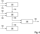
- FIG. 4 shows a flow chart according to embodiments of the invention.
- the flow chart pertains to a method for determining an estimated angle of rotation of a rotational joint of a working machine.
- the rotational joint connects two parts of the working machine to enable a rotational movement of the two part with respect to each other; i.e. the two parts are links or groups of links of a kinematic chain.
- a rotational speed sensor is positioned to generate a signal output (e.g. rectangle signal output) that has features (i.e. specific changes in the signal output) that can be counted, wherein differences between consecutive features (i.e. counts) correspond to angles distances. For example, a frequency of these features is directly or indirectly (e.g.
- At least one IMU in presence of a transmission gear having a transmission ratio unequal one) proportional to a rotational speed of the rotational joint.
- at least one IMU is attached to the two parts of the working machine. That is, if only one IMU is used, it is attached to one of the two parts; in particular, to that part, which is rotating during typical working conditions of the working machine. If more than one IMU is used, different IMUs may be attached to different parts of the two parts.
- the method may be performed by a control device (computing unit) of the working machine that includes the rotational joint.
- a counter 116 is determined from the signal output 112 of the rotational speed sensor and a signal 114 indicating the direction of the rotation.
- the signal output 112 of the rotational speed sensor is, for example, a rectangle signal generated by the rotational speed sensor and the signal 114 indicating the direction of the rotation is, for example, a directional signal generated by the rotational speed sensor. If the rotational speed sensor does not generate a directional signal, the direction of the rotation may be indicated by another sensor, e.g. the IMU, or determined from measurements of such a sensor.
- step 120 one or more first values 126, which indicate an angle of rotation of the rotational joint, are determined (also denoted as one or more first values 126 of an angle of rotation of the rotational joint).
- the one or more values first values 126, which indicate an angle of rotation of the rotational joint, are determined from the counter 116, wherein a known value 122 (or values) is used, which indicates the angular distance to which each count of the counter 116 corresponds. For example, the number of teeth on the gear wheel for the rotational speed sensor explained with respect to Figures 2 and 3 .
- the determination is additionally based on a transmission ratio 124 between the rotational movement for which the rotational speed sensor is acquiring measurement and the rotational movement of the rotational joint.
- the one or more first values 126 of the angle of rotation are essentially determined as product of the counter with the know angular distance (corresponding to each count) and with, if present (i.e. unequal one), the transmission ratio.
- the counter may have non-integer values (such that differences between consecutive values of the counter are proportional to the different angular distances) or a sum of the angular distances corresponding the counts may be formed and multiplied with the transmission ratio (if present), in order to determine the one or more first values 126 of an angle of rotation of the rotational joint.
- Steps 110 and 120 correspond to the procedure as explained in the description of Figures 2 and 3 .
- one or more values denoted as one or more second values 136, which indicate a linear acceleration and/or a rotational rate, are determined (also denoted as one or more second values 136 of a linear acceleration and/or a rotational rate).
- the one or more second values 136 which indicate a linear acceleration and/or a rotational rate, are determined from measurements of the at least one IMU. That is, measurement values 132 linear acceleration and/or a rotational rate are received from the at least one IMU.
- these measurement values are further processed in step 130. For example, a coordinate transformation into a coordinate system of the rotational joint may be performed and/or a filtering of the received values (e.g. to discard outliers). If no further processing takes place, the received measurement values are used directly as the one or more second values 136 of a linear acceleration and/or a rotational rate (i.e. the determination in step 130 consists in the receiving of the measurement values only).
- a sensor fusion algorithm (such as a Kalman filter or a complimentary filter) is applied to the one or more first values 126 of the angle of rotation and the one or more second values 136 of a linear acceleration and/or a rotational rate, in order to determine an estimated angle of rotation 146.
Landscapes
- Engineering & Computer Science (AREA)
- Mining & Mineral Resources (AREA)
- Civil Engineering (AREA)
- General Engineering & Computer Science (AREA)
- Structural Engineering (AREA)
- Length Measuring Devices With Unspecified Measuring Means (AREA)
Abstract
The invention concerns a method for determining an estimated angle of rotation (146) of a rotational joint (8) of a working machine (2), wherein the rotational joint (8) connects two parts (4, 6) of the working machine to enable a rotational movement of the two part with respect to each other. The method comprises determining (120) one or more first values (126), which indicate an angle of rotation of the rotational joint (8), from a counter (46, 116) that is determined based on measurements of a rotational speed sensor (22), wherein each count of the counter (46, 116) correspond to a respective angle distance; determining (130) one or more second values (136), which indicate a linear acceleration and/or a rotational rate, from measurements of at least one IMU (24), each of the at least one IMU attached to one of the two parts (6) that are connected by the rotational joint (8); and applying (140) a sensor fusion algorithm to the one or more first values (126) and one or more second values (136) in order to determine the estimated angle of rotation (146).
Description
- The present invention relates to a method for determining an estimated angle of rotation of a rotational joint of a working machine, as well as to a computing unit and a computer program for performing the method.
- Mobile applications like excavators, wheel loaders, telehandlers etc. are equipped with some sort of kinematic structure or implement to fulfil certain working tasks. These implements are designed in a way to operate attached working tools. Therefore, the implement consists of a kinematic chain of links, which are movable relative to each other. In the example of a standard excavator the implement consists amongst others of an under carriage, an upper carriage, a boom, an arm and a bucket. These links are connected with joints and are forced into movement usually by hydraulic (such as hydraulic cylinders) or electric actuators, controlled by the machine operator with the help of joysticks or other HMI-components. There are different kinds of joints used in mobile applications. For example, a prismatic joint is used to realize the telescope-feature of a telescopic handler. Often rotational joints are used. For example, the links of a standard excavator are connected with pins, which are rotational joints. Further, the connection between upper carriage and undercarriage (the slew) is physically a rotational joint.
- With the increasing electronification of mobile machinery, vehicles may be equipped with assistance and automatization features, in order to make the operation of the machine less exhausting and safer. For the implementation of most assistance and automatization functions, the knowledge of the actual implement pose is crucial. In case of rotational joints, this can be achieved by sensing or estimating the relative angles of rotation.
- The invention provides a method for determining an estimated angle of rotation of a rotational joint of a working machine as well as a computing unit and a computer program for performing the method according to the independent claims. Dependent claims relate to preferred embodiments of the invention.
- According to the method one or more first values, which indicate an angle of rotation of the rotational joint, are determined from a counter that is determined based on measurements of a rotational speed sensor, and one or more second values, which indicate a linear acceleration and/or a rotational rate, are determined from measurements of at least one inertial motion unit that is attached to a part of the two parts of the working machine connected by the rotational joint. A sensor fusion algorithm is applied to the one or more first values and the one or more second values in order to determine the estimated angle of rotation. The method allows an accurate estimation of the angle of rotation for rotational joints that, in a typical orientation of the working machine, are at least partially or essentially parallel to the gravitational field, such that a determination of the angle of rotation based on measurements of the orientations of the two parts with respect to the gravitational field is imprecise or not possible. Particularly, errors due to the discontinuous measurements based on the counter signal are corrected by the measurements of the inertial motion unit, and errors due to a drift of the measurements of the inertial motion unit are corrected by the measurements of the angle speed sensor.
- Further, a dedicated angle sensor that measures the rotational angle directly (encoder or the like), and which therefore has to be placed directly on the rotational joint, is not necessary. Such dedicated angle sensors have the disadvantage that they are complicated to integrate on the working machine and that they are exposed to rough working conditions like dirt and mechanical stress. Typically, special design measures have to be taken when integrating such dedicated angle sensors.
- The possible values of the counter form a discrete subset of the real numbers, such as integer numbers. The term "discrete set" means a set that can be mapped to the naturel number. The term "count" means the change from one value of the counter to the next higher or next lower possible value of the counter. Each count of the counter may correspond to the same angular distance (i.e. angle difference). Alternatively, different counts of the counter may correspond to different angular distances. In the latter case, for example, a mapping between the counts of the counter and the corresponding angular distances could be provided or angular distances could be proportional to distances of the counts of the counter (i.e. the discrete subset is different from the integers).
- The term "inertial motion unit" means a measuring unit, that is configured to measure linear acceleration and/or rotational rate, i.e. the linear acceleration and/or rotational rate that the inertial motion unit is subjected to. The acronym "IMU" will be used for "inertial motion unit". In case of more than one IMU, different IMUs may be attached to different ones of the two parts connected by the rotational joint.
- Sensor fusion algorithms as such are known to the person skilled in the art. The sensor fusion algorithm comprises a Kalman filter or a complimentary filter or recursive Bayes estimation, for example. The sensor fusion algorithm may be based on a physical model of the working machine and/or the rotational joint and/or the parts connected by the rotational joint.
- The geometric relationship between the rotational joint and the at least one IMU may be incorporated. That is, the second values (measured by the at least one IMU) may be transformed from a (at least one) coordinate system of the at least one IMU into a coordinate system of the rotational joint. Such a transformation may be done prior to applying the sensor fusion algorithm or be part of the sensor fusion algorithm (e.g. for sensor fusion algorithms, such as a Kalman filter, that utilize a model, the transformation may be included in the model). In case values for the linear acceleration that are measured by an IMU are used, the IMU should not be placed on the axis of the rotational joint.
- According to an embodiment the method of claim further comprises determining the counter based on a signal output of the rotational speed sensor; wherein the counter is increased or decreased based on a signal indicating the direction of the rotation. In particular this allows to apply the method for rotations, in which the direction of rotation changes.
- According to an embodiment the signal output has features which indicate rotation, wherein the counter is increased or decreased each time a feature occurs. As features is the signal output correspond to features on a rotating element (e.g. gear wheel), their distribution and angular distance are known.
- According to an embodiment the signal output includes rising edges and falling edges, wherein the counter is increased or decreased each time a rising edge and/or a falling edge occurs. In particular, the signal output is a rectangle signal output. Such signal outputs are easily processed using common electronic circuitry.
- According to an embodiment the signal indicating the direction of rotation is provided by the rotational speed sensor. Thereby a high reliability of direction of rotation is achieved, as the rotational speed sensor may measure the direction of rotation directly.
- According to an embodiment the signal indicating the direction of rotation is determined based on the measurements of at least one inertial motion unit. That is, the direction of rotation is determined (calculated) from the acceleration and/or rotational rate measured by the IMU (wherein geometric relation may be incorporated).
- According to an embodiment the method further comprises resetting the counter at a reset time, wherein the estimated angle of rotation is determined as estimated relative angle with respect to the angle of rotation at the reset time. The reset may be initiated based on a reset signal from a user of the working machine, for example. This allows to set a reference direction for the execution of automatic functions of the working machine.
- According to an embodiment the at least one inertial motion unit comprises more than one inertial motion unit, wherein two different inertial motion unit are attached to different ones of the two parts connected by the rotational joint. Thereby, errors due to both parts moving/rotating simultaneously are corrected; i.e. this embodiment allows to compensate for the relative movement/rotation of the two parts.
- A computing unit according to the invention, e.g. a control unit of a working machine, is set up, in particular by executing one or more computer programs, to carry out a method according to the invention.
- The implementation of a method according to the invention in the form of a computer program or computer program product with program code for carrying out all method steps is also advantageous, since this causes particularly low costs, especially if an executing control unit is still used for other tasks and is therefore present anyway. Finally, a machine-readable storage medium is provided with a computer program stored thereon as described above. Suitable storage media or data carriers for providing the computer program are, in particular, magnetic, optical and electrical memories, such as hard disks, flash memories, EEPROMs, DVDs and others. It is also possible to download a program via computer networks (Internet, Intranet, etc.). Such a download can be wired or wireless (e.g. via a WLAN network, a 3G, 4G, 5G or 6G connection, etc.).
- Further advantages and implementations are described in the description and the appended drawings.
- In the drawings, exemplary embodiments of the invention are schematically shown. In the following, exemplary embodiments of the invention are described with reference to the drawings.
-
-
Figure 1 shows an excavator as an example for a working machine. -
Figure 2 illustrates the working principle of an exemplary rotational speed sensor. -
Figure 3 shows an actual angle of rotation, signals obtained from the actual angle of rotation by an exemplary rotational speed sensor and values of an angle of rotation derived therefrom. -
Figure 4 shows a flow chart according to embodiments of the invention. -
Figure 1 shows an excavator 2 as an example for a working machine. The excavator 2 comprises as parts an under-carriage 4 and an upper-carriage 6, which are rotatably connected by a rotational joint 8. As further parts the excavator 2 comprisesboom elements 10 rotatably connected to each other, with one of theboom elements 10 being rotatably connected to the upper-carriage 6. The excavator 2 further comprises anarm 12 rotatably connected to the other one of theboom elements 10 and abucket 14 rotatably connected to thearm 12. The rotatable connections between the upper-carriage 6 and one of theboom elements 10, between the twoboom elements 10, between the other one of theboom elements 10 and thearm 12, and between thearm 12 and thebucket 14 are in each case achieved byrotational joints 16. - Overall, these parts of the excavator can be seen as links of a kinematic chain. The pose of this kinematic chain can, for example, be determined from the angles of rotation of the
rotational joints 8, 16, i.e. from the respective relative angles between the links connected by the rotational joints. According to a simple method, in case of the chain of links formed by the upper-carriage 6, theboom elements 10, thearm 12 and thebucket 14, this is achievable by attaching IMUs (not shown) to each of these links, whereby the IMUs measure linear accelerations, from which the angle of the link with respect to thegravitational vector 18 can be derived. This method does, however, not easily work for the rotational joint 8 connecting the under-carriage 4 and the upper-carriage 6, as the axis of this rotational joint will essentially be parallel to thegravitational vector 18 during typical working conditions of the excavator 2. In principle, the angle between two links can be determined by two respective IMUs measuring rotational rates of the links and further processing/integrating these rates accordingly. - The relative rotational movement between the under-
carriage 4 and the upper-carriage 6 may be driven by aslewing gear drive 20 that includes a motor (e.g. a hydraulic motor or an electric motor). For example, a gear ring interacts with a pinion attached to the output shaft of the motor, such that a transmission ratio between the gear ring and the motor is present (the gear ring may be attached on the under-carriage and the motor may be attached to the upper-carriage). The rotational speed of theslewing gear drive 20 can be derived from measurements of arotational speed sensor 22, which determines the rotational speed of the motor, for example. The rotational speed may be used in control methods for controlling the rotation of the upper-carriage with respect to the under-carriage. - Further, in
Figure 1 anIMU 24 and acontrol device 26 are shown. TheIMU 24 is attached to the upper-carriage 6 and configured to measure a linear acceleration and/or a rotational rate of the IMU. Thecontrol device 26 may be configured to receive measurement results or measurement values from therotational speed sensor 22 and theIMU 24. For example, thecontrol device 26 is connected to therotational speed sensor 22 and theIMU 24 by electric signal lines to obtain measurement values. Further, thecontrol device 26 may be configured to implement a method according to the invention, e.g. by executing a respective computer program. -
Figure 2 illustrates the working principle of an exemplaryrotational speed sensor 22. The shownrotational speed sensor 22 is an inductive sensor, for example. Generally, the rotational speed sensor may be realized as an inductive sensor, a capacitive sensor, a Hall effect sensor, an optical sensor, or the like. - The
rotational speed sensor 22, more specifically a sensor tip or measuringtip 30 thereof, is positioned adjacent to a gear wheel 32 (only partially shown), which has a known number of teeth. In case of an excavator, such as shown inFigure 1 , the gear wheel may be attached to the output shaft of the motor of the slewing gear drive. For example, the gear wheel is the pinion attached to the output shaft of the motor. Therotational speed sensor 22 senses the change in inductance, when the teeth pass the measuringtip 30. The frequency of the corresponding signal is proportional to the rotational speed of the gear wheel 32 (assuming, the teeth are equally spaced from each other). Therotational speed sensor 22 is configured to generate a corresponding rectangle signal output, such as shown inFigure 3 . Furthermore, therotational speed sensor 22 is optionally configured to generate a directional signal indicating the direction (clockwise/counter-clockwise) of the rotation of thegear wheel 32. -
Figure 3 shows an actual angle of rotation, signals obtained from the actual angle of rotation by an exemplary rotational speed sensor (such as shown inFigure 2 ), and values of an angle of rotation derived therefrom. The figure includes four sub-charts showing parameters as a function of time t. Units of the parameters may be chosen appropriately (not shown). - The first (upper-most) sub-chart shows the actual angle of
rotation 40 of the gear wheel that is used for sensing the rotational speed (e.g. gear wheel 32 inFigure 2 ). This is equal to the actual angle of rotation of the axis, to which the gear wheel is attached (e.g. output shaft of the motor of theslew gear drive 20 inFigure 1 ). There are four phases: a first phase with a rotation in a first direction, in a second phase with no rotation, a third phase with a rotation in a second direction opposite to the first direction, and, lastly, a fourth phase with no rotation. - The second sub-chart shows a
rectangle signal output 42 generated by the rotational speed sensor. As can be seen, the frequency in the second phase is higher than in the third phase due to the speed of the rotation being higher. The third sub-chart shows adirectional signal 44 generated by the rotational speed sensor. - The fourth sub-chart shows a
counter 46 that is determined based on therectangle signal 42 and thedirectional signal 44. It is assumed that the counter is integer-valued. In order to determine thecounter 46, the counter is increased by one at each edge (rising and falling edges) of therectangle signal output 42, when thedirectional signal 44 indicates a rotation in the first direction, and the counter decreased by one at each edge of therectangle signal 42, when thedirectional signal 44 indicates a rotation in the second direction. An approximated angle of rotation 50 (of the gear wheel) is obtained by multiplying thecounter 46 with the angular distance between two consecutive edges of the teeth of the gear wheel, to which the edges of the rectangular signal correspond (it is assumed, that the angular distance between two consecutive edges is the same for all edges). The approximated angle of rotation 50 is drawn directly on top of thecounter 46, due to their direct proportionality (i.e. the respective units are chosen appropriately). As can be seen, the approximated angle of rotation 50 is a step function that approximates the actual angle ofrotation 40. Thecounter 46 is reset to zero at areset time 48, for example, such that thecounter 46 corresponds to the rotational angle relative to the state at thereset time 48. - In the case that a rotational speed sensor is used that does not generate a directional signal, the direction of rotation may be determined from measurements of another sensor,
e.g. IMU 24 shown inFigure 1 . While in the shown example the counter is increased or decreased at each edge, alternatively, the counter may be increased or decreased only at rising edges or only at falling edges. Other types of rotational speed sensors may generate a different signal output (e.g. pulses). In this case the counter is increased/decreased when a feature (i.e. a specific change) in the signal output occurs which indicates rotation. The features in the signal output correspond to features (e.g. teeth or other markings) positioned in a known manner on a rotating element (e.g. gear wheel or encoder) that is sensed by the rotational speed sensor. Therefore, the features in the signal output indicate a rotation and are indicative for the angular distance of counts (due to the known positioning of the corresponding features on the rotation element). - With the known number n of teeth of the gear wheel used by the rotational speed sensor, (approximated) values for the angle of rotation ϕ of the gear wheel is given as

Figure 3 corresponds to the angle ϕ, for example. - In order to determine values of the angle of rotation φ of the rotational joint, such as rotational joint 8 shown in
Figure 1 , the transmission ration i of the slew gear drive has to be considered:
- The values of the angle of rotation φ of the rotational joint determined by this formula may be considered as (first) values, which indicate an angle of rotation of the rotational joint.
- The discontinuous (discrete) nature of the counter x leads to an inaccuracy in that the values of the angle of rotation φ of the rotational joint determined by this formula are a step-wise approximation of the actual angle of rotation of the rotational joint. According to invention, a sensor fusion algorithm is used, whereby the values of the angle of rotation φ of the rotational joint, which are determined based on the counter, are combined with values of acceleration and/or rotational rate obtained from an IMU. This allows to obtain a continuous and precise estimation for the actual angle of rotation of the rotational joint.
-
Figure 4 shows a flow chart according to embodiments of the invention. The flow chart pertains to a method for determining an estimated angle of rotation of a rotational joint of a working machine. The rotational joint connects two parts of the working machine to enable a rotational movement of the two part with respect to each other; i.e. the two parts are links or groups of links of a kinematic chain. A rotational speed sensor is positioned to generate a signal output (e.g. rectangle signal output) that has features (i.e. specific changes in the signal output) that can be counted, wherein differences between consecutive features (i.e. counts) correspond to angles distances. For example, a frequency of these features is directly or indirectly (e.g. in presence of a transmission gear having a transmission ratio unequal one) proportional to a rotational speed of the rotational joint. Further, at least one IMU (inertial motion unit) is attached to the two parts of the working machine. That is, if only one IMU is used, it is attached to one of the two parts; in particular, to that part, which is rotating during typical working conditions of the working machine. If more than one IMU is used, different IMUs may be attached to different parts of the two parts. The method may be performed by a control device (computing unit) of the working machine that includes the rotational joint. - In step 110 a
counter 116 is determined from thesignal output 112 of the rotational speed sensor and asignal 114 indicating the direction of the rotation. Referring toFigures 2 and 3 , thesignal output 112 of the rotational speed sensor is, for example, a rectangle signal generated by the rotational speed sensor and thesignal 114 indicating the direction of the rotation is, for example, a directional signal generated by the rotational speed sensor. If the rotational speed sensor does not generate a directional signal, the direction of the rotation may be indicated by another sensor, e.g. the IMU, or determined from measurements of such a sensor. - In
step 120 one or morefirst values 126, which indicate an angle of rotation of the rotational joint, are determined (also denoted as one or morefirst values 126 of an angle of rotation of the rotational joint). The one or more values first values 126, which indicate an angle of rotation of the rotational joint, are determined from thecounter 116, wherein a known value 122 (or values) is used, which indicates the angular distance to which each count of thecounter 116 corresponds. For example, the number of teeth on the gear wheel for the rotational speed sensor explained with respect toFigures 2 and 3 . Optionally, the determination is additionally based on atransmission ratio 124 between the rotational movement for which the rotational speed sensor is acquiring measurement and the rotational movement of the rotational joint. For example, when a transmission gearing is used, such as the gear ring interacting with the pinion inFigure 1 . Accordingly, the one or morefirst values 126 of the angle of rotation are essentially determined as product of the counter with the know angular distance (corresponding to each count) and with, if present (i.e. unequal one), the transmission ratio. - In case (depended on the type of the rotational speed sensor) that different counts correspond to different angular distances, accordingly known values indicating the respective angular distances may be used. In that case the counter may have non-integer values (such that differences between consecutive values of the counter are proportional to the different angular distances) or a sum of the angular distances corresponding the counts may be formed and multiplied with the transmission ratio (if present), in order to determine the one or more
first values 126 of an angle of rotation of the rotational joint. -
Steps Figures 2 and 3 . - In
step 130 one or more values, denoted as one or moresecond values 136, which indicate a linear acceleration and/or a rotational rate, are determined (also denoted as one or moresecond values 136 of a linear acceleration and/or a rotational rate). The one or moresecond values 136, which indicate a linear acceleration and/or a rotational rate, are determined from measurements of the at least one IMU. That is, measurement values 132 linear acceleration and/or a rotational rate are received from the at least one IMU. Optionally, these measurement values are further processed instep 130. For example, a coordinate transformation into a coordinate system of the rotational joint may be performed and/or a filtering of the received values (e.g. to discard outliers). If no further processing takes place, the received measurement values are used directly as the one or moresecond values 136 of a linear acceleration and/or a rotational rate (i.e. the determination instep 130 consists in the receiving of the measurement values only). - In step 140 a sensor fusion algorithm (such as a Kalman filter or a complimentary filter) is applied to the one or more
first values 126 of the angle of rotation and the one or moresecond values 136 of a linear acceleration and/or a rotational rate, in order to determine an estimated angle ofrotation 146.
Claims (12)
- A method for determining an estimated angle of rotation (146) of a rotational joint (8) of a working machine (2), wherein the rotational joint (8) connects two parts (4, 6) of the working machine to enable a rotational movement of the two parts with respect to each other, comprisingdetermining (120) one or more first values (126), which indicate an angle of rotation of the rotational joint (8), from a counter (46, 116) that is determined based on measurements of a rotational speed sensor (22), wherein each count of the counter (46, 116) correspond to a respective angle distance;determining (130) one or more second values (136), which indicate a linear acceleration and/or a rotational rate, from measurements (132) of at least one IMU (24), each of the at least one inertial motion unit attached to one of the two parts (6) that are connected by the rotational joint (8); andapplying (140) a sensor fusion algorithm to the one or more first values (126) and one or more second values (136) in order to determine the estimated angle of rotation (146).
- The method of claim 1, further comprising determining (110) the counter (46, 116) based on a signal output (112) of the rotational speed sensor (22); wherein the counter is increased or decreased based on a signal (114) indicating the direction of the rotation.
- The method of claim 2, wherein the signal output (112) has features which indicate rotation; wherein the counter (116) is increased or decreased each time a feature occurs.
- The method of claim 2 or 3, wherein the signal output (112) includes rising edges and falling edges; wherein the counter (116) is increased or decreased each time a rising edge and/or a falling edge occurs; in particular the signal output (112) is a rectangle signal output (42).
- The method of any one of claims 2 to 4, wherein the signal (114) indicating the direction of the rotation is provided by the rotational speed sensor (22).
- The method of any one of claims 2 to 4, wherein the signal (114) indicating the direction of the rotation is determined based on the measurements (132) of at least one inertial motion unit (24).
- The method of any one of the preceding claims, further comprising resetting the counter at a reset time (48), wherein the estimated angle of rotation is determined as estimated relative angle with respect to the angle of rotation at the reset time (48).
- The method of any one of the preceding claims, wherein the at least one inertial motion unit (24) comprises more than one inertial motion unit, wherein two different inertial motion unit are attached to different ones of the two parts (4, 6) connected by the rotational joint (8).
- The method of any one of the preceding claims, wherein the sensor fusion algorithm comprises a Kalman filter or a complimentary filter or recursive Bayes estimation.
- A computing unit (26) configured to perform the method of any one of the preceding claims.
- A computer program, which causes a computing unit to perform the method of any one of claims 1 to 9 when executed by the computing unit.
- A non-transitory, machine-readable storage medium having a computer program according to claim 11 stored thereon.
Priority Applications (1)
| Application Number | Priority Date | Filing Date | Title |
|---|---|---|---|
| EP23193667.5A EP4517257A1 (en) | 2023-08-28 | 2023-08-28 | Method for determining an estimated angle of rotation of a rotational joint of a working machine |
Applications Claiming Priority (1)
| Application Number | Priority Date | Filing Date | Title |
|---|---|---|---|
| EP23193667.5A EP4517257A1 (en) | 2023-08-28 | 2023-08-28 | Method for determining an estimated angle of rotation of a rotational joint of a working machine |
Publications (1)
| Publication Number | Publication Date |
|---|---|
| EP4517257A1 true EP4517257A1 (en) | 2025-03-05 |
Family
ID=87848043
Family Applications (1)
| Application Number | Title | Priority Date | Filing Date |
|---|---|---|---|
| EP23193667.5A Pending EP4517257A1 (en) | 2023-08-28 | 2023-08-28 | Method for determining an estimated angle of rotation of a rotational joint of a working machine |
Country Status (1)
| Country | Link |
|---|---|
| EP (1) | EP4517257A1 (en) |
Citations (2)
| Publication number | Priority date | Publication date | Assignee | Title |
|---|---|---|---|---|
| JP2000283891A (en) * | 1999-03-29 | 2000-10-13 | Mitsubishi Heavy Ind Ltd | Device for measuring rotation component of rotation axis and method for its measurement |
| US20210180296A1 (en) * | 2018-07-26 | 2021-06-17 | Liebherr-Mining Equipment Colmar Sas | Method of determining an angle of a tool of a machine |
-
2023
- 2023-08-28 EP EP23193667.5A patent/EP4517257A1/en active Pending
Patent Citations (2)
| Publication number | Priority date | Publication date | Assignee | Title |
|---|---|---|---|---|
| JP2000283891A (en) * | 1999-03-29 | 2000-10-13 | Mitsubishi Heavy Ind Ltd | Device for measuring rotation component of rotation axis and method for its measurement |
| US20210180296A1 (en) * | 2018-07-26 | 2021-06-17 | Liebherr-Mining Equipment Colmar Sas | Method of determining an angle of a tool of a machine |
Similar Documents
| Publication | Publication Date | Title |
|---|---|---|
| US8620534B2 (en) | Mobile working machine with a control device, comprising a working arm and methods for controlling the operating point of a working arm of a mobile working machine | |
| CN102047075B (en) | A method for position-calibration of a digging assembly for electric mining shovels | |
| EP3548672B1 (en) | Machine limb length and angle offset determination using a laser distance meter | |
| EP3382105B1 (en) | Construction machine with calibration controller | |
| CN103097614B (en) | Hydraulic shovel calibration device and hydraulic shovel calibration method | |
| EP3597831B1 (en) | Construction machinery | |
| US9157215B2 (en) | Vehicle payload weight display method and system | |
| CN105121753B (en) | Calibration device for working machine and method for correcting parameters of working machine for working machine | |
| CN110887978B (en) | System and method for calibrating an acceleration sensor using a payload system | |
| US20170072562A1 (en) | Deflection measurement system for measuring deflection of articulated robot | |
| JP6846607B2 (en) | Robot control method | |
| US20040117095A1 (en) | System for determining an implement arm position | |
| JP7307736B2 (en) | Relative Angle Estimation Using Inertial Measurement Units | |
| CN107044837B (en) | For demarcating the method, apparatus and control equipment of detection instrument coordinate system | |
| CN112985321B (en) | Method for calibrating an orientation/position sensor | |
| EP4517257A1 (en) | Method for determining an estimated angle of rotation of a rotational joint of a working machine | |
| US10900778B2 (en) | Systems and methods for implement position measurement | |
| EP4284982A1 (en) | Method and system for measuring a load in a bucket of a work machine, and a work machine | |
| AU2021203171A1 (en) | Excavator with improved movement sensing | |
| CN114729520B (en) | Method and system for calibration of work machine | |
| Šumanas et al. | Determination of excavator tool position using absolute sensors | |
| KR20180119378A (en) | Angle measuring method and angle mesuring appartus in construction machinery | |
| US12198670B2 (en) | Filtering device, control system, and filtering method | |
| WO2024057846A1 (en) | System and method for setting vehicle body coordinate system in work machine |
Legal Events
| Date | Code | Title | Description |
|---|---|---|---|
| PUAI | Public reference made under article 153(3) epc to a published international application that has entered the european phase |
Free format text: ORIGINAL CODE: 0009012 |
|
| STAA | Information on the status of an ep patent application or granted ep patent |
Free format text: STATUS: THE APPLICATION HAS BEEN PUBLISHED |
|
| AK | Designated contracting states |
Kind code of ref document: A1 Designated state(s): AL AT BE BG CH CY CZ DE DK EE ES FI FR GB GR HR HU IE IS IT LI LT LU LV MC ME MK MT NL NO PL PT RO RS SE SI SK SM TR |
|
| STAA | Information on the status of an ep patent application or granted ep patent |
Free format text: STATUS: REQUEST FOR EXAMINATION WAS MADE |
|
| 17P | Request for examination filed |
Effective date: 20250905 |