EP4517248A1 - Connecting structure and heat exchanger having same - Google Patents
Connecting structure and heat exchanger having same Download PDFInfo
- Publication number
- EP4517248A1 EP4517248A1 EP23807046.0A EP23807046A EP4517248A1 EP 4517248 A1 EP4517248 A1 EP 4517248A1 EP 23807046 A EP23807046 A EP 23807046A EP 4517248 A1 EP4517248 A1 EP 4517248A1
- Authority
- EP
- European Patent Office
- Prior art keywords
- baffle
- heat exchange
- exchange body
- connecting structure
- connecting plate
- Prior art date
- Legal status (The legal status is an assumption and is not a legal conclusion. Google has not performed a legal analysis and makes no representation as to the accuracy of the status listed.)
- Pending
Links
Images




Classifications
-
- F—MECHANICAL ENGINEERING; LIGHTING; HEATING; WEAPONS; BLASTING
- F28—HEAT EXCHANGE IN GENERAL
- F28D—HEAT-EXCHANGE APPARATUS, NOT PROVIDED FOR IN ANOTHER SUBCLASS, IN WHICH THE HEAT-EXCHANGE MEDIA DO NOT COME INTO DIRECT CONTACT
- F28D1/00—Heat-exchange apparatus having stationary conduit assemblies for one heat-exchange medium only, the media being in contact with different sides of the conduit wall, in which the other heat-exchange medium is a large body of fluid, e.g. domestic or motor car radiators
- F28D1/02—Heat-exchange apparatus having stationary conduit assemblies for one heat-exchange medium only, the media being in contact with different sides of the conduit wall, in which the other heat-exchange medium is a large body of fluid, e.g. domestic or motor car radiators with heat-exchange conduits immersed in the body of fluid
- F28D1/04—Heat-exchange apparatus having stationary conduit assemblies for one heat-exchange medium only, the media being in contact with different sides of the conduit wall, in which the other heat-exchange medium is a large body of fluid, e.g. domestic or motor car radiators with heat-exchange conduits immersed in the body of fluid with tubular conduits
- F28D1/053—Heat-exchange apparatus having stationary conduit assemblies for one heat-exchange medium only, the media being in contact with different sides of the conduit wall, in which the other heat-exchange medium is a large body of fluid, e.g. domestic or motor car radiators with heat-exchange conduits immersed in the body of fluid with tubular conduits the conduits being straight
- F28D1/0535—Heat-exchange apparatus having stationary conduit assemblies for one heat-exchange medium only, the media being in contact with different sides of the conduit wall, in which the other heat-exchange medium is a large body of fluid, e.g. domestic or motor car radiators with heat-exchange conduits immersed in the body of fluid with tubular conduits the conduits being straight the conduits having a non-circular cross-section
- F28D1/05366—Assemblies of conduits connected to common headers, e.g. core type radiators
- F28D1/05375—Assemblies of conduits connected to common headers, e.g. core type radiators with particular pattern of flow, e.g. change of flow direction
-
- F—MECHANICAL ENGINEERING; LIGHTING; HEATING; WEAPONS; BLASTING
- F28—HEAT EXCHANGE IN GENERAL
- F28D—HEAT-EXCHANGE APPARATUS, NOT PROVIDED FOR IN ANOTHER SUBCLASS, IN WHICH THE HEAT-EXCHANGE MEDIA DO NOT COME INTO DIRECT CONTACT
- F28D9/00—Heat-exchange apparatus having stationary plate-like or laminated conduit assemblies for both heat-exchange media, the media being in contact with different sides of a conduit wall
- F28D9/0062—Heat-exchange apparatus having stationary plate-like or laminated conduit assemblies for both heat-exchange media, the media being in contact with different sides of a conduit wall the conduits for one heat-exchange medium being formed by spaced plates with inserted elements
-
- F—MECHANICAL ENGINEERING; LIGHTING; HEATING; WEAPONS; BLASTING
- F28—HEAT EXCHANGE IN GENERAL
- F28F—DETAILS OF HEAT-EXCHANGE AND HEAT-TRANSFER APPARATUS, OF GENERAL APPLICATION
- F28F9/00—Casings; Header boxes; Auxiliary supports for elements; Auxiliary members within casings
- F28F9/001—Casings in the form of plate-like arrangements; Frames enclosing a heat exchange core
-
- F—MECHANICAL ENGINEERING; LIGHTING; HEATING; WEAPONS; BLASTING
- F28—HEAT EXCHANGE IN GENERAL
- F28F—DETAILS OF HEAT-EXCHANGE AND HEAT-TRANSFER APPARATUS, OF GENERAL APPLICATION
- F28F9/00—Casings; Header boxes; Auxiliary supports for elements; Auxiliary members within casings
- F28F9/26—Arrangements for connecting different sections of heat-exchange elements, e.g. of radiators
- F28F9/262—Arrangements for connecting different sections of heat-exchange elements, e.g. of radiators for radiators
-
- F—MECHANICAL ENGINEERING; LIGHTING; HEATING; WEAPONS; BLASTING
- F28—HEAT EXCHANGE IN GENERAL
- F28F—DETAILS OF HEAT-EXCHANGE AND HEAT-TRANSFER APPARATUS, OF GENERAL APPLICATION
- F28F9/00—Casings; Header boxes; Auxiliary supports for elements; Auxiliary members within casings
- F28F9/001—Casings in the form of plate-like arrangements; Frames enclosing a heat exchange core
- F28F2009/004—Common frame elements for multiple cores
-
- F—MECHANICAL ENGINEERING; LIGHTING; HEATING; WEAPONS; BLASTING
- F28—HEAT EXCHANGE IN GENERAL
- F28F—DETAILS OF HEAT-EXCHANGE AND HEAT-TRANSFER APPARATUS, OF GENERAL APPLICATION
- F28F9/00—Casings; Header boxes; Auxiliary supports for elements; Auxiliary members within casings
- F28F9/007—Auxiliary supports for elements
- F28F9/013—Auxiliary supports for elements for tubes or tube-assemblies
-
- Y—GENERAL TAGGING OF NEW TECHNOLOGICAL DEVELOPMENTS; GENERAL TAGGING OF CROSS-SECTIONAL TECHNOLOGIES SPANNING OVER SEVERAL SECTIONS OF THE IPC; TECHNICAL SUBJECTS COVERED BY FORMER USPC CROSS-REFERENCE ART COLLECTIONS [XRACs] AND DIGESTS
- Y02—TECHNOLOGIES OR APPLICATIONS FOR MITIGATION OR ADAPTATION AGAINST CLIMATE CHANGE
- Y02E—REDUCTION OF GREENHOUSE GAS [GHG] EMISSIONS, RELATED TO ENERGY GENERATION, TRANSMISSION OR DISTRIBUTION
- Y02E60/00—Enabling technologies; Technologies with a potential or indirect contribution to GHG emissions mitigation
- Y02E60/10—Energy storage using batteries
Definitions
- the present disclosure relates to the field of heat exchangers, and in particular, to a connecting structure and a heat exchanger having the connecting structure.
- an ultra-large microchannel heat exchanger applied to a data center is limited by the width of a hearth of a brazing furnace, and mostly adopts a structure in which a plurality of pieces are spliced in a direction of a header, and the header is in butt joint with a spliced microchannel. Since the shrinkage of each product in a width direction is inconsistent caused by brazing, a gap between side plates of two or more spliced products is relatively large, so that an uneven gap exists between the two spliced products, which easily causes air leakage, thereby seriously affecting the heat exchange efficiency and overall efficiency of the microchannel heat exchanger.
- the existing method is to block the wind by laminating thermal insulation cotton.
- manual operation is more difficult, and the microchannel as a whole may shrink due to the furnace, resulting in partial arc or curve in the gap, which sharply reduces the aesthetics of the thermal insulation cotton.
- a main objective of the present disclosure is to provide a connecting structure and a heat exchanger having the connecting structure, so as to solve the problem in the related art of low efficiency of splicing operation of the heat exchanger.
- a connecting structure including: a first heat exchange body and a second heat exchange body which are configured to transfer heat, the first heat exchange body and the second heat exchange body being connected with each other, and a connecting gap being provided between the first heat exchange body and the second heat exchange body; and a first baffle and a second baffle, the first baffle and the second baffle being respectively located on two opposite sides of the first heat exchange body and the second heat exchange body, the first baffle and the second baffle being oppositely disposed, and the connecting gap being located between the first baffle and the second baffle.
- the connecting structure further includes: a first connecting plate, the first connecting plate being connected with the first heat exchange body, and the first baffle being connected with the first connecting plate; and, a second connecting plate, the second connecting plate being connected with the second heat exchange body, and the second baffle being connected with the second connecting plate.
- the connecting structure further includes: the first connecting plate and the second connecting plate which are disposed parallel to each other; and, the first connecting plate and the first baffle which are disposed perpendicular to each other; and, the second connecting plate and the second baffle which are disposed perpendicular to each other.
- the first heat exchange body includes a plurality of connecting fins and a plurality of connecting pipes, the plurality of connecting fins and the plurality of connecting pipes being connected to each other in a staggered manner in a first direction.
- a length of the first connecting plate is L 1
- an outer diameter of the connecting pipe is W, where L 1 ⁇ 1.1W.
- a length of the first baffle is L 2
- a thickness of the connecting fin in the first direction is H, where L 2 ⁇ 0.95(1.5H+T 2 ).
- a thickness of the connecting pipe in the first direction is T 1
- a thickness of the first baffle and the second baffle are T 2 , where T 1 ⁇ T 2 ⁇ 2T 1 .
- the connecting structure includes a third connecting plate, the third connecting plate is connected with the first heat exchange body, and the first baffle and the second baffle are respectively connected with both ends of the third connecting plate.
- the connecting structure further includes a third baffle and a fourth baffle which are spaced apart from each other, the third baffle and the fourth baffle are both connected with the second heat exchange body, and the third baffle and the fourth baffle are located between the first baffle and the second baffle.
- the connecting structure further includes: a first header, the first header is connected with the first heat exchange body; a second header, the second header is connected with the second heat exchange body.
- the first header is provided with a first connecting piece for connected with the second header; and, the second header is provided with a second connecting piece for connected with the first header.
- a heat exchanger including a connecting structure, the connecting structure being the above connecting structure.
- the connecting structure includes the first heat exchange body and the second heat exchange body which are configured to transfer heat, the first heat exchange body and the second heat exchange body are connected with each other, and the connecting gap being provided between the first heat exchange body and the second heat exchange body; and the first baffle and the second baffle, the first baffle and the second baffle being respectively located on two opposite sides of the first heat exchange body and the second heat exchange body, the first baffle and the second baffle being oppositely disposed, and the connecting gap being located between the first baffle and the second baffle.
- the first baffle and the second baffle are disposed on both sides of the first heat exchange body and the second heat exchange body, so that the wind blocking effect can be achieved, and the airflow is prevented from flowing through the connecting gap, so that there is no need to use the manual wrapping manner, the heat exchange efficiency of the heat exchanger is improved, and the problem in the related art of low efficiency of the splicing operation of the heat exchanger is solved.
- First heat exchange body 11. Connecting fin; 12. Connecting pipe; 2. Second heat exchange body; 3. Connecting gap; 41. First baffle; 42. Second baffle; 43. Third baffle; 44. Fourth baffle; 51. First connecting plate; 52. Second connecting plate; 53. Third connecting plate; 61. First header; 62. Second header; 71. First connecting piece; 72. Second connecting piece.
- a connecting structure of the embodiment includes: a first heat exchange body 1 and a second heat exchange body 2 which are configured to transfer heat, the first heat exchange body 1 and the second heat exchange body 2 being connected with each other, and a connecting gap 3 being provided between the first heat exchange body 1 and the second heat exchange body 2; and a first baffle 41 and a second baffle 42, the first baffle 41 and the second baffle 42 being respectively located on two opposite sides of the first heat exchange body 1 and the second heat exchange body 2, the first baffle 41 and the second baffle 42 being oppositely disposed, and the connecting gap 3 being located between the first baffle 41 and the second baffle 42.
- the first baffle 41 and the second baffle 42 are disposed on both sides of the first heat exchange body 1 and the second heat exchange body 2, so that the wind blocking effect can be achieved, and the airflow is prevented from flowing through the connecting gap 3, so that there is no need to use the manual wrapping manner, the heat exchange efficiency of the heat exchanger is improved, and the problem in the related art of low efficiency of splicing operation of the heat exchanger is solved.
- the baffles are disposed on both sides, that is, the first baffle 41 and the second baffle 42 are disposed, which can effectively reduce the flow of wind.
- the connecting structure further includes: a first connecting plate 51, the first connecting plate 51 being connected to the first heat exchange body 1, and the first baffle 41 being connected to the first connecting plate 51; and/or, a second connecting plate 52, the second connecting plate 52 being connected to the second heat exchange body 2, and the second baffle 42 being connected to the second connecting plate 52.
- the structure of a side plate on one side of a single product that needs to be spliced is changed to an L-shaped side plate, and two products that need to be spliced are assembled in an L- shape for mirror assembly.
- the spliced L-shaped side plates on both sides can effectively protect the gap and block the wind. This solution is applicable to, but not limited to, double-piece splicing.
- the connecting structure further includes: the first connecting plate 51 and the second connecting plate 52 which are arranged parallel to each other; and/or, the first connecting plate 51 and the first baffle 41 which are arranged perpendicular to each other; and/or, the second connecting plate 52 and the second baffle 42 which are arranged perpendicular to each other.
- the first connecting plate 51 and the second connecting plate 52 are disposed at one end of a fin and are fixedly connected with an end of the fin, so as to effectively prevent the fin from being inverted.
- first connecting plate 51 and the first baffle 41, as well as the second connecting plate 52 and the second baffle 42 are connected through connecting pieces, or the first connecting plate 51 and the first baffle 41, as well as the second connecting plate 52 and the second baffle 42 are disposed integrally.
- the first heat exchange body 1 includes a plurality of connecting fins 11 and a plurality of connecting pipes 12, the plurality of connecting fins 11 and the plurality of connecting pipes 12 being connected to each other in a staggered manner in a first direction.
- a length of the first connecting plate 51 is L 1
- an outer diameter of the connecting pipe 12 is W, where L 1 ⁇ 1.1W, thereby ensuring that a vertical side plate has a certain distance from the fin and a flat tube, and effectively preventing the first baffle or the second baffle from colliding with the flat tube and the fin during splicing if they are too close.
- a length of the first baffle 41 is L 2
- a thickness of the connecting fin 11 in the first direction is H, where L 2 ⁇ 0.95(1.5H+T 2 ). Therefore, it is ensured that an end of the baffle is higher than half a height of the fin, so that the baffle has a better wind blocking effect.
- a thickness of the connecting pipe 12 in the first direction is T 1
- a thickness of the first baffle 41 and the second baffle 42 are T 2 , where T 1 ⁇ T 2 ⁇ 2T 1 .
- the arrangement of the thickness of the baffle effectively ensures the strength of the baffle.
- the connecting structure includes a third connecting plate 53, the third connecting plate 53 is connected with the first heat exchange body 1, and the first baffle 41 and the second baffle 42 being respectively connected with both ends of the third connecting plate 53.
- the connecting structure further includes a third baffle 43 and a fourth baffle 44 which are spaced apart from each other, the third baffle 43 and the fourth baffle 44 are both connected with the second heat exchange body 2, and the third baffle 43 and the fourth baffle 44 are located between the first baffle 41 and the second baffle 42, so that the double-layer baffles are disposed on two opposite sides of the connecting gap to enhance the wind blocking effect.
- the connecting structure further includes: a first header 61, the first header 61 being connected with the first heat exchange body 1; a second header 62, the second header 62 being connected with the second heat exchange body 2.
- the first header 61 is provided with a first connecting piece 71 for connected with the second header 62; and, the second header 62 is provided with a second connecting piece 72 for connected with the first header 61.
- the first header 61 is connected with the first heat exchange body 1; the second header 62 is connected with the second heat exchange body 2; the first header 61 is provided with the first connecting piece 71; and the second header 62 is provided with the second connecting piece 72.
- the first connecting piece 71 is connected with the second connecting piece 72, so that the first header 61 and the second header 62 are connected, thereby completing the connection between the first heat exchange body 1 and the second heat exchange body 2. In this way, the connection between the first heat exchange body 1 and the second heat exchange body 2 is firmer.
- the first baffle 41 and the second baffle 42 are respectively connected with the first heat exchange body 1 and the second heat exchange body 2, and the first baffle 41 and the second baffle 42 are of L-shaped structures and are symmetrically disposed.
- the first baffle 41 and the second baffle 42 are both connected with the first heat exchange body 1, the first baffle 41 and the second baffle 42 are of an integrated structure and are U-shaped, and the first baffle 41 and the second baffle 42 are symmetrically disposed.
- the first baffle 41 and the second baffle 42 are both connected with the first heat exchange body 1, the first baffle 41 and the second baffle 42 are of an integrated structure and are U-shaped, and the first baffle 41 and the second baffle 42 are asymmetrically disposed, that is, the first baffle 41 and the second baffle 42 have different lengths.
- the connecting structure further includes a third baffle 43 and a fourth baffle 44 which are spaced apart from each other, the third baffle 43 and the fourth baffle 44 are both connected with the second heat exchange body 2, and the third baffle 43 and the fourth baffle 44 are located between the first baffle 41 and the second baffle 42.
- a heat exchanger of the embodiment includes a connecting structure, the connecting structure being the above connecting structure.
- the connecting structure of the embodiment includes: the first heat exchange body 1 and the second heat exchange body 2 which are configured to transfer heat, the first heat exchange body 1 and the second heat exchange body 2 being connected with each other, and the connecting gap 3 being provided between the first heat exchange body 1 and the second heat exchange body 2; and the first baffle 41 and the second baffle 42, the first baffle 41 and the second baffle 42 being respectively located on two opposite sides of the first heat exchange body 1 and the second heat exchange body 2, the first baffle 41 and the second baffle 42 being oppositely disposed, and the connecting gap 3 being located between the first baffle 41 and the second baffle 42.
- the first baffle 41 and the second baffle 42 are disposed on both sides of the first heat exchange body 1 and the second heat exchange body 2, so that the wind blocking effect can be achieved, and the airflow is prevented from flowing through the connecting gap 3, so that there is no need to use the manual wrapping manner, the heat exchange efficiency of the heat exchanger is improved, and the problem in the related art of low efficiency of the splicing operation of the heat exchanger is solved.
- orientations or positional relationships indicated by the orientation words “front, rear, upper, down, left and right", “transverse, longitudinal, vertical and horizontal”, “top and bottom”, etc. are based on the orientations or positional relationships shown in the drawings, and are only for the convenience of describing the present disclosure and simplifying the description. Unless stated to the contrary, these orientation words do not indicate or imply that the apparatus or element referred to must have a specific orientation, be constructed and operated in a specific orientation, and therefore cannot be construed as limiting the scope of protection of the present disclosure.
- the orientation words “inside and outside” refer to inside and outside relative to the outline of each part itself.
- spatially relative terms such as “over”, “above”, “on an upper surface” and “upper” may be used herein for describing a spatial position relation between a device or feature and other devices or features shown in the drawings. It should be understood that the spatially relative terms are intended to contain different orientations of the device in usage or operation besides the orientations of the devices described in the drawings. For example, if the devices in the drawings are inverted, those described as “above other devices or structures” or “over other devices or structures” will then be positioned as “below other devices or structures” or “under other devices or structures”. Thus, the exemplary term “above” may include both “above” and “below” orientations. The device may also be positioned in various other ways (rotated 90 degrees or at other orientations) and the spatially relative descriptions used herein are interpreted accordingly.
Landscapes
- Engineering & Computer Science (AREA)
- Physics & Mathematics (AREA)
- Thermal Sciences (AREA)
- Mechanical Engineering (AREA)
- General Engineering & Computer Science (AREA)
- Heat-Exchange Devices With Radiators And Conduit Assemblies (AREA)
- Details Of Heat-Exchange And Heat-Transfer (AREA)
Abstract
Description
- The present application claims priority to
Chinese Patent Application No. 202221217630.0, filed to the China National Intellectual Property Administration on May 20, 2022 - The present disclosure relates to the field of heat exchangers, and in particular, to a connecting structure and a heat exchanger having the connecting structure.
- At present, an ultra-large microchannel heat exchanger applied to a data center is limited by the width of a hearth of a brazing furnace, and mostly adopts a structure in which a plurality of pieces are spliced in a direction of a header, and the header is in butt joint with a spliced microchannel. Since the shrinkage of each product in a width direction is inconsistent caused by brazing, a gap between side plates of two or more spliced products is relatively large, so that an uneven gap exists between the two spliced products, which easily causes air leakage, thereby seriously affecting the heat exchange efficiency and overall efficiency of the microchannel heat exchanger.
- The existing method is to block the wind by laminating thermal insulation cotton. However, due to the small lamination operation space, manual operation is more difficult, and the microchannel as a whole may shrink due to the furnace, resulting in partial arc or curve in the gap, which sharply reduces the aesthetics of the thermal insulation cotton.
- A main objective of the present disclosure is to provide a connecting structure and a heat exchanger having the connecting structure, so as to solve the problem in the related art of low efficiency of splicing operation of the heat exchanger.
- In order to achieve the above objective, according to one aspect of the present disclosure, a connecting structure is provided, including: a first heat exchange body and a second heat exchange body which are configured to transfer heat, the first heat exchange body and the second heat exchange body being connected with each other, and a connecting gap being provided between the first heat exchange body and the second heat exchange body; and a first baffle and a second baffle, the first baffle and the second baffle being respectively located on two opposite sides of the first heat exchange body and the second heat exchange body, the first baffle and the second baffle being oppositely disposed, and the connecting gap being located between the first baffle and the second baffle.
- In some embodiment, the connecting structure further includes: a first connecting plate, the first connecting plate being connected with the first heat exchange body, and the first baffle being connected with the first connecting plate; and, a second connecting plate, the second connecting plate being connected with the second heat exchange body, and the second baffle being connected with the second connecting plate.
- In some embodiment, the connecting structure further includes: the first connecting plate and the second connecting plate which are disposed parallel to each other; and, the first connecting plate and the first baffle which are disposed perpendicular to each other; and, the second connecting plate and the second baffle which are disposed perpendicular to each other.
- In some embodiment, the first heat exchange body includes a plurality of connecting fins and a plurality of connecting pipes, the plurality of connecting fins and the plurality of connecting pipes being connected to each other in a staggered manner in a first direction. A length of the first connecting plate is L1, and an outer diameter of the connecting pipe is W, where L1≥1.1W.
- In some embodiment, a length of the first baffle is L2, and a thickness of the connecting fin in the first direction is H, where L2≥0.95(1.5H+T2).
- In some embodiment, a thickness of the connecting pipe in the first direction is T1, and a thickness of the first baffle and the second baffle are T2, where T1≤T2≤2T1.
- In some embodiment, the connecting structure includes a third connecting plate, the third connecting plate is connected with the first heat exchange body, and the first baffle and the second baffle are respectively connected with both ends of the third connecting plate.
- In some embodiment, the connecting structure further includes a third baffle and a fourth baffle which are spaced apart from each other, the third baffle and the fourth baffle are both connected with the second heat exchange body, and the third baffle and the fourth baffle are located between the first baffle and the second baffle.
- In some embodiment, the connecting structure further includes: a first header, the first header is connected with the first heat exchange body; a second header, the second header is connected with the second heat exchange body. The first header is provided with a first connecting piece for connected with the second header; and, the second header is provided with a second connecting piece for connected with the first header.
- According to another aspect of the present disclosure, a heat exchanger is provided, including a connecting structure, the connecting structure being the above connecting structure. Applying the technical solution of the present disclosure, the connecting structure includes the first heat exchange body and the second heat exchange body which are configured to transfer heat, the first heat exchange body and the second heat exchange body are connected with each other, and the connecting gap being provided between the first heat exchange body and the second heat exchange body; and the first baffle and the second baffle, the first baffle and the second baffle being respectively located on two opposite sides of the first heat exchange body and the second heat exchange body, the first baffle and the second baffle being oppositely disposed, and the connecting gap being located between the first baffle and the second baffle. By adopting the above arrangement, the first baffle and the second baffle are disposed on both sides of the first heat exchange body and the second heat exchange body, so that the wind blocking effect can be achieved, and the airflow is prevented from flowing through the connecting gap, so that there is no need to use the manual wrapping manner, the heat exchange efficiency of the heat exchanger is improved, and the problem in the related art of low efficiency of the splicing operation of the heat exchanger is solved.
- The drawings of the specification, which constitute a part of the present disclosure, are intended to provide a further understanding of the present disclosure, and the exemplary embodiments of the present disclosure and the description thereof are intended to explain the present disclosure and do not constitute an undue limitation on the present disclosure. In the drawings:
-
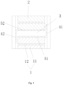
Fig. 1 illustrates a schematic structural diagram ofEmbodiment 1 of a connecting structure according to the present disclosure. -
Fig. 2 illustrates a schematic structural diagram of a size ofEmbodiment 1 of a connecting structure according to the present disclosure. -
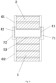
Fig. 3 illustrates a schematic structural diagram ofEmbodiment 2 of a connecting structure according to the present disclosure. -
Fig. 4 illustrates a schematic structural diagram of Embodiment 4 of a connecting structure according to the present disclosure. -
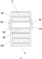
Fig. 5 illustrates a schematic structural diagram ofEmbodiment 3 of a connecting structure according to the present disclosure. -
Fig. 6 illustrates a schematic structural diagram of a first heat exchange body and a second heat exchange body of a connecting structure according to the present disclosure. -
Fig. 7 illustrates a schematic structural diagram of a heat exchanger of a connecting structure according to the present disclosure. - Herein, the above drawings include the following reference signs.
1. First heat exchange body; 11. Connecting fin; 12. Connecting pipe; 2. Second heat exchange body; 3. Connecting gap; 41. First baffle; 42. Second baffle; 43. Third baffle; 44. Fourth baffle; 51. First connecting plate; 52. Second connecting plate; 53. Third connecting plate; 61. First header; 62. Second header; 71. First connecting piece; 72. Second connecting piece. - It is to be noted that the embodiments in the present disclosure and features in the embodiments may be combined with each other without conflict. The present disclosure is described in detail below with reference to the drawings and in conjunction with the embodiments.
- Referring to
Fig. 1 to Fig. 7 , a connecting structure of the embodiment includes: a firstheat exchange body 1 and a secondheat exchange body 2 which are configured to transfer heat, the firstheat exchange body 1 and the secondheat exchange body 2 being connected with each other, and a connectinggap 3 being provided between the firstheat exchange body 1 and the secondheat exchange body 2; and afirst baffle 41 and asecond baffle 42, thefirst baffle 41 and thesecond baffle 42 being respectively located on two opposite sides of the firstheat exchange body 1 and the secondheat exchange body 2, thefirst baffle 41 and thesecond baffle 42 being oppositely disposed, and the connectinggap 3 being located between thefirst baffle 41 and thesecond baffle 42. By adopting the above arrangement, thefirst baffle 41 and thesecond baffle 42 are disposed on both sides of the firstheat exchange body 1 and the secondheat exchange body 2, so that the wind blocking effect can be achieved, and the airflow is prevented from flowing through the connectinggap 3, so that there is no need to use the manual wrapping manner, the heat exchange efficiency of the heat exchanger is improved, and the problem in the related art of low efficiency of splicing operation of the heat exchanger is solved. - Specifically, since the first
heat exchange body 1 and the secondheat exchange body 2 are not installed closely on one side, wind flows on both sides, and if it is only on one side, the wind protection effect is not great. Therefore, the baffles are disposed on both sides, that is, thefirst baffle 41 and thesecond baffle 42 are disposed, which can effectively reduce the flow of wind. - In the connecting structure of the embodiment, referring to
Fig. 1 to Fig. 5 , the connecting structure further includes: a first connectingplate 51, the first connectingplate 51 being connected to the firstheat exchange body 1, and thefirst baffle 41 being connected to the first connectingplate 51; and/or, a second connectingplate 52, the second connectingplate 52 being connected to the secondheat exchange body 2, and thesecond baffle 42 being connected to the second connectingplate 52. - Specifically, the structure of a side plate on one side of a single product that needs to be spliced is changed to an L-shaped side plate, and two products that need to be spliced are assembled in an L- shape for mirror assembly. The spliced L-shaped side plates on both sides can effectively protect the gap and block the wind. This solution is applicable to, but not limited to, double-piece splicing.
- Referring to
Fig. 2 , in the connecting structure of the embodiment, the connecting structure further includes: the first connectingplate 51 and the second connectingplate 52 which are arranged parallel to each other; and/or, the first connectingplate 51 and thefirst baffle 41 which are arranged perpendicular to each other; and/or, the second connectingplate 52 and thesecond baffle 42 which are arranged perpendicular to each other. Specifically, the first connectingplate 51 and the second connectingplate 52 are disposed at one end of a fin and are fixedly connected with an end of the fin, so as to effectively prevent the fin from being inverted. - It is to be noted that a specific arrangement of the connecting plate and the baffle is not limited. The first connecting
plate 51 and thefirst baffle 41, as well as the second connectingplate 52 and thesecond baffle 42 are connected through connecting pieces, or the first connectingplate 51 and thefirst baffle 41, as well as the second connectingplate 52 and thesecond baffle 42 are disposed integrally. - In the connecting structure of the embodiment, referring to
Fig. 2 , the firstheat exchange body 1 includes a plurality of connectingfins 11 and a plurality of connectingpipes 12, the plurality of connectingfins 11 and the plurality of connectingpipes 12 being connected to each other in a staggered manner in a first direction. A length of the first connectingplate 51 is L1, and an outer diameter of the connectingpipe 12 is W, where L1≥1.1W, thereby ensuring that a vertical side plate has a certain distance from the fin and a flat tube, and effectively preventing the first baffle or the second baffle from colliding with the flat tube and the fin during splicing if they are too close. - Referring to
Fig. 2 , in the connecting structure of the embodiment, a length of thefirst baffle 41 is L2, and a thickness of the connectingfin 11 in the first direction is H, where L2≥0.95(1.5H+T2). Therefore, it is ensured that an end of the baffle is higher than half a height of the fin, so that the baffle has a better wind blocking effect. - In the connecting structure of the embodiment, referring to
Fig. 1 to Fig. 5 , a thickness of the connectingpipe 12 in the first direction is T1, and a thickness of thefirst baffle 41 and thesecond baffle 42 are T2, where T1≤T2≤2T1. The arrangement of the thickness of the baffle effectively ensures the strength of the baffle. - Referring to
Fig. 1 to Fig. 7 , in the connecting structure of the embodiment, the connecting structure includes a third connectingplate 53, the third connectingplate 53 is connected with the firstheat exchange body 1, and thefirst baffle 41 and thesecond baffle 42 being respectively connected with both ends of the third connectingplate 53. - In the connecting structure of the embodiment, referring to
Fig. 5 , the connecting structure further includes athird baffle 43 and afourth baffle 44 which are spaced apart from each other, thethird baffle 43 and thefourth baffle 44 are both connected with the secondheat exchange body 2, and thethird baffle 43 and thefourth baffle 44 are located between thefirst baffle 41 and thesecond baffle 42, so that the double-layer baffles are disposed on two opposite sides of the connecting gap to enhance the wind blocking effect. - Referring to
Fig. 1 to Fig. 7 , in the connecting structure of the embodiment, the connecting structure further includes: afirst header 61, thefirst header 61 being connected with the firstheat exchange body 1; asecond header 62, thesecond header 62 being connected with the secondheat exchange body 2. Thefirst header 61 is provided with a first connectingpiece 71 for connected with thesecond header 62; and, thesecond header 62 is provided with a second connectingpiece 72 for connected with thefirst header 61. - In order to evenly distribute a refrigerant inside the header to the connecting pipe, the heat exchange efficiency is improved. Specifically, in some embodiments, the
first header 61 is connected with the firstheat exchange body 1; thesecond header 62 is connected with the secondheat exchange body 2; thefirst header 61 is provided with the first connectingpiece 71; and thesecond header 62 is provided with the second connectingpiece 72. The first connectingpiece 71 is connected with the second connectingpiece 72, so that thefirst header 61 and thesecond header 62 are connected, thereby completing the connection between the firstheat exchange body 1 and the secondheat exchange body 2. In this way, the connection between the firstheat exchange body 1 and the secondheat exchange body 2 is firmer. - Referring to
Fig. 1 , in some embodiments, thefirst baffle 41 and thesecond baffle 42 are respectively connected with the firstheat exchange body 1 and the secondheat exchange body 2, and thefirst baffle 41 and thesecond baffle 42 are of L-shaped structures and are symmetrically disposed. - Referring to
Fig. 3 , in some embodiments, thefirst baffle 41 and thesecond baffle 42 are both connected with the firstheat exchange body 1, thefirst baffle 41 and thesecond baffle 42 are of an integrated structure and are U-shaped, and thefirst baffle 41 and thesecond baffle 42 are symmetrically disposed. - Referring to
Fig. 5 , in some embodiments, thefirst baffle 41 and thesecond baffle 42 are both connected with the firstheat exchange body 1, thefirst baffle 41 and thesecond baffle 42 are of an integrated structure and are U-shaped, and thefirst baffle 41 and thesecond baffle 42 are asymmetrically disposed, that is, thefirst baffle 41 and thesecond baffle 42 have different lengths. - Referring to
Fig. 4 , in some embodiments, the connecting structure further includes athird baffle 43 and afourth baffle 44 which are spaced apart from each other, thethird baffle 43 and thefourth baffle 44 are both connected with the secondheat exchange body 2, and thethird baffle 43 and thefourth baffle 44 are located between thefirst baffle 41 and thesecond baffle 42. - A heat exchanger of the embodiment includes a connecting structure, the connecting structure being the above connecting structure.
- From the above description, it is seen that the above embodiments of the present disclosure achieve the following technical effects.
- The connecting structure of the embodiment includes: the first
heat exchange body 1 and the secondheat exchange body 2 which are configured to transfer heat, the firstheat exchange body 1 and the secondheat exchange body 2 being connected with each other, and the connectinggap 3 being provided between the firstheat exchange body 1 and the secondheat exchange body 2; and thefirst baffle 41 and thesecond baffle 42, thefirst baffle 41 and thesecond baffle 42 being respectively located on two opposite sides of the firstheat exchange body 1 and the secondheat exchange body 2, thefirst baffle 41 and thesecond baffle 42 being oppositely disposed, and the connectinggap 3 being located between thefirst baffle 41 and thesecond baffle 42. By adopting the above arrangement, thefirst baffle 41 and thesecond baffle 42 are disposed on both sides of the firstheat exchange body 1 and the secondheat exchange body 2, so that the wind blocking effect can be achieved, and the airflow is prevented from flowing through the connectinggap 3, so that there is no need to use the manual wrapping manner, the heat exchange efficiency of the heat exchanger is improved, and the problem in the related art of low efficiency of the splicing operation of the heat exchanger is solved. - It is to be noted that terms used herein are only for the purpose of describing the specific implementations and not intended to limit exemplary implementations of the present disclosure. For example, singular forms, used herein, are also intended to include plural forms, unless otherwise clearly pointed out. In addition, it is also to be understood that terms "contain" and/or "include" used in the specification refer/refers to existence of features, steps, operations, apparatuses, components and/or combinations thereof.
- Unless otherwise specified, relative arrangements of components and steps elaborated in these embodiments, numeric expressions and numeric values do not limit the scope of the present disclosure. Furthermore, it is to be understood that for ease of descriptions, the size of each part shown in the drawings is not drawn in accordance with an actual proportional relation. Technologies, methods and devices known by those of ordinary skill in the art may not be discussed in detail. However, where appropriate, the technologies, the methods and the devices shall be regarded as split of the authorized description. In all examples shown and discussed herein, any specific value should be interpreted as only exemplar values instead of limited values. As a result, other examples of the exemplary embodiments may have different values. It is to be noted that similar marks and letters represent similar items in the following drawings. As a result, once a certain item is defined in one drawing, it is unnecessary to further discus the certain item in the subsequent drawings.
- In the description of the present disclosure, it is to be understood that the orientations or positional relationships indicated by the orientation words "front, rear, upper, down, left and right", "transverse, longitudinal, vertical and horizontal", "top and bottom", etc. are based on the orientations or positional relationships shown in the drawings, and are only for the convenience of describing the present disclosure and simplifying the description. Unless stated to the contrary, these orientation words do not indicate or imply that the apparatus or element referred to must have a specific orientation, be constructed and operated in a specific orientation, and therefore cannot be construed as limiting the scope of protection of the present disclosure. The orientation words "inside and outside" refer to inside and outside relative to the outline of each part itself.
- For ease of description, spatially relative terms such as "over", "above", "on an upper surface" and "upper" may be used herein for describing a spatial position relation between a device or feature and other devices or features shown in the drawings. It should be understood that the spatially relative terms are intended to contain different orientations of the device in usage or operation besides the orientations of the devices described in the drawings. For example, if the devices in the drawings are inverted, those described as "above other devices or structures" or "over other devices or structures" will then be positioned as "below other devices or structures" or "under other devices or structures". Thus, the exemplary term "above" may include both "above" and "below" orientations. The device may also be positioned in various other ways (rotated 90 degrees or at other orientations) and the spatially relative descriptions used herein are interpreted accordingly.
- Furthermore, it is to be noted that the use of the words "first", "second" and the like to define parts is only for the convenience of distinguishing the corresponding parts, unless otherwise stated, the words have no special meaning, and therefore cannot be construed as limiting the scope of protection of the present disclosure.
- The above is only the preferred embodiments of the present disclosure, and is not intended to limit the present disclosure, and for those of ordinary skill in the art, various modifications and changes may be made to the present disclosure. Any modifications, equivalent substitutions, improvements, etc. within the spirit and scope of the present disclosure shall be included in the scope of protection of the present disclosure.
Claims (10)
- A connecting structure, comprising:a first heat exchange body (1) and a second heat exchange body (2) which are configured to transfer heat, the first heat exchange body (1) and the second heat exchange body (2) are connected with each other, and a connecting gap (3) being provided between the first heat exchange body (1) and the second heat exchange body (2); anda first baffle (41) and a second baffle (42), the first baffle (41) and the second baffle (42) being respectively located on two opposite sides of the first heat exchange body (1) and the second heat exchange body (2), the first baffle (41) and the second baffle (42) being oppositely disposed, and the connecting gap (3) being located between the first baffle (41) and the second baffle (42).
- The connecting structure according to claim 1, further comprising:a first connecting plate (51), the first connecting plate (51) being connected with the first heat exchange body (1), and the first baffle (41) being connected with the first connecting plate (51); and/or,a second connecting plate (52), the second connecting plate (52) being connected with the second heat exchange body (2), and the second baffle (42) being connected with the second connecting plate (52).
- The connecting structure according to claim 2, further comprising:the first connecting plate (51) and the second connecting plate (52) which are disposed parallel to each other; and/or,the first connecting plate (51) and the first baffle (41) which are disposed perpendicular to each other; and/or,the second connecting plate (52) and the second baffle (42) which are disposed perpendicular to each other.
- The connecting structure according to claim 2, wherein the first heat exchange body (1) comprises a plurality of connecting fins (11) and a plurality of connecting pipes (12), the plurality of connecting fins (11) and the plurality of connecting pipes (12) being connected to each other in a staggered manner in a first direction, wherein a length of the first connecting plate (51) is L1, and an outer diameter of the connecting pipe (12) is W, where L1≥1.1 W.
- The connecting structure according to claim 4, wherein a length of the first baffle (41) is L2, and a thickness of the connecting fin (11) in the first direction is H, where L2≥0.95(1.5H+T2).
- The connecting structure according to claim 4, wherein a thickness of the connecting pipe (12) in the first direction is T1, and a thickness of the first baffle (41) and/or the second baffle (42) is T2, where T1≤T2≤2T1.
- The connecting structure according to claim 1, wherein the connecting structure comprises a third connecting plate (53), the third connecting plate (53) is connected with the first heat exchange body (1), and the first baffle (41) and the second baffle (42)are respectively connected with both ends of the third connecting plate (53).
- The connecting structure according to claim 7, wherein further comprising a third baffle (43) and a fourth baffle (44) which are spaced apart from each other, the third baffle (43) and the fourth baffle (44) are both connected with the second heat exchange body (2), and the third baffle (43) and the fourth baffle (44) are located between the first baffle (41) and the second baffle (42).
- The connecting structure according to any one of claims 1 to 8, further comprising:a first header (61), the first header (61) is connected with the first heat exchange body (1);a second first header (62), the second header (62) is connected with the second heat exchange body (2);wherein the first header (61) is provided with a first connecting piece (71) for connected with the second header (62); and/or, the second header (62) is provided with a second connecting piece (72) for connected with the first header (61).
- A heat exchanger, comprising a connecting structure, wherein the connecting structure is the connecting structure according to any one of claims 1 to 9.
Applications Claiming Priority (2)
| Application Number | Priority Date | Filing Date | Title |
|---|---|---|---|
| CN202221217630.0U CN217403249U (en) | 2022-05-20 | 2022-05-20 | Connection structure and heat exchanger with same |
| PCT/CN2023/095113 WO2023222096A1 (en) | 2022-05-20 | 2023-05-18 | Connecting structure and heat exchanger having same |
Publications (2)
| Publication Number | Publication Date |
|---|---|
| EP4517248A1 true EP4517248A1 (en) | 2025-03-05 |
| EP4517248A4 EP4517248A4 (en) | 2025-08-20 |
Family
ID=83144627
Family Applications (1)
| Application Number | Title | Priority Date | Filing Date |
|---|---|---|---|
| EP23807046.0A Pending EP4517248A4 (en) | 2022-05-20 | 2023-05-18 | CONNECTION STRUCTURE AND HEAT EXCHANGER |
Country Status (4)
| Country | Link |
|---|---|
| US (1) | US20250327626A1 (en) |
| EP (1) | EP4517248A4 (en) |
| CN (1) | CN217403249U (en) |
| WO (1) | WO2023222096A1 (en) |
Families Citing this family (1)
| Publication number | Priority date | Publication date | Assignee | Title |
|---|---|---|---|---|
| CN217403249U (en) * | 2022-05-20 | 2022-09-09 | 浙江盾安热工科技有限公司 | Connection structure and heat exchanger with same |
Family Cites Families (10)
| Publication number | Priority date | Publication date | Assignee | Title |
|---|---|---|---|---|
| NL130632C (en) * | 1965-03-12 | |||
| US4651816A (en) * | 1986-03-19 | 1987-03-24 | Modine Manufacturing Company | Heat exchanger module for a vehicle or the like |
| JPH0826963B2 (en) * | 1990-09-17 | 1996-03-21 | 株式会社東芝 | Exhaust heat recovery boiler |
| JPH10160382A (en) * | 1996-11-29 | 1998-06-19 | Toyo Radiator Co Ltd | Heat exchanger for air conditioning and manufacture of the same |
| EP1571325B1 (en) * | 1998-04-15 | 2016-03-09 | Phillips & Temro Industries Inc. | Modular air intake heater |
| JP2001317893A (en) * | 2000-05-02 | 2001-11-16 | Mitsubishi Heavy Ind Ltd | Gas short circuit pass preventive baffle |
| KR102095755B1 (en) * | 2018-06-14 | 2020-04-01 | 주식회사 조은바람 | Absorption pad assembly for air cooling |
| CN112747502A (en) * | 2019-10-29 | 2021-05-04 | 浙江盾安热工科技有限公司 | Heat exchanger |
| CN213599858U (en) * | 2020-11-05 | 2021-07-02 | 深圳智焓热传科技有限公司 | Heat exchange core and heat exchanger |
| CN217403249U (en) * | 2022-05-20 | 2022-09-09 | 浙江盾安热工科技有限公司 | Connection structure and heat exchanger with same |
-
2022
- 2022-05-20 CN CN202221217630.0U patent/CN217403249U/en active Active
-
2023
- 2023-05-18 WO PCT/CN2023/095113 patent/WO2023222096A1/en not_active Ceased
- 2023-05-18 EP EP23807046.0A patent/EP4517248A4/en active Pending
- 2023-05-18 US US18/867,753 patent/US20250327626A1/en active Pending
Also Published As
| Publication number | Publication date |
|---|---|
| WO2023222096A1 (en) | 2023-11-23 |
| CN217403249U (en) | 2022-09-09 |
| US20250327626A1 (en) | 2025-10-23 |
| EP4517248A4 (en) | 2025-08-20 |
Similar Documents
| Publication | Publication Date | Title |
|---|---|---|
| US9134070B2 (en) | Radiator and electronic apparatus including same | |
| CN107401939A (en) | Heat-exchange device | |
| CN103069245A (en) | Heat exchanger and refrigeration and air conditioning device | |
| US11874066B2 (en) | Micro-channel heat exchanger | |
| EP4517248A1 (en) | Connecting structure and heat exchanger having same | |
| CN101788235B (en) | Heat exchanger | |
| EP4354072A1 (en) | Connecting joint tube and heat exchanger having same | |
| US20240255232A1 (en) | Heat Exchanger | |
| WO2023174167A1 (en) | Heat exchanger and air conditioning system comprising same | |
| CN117190743B (en) | Adjustable radiator and method of using the same | |
| CN110530190A (en) | Header and heat exchanger | |
| CN107014231A (en) | A kind of plate-type heat recovery device | |
| CN116412713A (en) | A three-dimensional variable cross-section airfoil fin heat exchange plate and core structure | |
| CN207317318U (en) | Heat exchange module, heat exchanger and refrigerator | |
| CN212658085U (en) | Heat exchanger | |
| CN204574913U (en) | A kind of heat exchanger traverse baffle eliminating heat transfer dead band | |
| US11624564B2 (en) | Heat exchanger assembly | |
| EP4170272A1 (en) | Heat exchanger flat tube and heat exchanger having same | |
| CN212390891U (en) | Flat heat exchange tube and heat exchanger with same | |
| CN212340018U (en) | Indirect air cooling radiator tube bundle | |
| CN212390890U (en) | Flat heat exchange tube, heat exchanger and air conditioner | |
| ITTO990194A1 (en) | MULTI-FLOW HEAT EXCHANGER WITH INLET AND OUTLET DUCTS REFRIGERATED INTERCONNECTED BY STEPS OF A PLATE TUBE. | |
| CN201191149Y (en) | Movement device for heat exchanger | |
| CN207365781U (en) | A kind of flat pipes of heat exchanger | |
| CN108941816B (en) | Heat exchanger processing device and heat exchanger processing method |
Legal Events
| Date | Code | Title | Description |
|---|---|---|---|
| STAA | Information on the status of an ep patent application or granted ep patent |
Free format text: STATUS: THE INTERNATIONAL PUBLICATION HAS BEEN MADE |
|
| PUAI | Public reference made under article 153(3) epc to a published international application that has entered the european phase |
Free format text: ORIGINAL CODE: 0009012 |
|
| STAA | Information on the status of an ep patent application or granted ep patent |
Free format text: STATUS: REQUEST FOR EXAMINATION WAS MADE |
|
| 17P | Request for examination filed |
Effective date: 20241129 |
|
| AK | Designated contracting states |
Kind code of ref document: A1 Designated state(s): AL AT BE BG CH CY CZ DE DK EE ES FI FR GB GR HR HU IE IS IT LI LT LU LV MC ME MK MT NL NO PL PT RO RS SE SI SK SM TR |
|
| A4 | Supplementary search report drawn up and despatched |
Effective date: 20250723 |
|
| RIC1 | Information provided on ipc code assigned before grant |
Ipc: F28F 9/26 20060101AFI20250717BHEP Ipc: F28D 1/053 20060101ALI20250717BHEP Ipc: F28F 9/013 20060101ALI20250717BHEP Ipc: F28F 9/00 20060101ALI20250717BHEP |
|
| DAV | Request for validation of the european patent (deleted) | ||
| DAX | Request for extension of the european patent (deleted) | ||
| RIC1 | Information provided on ipc code assigned before grant |
Ipc: F28F 9/26 20060101AFI20260305BHEP Ipc: F28D 1/053 20060101ALI20260305BHEP Ipc: F28F 9/013 20060101ALI20260305BHEP Ipc: F28F 9/00 20060101ALI20260305BHEP |
|
| GRAP | Despatch of communication of intention to grant a patent |
Free format text: ORIGINAL CODE: EPIDOSNIGR1 |
|
| STAA | Information on the status of an ep patent application or granted ep patent |
Free format text: STATUS: GRANT OF PATENT IS INTENDED |