EP4517240A1 - Electrode material firing system - Google Patents
Electrode material firing system Download PDFInfo
- Publication number
- EP4517240A1 EP4517240A1 EP23820121.4A EP23820121A EP4517240A1 EP 4517240 A1 EP4517240 A1 EP 4517240A1 EP 23820121 A EP23820121 A EP 23820121A EP 4517240 A1 EP4517240 A1 EP 4517240A1
- Authority
- EP
- European Patent Office
- Prior art keywords
- electrode material
- supply tube
- tube
- heating
- sintering system
- Prior art date
- Legal status (The legal status is an assumption and is not a legal conclusion. Google has not performed a legal analysis and makes no representation as to the accuracy of the status listed.)
- Pending
Links
Images

Classifications
-
- H—ELECTRICITY
- H01—ELECTRIC ELEMENTS
- H01M—PROCESSES OR MEANS, e.g. BATTERIES, FOR THE DIRECT CONVERSION OF CHEMICAL ENERGY INTO ELECTRICAL ENERGY
- H01M4/00—Electrodes
- H01M4/02—Electrodes composed of, or comprising, active material
- H01M4/04—Processes of manufacture in general
-
- F—MECHANICAL ENGINEERING; LIGHTING; HEATING; WEAPONS; BLASTING
- F27—FURNACES; KILNS; OVENS; RETORTS
- F27B—FURNACES, KILNS, OVENS OR RETORTS IN GENERAL; OPEN SINTERING OR LIKE APPARATUS
- F27B7/00—Rotary-drum furnaces, i.e. horizontal or slightly inclined
- F27B7/10—Rotary-drum furnaces, i.e. horizontal or slightly inclined internally heated, e.g. by means of passages in the wall
-
- F—MECHANICAL ENGINEERING; LIGHTING; HEATING; WEAPONS; BLASTING
- F27—FURNACES; KILNS; OVENS; RETORTS
- F27B—FURNACES, KILNS, OVENS OR RETORTS IN GENERAL; OPEN SINTERING OR LIKE APPARATUS
- F27B7/00—Rotary-drum furnaces, i.e. horizontal or slightly inclined
- F27B7/20—Details, accessories or equipment specially adapted for rotary-drum furnaces
- F27B7/22—Rotary drums; Supports therefor
-
- F—MECHANICAL ENGINEERING; LIGHTING; HEATING; WEAPONS; BLASTING
- F27—FURNACES; KILNS; OVENS; RETORTS
- F27B—FURNACES, KILNS, OVENS OR RETORTS IN GENERAL; OPEN SINTERING OR LIKE APPARATUS
- F27B7/00—Rotary-drum furnaces, i.e. horizontal or slightly inclined
- F27B7/20—Details, accessories or equipment specially adapted for rotary-drum furnaces
- F27B7/32—Arrangement of devices for charging
-
- F—MECHANICAL ENGINEERING; LIGHTING; HEATING; WEAPONS; BLASTING
- F27—FURNACES; KILNS; OVENS; RETORTS
- F27B—FURNACES, KILNS, OVENS OR RETORTS IN GENERAL; OPEN SINTERING OR LIKE APPARATUS
- F27B7/00—Rotary-drum furnaces, i.e. horizontal or slightly inclined
- F27B7/20—Details, accessories or equipment specially adapted for rotary-drum furnaces
- F27B7/32—Arrangement of devices for charging
- F27B7/3205—Charging
-
- F—MECHANICAL ENGINEERING; LIGHTING; HEATING; WEAPONS; BLASTING
- F27—FURNACES; KILNS; OVENS; RETORTS
- F27D—DETAILS OR ACCESSORIES OF FURNACES, KILNS, OVENS OR RETORTS, IN SO FAR AS THEY ARE OF KINDS OCCURRING IN MORE THAN ONE KIND OF FURNACE
- F27D11/00—Arrangement of elements for electric heating in or on furnaces
- F27D11/02—Ohmic resistance heating
- F27D11/04—Ohmic resistance heating with direct passage of current through the material being heated
-
- F—MECHANICAL ENGINEERING; LIGHTING; HEATING; WEAPONS; BLASTING
- F27—FURNACES; KILNS; OVENS; RETORTS
- F27D—DETAILS OR ACCESSORIES OF FURNACES, KILNS, OVENS OR RETORTS, IN SO FAR AS THEY ARE OF KINDS OCCURRING IN MORE THAN ONE KIND OF FURNACE
- F27D3/00—Charging; Discharging; Manipulation of charge
- F27D3/08—Screw feeders; Screw dischargers
-
- H—ELECTRICITY
- H01—ELECTRIC ELEMENTS
- H01M—PROCESSES OR MEANS, e.g. BATTERIES, FOR THE DIRECT CONVERSION OF CHEMICAL ENERGY INTO ELECTRICAL ENERGY
- H01M4/00—Electrodes
- H01M4/02—Electrodes composed of, or comprising, active material
- H01M4/04—Processes of manufacture in general
- H01M4/0471—Processes of manufacture in general involving thermal treatment, e.g. firing, sintering, backing particulate active material, thermal decomposition, pyrolysis
-
- H—ELECTRICITY
- H01—ELECTRIC ELEMENTS
- H01M—PROCESSES OR MEANS, e.g. BATTERIES, FOR THE DIRECT CONVERSION OF CHEMICAL ENERGY INTO ELECTRICAL ENERGY
- H01M4/00—Electrodes
- H01M4/02—Electrodes composed of, or comprising, active material
- H01M4/36—Selection of substances as active materials, active masses, active liquids
-
- Y—GENERAL TAGGING OF NEW TECHNOLOGICAL DEVELOPMENTS; GENERAL TAGGING OF CROSS-SECTIONAL TECHNOLOGIES SPANNING OVER SEVERAL SECTIONS OF THE IPC; TECHNICAL SUBJECTS COVERED BY FORMER USPC CROSS-REFERENCE ART COLLECTIONS [XRACs] AND DIGESTS
- Y02—TECHNOLOGIES OR APPLICATIONS FOR MITIGATION OR ADAPTATION AGAINST CLIMATE CHANGE
- Y02E—REDUCTION OF GREENHOUSE GAS [GHG] EMISSIONS, RELATED TO ENERGY GENERATION, TRANSMISSION OR DISTRIBUTION
- Y02E60/00—Enabling technologies; Technologies with a potential or indirect contribution to GHG emissions mitigation
- Y02E60/10—Energy storage using batteries
Definitions
- the present invention relates to an electrode material sintering system.
- Secondary batteries are rechargeable unlike primarily batteries, and also, the possibility of compact size and high capacity is high. Thus, recently, many studies on secondary batteries are being carried out. As technology development and demands for mobile devices increase, the demands for secondary batteries as energy sources are rapidly increasing.
- Rechargeable batteries are classified into coin type batteries, cylindrical type batteries, prismatic type batteries, and pouch type batteries according to a shape of a battery case.
- an electrode assembly mounted in a battery case is a chargeable and dischargeable power generating device having a structure in which an electrode and a separator are stacked.
- Secondary batteries are attracting much attention as energy sources for power devices such as electric bicycle, electric vehicles, and hybrid electric vehicles as well as mobile devices such as mobile phones, digital cameras, and laptops.
- lithium transition metal oxide is used as a positive electrode active material. That is, lithium cobalt oxide having a high operating voltage and excellent capacity characteristics, lithium nickel oxide having a high reversible capacity of about 200 mAh/g and easy implementation of large-capacity batteries, lithium nickel cobalt oxide in which a portion of nickel is substituted with cobalt, lithium nickel cobalt metal oxide in which a portion of nickel is substituted with manganese, cobalt or aluminum, low-cost lithium manganese oxide having excellent thermal stability, lithium iron phosphate having excellent stability, and the like are being used as the positive electrode active material.
- the positive electrode active material is prepared by mixing a precursor for producing the positive electrode active material with the lithium raw material and then putting the mixture into an electrode material sintering system to perform sintering at a high temperature.
- the electrode material supply device that supplies an electrode material has a simple structure constituted by a screw and a supply tube that is a case surrounding the screw to move the raw material for the electrode material.
- the electrode material sintering system is configured as a structure in which an end of the supply tube is disposed inside a main tube that heats and sinters the raw material to supply the raw material for the electrode material into the main tube.
- the raw material containing moisture generated by thermal decomposition generates stress inside the supply tube to cause a problem in that durability of an equipment is deteriorated.
- One aspect of the present invention is to provide an electrode material sintering system capable of preventing undesired additional thermal reaction from occurring.
- An electrode material sintering system may include: an electrode material sintering device configured to sinter a raw material for an electrode material; and an electrode material supply device configured to supply the raw material for the electrode material to the electrode material sintering device, wherein the electrode material supply device includes: a supply tube in which an inner space, into which the raw material for the electrode material is accommodated to move, is defined; a cooling part configured to cool the inner space of the supply tube; and a heating part configured to heat the outside of the supply tube.
- the cooling part that cools the inner space of the supply tube through which the raw material for the electrode material moves may be provided to prevent the undesired additional thermal reaction from occurring.
- the heating part for heating the outside of the supply tube may be provided to prevent the vapor generated by the thermal reaction from being condensed at the outside of the supply tube and then being mixed again with the raw material or prevent the feeding from being interrupted by blocking the outlet of the supply tube.
- the insulating part may be disposed between the cooling part and the heating part to block the heat transfer between the cooling part and the heating part, and thus, the respective functions of the cooling part and the heating part may be effectively performed.
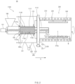
- FIG. 1 is a schematic cross-sectional view of an electrode material sintering system according to a first embodiment of the present invention.
- a rotating part 230 illustrated in FIG. 1 is not cross-sectioned for convenience of description.
- an electrode material sintering system 10 includes an electrode material sintering device 200 that sinters a raw material M for an electrode material, and an electrode material supply device 100 that supplies the raw material M for the electrode material to the electrode material sintering device 200.
- the electrode material sintering system 10 according to the first embodiment of the present invention may further include a chamber 300 that collects a gas and water vapor discharged from a heating tube 210.
- the electrode material supply device 100 may include a supply tube 110 through which the raw material M for the electrode material moves, a cooling part 120, a heating part 140, an insulating part 130, a screw 150, a blocking part 170, and a supply hopper 180.
- the electrode material sintering device 200 may include a heating tube 210 through which the raw material for the electrode material moves from the supply tube 110, a heater 220, a rotating part 230, and a baffle 240.
- the supply tube 110 may have an inner space 110a in which the raw material M for the electrode material is accommodated to move.
- the raw material M for the electrode material may be, for example, a raw material for a positive electrode material.
- the supply tube 110 may be provided in a tubular shape.
- the supply tube 110 may be provided in, for example, a cylindrical tubular shape.
- the supply tube 110 may include a first portion 111 disposed outside the heating tube 210 and a second portion 112 disposed inside the heating tube 210.
- the heating part 140 and the cooling part 120 may be installed at the first portion 111 and the second portion 112 of the supply tube 110. That is, the heating part 140 and the cooling part 120 may be installed at portions disposed inside and outside the heating tube 210 in the supply tube 110.
- the cooling part 120 may cool the inner space 110a of the supply tube 110.
- the cooling part 120 may include a cooling line 121 through which a coolant fluid moves and of which surrounding is maintained below a certain temperature.
- the raw material M for the electrode material may include lithium hydroxide
- the cooling part 120 may cool the inner space 110a of the supply tube 110, for example, so that a temperature of the raw material M for the electrode material becomes 10°C to 80°C.
- the cooling part 120 may specifically cool the inner space 110a of the supply tube 110, for example, so that the temperature of the raw material M for the electrode material becomes 10°C to 60°C. Therefore, the cooling part 120 may cool the inner space 110a of the supply tube 110 so that the temperature of the raw material M for the electrode material becomes 60°C or less to prevent additional thermal reaction that is not desired and not controlled on an area except for an reaction area in the process design from occurring, thereby preventing intermediate products from being generated so that an error in process control is prevented from occurring.
- the raw material containing moisture generated by pyrolysis may generate stress in the supply tube 110 to prevent durability of equipment from being deteriorated, and it is effective in preventing an error in quantitative input of the raw material, which is one of important process conditions, from occurring due to a change in powder characteristic (density, viscosity, flow, etc.) of the raw material due to the moisture.
- the cooling part 120 may cool the inner space 110a of the supply tube 110 so that the temperature of the raw material M for the electrode material becomes 10°C or more to prevent the addition thermal reaction or deterioration of the raw material from occurring.
- the cooling line 121 may include a coolant inlet 121a through which a coolant fluid flows and a coolant outlet 121b through which the coolant fluid is discharged.
- the heating part 140 may heat the outside of the supply tube 110.
- the heating part 140 may be provided along the inner surface of the supply tube 110 to heat the supply tube 110 and the outside of the supply tube 110.
- the insulating part 130 may be disposed between the cooling part 120 and the heating part 140 to block the heat transfer between the cooling part 120 and the heating part 140. Thus, each function of the cooling part 120 and the heating part 140 may be sufficiently exhibited.
- the insulating part 130 may be provided along the inner surface of the heating part 140.
- the screw 150 may be disposed in the inner space 110a of the supply tube 110 to allow the raw material M for the electrode material to move.
- the screw 150 may have, for example, a rotating shaft and a spiral wing shape along an outer circumferential surface of the rotating shaft.
- An end of the screw 150 may be connected to a screw motor 151 to rotate through the screw motor 151, and the raw material M for the electrode material disposed in the inner space 110a of the supply tube 110 may move toward the heating tube 210.
- the blocking part 170 may be provided on an outer surface of the supply tube 110, and the condensed vapor disposed on the outer surface of the supply tube 110 may be prevented from moving to the inside of the electrode material sintering device 200 along the outer surface of the supply tube 110.
- the blocking part 170 may be provided as a metal plate provided along the outer circumference of the supply tube 110.
- the blocking part 170 may be provided in a circular plate shape with a hole defined at a central portion thereof, and the hole defined at the central portion may be inserted into the outer surface of the supply tube 110.
- the supply hopper 180 may supply the raw material M for the electrode material to the supply tube 110.
- the supply hopper 180 may be connected to one side of the supply tube 110, and the other side of the supply tube 110 may be disposed inside the heating tube 210.
- the heating tube 210 may define an accommodation space 210a in which the raw material M for the electrode material moves from the supply tube 110 so as to be accommodated.
- the heating tube 210 may be provided in a tubular shape.
- the heating tube 210 may be provided in, for example, a cylindrical tubular shape.
- the heating tube 210 may be provided in a shape having a diameter greater than that of the supply tube 110.
- the heater 220 may heat the heating tube 210 to heat the raw material M for the electrode material disposed in the accommodation space 210a of the heating tube 210.
- the heating tube 210 may rotate by the rotating part 230.
- the rotating part 230 may include a driving gear 231 providing rotational force and a driven gear 232 receiving the rotational force from the driving gear 231.
- a driving gear part may be disposed on an outer circumferential surface of the driving gear 231, and the driving gear 231 may rotate as the rotating shaft of the driving motor rotates.
- the driven gear 232 is disposed along the outer surface of the heating tube 210, and a driven gear part engaged with the driving gear part of the driving gear 231 may be disposed on the outer circumferential surface.
- the baffle 240 may be provided inside the heating tube 210 to induce stirring of the raw material M for the electrode material accommodated in the heating tube 210 when the heating tube 210 rotates.
- the baffle 240 may be installed inside the heating tube 210.
- the baffle 240 may include a horizontal bar provided at a predetermined distance from the inner surface of the heating tube 210.
- the horizontal bar may extend along a longitudinal direction of the heating tube 210.
- the horizontal bar may extend, for example, in a direction parallel to a traveling direction G of the raw material M for the electrode material.
- the chamber 300 may have a space accommodating the first portion 111 of the supply tube 110.
- the chamber 300 may include a cylindrical chamber cover 310 and a chamber hopper 320 disposed below the chamber cover 310.
- the chamber 300 may collect a gas and vapor discharged from the first portion 111 of the heating tube 210.
- the gas and vapor discharged from the outside of the heating tube 210 may be collected into the chamber hopper 320 by the chamber cover 310.
- FIG. 2 is a schematic cross-sectional view of an electrode material sintering system according to a second embodiment of the present invention.
- an electrode material sintering system 20 includes an electrode material sintering device 200 that sinters a raw material M for an electrode material, and an electrode material supply device 1100 that supplies the raw material M for the electrode material to the electrode material sintering device 200.
- the electrode material sintering system 20 according to the second embodiment of the present invention may further include a chamber 300 that collects a gas and water vapor discharged from a heating tube 210.
- the electrode material supply device 1100 may include a supply tube 1110 through which the raw material M for the electrode material moves, a cooling part 1120, a heating part 1140, an insulating part 1130, a screw 150, a blocking part 170, and a supply hopper 180.
- the electrode material sintering device 200 may include a heating tube 210 through which the raw material for the electrode material moves from the supply tube 1110, a heater 220, a rotating part 230, and a baffle 240.
- the electrode material sintering system according to the second embodiment of the present invention has a difference in that the heating part 1140 and the cooling part 1120 are installed only at a first portion 1111. Therefore, in the embodiment of the electrode material sintering system 20 according to the second embodiment, duplicated contents with the electrode material sintering system according to the first embodiment will be omitted or briefly described, and the differences therebetween will be mainly described.
- the supply tube 1110 may have an inner space 1110a in which the raw material M for the electrode material is accommodated to move.
- the supply tube 1110 may be provided in a tubular shape.
- the supply tube 1110 may be provided in, for example, a cylindrical tubular shape.
- the supply tube 1110 may include a first portion 1111 disposed outside the heating tube 210 and a second portion 1112 disposed inside the heating tube 210.
- the heating part 1140 and the cooling part 1120 may be installed at the first portion 1111 of the supply tube 1110. That is, the heating part 1140 and the cooling part 1120 may be installed at a portion disposed outside the heating tube 210 in the supply tube 1110. Thus, the heating part 1140 and the cooling part 1120 may not be installed at a second portion 1112 of the supply tube 1110, which is disposed inside the heating tube 210, to prevent a heating temperature within the heating tube 210 from decreasing, thereby facilitating manufacturing thereof.
- the cooling part 1120 may cool the inner space 1110a of the supply tube 1110.
- the cooling part 1120 may include a cooling line 1121 through which a coolant fluid moves and of which surrounding is maintained below a certain temperature.
- the raw material M for the electrode material may include lithium hydroxide
- the cooling part 1120 may cool the inner space 1110a of the supply tube 1110 so that a temperature of the raw material M for the electrode material becomes 10°C to 60°C.
- the cooling line 1121 may include a coolant inlet 1121a through which a coolant fluid flows and a coolant outlet 1121b through which the coolant fluid is discharged.
- the cooling part 1120 may be provided along an inner surface of the insulating part 1130.
- the heating part 1140 may heat the outside of the supply tube 1110.
- the heating part 1140 may heat the outside of the supply tube 1110 to a temperature of 100°C to 150°C.
- the heating part 1140 may be provided along the inner surface of the supply tube 1110 to heat the supply tube 1110 and the outside of the supply tube 1110.
- the insulating part 1130 may be disposed between the cooling part 1120 and the heating part 1140 to block the heat transfer between the cooling part 1120 and the heating part 1140.
- the insulating part 1130 may be provided along the inner surface of the heating part 1140.
- the screw 150 may be disposed in the inner space 1110a of the supply tube 1110 to allow the raw material M for the electrode material to move.
Landscapes
- Engineering & Computer Science (AREA)
- Mechanical Engineering (AREA)
- General Engineering & Computer Science (AREA)
- Chemical & Material Sciences (AREA)
- Chemical Kinetics & Catalysis (AREA)
- Electrochemistry (AREA)
- General Chemical & Material Sciences (AREA)
- Manufacturing & Machinery (AREA)
- Battery Electrode And Active Subsutance (AREA)
- Furnace Charging Or Discharging (AREA)
- Muffle Furnaces And Rotary Kilns (AREA)
Abstract
Description
- The present application claims the benefit of the priority of
Korean Patent Application No. 10-2022-0070534, filed on June 10, 2022 - The present invention relates to an electrode material sintering system.
- Secondary batteries are rechargeable unlike primarily batteries, and also, the possibility of compact size and high capacity is high. Thus, recently, many studies on secondary batteries are being carried out. As technology development and demands for mobile devices increase, the demands for secondary batteries as energy sources are rapidly increasing.
- Rechargeable batteries are classified into coin type batteries, cylindrical type batteries, prismatic type batteries, and pouch type batteries according to a shape of a battery case. In such a secondary battery, an electrode assembly mounted in a battery case is a chargeable and dischargeable power generating device having a structure in which an electrode and a separator are stacked.
- Secondary batteries are attracting much attention as energy sources for power devices such as electric bicycle, electric vehicles, and hybrid electric vehicles as well as mobile devices such as mobile phones, digital cameras, and laptops.
- In the lithium secondary battery, lithium transition metal oxide is used as a positive electrode active material. That is, lithium cobalt oxide having a high operating voltage and excellent capacity characteristics, lithium nickel oxide having a high reversible capacity of about 200 mAh/g and easy implementation of large-capacity batteries, lithium nickel cobalt oxide in which a portion of nickel is substituted with cobalt, lithium nickel cobalt metal oxide in which a portion of nickel is substituted with manganese, cobalt or aluminum, low-cost lithium manganese oxide having excellent thermal stability, lithium iron phosphate having excellent stability, and the like are being used as the positive electrode active material.
- The positive electrode active material is prepared by mixing a precursor for producing the positive electrode active material with the lithium raw material and then putting the mixture into an electrode material sintering system to perform sintering at a high temperature.
- In the conventional electrode material sintering system in which a raw material for the electrode material is sintered by applying heat, the electrode material supply device that supplies an electrode material has a simple structure constituted by a screw and a supply tube that is a case surrounding the screw to move the raw material for the electrode material. In addition, the electrode material sintering system is configured as a structure in which an end of the supply tube is disposed inside a main tube that heats and sinters the raw material to supply the raw material for the electrode material into the main tube.
- However, there is a problem that the raw material input by heat conduction from the inside of the main tube is heated from a portion of the end of the supply tube.
- As a result, the raw material containing moisture generated by thermal decomposition generates stress inside the supply tube to cause a problem in that durability of an equipment is deteriorated.
- In addition, as a result, there is a problem that an error occurring in quantitative input of the raw material that is one of important process conditions due to a change in power characteristic (density, viscosity, flow, etc.) of the raw material by the moisture.
- In addition, as a result, there is a problem that an error in process control occurring due to generation of intermediate products by thermal reaction that is not controlled in area except for a reaction area in terms of a process design.
- One aspect of the present invention is to provide an electrode material sintering system capable of preventing undesired additional thermal reaction from occurring.
- An electrode material sintering system according to the present invention may include: an electrode material sintering device configured to sinter a raw material for an electrode material; and an electrode material supply device configured to supply the raw material for the electrode material to the electrode material sintering device, wherein the electrode material supply device includes: a supply tube in which an inner space, into which the raw material for the electrode material is accommodated to move, is defined; a cooling part configured to cool the inner space of the supply tube; and a heating part configured to heat the outside of the supply tube.
- According to the present invention, in the electrode material sintering system that sinters the raw material for the electrode material, the cooling part that cools the inner space of the supply tube through which the raw material for the electrode material moves may be provided to prevent the undesired additional thermal reaction from occurring. Thus, there may be the effect of preventing the durability of the equipment from being deteriorated, preventing the problem in quantitative input of the raw material from occurring, and preventing the undesired intermediate products from being generated to prevent the error in process control from occurring.
- In addition, the heating part for heating the outside of the supply tube may be provided to prevent the vapor generated by the thermal reaction from being condensed at the outside of the supply tube and then being mixed again with the raw material or prevent the feeding from being interrupted by blocking the outlet of the supply tube.
- In addition, the insulating part may be disposed between the cooling part and the heating part to block the heat transfer between the cooling part and the heating part, and thus, the respective functions of the cooling part and the heating part may be effectively performed.
-
-
FIG. 1 is a schematic cross-sectional view of an electrode material sintering system according to a first embodiment of the present invention. -
FIG. 2 is a schematic cross-sectional view of an electrode material sintering system according to a second embodiment of the present invention. - The objectives, specific advantages, and novel features of the present invention will become more apparent from the following detailed description taken in conjunction with the accompanying drawings. It should be noted that the reference numerals are added to the components of the drawings in the present specification with the same numerals as possible, even if they are illustrated in other drawings. Also, the present invention may be embodied in different forms and should not be construed as limited to the embodiments set forth herein. In the following description of the present invention, the detailed descriptions of related arts which may unnecessarily obscure the gist of the present invention will be omitted.
-
FIG. 1 is a schematic cross-sectional view of an electrode material sintering system according to a first embodiment of the present invention. Here, a rotatingpart 230 illustrated inFIG. 1 is not cross-sectioned for convenience of description. - Referring to
FIG. 1 , an electrodematerial sintering system 10 according to the first embodiment of the present invention includes an electrodematerial sintering device 200 that sinters a raw material M for an electrode material, and an electrodematerial supply device 100 that supplies the raw material M for the electrode material to the electrodematerial sintering device 200. In addition, the electrodematerial sintering system 10 according to the first embodiment of the present invention may further include achamber 300 that collects a gas and water vapor discharged from aheating tube 210. - In addition, the electrode
material supply device 100 may include asupply tube 110 through which the raw material M for the electrode material moves, acooling part 120, aheating part 140, aninsulating part 130, ascrew 150, a blockingpart 170, and asupply hopper 180. - In addition, the electrode
material sintering device 200 may include aheating tube 210 through which the raw material for the electrode material moves from thesupply tube 110, aheater 220, arotating part 230, and abaffle 240. - In more detail, in the electrode
material supply device 100 of the electrodematerial sintering system 10 according to the first embodiment of the present invention, thesupply tube 110 may have aninner space 110a in which the raw material M for the electrode material is accommodated to move. Here, the raw material M for the electrode material may be, for example, a raw material for a positive electrode material. - The
supply tube 110 may be provided in a tubular shape. Here, thesupply tube 110 may be provided in, for example, a cylindrical tubular shape. - The
supply tube 110 may include afirst portion 111 disposed outside theheating tube 210 and asecond portion 112 disposed inside theheating tube 210. - Here, the
heating part 140 and thecooling part 120 may be installed at thefirst portion 111 and thesecond portion 112 of thesupply tube 110. That is, theheating part 140 and thecooling part 120 may be installed at portions disposed inside and outside theheating tube 210 in thesupply tube 110. - The
cooling part 120 may cool theinner space 110a of thesupply tube 110. - The
cooling part 120 may include acooling line 121 through which a coolant fluid moves and of which surrounding is maintained below a certain temperature. - Here, the raw material M for the electrode material may include lithium hydroxide, and the
cooling part 120 may cool theinner space 110a of thesupply tube 110, for example, so that a temperature of the raw material M for the electrode material becomes 10°C to 80°C. Here, thecooling part 120 may specifically cool theinner space 110a of thesupply tube 110, for example, so that the temperature of the raw material M for the electrode material becomes 10°C to 60°C. Therefore, thecooling part 120 may cool theinner space 110a of thesupply tube 110 so that the temperature of the raw material M for the electrode material becomes 60°C or less to prevent additional thermal reaction that is not desired and not controlled on an area except for an reaction area in the process design from occurring, thereby preventing intermediate products from being generated so that an error in process control is prevented from occurring. As a result, the raw material containing moisture generated by pyrolysis may generate stress in thesupply tube 110 to prevent durability of equipment from being deteriorated, and it is effective in preventing an error in quantitative input of the raw material, which is one of important process conditions, from occurring due to a change in powder characteristic (density, viscosity, flow, etc.) of the raw material due to the moisture. - In addition, the
cooling part 120 may cool theinner space 110a of thesupply tube 110 so that the temperature of the raw material M for the electrode material becomes 10°C or more to prevent the addition thermal reaction or deterioration of the raw material from occurring. - The
cooling line 121 may include acoolant inlet 121a through which a coolant fluid flows and acoolant outlet 121b through which the coolant fluid is discharged. - The
cooling part 120 may be provided along an inner surface of theinsulating part 130. - The
heating part 140 may heat the outside of thesupply tube 110. - The
heating part 140 may heat the outside of thesupply tube 110 to a temperature of 100°C to 150°C. Thus, as theheating part 140 heats the outside of thesupply tube 110 to the temperature of 100°C or more, there is an effect of suppressing that the vapor generated by the thermal reaction in theheating tube 210 is condensed at the outside of thesupply tube 110 and then is mixed again with the raw material or preventing the feeding from being interrupted by blocking the outlet of the supply tube. In addition, as theheating part 140 heats the outside of thesupply tube 110 to a temperature of 150°C or less, the higher the heating temperature, the lower cooling efficiency to increase in temperature of the raw material. Thus, there is an effect that the raw material is injected while being maintained within a predetermined temperature range. - The
heating part 140 may be provided along the inner surface of thesupply tube 110 to heat thesupply tube 110 and the outside of thesupply tube 110. - The
insulating part 130 may be disposed between thecooling part 120 and theheating part 140 to block the heat transfer between thecooling part 120 and theheating part 140. Thus, each function of thecooling part 120 and theheating part 140 may be sufficiently exhibited. - The insulating
part 130 may be provided along the inner surface of theheating part 140. - The
screw 150 may be disposed in theinner space 110a of thesupply tube 110 to allow the raw material M for the electrode material to move. - The
screw 150 may have, for example, a rotating shaft and a spiral wing shape along an outer circumferential surface of the rotating shaft. - An end of the
screw 150 may be connected to ascrew motor 151 to rotate through thescrew motor 151, and the raw material M for the electrode material disposed in theinner space 110a of thesupply tube 110 may move toward theheating tube 210. - The blocking
part 170 may be provided on an outer surface of thesupply tube 110, and the condensed vapor disposed on the outer surface of thesupply tube 110 may be prevented from moving to the inside of the electrodematerial sintering device 200 along the outer surface of thesupply tube 110. - The blocking
part 170 may be provided as a metal plate provided along the outer circumference of thesupply tube 110. - The blocking
part 170 may be provided in a circular plate shape with a hole defined at a central portion thereof, and the hole defined at the central portion may be inserted into the outer surface of thesupply tube 110. - The
supply hopper 180 may supply the raw material M for the electrode material to thesupply tube 110. - Here, the
supply hopper 180 may be connected to one side of thesupply tube 110, and the other side of thesupply tube 110 may be disposed inside theheating tube 210. - In the electrode
material sintering device 200, theheating tube 210 may define anaccommodation space 210a in which the raw material M for the electrode material moves from thesupply tube 110 so as to be accommodated. - The
heating tube 210 may be provided in a tubular shape. Here, theheating tube 210 may be provided in, for example, a cylindrical tubular shape. In addition, theheating tube 210 may be provided in a shape having a diameter greater than that of thesupply tube 110. - The
heater 220 may heat theheating tube 210 to heat the raw material M for the electrode material disposed in theaccommodation space 210a of theheating tube 210. - The
heating tube 210 may rotate by therotating part 230. - The
rotating part 230 may include adriving gear 231 providing rotational force and a drivengear 232 receiving the rotational force from thedriving gear 231. - A driving gear part may be disposed on an outer circumferential surface of the
driving gear 231, and thedriving gear 231 may rotate as the rotating shaft of the driving motor rotates. - The driven
gear 232 is disposed along the outer surface of theheating tube 210, and a driven gear part engaged with the driving gear part of thedriving gear 231 may be disposed on the outer circumferential surface. - The
baffle 240 may be provided inside theheating tube 210 to induce stirring of the raw material M for the electrode material accommodated in theheating tube 210 when theheating tube 210 rotates. - The
baffle 240 may be installed inside theheating tube 210. Thebaffle 240 may include a horizontal bar provided at a predetermined distance from the inner surface of theheating tube 210. The horizontal bar may extend along a longitudinal direction of theheating tube 210. Here, the horizontal bar may extend, for example, in a direction parallel to a traveling direction G of the raw material M for the electrode material. - The
chamber 300 may have a space accommodating thefirst portion 111 of thesupply tube 110. Here, thechamber 300 may include acylindrical chamber cover 310 and achamber hopper 320 disposed below thechamber cover 310. - The
chamber 300 may collect a gas and vapor discharged from thefirst portion 111 of theheating tube 210. - Here, the gas and vapor discharged from the outside of the
heating tube 210 may be collected into thechamber hopper 320 by thechamber cover 310. - Hereinafter, an electrode material sintering system according to a second embodiment of the present invention will be described.
-
FIG. 2 is a schematic cross-sectional view of an electrode material sintering system according to a second embodiment of the present invention. - Referring to
FIG. 2 , an electrode material sintering system 20 according to the second embodiment of the present invention includes an electrodematerial sintering device 200 that sinters a raw material M for an electrode material, and an electrodematerial supply device 1100 that supplies the raw material M for the electrode material to the electrodematerial sintering device 200. In addition, the electrode material sintering system 20 according to the second embodiment of the present invention may further include achamber 300 that collects a gas and water vapor discharged from aheating tube 210. - In addition, the electrode
material supply device 1100 may include asupply tube 1110 through which the raw material M for the electrode material moves, acooling part 1120, aheating part 1140, an insulatingpart 1130, ascrew 150, a blockingpart 170, and asupply hopper 180. - In addition, the electrode
material sintering device 200 may include aheating tube 210 through which the raw material for the electrode material moves from thesupply tube 1110, aheater 220, arotating part 230, and abaffle 240. - When compared to the electrode material sintering system according to the first embodiment of the present invention described above, the electrode material sintering system according to the second embodiment of the present invention has a difference in that the
heating part 1140 and thecooling part 1120 are installed only at afirst portion 1111. Therefore, in the embodiment of the electrode material sintering system 20 according to the second embodiment, duplicated contents with the electrode material sintering system according to the first embodiment will be omitted or briefly described, and the differences therebetween will be mainly described. - In more detail, in the electrode
material supply device 1100 of the electrode material sintering system 20 according to the second embodiment of the present invention, thesupply tube 1110 may have aninner space 1110a in which the raw material M for the electrode material is accommodated to move. - The
supply tube 1110 may be provided in a tubular shape. Here, thesupply tube 1110 may be provided in, for example, a cylindrical tubular shape. - The
supply tube 1110 may include afirst portion 1111 disposed outside theheating tube 210 and asecond portion 1112 disposed inside theheating tube 210. - Here, the
heating part 1140 and thecooling part 1120 may be installed at thefirst portion 1111 of thesupply tube 1110. That is, theheating part 1140 and thecooling part 1120 may be installed at a portion disposed outside theheating tube 210 in thesupply tube 1110. Thus, theheating part 1140 and thecooling part 1120 may not be installed at asecond portion 1112 of thesupply tube 1110, which is disposed inside theheating tube 210, to prevent a heating temperature within theheating tube 210 from decreasing, thereby facilitating manufacturing thereof. - The
cooling part 1120 may cool theinner space 1110a of thesupply tube 1110. - The
cooling part 1120 may include a cooling line 1121 through which a coolant fluid moves and of which surrounding is maintained below a certain temperature. - Here, the raw material M for the electrode material may include lithium hydroxide, and the
cooling part 1120 may cool theinner space 1110a of thesupply tube 1110 so that a temperature of the raw material M for the electrode material becomes 10°C to 60°C. - The cooling line 1121 may include a
coolant inlet 1121a through which a coolant fluid flows and acoolant outlet 1121b through which the coolant fluid is discharged. - The
cooling part 1120 may be provided along an inner surface of the insulatingpart 1130. - The
heating part 1140 may heat the outside of thesupply tube 1110. - The
heating part 1140 may heat the outside of thesupply tube 1110 to a temperature of 100°C to 150°C. - The
heating part 1140 may be provided along the inner surface of thesupply tube 1110 to heat thesupply tube 1110 and the outside of thesupply tube 1110. - The insulating
part 1130 may be disposed between the coolingpart 1120 and theheating part 1140 to block the heat transfer between the coolingpart 1120 and theheating part 1140. - The insulating
part 1130 may be provided along the inner surface of theheating part 1140. - The
screw 150 may be disposed in theinner space 1110a of thesupply tube 1110 to allow the raw material M for the electrode material to move. - While the present invention has been particularly shown and described with reference to exemplary embodiments thereof, it is to be understood that the scope of the present invention is not limited thereto. It will be understood by those of ordinary skill in the art that various changes in form and details may be made therein without departing from the spirit and scope of the present invention.
- Furthermore, the scope of protection of the present invention will be clarified by the appended claims.
-
- 10,20: Electrode material sintering system
- 100,1100: Electrode material supply device
- 110,1110: Supply tube
- 110a,1110a: Inner space
- 111,1111: First portion
- 112,1112: Second portion
- 120,1120: Cooling part
- 121,1121: Cooling line
- 121a,1121a: Coolant inlet
- 121b,1121b: Coolant outlet
- 130,1130: Insulating part
- 140,1140: Heating part
- 150: Screw
- 151: Screw motor
- 170: Blocking part
- 180: Supply hopper
- 200: Electrode material sintering device
- 210: Heating tube
- 210a: Accommodation space
- 220: Heater
- 230: Rotating part
- 231: Driving gear
- 232: Driven gear
- 240: Baffle
- 300: Chamber
- 300a: Space
- 310: Chamber cover
- 320: Chamber hopper
- G: Traveling direction
- M: Raw material for electrode material
Claims (16)
- An electrode material sintering system comprising:an electrode material sintering device configured to sinter a raw material for an electrode material; andan electrode material supply device configured to supply the raw material for the electrode material to the electrode material sintering device,wherein the electrode material supply device comprises:a supply tube in which an inner space, into which the raw material for the electrode material is accommodated to move, is defined;a cooling part configured to cool the inner space of the supply tube; anda heating part configured to heat an outside of the supply tube.
- The electrode material sintering system of claim 1, wherein the cooling part comprises a cooling line through which a coolant fluid moves to maintain surroundings thereof to a temperature below a certain temperature.
- The electrode material sintering system of claim 2, wherein the raw material for the electrode material comprises lithium hydroxide, and
the cooling part cools the inner space of the supply tube so that a temperature of the raw material for the electrode material becomes 10°C to 60°C. - The electrode material sintering system of claim 2, wherein the cooling line comprises:a coolant inlet into which the coolant fluid is introduced; anda coolant outlet through which the coolant fluid is discharged.
- The electrode material sintering system of claim 1, wherein the electrode material supply device further comprises a screw disposed in the inner space of the supply tube to allow the raw material for the electrode material to move.
- The electrode material sintering system of claim 1, wherein the heating part is configured to heat the outside of the supply tube to a temperature of 100°C to 150°C.
- The electrode material sintering system of claim 1, further comprising an insulating part disposed between the cooling part and the heating part to block heat transfer between the cooling part and the heating part.
- The electrode material sintering system of claim 7, wherein the supply tube is provided in a tube-shaped tubular shape,the heating part is provided along an inner surface of the supply tube to heat the supply tube and the outside of the supply tube,the insulating part is provided along an inner surface of the heating part, andthe cooling part is provided along an inner surface of the insulating part.
- The electrode material sintering system of claim 1, wherein the electrode material supply device further comprises a blocking part provided on an outer surface of the supply tube to block vapor condensed on the outer surface of the supply tube from moving into the electrode material sintering device along the outer surface of the supply tube.
- The electrode material sintering system of claim 9, wherein the blocking part is provided as a metal plate provided along a circumference of the outer surface of the supply tube.
- The electrode material sintering system of claim 1, wherein the electrode material sintering device comprises:a heating tube in which an accommodation space, into which the raw material for the electrode material moves from the supply tube so as to be accommodated, is defined; anda heater configured to heat the heating tube so as to heat the raw material for the electrode material disposed in the accommodation space of the heating tube.
- The electrode material sintering system of claim 11, wherein the supply tube comprises:a first portion disposed outside the heating tube; anda second portion disposed inside the heating tube.
- The electrode material sintering system of claim 12, wherein the heating part and the cooling part are installed at the first portion of the supply tube.
- The electrode material sintering system of claim 12, wherein the heating part and the cooling part are installed at the first portion and the second portion of the supply tube.
- The electrode material sintering system of claim 12, further comprising a chamber in which a space, into which the first portion of the supply tube is accommodated, is defined,
wherein the chamber is configured to collect a gas and vapor discharged from the first portion of the heating tube. - The electrode material sintering system of claim 11, wherein the electrode material sintering device comprises:a rotating part configured to allow the heating tube to rotate; anda baffle provided inside the heating tube to induce stirring of the raw material for the electrode material accommodated in the heating tube when the heating tube rotates.
Applications Claiming Priority (2)
| Application Number | Priority Date | Filing Date | Title |
|---|---|---|---|
| KR1020220070534A KR102882042B1 (en) | 2022-06-10 | 2022-06-10 | Electrode material firing system |
| PCT/KR2023/007890 WO2023239186A1 (en) | 2022-06-10 | 2023-06-08 | Electrode material firing system |
Publications (2)
| Publication Number | Publication Date |
|---|---|
| EP4517240A1 true EP4517240A1 (en) | 2025-03-05 |
| EP4517240A4 EP4517240A4 (en) | 2026-04-01 |
Family
ID=89118680
Family Applications (1)
| Application Number | Title | Priority Date | Filing Date |
|---|---|---|---|
| EP23820121.4A Pending EP4517240A4 (en) | 2022-06-10 | 2023-06-08 | ELECTRODE MATERIAL IGNITION SYSTEM |
Country Status (5)
| Country | Link |
|---|---|
| EP (1) | EP4517240A4 (en) |
| JP (1) | JP7779616B2 (en) |
| KR (1) | KR102882042B1 (en) |
| CN (1) | CN119278347A (en) |
| WO (1) | WO2023239186A1 (en) |
Families Citing this family (1)
| Publication number | Priority date | Publication date | Assignee | Title |
|---|---|---|---|---|
| KR20230157704A (en) * | 2022-05-10 | 2023-11-17 | 주식회사 엘지화학 | Rotary kiln |
Family Cites Families (12)
| Publication number | Priority date | Publication date | Assignee | Title |
|---|---|---|---|---|
| JPS5235046B2 (en) * | 1972-10-05 | 1977-09-07 | ||
| JP3564012B2 (en) * | 1999-09-22 | 2004-09-08 | 株式会社木暮製作所 | Rotary kiln |
| KR100546041B1 (en) * | 2005-05-31 | 2006-01-26 | 가야에이엠에이 주식회사 | Manufacturing Method of Titanium Carbide Powder Using Rotary Kiln Furnace |
| JP5592624B2 (en) * | 2009-09-14 | 2014-09-17 | 高砂工業株式会社 | Rotary kiln |
| JP5695348B2 (en) * | 2009-09-14 | 2015-04-01 | 高砂工業株式会社 | Rotary kiln |
| CN102510988B (en) * | 2009-10-29 | 2014-07-09 | 月岛机械株式会社 | Rotary heat treatment apparatus |
| CN101780948B (en) * | 2010-03-30 | 2012-09-19 | 佛山市南海万兴材料科技有限公司 | Sintering device used for sintering lithium phosphate |
| JP6074540B1 (en) * | 2016-11-01 | 2017-02-01 | Basf戸田バッテリーマテリアルズ合同会社 | Method for producing lithium hydroxide anhydrate and rotary kiln used therefor |
| KR102529371B1 (en) * | 2016-11-02 | 2023-05-04 | 현대자동차 주식회사 | Humidification device for fuel cell |
| JP6710475B2 (en) * | 2017-12-18 | 2020-06-17 | 中外炉工業株式会社 | Rotary kiln for material processing |
| KR102863849B1 (en) * | 2020-11-04 | 2025-09-25 | 주식회사 엘지화학 | Rotary kiln |
| KR102260057B1 (en) * | 2020-12-14 | 2021-06-03 | 주식회사 에이엘테크 | Apparatus for Vacuum Drying and Method for Drying using the same |
-
2022
- 2022-06-10 KR KR1020220070534A patent/KR102882042B1/en active Active
-
2023
- 2023-06-08 EP EP23820121.4A patent/EP4517240A4/en active Pending
- 2023-06-08 CN CN202380043544.3A patent/CN119278347A/en active Pending
- 2023-06-08 JP JP2024570552A patent/JP7779616B2/en active Active
- 2023-06-08 WO PCT/KR2023/007890 patent/WO2023239186A1/en not_active Ceased
Also Published As
| Publication number | Publication date |
|---|---|
| CN119278347A (en) | 2025-01-07 |
| WO2023239186A1 (en) | 2023-12-14 |
| JP2025518194A (en) | 2025-06-12 |
| KR102882042B1 (en) | 2025-11-07 |
| JP7779616B2 (en) | 2025-12-03 |
| KR20230170253A (en) | 2023-12-19 |
| EP4517240A4 (en) | 2026-04-01 |
Similar Documents
| Publication | Publication Date | Title |
|---|---|---|
| JP7092752B2 (en) | Method for producing positive electrode active material particles | |
| US20220246979A1 (en) | Negative electrode for secondary battery, and secondary battery | |
| CN104205434B (en) | Positive electrode active substance, positive electrode, secondary cell, cell pack, electric vehicle, power storage system, electric tool, and electronic equipment | |
| JP5526289B2 (en) | Battery pack with new structure | |
| JP3852579B2 (en) | Method and apparatus for producing metal element-doped silicon oxide powder | |
| CN116745978A (en) | Batteries and electrical devices | |
| US20090317637A1 (en) | Material With Core-Shell Structure | |
| US20170028869A1 (en) | Thermal management system including cold plate and integrated heat pipe | |
| CN108023137B (en) | Heat exchange plate assembly for vehicle battery | |
| US20120270108A1 (en) | Anode active material, anode and lithium battery including the material, and method of preparing the material | |
| JP5709010B2 (en) | Non-aqueous electrolyte secondary battery | |
| JP2014212101A (en) | Vehicle battery system including multiple battery pack and operating method of vehicle battery system | |
| CN105603392A (en) | Rotary tubular furnace, method of producing negative electrode active material for non-aqueous electrolyte secondary battery, negative electrode active material for non-aqueous electrolyte secondary battery, and non-aqueous electrolyte secondary battery | |
| US11038218B2 (en) | Effectively cooled battery assemblies | |
| CN113745729A (en) | Direct temperature regulation of batteries | |
| US10727552B2 (en) | Heat exchanger plate for electrified vehicle battery packs | |
| US20100143771A1 (en) | Rotatable Battery Pack | |
| EP4212809A1 (en) | Rotary kiln | |
| EP4369449A1 (en) | Lithium secondary battery | |
| EP3522291A1 (en) | Tube assembly for a fluid distribution system of a battery pack of a vehicle and battery pack for a vehicle | |
| CN119278347A (en) | Electrode material sintering system | |
| JP2011513936A (en) | Anode for lithium ion cell and method of making the same | |
| US20250264277A1 (en) | Rotary Kiln | |
| KR102459619B1 (en) | Composite anode active material, lithium battery including the same, and method of preparing the composite anode active material | |
| CN103125036A (en) | Method for producing positive electrode active material for lithium ion battery |
Legal Events
| Date | Code | Title | Description |
|---|---|---|---|
| STAA | Information on the status of an ep patent application or granted ep patent |
Free format text: STATUS: THE INTERNATIONAL PUBLICATION HAS BEEN MADE |
|
| PUAI | Public reference made under article 153(3) epc to a published international application that has entered the european phase |
Free format text: ORIGINAL CODE: 0009012 |
|
| STAA | Information on the status of an ep patent application or granted ep patent |
Free format text: STATUS: REQUEST FOR EXAMINATION WAS MADE |
|
| 17P | Request for examination filed |
Effective date: 20241129 |
|
| AK | Designated contracting states |
Kind code of ref document: A1 Designated state(s): AL AT BE BG CH CY CZ DE DK EE ES FI FR GB GR HR HU IE IS IT LI LT LU LV MC ME MK MT NL NO PL PT RO RS SE SI SK SM TR |
|
| DAV | Request for validation of the european patent (deleted) | ||
| DAX | Request for extension of the european patent (deleted) | ||
| A4 | Supplementary search report drawn up and despatched |
Effective date: 20260227 |
|
| RIC1 | Information provided on ipc code assigned before grant |
Ipc: F27B 7/22 20060101AFI20260223BHEP Ipc: F27B 7/32 20060101ALI20260223BHEP Ipc: F27D 3/08 20060101ALI20260223BHEP Ipc: H01M 4/36 20060101ALI20260223BHEP Ipc: H01M 4/04 20060101ALI20260223BHEP Ipc: F27D 11/04 20060101ALI20260223BHEP Ipc: F27B 7/10 20060101ALI20260223BHEP |