EP4517237A1 - Process and system for conversion of liquid hydrogen to pressurized gaseous hydrogen - Google Patents
Process and system for conversion of liquid hydrogen to pressurized gaseous hydrogen Download PDFInfo
- Publication number
- EP4517237A1 EP4517237A1 EP23020407.5A EP23020407A EP4517237A1 EP 4517237 A1 EP4517237 A1 EP 4517237A1 EP 23020407 A EP23020407 A EP 23020407A EP 4517237 A1 EP4517237 A1 EP 4517237A1
- Authority
- EP
- European Patent Office
- Prior art keywords
- heat transfer
- transfer unit
- stream
- passed
- hydrogen
- Prior art date
- Legal status (The legal status is an assumption and is not a legal conclusion. Google has not performed a legal analysis and makes no representation as to the accuracy of the status listed.)
- Withdrawn
Links
Images

Classifications
-
- F—MECHANICAL ENGINEERING; LIGHTING; HEATING; WEAPONS; BLASTING
- F25—REFRIGERATION OR COOLING; COMBINED HEATING AND REFRIGERATION SYSTEMS; HEAT PUMP SYSTEMS; MANUFACTURE OR STORAGE OF ICE; LIQUEFACTION SOLIDIFICATION OF GASES
- F25J—LIQUEFACTION, SOLIDIFICATION OR SEPARATION OF GASES OR GASEOUS OR LIQUEFIED GASEOUS MIXTURES BY PRESSURE AND COLD TREATMENT OR BY BRINGING THEM INTO THE SUPERCRITICAL STATE
- F25J1/00—Processes or apparatus for liquefying or solidifying gases or gaseous mixtures
- F25J1/0002—Processes or apparatus for liquefying or solidifying gases or gaseous mixtures characterised by the fluid to be liquefied
- F25J1/0012—Primary atmospheric gases, e.g. air
- F25J1/0015—Nitrogen
-
- F—MECHANICAL ENGINEERING; LIGHTING; HEATING; WEAPONS; BLASTING
- F17—STORING OR DISTRIBUTING GASES OR LIQUIDS
- F17C—VESSELS FOR CONTAINING OR STORING COMPRESSED, LIQUEFIED OR SOLIDIFIED GASES; FIXED-CAPACITY GAS-HOLDERS; FILLING VESSELS WITH, OR DISCHARGING FROM VESSELS, COMPRESSED, LIQUEFIED, OR SOLIDIFIED GASES
- F17C9/00—Methods or apparatus for discharging liquefied or solidified gases from vessels not under pressure
- F17C9/02—Methods or apparatus for discharging liquefied or solidified gases from vessels not under pressure with change of state, e.g. vaporisation
-
- F—MECHANICAL ENGINEERING; LIGHTING; HEATING; WEAPONS; BLASTING
- F25—REFRIGERATION OR COOLING; COMBINED HEATING AND REFRIGERATION SYSTEMS; HEAT PUMP SYSTEMS; MANUFACTURE OR STORAGE OF ICE; LIQUEFACTION SOLIDIFICATION OF GASES
- F25J—LIQUEFACTION, SOLIDIFICATION OR SEPARATION OF GASES OR GASEOUS OR LIQUEFIED GASEOUS MIXTURES BY PRESSURE AND COLD TREATMENT OR BY BRINGING THEM INTO THE SUPERCRITICAL STATE
- F25J1/00—Processes or apparatus for liquefying or solidifying gases or gaseous mixtures
- F25J1/0002—Processes or apparatus for liquefying or solidifying gases or gaseous mixtures characterised by the fluid to be liquefied
- F25J1/0012—Primary atmospheric gases, e.g. air
-
- F—MECHANICAL ENGINEERING; LIGHTING; HEATING; WEAPONS; BLASTING
- F25—REFRIGERATION OR COOLING; COMBINED HEATING AND REFRIGERATION SYSTEMS; HEAT PUMP SYSTEMS; MANUFACTURE OR STORAGE OF ICE; LIQUEFACTION SOLIDIFICATION OF GASES
- F25J—LIQUEFACTION, SOLIDIFICATION OR SEPARATION OF GASES OR GASEOUS OR LIQUEFIED GASEOUS MIXTURES BY PRESSURE AND COLD TREATMENT OR BY BRINGING THEM INTO THE SUPERCRITICAL STATE
- F25J1/00—Processes or apparatus for liquefying or solidifying gases or gaseous mixtures
- F25J1/0002—Processes or apparatus for liquefying or solidifying gases or gaseous mixtures characterised by the fluid to be liquefied
- F25J1/0022—Hydrocarbons, e.g. natural gas
-
- F—MECHANICAL ENGINEERING; LIGHTING; HEATING; WEAPONS; BLASTING
- F25—REFRIGERATION OR COOLING; COMBINED HEATING AND REFRIGERATION SYSTEMS; HEAT PUMP SYSTEMS; MANUFACTURE OR STORAGE OF ICE; LIQUEFACTION SOLIDIFICATION OF GASES
- F25J—LIQUEFACTION, SOLIDIFICATION OR SEPARATION OF GASES OR GASEOUS OR LIQUEFIED GASEOUS MIXTURES BY PRESSURE AND COLD TREATMENT OR BY BRINGING THEM INTO THE SUPERCRITICAL STATE
- F25J1/00—Processes or apparatus for liquefying or solidifying gases or gaseous mixtures
- F25J1/003—Processes or apparatus for liquefying or solidifying gases or gaseous mixtures characterised by the kind of cold generation within the liquefaction unit for compensating heat leaks and liquid production
- F25J1/0032—Processes or apparatus for liquefying or solidifying gases or gaseous mixtures characterised by the kind of cold generation within the liquefaction unit for compensating heat leaks and liquid production using the feed stream itself or separated fractions from it, i.e. "internal refrigeration"
- F25J1/004—Processes or apparatus for liquefying or solidifying gases or gaseous mixtures characterised by the kind of cold generation within the liquefaction unit for compensating heat leaks and liquid production using the feed stream itself or separated fractions from it, i.e. "internal refrigeration" by flash gas recovery
-
- F—MECHANICAL ENGINEERING; LIGHTING; HEATING; WEAPONS; BLASTING
- F25—REFRIGERATION OR COOLING; COMBINED HEATING AND REFRIGERATION SYSTEMS; HEAT PUMP SYSTEMS; MANUFACTURE OR STORAGE OF ICE; LIQUEFACTION SOLIDIFICATION OF GASES
- F25J—LIQUEFACTION, SOLIDIFICATION OR SEPARATION OF GASES OR GASEOUS OR LIQUEFIED GASEOUS MIXTURES BY PRESSURE AND COLD TREATMENT OR BY BRINGING THEM INTO THE SUPERCRITICAL STATE
- F25J1/00—Processes or apparatus for liquefying or solidifying gases or gaseous mixtures
- F25J1/02—Processes or apparatus for liquefying or solidifying gases or gaseous mixtures requiring the use of refrigeration, e.g. of helium or hydrogen ; Details and kind of the refrigeration system used; Integration with other units or processes; Controlling aspects of the process
- F25J1/0221—Processes or apparatus for liquefying or solidifying gases or gaseous mixtures requiring the use of refrigeration, e.g. of helium or hydrogen ; Details and kind of the refrigeration system used; Integration with other units or processes; Controlling aspects of the process using the cold stored in an external cryogenic component in an open refrigeration loop
-
- F—MECHANICAL ENGINEERING; LIGHTING; HEATING; WEAPONS; BLASTING
- F25—REFRIGERATION OR COOLING; COMBINED HEATING AND REFRIGERATION SYSTEMS; HEAT PUMP SYSTEMS; MANUFACTURE OR STORAGE OF ICE; LIQUEFACTION SOLIDIFICATION OF GASES
- F25J—LIQUEFACTION, SOLIDIFICATION OR SEPARATION OF GASES OR GASEOUS OR LIQUEFIED GASEOUS MIXTURES BY PRESSURE AND COLD TREATMENT OR BY BRINGING THEM INTO THE SUPERCRITICAL STATE
- F25J1/00—Processes or apparatus for liquefying or solidifying gases or gaseous mixtures
- F25J1/02—Processes or apparatus for liquefying or solidifying gases or gaseous mixtures requiring the use of refrigeration, e.g. of helium or hydrogen ; Details and kind of the refrigeration system used; Integration with other units or processes; Controlling aspects of the process
- F25J1/0221—Processes or apparatus for liquefying or solidifying gases or gaseous mixtures requiring the use of refrigeration, e.g. of helium or hydrogen ; Details and kind of the refrigeration system used; Integration with other units or processes; Controlling aspects of the process using the cold stored in an external cryogenic component in an open refrigeration loop
- F25J1/0224—Processes or apparatus for liquefying or solidifying gases or gaseous mixtures requiring the use of refrigeration, e.g. of helium or hydrogen ; Details and kind of the refrigeration system used; Integration with other units or processes; Controlling aspects of the process using the cold stored in an external cryogenic component in an open refrigeration loop in combination with an internal quasi-closed refrigeration loop
-
- F—MECHANICAL ENGINEERING; LIGHTING; HEATING; WEAPONS; BLASTING
- F25—REFRIGERATION OR COOLING; COMBINED HEATING AND REFRIGERATION SYSTEMS; HEAT PUMP SYSTEMS; MANUFACTURE OR STORAGE OF ICE; LIQUEFACTION SOLIDIFICATION OF GASES
- F25J—LIQUEFACTION, SOLIDIFICATION OR SEPARATION OF GASES OR GASEOUS OR LIQUEFIED GASEOUS MIXTURES BY PRESSURE AND COLD TREATMENT OR BY BRINGING THEM INTO THE SUPERCRITICAL STATE
- F25J1/00—Processes or apparatus for liquefying or solidifying gases or gaseous mixtures
- F25J1/02—Processes or apparatus for liquefying or solidifying gases or gaseous mixtures requiring the use of refrigeration, e.g. of helium or hydrogen ; Details and kind of the refrigeration system used; Integration with other units or processes; Controlling aspects of the process
- F25J1/0243—Start-up or control of the process; Details of the apparatus used; Details of the refrigerant compression system used
- F25J1/0257—Construction and layout of liquefaction equipments, e.g. valves, machines
- F25J1/0258—Construction and layout of liquefaction equipments, e.g. valves, machines vertical layout of the equipments within in the cold box
-
- F—MECHANICAL ENGINEERING; LIGHTING; HEATING; WEAPONS; BLASTING
- F25—REFRIGERATION OR COOLING; COMBINED HEATING AND REFRIGERATION SYSTEMS; HEAT PUMP SYSTEMS; MANUFACTURE OR STORAGE OF ICE; LIQUEFACTION SOLIDIFICATION OF GASES
- F25J—LIQUEFACTION, SOLIDIFICATION OR SEPARATION OF GASES OR GASEOUS OR LIQUEFIED GASEOUS MIXTURES BY PRESSURE AND COLD TREATMENT OR BY BRINGING THEM INTO THE SUPERCRITICAL STATE
- F25J1/00—Processes or apparatus for liquefying or solidifying gases or gaseous mixtures
- F25J1/02—Processes or apparatus for liquefying or solidifying gases or gaseous mixtures requiring the use of refrigeration, e.g. of helium or hydrogen ; Details and kind of the refrigeration system used; Integration with other units or processes; Controlling aspects of the process
- F25J1/0243—Start-up or control of the process; Details of the apparatus used; Details of the refrigerant compression system used
- F25J1/0257—Construction and layout of liquefaction equipments, e.g. valves, machines
- F25J1/0262—Details of the cold heat exchange system
- F25J1/0263—Details of the cold heat exchange system using different types of heat exchangers
-
- F—MECHANICAL ENGINEERING; LIGHTING; HEATING; WEAPONS; BLASTING
- F17—STORING OR DISTRIBUTING GASES OR LIQUIDS
- F17C—VESSELS FOR CONTAINING OR STORING COMPRESSED, LIQUEFIED OR SOLIDIFIED GASES; FIXED-CAPACITY GAS-HOLDERS; FILLING VESSELS WITH, OR DISCHARGING FROM VESSELS, COMPRESSED, LIQUEFIED, OR SOLIDIFIED GASES
- F17C2221/00—Handled fluid, in particular type of fluid
- F17C2221/01—Pure fluids
- F17C2221/012—Hydrogen
-
- F—MECHANICAL ENGINEERING; LIGHTING; HEATING; WEAPONS; BLASTING
- F17—STORING OR DISTRIBUTING GASES OR LIQUIDS
- F17C—VESSELS FOR CONTAINING OR STORING COMPRESSED, LIQUEFIED OR SOLIDIFIED GASES; FIXED-CAPACITY GAS-HOLDERS; FILLING VESSELS WITH, OR DISCHARGING FROM VESSELS, COMPRESSED, LIQUEFIED, OR SOLIDIFIED GASES
- F17C2223/00—Handled fluid before transfer, i.e. state of fluid when stored in the vessel or before transfer from the vessel
- F17C2223/01—Handled fluid before transfer, i.e. state of fluid when stored in the vessel or before transfer from the vessel characterised by the phase
- F17C2223/0146—Two-phase
- F17C2223/0153—Liquefied gas, e.g. LPG, GPL
- F17C2223/0161—Liquefied gas, e.g. LPG, GPL cryogenic, e.g. LNG, GNL, PLNG
-
- F—MECHANICAL ENGINEERING; LIGHTING; HEATING; WEAPONS; BLASTING
- F17—STORING OR DISTRIBUTING GASES OR LIQUIDS
- F17C—VESSELS FOR CONTAINING OR STORING COMPRESSED, LIQUEFIED OR SOLIDIFIED GASES; FIXED-CAPACITY GAS-HOLDERS; FILLING VESSELS WITH, OR DISCHARGING FROM VESSELS, COMPRESSED, LIQUEFIED, OR SOLIDIFIED GASES
- F17C2223/00—Handled fluid before transfer, i.e. state of fluid when stored in the vessel or before transfer from the vessel
- F17C2223/03—Handled fluid before transfer, i.e. state of fluid when stored in the vessel or before transfer from the vessel characterised by the pressure level
- F17C2223/033—Small pressure, e.g. for liquefied gas
-
- F—MECHANICAL ENGINEERING; LIGHTING; HEATING; WEAPONS; BLASTING
- F17—STORING OR DISTRIBUTING GASES OR LIQUIDS
- F17C—VESSELS FOR CONTAINING OR STORING COMPRESSED, LIQUEFIED OR SOLIDIFIED GASES; FIXED-CAPACITY GAS-HOLDERS; FILLING VESSELS WITH, OR DISCHARGING FROM VESSELS, COMPRESSED, LIQUEFIED, OR SOLIDIFIED GASES
- F17C2225/00—Handled fluid after transfer, i.e. state of fluid after transfer from the vessel
- F17C2225/01—Handled fluid after transfer, i.e. state of fluid after transfer from the vessel characterised by the phase
- F17C2225/0107—Single phase
- F17C2225/0123—Single phase gaseous, e.g. CNG, GNC
-
- F—MECHANICAL ENGINEERING; LIGHTING; HEATING; WEAPONS; BLASTING
- F17—STORING OR DISTRIBUTING GASES OR LIQUIDS
- F17C—VESSELS FOR CONTAINING OR STORING COMPRESSED, LIQUEFIED OR SOLIDIFIED GASES; FIXED-CAPACITY GAS-HOLDERS; FILLING VESSELS WITH, OR DISCHARGING FROM VESSELS, COMPRESSED, LIQUEFIED, OR SOLIDIFIED GASES
- F17C2225/00—Handled fluid after transfer, i.e. state of fluid after transfer from the vessel
- F17C2225/03—Handled fluid after transfer, i.e. state of fluid after transfer from the vessel characterised by the pressure level
- F17C2225/036—Very high pressure, i.e. above 80 bars
-
- F—MECHANICAL ENGINEERING; LIGHTING; HEATING; WEAPONS; BLASTING
- F17—STORING OR DISTRIBUTING GASES OR LIQUIDS
- F17C—VESSELS FOR CONTAINING OR STORING COMPRESSED, LIQUEFIED OR SOLIDIFIED GASES; FIXED-CAPACITY GAS-HOLDERS; FILLING VESSELS WITH, OR DISCHARGING FROM VESSELS, COMPRESSED, LIQUEFIED, OR SOLIDIFIED GASES
- F17C2227/00—Transfer of fluids, i.e. method or means for transferring the fluid; Heat exchange with the fluid
- F17C2227/03—Heat exchange with the fluid
- F17C2227/0302—Heat exchange with the fluid by heating
- F17C2227/0309—Heat exchange with the fluid by heating using another fluid
-
- F—MECHANICAL ENGINEERING; LIGHTING; HEATING; WEAPONS; BLASTING
- F17—STORING OR DISTRIBUTING GASES OR LIQUIDS
- F17C—VESSELS FOR CONTAINING OR STORING COMPRESSED, LIQUEFIED OR SOLIDIFIED GASES; FIXED-CAPACITY GAS-HOLDERS; FILLING VESSELS WITH, OR DISCHARGING FROM VESSELS, COMPRESSED, LIQUEFIED, OR SOLIDIFIED GASES
- F17C2227/00—Transfer of fluids, i.e. method or means for transferring the fluid; Heat exchange with the fluid
- F17C2227/03—Heat exchange with the fluid
- F17C2227/0302—Heat exchange with the fluid by heating
- F17C2227/0327—Heat exchange with the fluid by heating with recovery of heat
-
- F—MECHANICAL ENGINEERING; LIGHTING; HEATING; WEAPONS; BLASTING
- F17—STORING OR DISTRIBUTING GASES OR LIQUIDS
- F17C—VESSELS FOR CONTAINING OR STORING COMPRESSED, LIQUEFIED OR SOLIDIFIED GASES; FIXED-CAPACITY GAS-HOLDERS; FILLING VESSELS WITH, OR DISCHARGING FROM VESSELS, COMPRESSED, LIQUEFIED, OR SOLIDIFIED GASES
- F17C2227/00—Transfer of fluids, i.e. method or means for transferring the fluid; Heat exchange with the fluid
- F17C2227/03—Heat exchange with the fluid
- F17C2227/0367—Localisation of heat exchange
- F17C2227/0388—Localisation of heat exchange separate
- F17C2227/0393—Localisation of heat exchange separate using a vaporiser
-
- F—MECHANICAL ENGINEERING; LIGHTING; HEATING; WEAPONS; BLASTING
- F17—STORING OR DISTRIBUTING GASES OR LIQUIDS
- F17C—VESSELS FOR CONTAINING OR STORING COMPRESSED, LIQUEFIED OR SOLIDIFIED GASES; FIXED-CAPACITY GAS-HOLDERS; FILLING VESSELS WITH, OR DISCHARGING FROM VESSELS, COMPRESSED, LIQUEFIED, OR SOLIDIFIED GASES
- F17C2265/00—Effects achieved by gas storage or gas handling
- F17C2265/05—Regasification
-
- F—MECHANICAL ENGINEERING; LIGHTING; HEATING; WEAPONS; BLASTING
- F25—REFRIGERATION OR COOLING; COMBINED HEATING AND REFRIGERATION SYSTEMS; HEAT PUMP SYSTEMS; MANUFACTURE OR STORAGE OF ICE; LIQUEFACTION SOLIDIFICATION OF GASES
- F25J—LIQUEFACTION, SOLIDIFICATION OR SEPARATION OF GASES OR GASEOUS OR LIQUEFIED GASEOUS MIXTURES BY PRESSURE AND COLD TREATMENT OR BY BRINGING THEM INTO THE SUPERCRITICAL STATE
- F25J2235/00—Processes or apparatus involving steps for increasing the pressure or for conveying of liquid process streams
- F25J2235/02—Processes or apparatus involving steps for increasing the pressure or for conveying of liquid process streams using a pump in general or hydrostatic pressure increase
Definitions
- the present invention relates to a method and an apparatus for converting liquid hydrogen to pressurized gaseous hydrogen.
- the liquid hydrogen may be pressurized from a first pressure to a second pressure, e.g., by means of a cryogenic pump, and thereafter warmed up to a temperature close to ambient by applying heat power from an external source by means of a heat exchanger, often referred to as evaporator.
- a heat exchanger often referred to as evaporator.
- the heat transfer system comprises a first heat transfer unit and a second heat transfer unit.
- the first stream is passed cocurrently with the second stream through the first heat transfer unit and countercurrently with the second stream through the second heat transfer unit, the first stream is passed through the first heat transfer unit and thereafter through the second heat transfer unit, and the second stream is passed through the second heat transfer unit and thereafter through the first heat transfer unit.
- heat transfer units and systems in the form of plate-fin heat exchangers in particular brazed aluminium plate-fin heat exchangers (PFHE, see ISO 15547-2:3005) may be used. Characteristics of such heat exchangers are shown and described in particular in Figure 2 of the aforementioned ISO 15547-2:3005 and on page 5 of the publication "The Standards of the Brazed Aluminium Plate-Fin Heat Exchanger Manufacturers' Association" by ALPEMA, 3rd edition 2010 .
- Plate-fin heat exchangers can be used in a variety of process plants at a wide range of pressures and temperatures. They are used, for example, in the cryogenic separation of air, in the liquefaction of natural gas or in plants for the production of ethylene. If the term “heat exchanger”, “heat transfer unit” or “heat transfer system” is used in the following, this can always refer to a brazed aluminium plate-fin heat exchanger or a system including such a heat exchanger. In particular, such a heat exchanger may be made of aluminium, where "aluminium” can also refer to an aluminium alloy.
- channels for the fluids to be passed through the heat exchanger are formed by means of so-called fins, i.e. by means of structured metal sheets.
- fins i.e. by means of structured metal sheets.
- the fins or the structuring of corresponding sheets can be designed with different geometries, e.g. triangular, rectangular, wave-shaped, lamellar, perforated, toothed or with so-called staggered strip lamellas.
- the fins also keep the separator plates arranged between the respective plates of the plate heat exchanger at a distance.
- Embodiments as proposed herein now include, as mentioned in other words before, that the ("first") hydrogen stream after being passed through the pump is not thermally contacted with the nitrogen stream (or another "second” stream containing nitrogen, as mentioned below) at the coldest temperature thereof, i.e. at the cold end of a single heat exchanger, but at a higher temperature. This becomes possible by the cocurrent operation of the first heat transfer unit. Therefore, the risk of solidification of nitrogen and a blockage of a heat exchanger or heat transfer unit is minimized.
- the proposed method may be implemented with the same or similar capital expenses, but the operational expenses will be considerably reduced in the proposed method due to avoided/reduced maintenance and service efforts.
- the gaseous pressurized fluid is or comprises a dry, pure or purified nitrogen-containing fluid selected from air, nitrogen-enriched air, a mixture containing nitrogen, and pure nitrogen.
- a dry, pure or purified nitrogen-containing fluid selected from air, nitrogen-enriched air, a mixture containing nitrogen, and pure nitrogen.
- Corresponding embodiments may therefore be used for a large variety of pressurized fluids.
- the first stream may be heated from a temperature level of 30 to 40 K to a temperature level of 75 to 90 K by being passed through the first heat transfer unit, and the second stream may be cooled from a from a temperature level of 120 to 130 K to a temperature level of 75 to 90 K while being passed through the first heat transfer unit.
- the solidification temperature of nitrogen is never reached.
- the first stream may be passed through the first heat transfer unit and the second heat transfer unit at a supercritical pressure level, which is higher than 13 bar, and/or the second stream may be passed through the second heat transfer unit and the first heat transfer unit at a supercritical pressure level.
- the pressure of the second stream particularly if this is nitrogen, is therefore higher than 34 bar, but the higher the pressure the higher the process efficiency is. This is particularly the case at a pressure higher than 50 bar.
- the Pressure of hydrogen, i.e., the first stream depends on demands, such as by a customer. For pipeline transport, it is usually higher than 30 bar.
- the flash gas may be heated in the second heat transfer unit and the first heat transfer unit and this flash gas may thereafter be used in forming the second stream together with makeup fluid, i.e. it may be recycled to save energy.
- the first stream may be heated using external heat in a heater after having been passed through the heat transfer system, such as to adapt its temperature as required.
- An apparatus for converting liquid hydrogen to pressurized gaseous hydrogen comprising a heat transfer system, is also proposed.
- the apparatus is configured to pressurize liquid hydrogen, to form a first stream from the pressurized liquid hydrogen and to pass the first stream through the heat transfer system, and to form a second stream from a gaseous pressurized fluid and to pass also the second stream passed through the heat transfer system.
- the heat transfer system comprises a first heat transfer unit and a second heat transfer unit, and that the apparatus is configured to pass the first stream cocurrently with the second stream through the first heat transfer unit and countercurrently with the second stream through the second heat transfer unit, and that the apparatus is configured to pass the first stream through the first heat transfer unit and thereafter through the second heat transfer unit, and to pass the second stream through the second heat transfer unit and thereafter through the first heat transfer unit.
- Heat exchanger 11 is operated using high pressure gaseous nitrogen HPGAN which is provided in a dry state and an uncontaminated form at a supercritical pressure p11. Gaseous nitrogen HPGAN is passed through heat exchanger 11 and withdrawn therefrom at a temperature in a range of about 75 to 90 K before being expanded in expansion valve 15 to a pressure p12 and into storage tank 14.
- a first stream formed from the liquid hydrogen LH2 is referred to with 1 and a second stream formed from the pressurized gaseous nitrogen HPGAN is referred to with 2.
- liquid nitrogen LIN and optionally gaseous nitrogen GAN may be withdrawn.
- gaseous nitrogen GAN may optionally be heated in heat exchanger 11 and may be withdrawn from apparatus 10 at the warm end. After leaving the heat exchanger, this gas can be vented into ambient. Optionally, it may be re-compressed to a high-pressure level and added to the main nitrogen flow.
- low pressure level p12 may be defined by a storage design pressure. For example, if a flat bottom tank is used for storage, the pressure level p12 may be selected to be very close to the ambient pressure. If a cylindrical storage vessel is used, the pressure level p12 may usually still be lower than 10 bar.
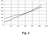
- FIG 2 typical temperature profiles in a heat exchanger used for converting liquid hydrogen to pressurized gaseous hydrogen and simultaneously liquefying pressurized gaseous nitrogen, such as heat exchanger 11 as illustrated in Figure 1 , are indicated in a diagram in which an amount of heat, Q, in kW, is indicated on the horizontal axis and a temperature, T, in K, is indicated on the vertical axis.
- the upper graph corresponds to the temperature profile for (liquefying) nitrogen at, in the specific example, 65 bar, which is cooled, in the example, to 82 K
- the lower graph corresponds to the temperature profile for (evaporating) hydrogen at, in the example, 60 bar.
- a corresponding apparatus is shown in Figure 3 and indicated with reference numeral 100. Elements already explained in connection with Figure 1 are indicated with like reference numerals. An essential difference is that, instead of a single heat exchanger, such as heat exchanger 11 in Figure 1 , a first heat exchanger and a second heat exchanger, which are, for reasons of generality, referred to as "first heat transfer unit” and “second heat transfer unit” and indicated with 111 and 112, are used.
- a heat transfer system including first and second heat transfer units is indicated with reference numeral 110.
- first and second heat transfer units 111, 112 may be provided as connected or unconnected heat exchanger blocks or may be integrated into a single heat transfer apparatus as generally known in the field.
- the first stream 1 is passed cocurrently with the second stream 2 through the first heat transfer unit 111 and countercurrently with the second stream 2 through the second heat transfer unit 112.
- the first stream 1 is passed through the first heat transfer unit 111 and thereafter through the second heat transfer unit 112
- the second stream is passed through the second heat transfer unit 112 and thereafter through the first heat transfer unit 111.
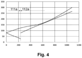
- FIG 4 typical temperature profiles in a heat transfer system 110, e.g. as illustrated in Figure 3 , are shown.
- the left part referred to with 111a corresponds to first heat transfer unit 111 while the right part referred to with 112a corresponds to second heat exchanger unit 12 as illustrated in Figure 3 .
- an amount of heat, Q, in kW is indicated on the horizontal axis and a temperature, T, in K, is indicated on the vertical axis.
- the upper graph corresponds to the temperature profile for (liquefying) nitrogen at, in the specific example, and as above, 65 bar, which is cooled, in the example, and as above to 82 K
- the lower (interrupted) graph corresponds to the temperature profile for hydrogen at, in the example, and as above, 60 bar.
- the coldest hydrogen thermally contacts nitrogen at a pressure considerably higher than before, eliminating the risk of solidification.
Landscapes
- Engineering & Computer Science (AREA)
- Mechanical Engineering (AREA)
- General Engineering & Computer Science (AREA)
- Physics & Mathematics (AREA)
- Thermal Sciences (AREA)
- Chemical & Material Sciences (AREA)
- Chemical Kinetics & Catalysis (AREA)
- General Chemical & Material Sciences (AREA)
- Oil, Petroleum & Natural Gas (AREA)
- Separation By Low-Temperature Treatments (AREA)
Abstract
A method for converting liquid hydrogen (LH2) to pressurized gaseous hydrogen (PGH2) is provided, wherein the liquid hydrogen (LH2) is pressurized, wherein a first stream formed from the pressurized liquid hydrogen (LH2) is passed through a heat transfer system (110), and wherein a second stream formed from a gaseous pressurized fluid (HPGAN) is also passed through the heat transfer system (110). The heat transfer system (110) comprises a first heat transfer unit (111) and a second heat transfer unit (112), the first stream is passed cocurrently with the second stream through the first heat transfer unit (111) and countercurrently with the second stream through the second heat transfer unit (112), the first stream is passed through the first heat transfer unit (111) and thereafter through the second heat transfer unit (112), and the second stream is passed through the second heat transfer unit (112) and thereafter through the first heat transfer unit (111). A corresponding apparatus (100) is also proposed herein.
Description
- The present invention relates to a method and an apparatus for converting liquid hydrogen to pressurized gaseous hydrogen.
- For conversion of liquid hydrogen to pressurized gaseous hydrogen, the liquid hydrogen may be pressurized from a first pressure to a second pressure, e.g., by means of a cryogenic pump, and thereafter warmed up to a temperature close to ambient by applying heat power from an external source by means of a heat exchanger, often referred to as evaporator.
- Reference is made expert literature and to
Figure 1 discussed hereinbelow, which illustrates anon-inventive apparatus 10 for converting liquid hydrogen to pressurized gaseous hydrogen. The purpose of usingapparatus 10, or similar type of apparatus, is that the hydrogen after pressurization is still very cold, i.e., the temperature is usually lower than 40 K, and this stream therefore has considerable value in terms of (cooling) power. Coupling of hydrogen evaporation with an application requiring cold, such as nitrogen liquefaction in the example ofFigure 1 , is therefore advantageous. - Against this background, a method and an apparatus for converting liquid hydrogen to pressurized gaseous hydrogen are proposed. Embodiments are the subject matter of the dependent claims and of the description that follows hereinbelow.
- A method for converting liquid hydrogen to pressurized gaseous hydrogen is proposed herein, wherein the liquid hydrogen is pressurized, wherein a first stream formed from the pressurized liquid hydrogen is passed through a heat transfer system, and wherein a second stream formed from a gaseous pressurized fluid is also passed through the heat transfer system.
- In the method proposed herein, the heat transfer system comprises a first heat transfer unit and a second heat transfer unit. The first stream is passed cocurrently with the second stream through the first heat transfer unit and countercurrently with the second stream through the second heat transfer unit, the first stream is passed through the first heat transfer unit and thereafter through the second heat transfer unit, and the second stream is passed through the second heat transfer unit and thereafter through the first heat transfer unit.
- In certain embodiments, heat transfer units and systems in the form of plate-fin heat exchangers, in particular brazed aluminium plate-fin heat exchangers (PFHE, see ISO 15547-2:3005) may be used. Characteristics of such heat exchangers are shown and described in particular in
Figure 2 of the aforementioned ISO 15547-2:3005 and on page 5 of the publication "The Standards of the Brazed Aluminium Plate-Fin Heat Exchanger Manufacturers' Association" by ALPEMA, 3rd edition 2010. - Plate-fin heat exchangers can be used in a variety of process plants at a wide range of pressures and temperatures. They are used, for example, in the cryogenic separation of air, in the liquefaction of natural gas or in plants for the production of ethylene. If the term "heat exchanger", "heat transfer unit" or "heat transfer system" is used in the following, this can always refer to a brazed aluminium plate-fin heat exchanger or a system including such a heat exchanger. In particular, such a heat exchanger may be made of aluminium, where "aluminium" can also refer to an aluminium alloy.
- In such heat exchangers, channels for the fluids to be passed through the heat exchanger are formed by means of so-called fins, i.e. by means of structured metal sheets. Although these can be permeable, e.g. when using perforated plates, they define at least one preferred direction of the fluid flow and therefore represent fluid guiding devices. The fins or the structuring of corresponding sheets can be designed with different geometries, e.g. triangular, rectangular, wave-shaped, lamellar, perforated, toothed or with so-called staggered strip lamellas. The fins also keep the separator plates arranged between the respective plates of the plate heat exchanger at a distance. It is known, for example, that distributor and collector fins are used to distribute the injected fluid to the fins running in the central area of the plate heat exchanger, typically in a horizontal or vertical direction, or to collect it from them. Distributor and collector fins are fluid-connected to a feed header on the one hand and a collector header on the other. A feed header in the condensation passages of a condenser evaporator is a gas inlet, a collection header is a liquid outlet, even if in certain cases non-condensed gas is also withdrawn via the latter.
- In certain embodiments disclosed herein, a plate-fin heat exchanger may not be usable or advantageous in all cases, e.g., in the case of the first heat transfer unit, particularly due to large temperature differences. In such cases, a spiral wound heat exchanger, sometimes also referred to as coil-wound heat exchanger, may be used.
- Spiral wound heat exchangers are often used in natural gas liquefaction processes and are described, e.g., in H.-W. Häring (eds.), Industrial Gases Processing, Wiley-VCH, 2006, especially section 7.6, "Process of Natural Gas Treatment" at pages 234 and 235. In a spiral wound heat exchanger, a large number of heat exchanger tubes, sometimes several thousand, are wound onto a central core tube (mandrel). The manufacturing process of a spiral wound heat exchanger may be comparable to winding yarn onto a spool. In this way, huge heating surfaces of several tens of thousands of square metres can be accommodated in one apparatus. In the tubes, the streams to be cooled are arranged upwards. On the shell side, the cold flow, in the present case evaporating hydrogen, falls down, cooling all the tubes evenly.
- Spiral wound heat exchangers are mechanically robust, but, for design reasons, typically only one shell stream can be routed against several tube streams. Plate-fin heat exchangers, in contrast, are much more flexible in terms of flow arrangement. However, many parallel cores are required due to the limited core dimensions and plate-fin heat exchangers are also more sensitive to temperature differences due tot he brazed metal connections.
- If, herein, it is mentioned that a "stream" is passed through a heat transfer unit, it comes without saying that such fluid may be passed through a heat transfer unit parallelly in the form of partial streams, particularly in different heat exchanger plates. If a "heat transfer unit" is mentioned here, this may be a separate heat exchanger block or a "heat transfer unit" may be a certain section of a common block. Commonly, the heat transfer units are referred to as a "heat transfer system".
- Using a method as proposed herein solves problems resulting from the still very cold liquid hydrogen after pressurization. This temperature is usually lower than 40 K, which is also lower than solidification temperature of the nitrogen at about 63 K. The risk that nitrogen solidifies inside of the heat exchanger (if cooled to temperatures below 63 K) is therefore, in conventional methods, considerably high. In case of nitrogen solidification, the corresponding channels of the heat exchanger will be blocked, an operation of this device is not secured. Usually, the system needs to be stopped for maintenance (warming-up, removal of solids etc.).
- Embodiments as proposed herein now include, as mentioned in other words before, that the ("first") hydrogen stream after being passed through the pump is not thermally contacted with the nitrogen stream (or another "second" stream containing nitrogen, as mentioned below) at the coldest temperature thereof, i.e. at the cold end of a single heat exchanger, but at a higher temperature. This becomes possible by the cocurrent operation of the first heat transfer unit. Therefore, the risk of solidification of nitrogen and a blockage of a heat exchanger or heat transfer unit is minimized.
- In yet other words, in the first heat transfer unit (which is operated at colder temperatures), the first stream and the second stream are thermally contacted in cocurrent flow. The warmer second stream is cooled by the first stream, i.e., cold hydrogen, from an intermediate temperature level to a liquid nitrogen temperature level, while the colder first stream is warmed up to roughly the same liquid nitrogen temperature level, but it is still colder than the second stream.
- In the second heat transfer unit (which is operated at warmer temperatures), the first and second streams are thermally contacted in a conventional way, i.e., in a countercurrent flow. The nitrogen is cooled from ambient temperature level to an intermediate temperature level, the hydrogen is warmed up to a temperature close to the ambient temperature level.
- The proposed method may be implemented with the same or similar capital expenses, but the operational expenses will be considerably reduced in the proposed method due to avoided/reduced maintenance and service efforts.
- In embodiments as proposed herein, the gaseous pressurized fluid is or comprises a dry, pure or purified nitrogen-containing fluid selected from air, nitrogen-enriched air, a mixture containing nitrogen, and pure nitrogen. Corresponding embodiments may therefore be used for a large variety of pressurized fluids.
- According to certain embodiments, the first stream may be heated from a temperature level of 30 to 40 K to a temperature level of 75 to 90 K by being passed through the first heat transfer unit, and the second stream may be cooled from a from a temperature level of 120 to 130 K to a temperature level of 75 to 90 K while being passed through the first heat transfer unit. As mentioned before, in such configurations the solidification temperature of nitrogen is never reached.
- Generally, the first stream may be passed through the first heat transfer unit and the second heat transfer unit at a supercritical pressure level, which is higher than 13 bar, and/or the second stream may be passed through the second heat transfer unit and the first heat transfer unit at a supercritical pressure level. The pressure of the second stream, particularly if this is nitrogen, is therefore higher than 34 bar, but the higher the pressure the higher the process efficiency is. This is particularly the case at a pressure higher than 50 bar. The Pressure of hydrogen, i.e., the first stream, depends on demands, such as by a customer. For pipeline transport, it is usually higher than 30 bar. More specifically, the first stream may be passed through the first heat transfer unit and the second heat transfer unit at a pressure level of 30 to 100 bar, and/or the second stream may be passed through the second heat transfer unit and the first heat transfer unit at a pressure level of 15 to 100 bar,
- In embodiments, the second stream may be expanded into a storage tank after being passed through the second heat transfer unit to form a liquid phase and optionally also a flash gas. The liquid phase may be withdrawn from the storage tank as liquefaction product while the flash gas may be used as explained below.
- In certain embodiments, the flash gas just mentioned may be withdrawn from the storage tank and withdrawn from the method in an unheated form and/or it may be heated in the second heat transfer unit and the first heat transfer unit. In the former case, a cold gas may be provided and used in certain applications, while in the latter case, cold may be reused for liquefaction.
- In certain embodiments, the flash gas may be heated in the second heat transfer unit and the first heat transfer unit and this flash gas may thereafter be used in forming the second stream together with makeup fluid, i.e. it may be recycled to save energy.
- The first stream may be heated using external heat in a heater after having been passed through the heat transfer system, such as to adapt its temperature as required.
- An apparatus for converting liquid hydrogen to pressurized gaseous hydrogen, comprising a heat transfer system, is also proposed. The apparatus is configured to pressurize liquid hydrogen, to form a first stream from the pressurized liquid hydrogen and to pass the first stream through the heat transfer system, and to form a second stream from a gaseous pressurized fluid and to pass also the second stream passed through the heat transfer system.
- In the proposed apparatus, the heat transfer system comprises a first heat transfer unit and a second heat transfer unit, and that the apparatus is configured to pass the first stream cocurrently with the second stream through the first heat transfer unit and countercurrently with the second stream through the second heat transfer unit, and that the apparatus is configured to pass the first stream through the first heat transfer unit and thereafter through the second heat transfer unit, and to pass the second stream through the second heat transfer unit and thereafter through the first heat transfer unit.
- For further details in relation to the apparatus as provided according to the present disclosure and preferred embodiments thereof, reference is made to the explanations relating to the proposed method and its preferred embodiments above. Advantageously, the proposed arrangement is adapted to perform a method in at least one of the embodiments explained before in more detail.
-
-
Figure 1 illustrates an apparatus not forming part of the present invention, -
Figure 2 illustrates aspects of a method not forming part of the present invention, -
Figure 3 illustrates an apparatus according to an embodiment, and -
Figure 4 illustrates aspects of a method according to an embodiment. - In the Figures, elements of identical, essentially identical, functionally comparable, or technically compatible function and/or purpose may be identified with identical reference numerals, and repeated explanations may be omitted for reasons of conciseness. Explanations relating to devices, apparatus, arrangements, systems, etc., according to certain embodiments likewise may apply to methods, processes, procedures, etc., according to certain embodiments, and vice versa.
- The various embodiments described herein are presented only to assist in understanding and teaching the claimed features. These embodiments are provided as a representative sample of embodiments only, and are not exhaustive and/or exclusive. It is to be understood that advantages, embodiments, examples, functions, features, structures, and/or other aspects described herein are not to be considered limitations on the scope of the invention as defined by the claims or limitations on equivalents to the claims, and that other embodiments may be utilised and modifications may be made without departing from the scope of the claimed invention. Various embodiments of the invention may suitably comprise, consist of, or consist essentially of, appropriate combinations of the disclosed elements, components, features, parts, steps, means, etc., other than those specifically described herein. In addition, this disclosure may include other inventions not presently claimed, but which may be claimed in future, particularly when encompassed by the scope of the independent claims.
-
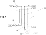
Figure 1 illustrates anon-inventive apparatus 10 for converting liquid hydrogen to pressurized gaseous hydrogen, in which a heat exchanger is indicated withreference numeral 11, a cryogenic pump is indicated withreference numeral 12, an optional heater is indicated withreference numeral 13, a storage tank for liquid nitrogen is indicated withreference numeral 14, and an expansion valve is indicated withreference numeral 15. - In
Figure 1 , moreover, liquid hydrogen is referred to with LH2, pressurized gaseous nitrogen with PGH2, and the first and second pressures mentioned are referred to with p1 and p2. A temperature of the liquid hydrogen LH2 before being passed throughheat exchanger 11 may be in a range of about 30 to 40 K. -
Heat exchanger 11 is operated using high pressure gaseous nitrogen HPGAN which is provided in a dry state and an uncontaminated form at a supercritical pressure p11. Gaseous nitrogen HPGAN is passed throughheat exchanger 11 and withdrawn therefrom at a temperature in a range of about 75 to 90 K before being expanded inexpansion valve 15 to a pressure p12 and intostorage tank 14. For clarity, a first stream formed from the liquid hydrogen LH2 is referred to with 1 and a second stream formed from the pressurized gaseous nitrogen HPGAN is referred to with 2. - From
storage tank 14, liquid nitrogen LIN and optionally gaseous nitrogen GAN, i.e., flash gas, may be withdrawn. Alternatively or additionally to the latter, gaseous nitrogen GAN may optionally be heated inheat exchanger 11 and may be withdrawn fromapparatus 10 at the warm end. After leaving the heat exchanger, this gas can be vented into ambient. Optionally, it may be re-compressed to a high-pressure level and added to the main nitrogen flow. These options are indicated by dashed lines. - Therefore, as mentioned in other words before, in
apparatus 10, cold pressurized hydrogen LH2 (after pressurization) is passed throughheat exchanger 11 from the cold end to the warm end, and warm (ambient temperature) pressurized gaseous nitrogen HPGAN is provided through the other channels of theheat exchanger 11 in counterflow to the hydrogen stream LH2, i.e., from the warm end to the cold end ofheat exchanger 11. Inheat exchanger 11, the cold hydrogen stream LH2 is warmed up, and simultaneously the pressurized gaseous nitrogen HPGAN is cooled to a temperature level of 80 K and liquefied, due to heat exchange through the heat exchanger surface, wherein the cooling capacity of the cold hydrogen LH2 stream is applied to the warm pressurized nitrogen stream HPGAN.Apparatus 10 may be used if large amounts of nitrogen need to be liquefied, and if a high efficiency of the process is targeted for. - Some or all pressures used in
apparatus 10 may be the result of design considerations, e.g., low pressure level p12 may be defined by a storage design pressure. For example, if a flat bottom tank is used for storage, the pressure level p12 may be selected to be very close to the ambient pressure. If a cylindrical storage vessel is used, the pressure level p12 may usually still be lower than 10 bar. - Liquid hydrogen LH2 which is pressurized from a first pressure p1 to a second, high pressure p2 by means of
cryogenic pump 12 is passed throughheat exchanger 11 in counter-current flow to the main nitrogen stream HPGAN. The hydrogen LH2 is heated there. Ideally, the hydrogen leaves theheat exchanger 11 with a temperature close to ambient temperature. Sometimes, the process properties (temperature profile) are nonoptimal and the hydrogen leaves the heat exchanger with a lower temperature. In this case, it can be warmed up further, by means of a separate heater (heat exchanger) by heat provided from an external heat source inheater 13. - In
Figure 2 , typical temperature profiles in a heat exchanger used for converting liquid hydrogen to pressurized gaseous hydrogen and simultaneously liquefying pressurized gaseous nitrogen, such asheat exchanger 11 as illustrated inFigure 1 , are indicated in a diagram in which an amount of heat, Q, in kW, is indicated on the horizontal axis and a temperature, T, in K, is indicated on the vertical axis. The upper graph corresponds to the temperature profile for (liquefying) nitrogen at, in the specific example, 65 bar, which is cooled, in the example, to 82 K, and the lower graph corresponds to the temperature profile for (evaporating) hydrogen at, in the example, 60 bar. - The pressurized hydrogen LH2 (after pressurization) is, as mentioned, and as can directly be seen from
Figure 2 , still very cold. The temperature of this stream is usually lower than 50 K, which is also lower than the solidification temperature of nitrogen at about 63 K. The risk that the nitrogen stream can be solidified inside of the heat exchanger (if cooled to a temperature below 63 K) is therefore high. In case of nitrogen solidification, the nitrogen channels of the heat exchanger will be blocked, and an operation may be no longer possible. Usually, the system needs to be stopped for maintenance (warming-up, removal of solids etc.). - In embodiments disclosed herein, therefore, a corresponding method and apparatus is changed in such a way that the coldest hydrogen stream (after pressurization) is never connected thermally to the coldest nitrogen stream. Therefore, the risk of solidification of nitrogen and blockage of heat exchanger is minimized.
- A corresponding apparatus is shown in
Figure 3 and indicated withreference numeral 100. Elements already explained in connection withFigure 1 are indicated with like reference numerals. An essential difference is that, instead of a single heat exchanger, such asheat exchanger 11 inFigure 1 , a first heat exchanger and a second heat exchanger, which are, for reasons of generality, referred to as "first heat transfer unit" and "second heat transfer unit" and indicated with 111 and 112, are used. A heat transfer system including first and second heat transfer units is indicated with reference numeral 110. As mentioned, first and second heat transfer units 111, 112 may be provided as connected or unconnected heat exchanger blocks or may be integrated into a single heat transfer apparatus as generally known in the field. - As shown in
Figure 3 , for converting liquid hydrogen LH2 to pressurized gaseous hydrogen PGH2, wherein the liquid hydrogen LH2 is pressurized from a first pressure p1 to a second pressure p2 usingcryogenic pump 12, and a "first"stream 1 formed from the pressurized liquid hydrogen LH2 is passed through the heat transfer system 110. A "second"stream 2 formed from a gaseous pressurized fluid, which is here gaseous nitrogen HPGAN is also passed through the heat transfer system 110. - The
first stream 1 is passed cocurrently with thesecond stream 2 through the first heat transfer unit 111 and countercurrently with thesecond stream 2 through the second heat transfer unit 112. In this connection, thefirst stream 1 is passed through the first heat transfer unit 111 and thereafter through the second heat transfer unit 112, and the second stream is passed through the second heat transfer unit 112 and thereafter through the first heat transfer unit 111. - In
Figure 4 , typical temperature profiles in a heat transfer system 110, e.g. as illustrated inFigure 3 , are shown. The left part referred to with 111a corresponds to first heat transfer unit 111 while the right part referred to with 112a corresponds to secondheat exchanger unit 12 as illustrated inFigure 3 . As inFigure 2 , an amount of heat, Q, in kW, is indicated on the horizontal axis and a temperature, T, in K, is indicated on the vertical axis. The upper graph corresponds to the temperature profile for (liquefying) nitrogen at, in the specific example, and as above, 65 bar, which is cooled, in the example, and as above to 82 K, and the lower (interrupted) graph corresponds to the temperature profile for hydrogen at, in the example, and as above, 60 bar. - As can be seen, the coldest hydrogen thermally contacts nitrogen at a pressure considerably higher than before, eliminating the risk of solidification.
Claims (14)
- A method for converting liquid hydrogen (LH2) to pressurized gaseous hydrogen (PGH2), wherein the liquid hydrogen (LH2) is pressurized, wherein a first stream formed from the pressurized liquid hydrogen (LH2) is passed through a heat transfer system (110), and wherein a second stream formed from a gaseous pressurized fluid (HPGAN) is also passed through the heat transfer system (110), characterized in that the heat transfer system (110) comprises a first heat transfer unit (111) and a second heat transfer unit (112), that the first stream is passed cocurrently with the second stream through the first heat transfer unit (111) and countercurrently with the second stream through the second heat transfer unit (112), that the first stream is passed through the first heat transfer unit (111) and thereafter through the second heat transfer unit (112), and that the second stream is passed through the second heat transfer unit (112) and thereafter through the first heat transfer unit (111).
- The method according to claim 1, wherein the gaseous pressurized fluid (HPGAN) is or comprises a dry, pure or purified nitrogen-containing fluid selected from air, nitrogen-enriched air, a mixture containing nitrogen, and pure nitrogen.
- The method according to claim 1 or 2, wherein the first stream is heated from a temperature level of 30 to 40 K to a temperature level of 75 to 90 K by being passed through the first heat transfer unit (111), and wherein the second stream is cooled from a from a temperature level of 120 to 130 K to a temperature level of 75 to 90 K while being passed through the first heat transfer unit (111).
- The method according to any one of the preceding claims, wherein the first stream is passed through the first heat transfer unit (111) and the second heat transfer unit (112) at a supercritical pressure level, and/or wherein the second stream is passed through the second heat transfer unit (112) and the first heat transfer unit (111) at a supercritical pressure level.
- The method according to claim 4, wherein the first stream is passed through the first heat transfer unit (111) and the second heat transfer unit (112) at a pressure level of 30 to 100 bar, and/or wherein the second stream is passed through the second heat transfer unit (112) and the first heat transfer unit (111) at a pressure level of 15 to 100 bar.
- The method according to any one of the preceding claims, wherein the second stream is expanded into a storage tank (14) after being passed through the second heat transfer unit (112) to form a liquid phase (LIN).
- The method according to claim 6, wherein a flash gas (GAN) is also formed when the second stream is expanded into a storage tank (14) after being passed through the second heat transfer unit (112) to form the liquid phase (LIN).
- The method according to claim 7, wherein the flash gas is withdrawn from the storage tank (14) and withdrawn from the method in an unheated form and/or heated in the second heat transfer unit (112) and the first heat transfer unit (111).
- The method according to claim 8, wherein flash gas is heated in the second heat transfer unit (112) and the first heat transfer unit (111) and wherein this flash gas is used in forming the second stream.
- The method according to any one of the preceding claims, wherein the first stream is heated using external heat in a heater (13) after having been passed through the heat transfer system (110).
- An apparatus (100) for converting liquid hydrogen (LH2) to pressurized gaseous hydrogen (PGH2), comprising a heat transfer system (110), wherein the apparatus (100) is configured to pressurize liquid hydrogen (LH2) from a first pressure (p1) to a second pressure (p2), to form a first stream from the pressurized liquid hydrogen (LH2) and to pass the first stream through the heat transfer system (110), and to form a second stream from a gaseous pressurized fluid (HPGAN) and to pass also the second stream passed through the heat transfer system (110), characterized in that the heat transfer system (110) comprises a first heat transfer unit (111) and a second heat transfer unit (112), and that the apparatus (100) is configured to pass the first stream cocurrently with the second stream through the first heat transfer unit (111) and countercurrently with the second stream through the second heat transfer unit (112), and that the apparatus (100) is configured to pass the first stream through the first heat transfer unit (111) and thereafter through the second heat transfer unit (112), and to pass the second stream is through the second heat transfer unit (112) and thereafter through the first heat transfer unit (111).
- The apparatus (100) according to claim 11, configured to perform a method according to any one of claims 1 to 11.
- The apparatus (100) according to claim 11 or 12, wherein the second heat transfer unit (112) is provided as, or includes a, plate fin heat exchanger
- The apparatus (100), according to any one of claims 11 to 13, wherein the first heat (111) is provided as, or includes a, spiral wound heat exchanger
Priority Applications (1)
| Application Number | Priority Date | Filing Date | Title |
|---|---|---|---|
| EP23020407.5A EP4517237A1 (en) | 2023-08-31 | 2023-08-31 | Process and system for conversion of liquid hydrogen to pressurized gaseous hydrogen |
Applications Claiming Priority (1)
| Application Number | Priority Date | Filing Date | Title |
|---|---|---|---|
| EP23020407.5A EP4517237A1 (en) | 2023-08-31 | 2023-08-31 | Process and system for conversion of liquid hydrogen to pressurized gaseous hydrogen |
Publications (1)
| Publication Number | Publication Date |
|---|---|
| EP4517237A1 true EP4517237A1 (en) | 2025-03-05 |
Family
ID=87889879
Family Applications (1)
| Application Number | Title | Priority Date | Filing Date |
|---|---|---|---|
| EP23020407.5A Withdrawn EP4517237A1 (en) | 2023-08-31 | 2023-08-31 | Process and system for conversion of liquid hydrogen to pressurized gaseous hydrogen |
Country Status (1)
| Country | Link |
|---|---|
| EP (1) | EP4517237A1 (en) |
Citations (3)
| Publication number | Priority date | Publication date | Assignee | Title |
|---|---|---|---|---|
| US5025623A (en) * | 1988-09-13 | 1991-06-25 | Mitsubishi Jukogyo Kabushiki Kaisha | Rocket engine |
| FR3017009A1 (en) * | 2014-01-30 | 2015-07-31 | Claude Favy | METHOD FOR STORING, TRANSPORTING AND RETURNING ELECTRICAL ENERGY |
| WO2023100072A1 (en) * | 2021-12-03 | 2023-06-08 | Saipem S.P.A. | Stabilization process for the electrical network, the gas network and/or the hydrogen network |
-
2023
- 2023-08-31 EP EP23020407.5A patent/EP4517237A1/en not_active Withdrawn
Patent Citations (3)
| Publication number | Priority date | Publication date | Assignee | Title |
|---|---|---|---|---|
| US5025623A (en) * | 1988-09-13 | 1991-06-25 | Mitsubishi Jukogyo Kabushiki Kaisha | Rocket engine |
| FR3017009A1 (en) * | 2014-01-30 | 2015-07-31 | Claude Favy | METHOD FOR STORING, TRANSPORTING AND RETURNING ELECTRICAL ENERGY |
| WO2023100072A1 (en) * | 2021-12-03 | 2023-06-08 | Saipem S.P.A. | Stabilization process for the electrical network, the gas network and/or the hydrogen network |
Non-Patent Citations (4)
| Title |
|---|
| "Industrial Gases Processing", 2006, WILEY-VCH, article "Process of Natural Gas Treatment", pages: 234,235 |
| "The Standards of the Brazed Aluminium Plate-Fin Heat Exchanger Manufacturers' Association", 2010, ALPEMA |
| QI MENG ET AL: "Advanced integration of LNG regasification power plant with liquid air energy storage: Enhancements in flexibility, safety, and power generation", APPLIED ENERGY, ELSEVIER SCIENCE PUBLISHERS, GB, vol. 269, 28 April 2020 (2020-04-28), XP086165219, ISSN: 0306-2619, [retrieved on 20200428], DOI: 10.1016/J.APENERGY.2020.115049 * |
| ROJEY A ET AL: "CryoEnergy form LNG regasification to pipeline specification", AICHE SPRING MEETING. NATURAL GAS UTILIZATION CONFERENCE, X, US, 1 January 2007 (2007-01-01), pages 332 - 345, XP009097534 * |
Similar Documents
| Publication | Publication Date | Title |
|---|---|---|
| US7040387B2 (en) | Heat transfer device | |
| CN216115518U (en) | Coiled heat exchanger and system for liquefying feed gas | |
| EP2242974A2 (en) | Air separation method and apparatus | |
| KR20160129100A (en) | Natural gas liquefying system and liquefying method | |
| JP3715497B2 (en) | Method for producing oxygen | |
| KR20170085449A (en) | Method for obtaining an air product in an air separation plant and air separation plant | |
| TW422732B (en) | Method of and apparatus for air separation | |
| JP2009030966A (en) | Method and device for producing argon by low-temperature air separation | |
| CN110709653A (en) | Refrigeration system | |
| KR101784908B1 (en) | Re-liquefaction system of LNG vessel and micro-channel plate type heat exchanger for the same | |
| EP2365269A1 (en) | Heat exchanging and liuid separation apparatus | |
| US20110017429A1 (en) | Method For Vaporizing Cryogenic Liquid Through Heat Exchange Using Calorigenic Fluid | |
| US20220252345A1 (en) | Method for operating a heat exchanger, arrangement with a heat exchanger, and system with a corresponding arrangement | |
| US20100206004A1 (en) | Main Exchange Line And Cryogenic Distillation Air Separation Unit Incorporating Such An Exchange Line | |
| AU2018335790B2 (en) | Mixed refrigerant system and method | |
| EP4517238A1 (en) | Method and apparatus for providing liquid air products | |
| US20100319877A1 (en) | Removable Flow Diversion Baffles for Liquefied Natural Gas Heat Exchangers | |
| US20150168054A1 (en) | Method and Apparatus for Separating a Carbon Dioxide-rich Gas | |
| AU2020329293B2 (en) | Heat exchanger system and method | |
| CN104620067B (en) | For by the method and apparatus of separating air by cryogenic distillation | |
| CN101233378A (en) | Wound heat exchangers with different tube diameters | |
| US20230068126A1 (en) | Flexible process and apparatus for the liquefaction of oxygen | |
| US12442593B2 (en) | Method for operating an air separation plant, having a distillation column system, a heat exchanger and an adsorber, and air separation plant | |
| CN114846287A (en) | Method and apparatus for providing an oxygen product | |
| Mollekopf et al. | Multistream Heat Exchangers—Types, Capabilities and Limits of Design |
Legal Events
| Date | Code | Title | Description |
|---|---|---|---|
| PUAI | Public reference made under article 153(3) epc to a published international application that has entered the european phase |
Free format text: ORIGINAL CODE: 0009012 |
|
| STAA | Information on the status of an ep patent application or granted ep patent |
Free format text: STATUS: THE APPLICATION HAS BEEN PUBLISHED |
|
| AK | Designated contracting states |
Kind code of ref document: A1 Designated state(s): AL AT BE BG CH CY CZ DE DK EE ES FI FR GB GR HR HU IE IS IT LI LT LU LV MC ME MK MT NL NO PL PT RO RS SE SI SK SM TR |
|
| STAA | Information on the status of an ep patent application or granted ep patent |
Free format text: STATUS: THE APPLICATION IS DEEMED TO BE WITHDRAWN |
|
| 18D | Application deemed to be withdrawn |
Effective date: 20250906 |