EP4517209A1 - Flow heater and method for operating a flow heater - Google Patents
Flow heater and method for operating a flow heater Download PDFInfo
- Publication number
- EP4517209A1 EP4517209A1 EP23193678.2A EP23193678A EP4517209A1 EP 4517209 A1 EP4517209 A1 EP 4517209A1 EP 23193678 A EP23193678 A EP 23193678A EP 4517209 A1 EP4517209 A1 EP 4517209A1
- Authority
- EP
- European Patent Office
- Prior art keywords
- module
- heater
- flow heater
- flow
- modules
- Prior art date
- Legal status (The legal status is an assumption and is not a legal conclusion. Google has not performed a legal analysis and makes no representation as to the accuracy of the status listed.)
- Pending
Links
Images

Classifications
-
- F—MECHANICAL ENGINEERING; LIGHTING; HEATING; WEAPONS; BLASTING
- F24—HEATING; RANGES; VENTILATING
- F24H—FLUID HEATERS, e.g. WATER OR AIR HEATERS, HAVING HEAT-GENERATING MEANS, e.g. HEAT PUMPS, IN GENERAL
- F24H1/00—Water heaters, e.g. boilers, continuous-flow heaters or water-storage heaters
- F24H1/0072—Special adaptations
- F24H1/009—Special adaptations for vehicle systems
-
- F—MECHANICAL ENGINEERING; LIGHTING; HEATING; WEAPONS; BLASTING
- F24—HEATING; RANGES; VENTILATING
- F24H—FLUID HEATERS, e.g. WATER OR AIR HEATERS, HAVING HEAT-GENERATING MEANS, e.g. HEAT PUMPS, IN GENERAL
- F24H1/00—Water heaters, e.g. boilers, continuous-flow heaters or water-storage heaters
- F24H1/10—Continuous-flow heaters, i.e. heaters in which heat is generated only while the water is flowing, e.g. with direct contact of the water with the heating medium
- F24H1/101—Continuous-flow heaters, i.e. heaters in which heat is generated only while the water is flowing, e.g. with direct contact of the water with the heating medium using electric energy supply
- F24H1/102—Continuous-flow heaters, i.e. heaters in which heat is generated only while the water is flowing, e.g. with direct contact of the water with the heating medium using electric energy supply with resistance
-
- F—MECHANICAL ENGINEERING; LIGHTING; HEATING; WEAPONS; BLASTING
- F24—HEATING; RANGES; VENTILATING
- F24H—FLUID HEATERS, e.g. WATER OR AIR HEATERS, HAVING HEAT-GENERATING MEANS, e.g. HEAT PUMPS, IN GENERAL
- F24H1/00—Water heaters, e.g. boilers, continuous-flow heaters or water-storage heaters
- F24H1/10—Continuous-flow heaters, i.e. heaters in which heat is generated only while the water is flowing, e.g. with direct contact of the water with the heating medium
- F24H1/12—Continuous-flow heaters, i.e. heaters in which heat is generated only while the water is flowing, e.g. with direct contact of the water with the heating medium in which the water is kept separate from the heating medium
- F24H1/121—Continuous-flow heaters, i.e. heaters in which heat is generated only while the water is flowing, e.g. with direct contact of the water with the heating medium in which the water is kept separate from the heating medium using electric energy supply
-
- F—MECHANICAL ENGINEERING; LIGHTING; HEATING; WEAPONS; BLASTING
- F24—HEATING; RANGES; VENTILATING
- F24H—FLUID HEATERS, e.g. WATER OR AIR HEATERS, HAVING HEAT-GENERATING MEANS, e.g. HEAT PUMPS, IN GENERAL
- F24H9/00—Details
- F24H9/18—Arrangement or mounting of grates or heating means
- F24H9/1809—Arrangement or mounting of grates or heating means for water heaters
- F24H9/1818—Arrangement or mounting of electric heating means
-
- F—MECHANICAL ENGINEERING; LIGHTING; HEATING; WEAPONS; BLASTING
- F24—HEATING; RANGES; VENTILATING
- F24H—FLUID HEATERS, e.g. WATER OR AIR HEATERS, HAVING HEAT-GENERATING MEANS, e.g. HEAT PUMPS, IN GENERAL
- F24H9/00—Details
- F24H9/20—Arrangement or mounting of control or safety devices
- F24H9/2007—Arrangement or mounting of control or safety devices for water heaters
- F24H9/2014—Arrangement or mounting of control or safety devices for water heaters using electrical energy supply
- F24H9/2028—Continuous-flow heaters
-
- F—MECHANICAL ENGINEERING; LIGHTING; HEATING; WEAPONS; BLASTING
- F24—HEATING; RANGES; VENTILATING
- F24H—FLUID HEATERS, e.g. WATER OR AIR HEATERS, HAVING HEAT-GENERATING MEANS, e.g. HEAT PUMPS, IN GENERAL
- F24H2250/00—Electrical heat generating means
- F24H2250/02—Resistances
Definitions
- the invention refers to a flow heater for heating liquids in an automotive vehicle.
- Flow heaters are needed in vehicles to heat various liquids, in particular water or aqueous solutions and oil.
- the heating power needed in commercial vehicles is usually about two to three times higher than heating power needed in passenger cars.
- the flow heater comprises several heating modules that are connected in series or in parallel to a single inlet and a single outlet.
- the flow heater comprises several heater modules, the number of interfaces for connection to a commercial vehicle is not increased in comparison to prior art flow heaters for commercial vehicles.
- the heater modules can be provided with a power rating suitable for passenger vehicles and therefore produced cost-efficiently in very large numbers.
- the invention thereby shows how flow heaters for commercial vehicles can be produced at lower cost and still be installed fairly easily in a commercial vehicle.
- the present invention effectively uses several flow heaters suitable for passenger vehicles in a commercial vehicle while the interfaces to the vehicles are kept like it would be with a single flow heater of higher power.
- the heater modules may have a heating power of 3 kW to 6 kW, and the flow heater may comprise two to four heater modules.
- the heating power of the flow heater may for example be in the range of 8 kW to 14 kW.
- the heating power of each heater module may be set individually. This means that the various heater modules of the flow heater may be operated with different heating powers. If the various heater modules are connected in series, the temperature of liquid to be heated rises from the first heater module to the last. The heating power of the heater modules may decrease from the first heater module to the last in order to achieve the most efficient heat transfer.
- each heating module may be provided with temperature sensors that are used by a control unit of the flow heater to monitor operation of the various heater modules.
- the control unit may communicate with a vehicle control unit and provide operating parameters to the vehicle control unit. For example, the control unit may diagnose an operating condition of the various heater modules and store that condition in a memory. The operating condition may then be considered in setting the heating power of the various modules and, especially if a fault condition of a module was detected, reported to the vehicle control unit.
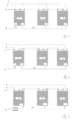
- Fig. 1 shows schematically a circuit diagram of a flow heater comprising three heater modules 1 which each have a module inlet 2 and a module outlet 3.
- the module inlets 2 are connected in parallel to an inlet 4 of the flow heater and the module outlets 3 are connected in parallel to an outlet 5 of the flow heater.
- liquid to be heated flows from the inlet 4 of the flow heater in parallel through the heater modules 1 and then to the outlet 5 of the flow heater.
- the module inlets 2 and the module outlets 3 may comprise a spigot, e.g. as shown in fig.1 . It is also possible to connect a module outlet 3 directly to a module inlet 2.
- a heater module 1 may have a module inlet 2 on an upper side and a module outlet on a lower side such that stacking modules on top of each other connects the module inlet of a heater module to the module outlet of the heater module above.
- a seal e.g. on O-ring, may be used between a module outlet and a module inlet.
- the flow heater has an electrical interface 6 for connection to a source of heating current, e.g., a high voltage source.
- the electrical interface 6 is connected in parallel to electrical module interfaces 7 to provide heating power to the heating modules 1.
- the flow heater also has another electrical interface 8 for connection to a control unit of a vehicle.
- the electrical control interface 8 of the flow heater is connected only to one electrical module interface 9 of one of the heater modules 1.
- This heater module 1 is connected via an internal bus 10 to the other heater modules 1 and controls them according to commands received via the electrical interface 8 of the flow heater.
- a master-slave architecture may be used for control of the heater modules, wherein the heater module connected to the electrical control interface 8 of the vehicle acts as a master that controls the other heater module as slaves via the internal bus 10.
- Fig. 2 shows schematically a circuit diagram of another flow heater comprising three heater modules 1. This embodiment differs from the embodiment of fig. 1 discussed above only in that liquid to be heated flows from the inlet 4 of the flow heater in series through the heater modules 1 and then to the outlet 5 of the flow heater.
- a parallel connection of the heater modules 1 as shown in fig. 1 results in a lower pressure loss compared to a serial connection of the heater modules 1 as shown in fig. 2 . This is advantageous in some applications, but larger fluid flows are needed for a parallel connection to prevent overheating.
- Fig. 3 shows schematically a circuit diagram of another flow heater comprising three heater modules 1. This embodiment differs from the embodiment of fig. 2 only in how the heater modules 1 are controlled.
- the electric control interface 8 of the flow heater is connected to a control unit 11 which controls all heater modules 1 via the internal bus 10. All heater modules 1 have an electronic module interface 9 that is connected to the internal bus 10 and via the internal bus 10 to the control unit 11.
- the control unit 11 is arranged between the electrical control interface 8 and the internal bus 10.
- the control unit 11 may be able to set the heating power of each heater module 1 individually. If the various heater modules are connected in series, the temperature of liquid to be heated rises from the first heater module to the last. The heating power of the heater modules may decrease from the first heater module to the last in order to achieve the most efficient heat transfer.
- each heater module 1 may be provided with a temperature sensor that is used by the control 11 unit of the flow heater to monitor operation of the various heater modules 1.
- the control unit 11 may communicate with a vehicle control unit via electrical interface 8 and provide operating parameters to the vehicle control unit.
- the control unit 4 may diagnose an operating condition of the various heater modules and store that condition in a memory. The operating condition may then be considered in setting the heating power of the various modules and, especially if a fault condition of a module was detected, reported to the vehicle control unit.
- Fig. 4 shows an embodiment of a heater module 1.
- the heater module 1 comprises a module inlet 2 for liquid to be heated, a module outlet 3, a heating element, e.g. an electrical heating resistor, for heating liquid flowing from the module inlet 2 to the module outlet 3, an electrical module interface 7 for heating current and another electrical module interface 9 for receiving control signals.
- the electrical module interface 9 might therefore also be called an electrical module control interface.
- the electrical interfaces 7, 9 may be provided as electrical plug connectors.
- Fig. 5 shows a flow heater comprising three heater modules 1 stacked on top of each other.
- the flow heather has an inlet 4 for liquid to be heated, an outlet 5 for heated liquid, an electrical interface 6 for connection to a source of heating current, e.g., a vehicle battery, and electrical control interface 8 for connection to a control unit of a vehicle.
- the electrical interfaces 6, 8 may be provided as electrical plug connectors.
- the flow heater comprises a frame 12 that carries the inlet 4, the outlet 5, connecting spigots that are connecting the inlet 4 and the outlet 5 to the module inlets 2 and the module outlets 3, respectively.
- the frame 12 also carries the electrical plug connectors defining the electrical interfaces 6, 8.
- the frame 12 may carry a control unit 11 as explained with reference to fig. 3 and an internal bus 10 connected to electrical module interfaces 9 of the heater modules.
- the frame 12 may comprise a plate that cover a front face of the heater modules 3 and on which the electrical connectors are arranged.
- the heater modules 1 are held by the frame 12.
- the frame 12 mechanically connects the heater modules 1 and thereby combines the heater modules 1 into a device that can be handled conveniently when it is mounted in a commercial vehicle.
Landscapes
- Engineering & Computer Science (AREA)
- Physics & Mathematics (AREA)
- Thermal Sciences (AREA)
- Chemical & Material Sciences (AREA)
- Combustion & Propulsion (AREA)
- Mechanical Engineering (AREA)
- General Engineering & Computer Science (AREA)
- Air-Conditioning For Vehicles (AREA)
- Instantaneous Water Boilers, Portable Hot-Water Supply Apparatuses, And Control Of Portable Hot-Water Supply Apparatuses (AREA)
Abstract
Disclosed is a flow heater comprising an inlet (4), an outlet (5), and an electrical interface (6, 8). The flow heater comprises a plurality of heater modules (1) that each comprise a module inlet (2) connected to the inlet (4), a module outlet (3) connected to the outlet (5), a heating element for heating liquid flowing from the module inlet (2) to the module outlet (3), and an electrical module interface (7, 9) connected to the electrical interface (6, 8).
Description
- The invention refers to a flow heater for heating liquids in an automotive vehicle.
- Flow heaters are needed in vehicles to heat various liquids, in particular water or aqueous solutions and oil. The heating power needed in commercial vehicles is usually about two to three times higher than heating power needed in passenger cars.
- It is an object of the present invention to reduce development effort and capital expenditures to deliver flow heaters for use in commercial vehicles.
- This object is solved by a flow heater according to
claim 1 and a method for operating such a flow heater. Advantageous refinements of the invention are the matter of dependent claims. - According to the present invention, the flow heater comprises several heating modules that are connected in series or in parallel to a single inlet and a single outlet. Although the flow heater comprises several heater modules, the number of interfaces for connection to a commercial vehicle is not increased in comparison to prior art flow heaters for commercial vehicles. The heater modules can be provided with a power rating suitable for passenger vehicles and therefore produced cost-efficiently in very large numbers. The invention thereby shows how flow heaters for commercial vehicles can be produced at lower cost and still be installed fairly easily in a commercial vehicle. The present invention effectively uses several flow heaters suitable for passenger vehicles in a commercial vehicle while the interfaces to the vehicles are kept like it would be with a single flow heater of higher power.
- For example, the heater modules may have a heating power of 3 kW to 6 kW, and the flow heater may comprise two to four heater modules. The heating power of the flow heater may for example be in the range of 8 kW to 14 kW.
- In a method for operating a flow heater the heating power of each heater module may be set individually. This means that the various heater modules of the flow heater may be operated with different heating powers. If the various heater modules are connected in series, the temperature of liquid to be heated rises from the first heater module to the last. The heating power of the heater modules may decrease from the first heater module to the last in order to achieve the most efficient heat transfer.
- In a further embodiment, each heating module may be provided with temperature sensors that are used by a control unit of the flow heater to monitor operation of the various heater modules. The control unit may communicate with a vehicle control unit and provide operating parameters to the vehicle control unit. For example, the control unit may diagnose an operating condition of the various heater modules and store that condition in a memory. The operating condition may then be considered in setting the heating power of the various modules and, especially if a fault condition of a module was detected, reported to the vehicle control unit.
- Further details and advantages of the invention are explained by means of examples of embodiments, with reference to the accompanying drawings. Equal and corresponding parts of various embodiments are provided with the same reference numbers in all figures.
- Fig. 1
- shows schematically a circuit diagram of a flow heater;
- Fig. 2
- shows schematically another circuit diagram of a flow heater;
- Fig. 3
- shows schematically another circuit diagram of a flow heater;
- Fig. 4
- a heater module of a flow heater; and
- Fig. 5
- a flow heater comprising three flow heaters.
-
Fig. 1 shows schematically a circuit diagram of a flow heater comprising threeheater modules 1 which each have amodule inlet 2 and amodule outlet 3. Themodule inlets 2 are connected in parallel to aninlet 4 of the flow heater and themodule outlets 3 are connected in parallel to anoutlet 5 of the flow heater. In operation, liquid to be heated flows from theinlet 4 of the flow heater in parallel through theheater modules 1 and then to theoutlet 5 of the flow heater. - The
module inlets 2 and themodule outlets 3 may comprise a spigot, e.g. as shown infig.1 . It is also possible to connect amodule outlet 3 directly to amodule inlet 2. For example, aheater module 1 may have amodule inlet 2 on an upper side and a module outlet on a lower side such that stacking modules on top of each other connects the module inlet of a heater module to the module outlet of the heater module above. A seal, e.g. on O-ring, may be used between a module outlet and a module inlet. - The flow heater has an
electrical interface 6 for connection to a source of heating current, e.g., a high voltage source. Theelectrical interface 6 is connected in parallel to electrical module interfaces 7 to provide heating power to theheating modules 1. The flow heater also has anotherelectrical interface 8 for connection to a control unit of a vehicle. In the embodiment shown, theelectrical control interface 8 of the flow heater is connected only to oneelectrical module interface 9 of one of theheater modules 1. Thisheater module 1 is connected via aninternal bus 10 to theother heater modules 1 and controls them according to commands received via theelectrical interface 8 of the flow heater. A master-slave architecture may be used for control of the heater modules, wherein the heater module connected to theelectrical control interface 8 of the vehicle acts as a master that controls the other heater module as slaves via theinternal bus 10. -
Fig. 2 shows schematically a circuit diagram of another flow heater comprising threeheater modules 1. This embodiment differs from the embodiment offig. 1 discussed above only in that liquid to be heated flows from theinlet 4 of the flow heater in series through theheater modules 1 and then to theoutlet 5 of the flow heater. - A parallel connection of the
heater modules 1 as shown infig. 1 results in a lower pressure loss compared to a serial connection of theheater modules 1 as shown infig. 2 . This is advantageous in some applications, but larger fluid flows are needed for a parallel connection to prevent overheating. -
Fig. 3 shows schematically a circuit diagram of another flow heater comprising threeheater modules 1. This embodiment differs from the embodiment offig. 2 only in how theheater modules 1 are controlled. Theelectric control interface 8 of the flow heater is connected to a control unit 11 which controls allheater modules 1 via theinternal bus 10. Allheater modules 1 have anelectronic module interface 9 that is connected to theinternal bus 10 and via theinternal bus 10 to the control unit 11. The control unit 11 is arranged between theelectrical control interface 8 and theinternal bus 10. - The control unit 11 may be able to set the heating power of each
heater module 1 individually. If the various heater modules are connected in series, the temperature of liquid to be heated rises from the first heater module to the last. The heating power of the heater modules may decrease from the first heater module to the last in order to achieve the most efficient heat transfer. - Moreover, each
heater module 1 may be provided with a temperature sensor that is used by the control 11 unit of the flow heater to monitor operation of thevarious heater modules 1. The control unit 11 may communicate with a vehicle control unit viaelectrical interface 8 and provide operating parameters to the vehicle control unit. For example, thecontrol unit 4 may diagnose an operating condition of the various heater modules and store that condition in a memory. The operating condition may then be considered in setting the heating power of the various modules and, especially if a fault condition of a module was detected, reported to the vehicle control unit. -
Fig. 4 shows an embodiment of aheater module 1. Theheater module 1 comprises amodule inlet 2 for liquid to be heated, amodule outlet 3, a heating element, e.g. an electrical heating resistor, for heating liquid flowing from themodule inlet 2 to themodule outlet 3, an electrical module interface 7 for heating current and anotherelectrical module interface 9 for receiving control signals. Theelectrical module interface 9 might therefore also be called an electrical module control interface. Theelectrical interfaces 7, 9 may be provided as electrical plug connectors. -
Fig. 5 shows a flow heater comprising threeheater modules 1 stacked on top of each other. The flow heather has aninlet 4 for liquid to be heated, anoutlet 5 for heated liquid, anelectrical interface 6 for connection to a source of heating current, e.g., a vehicle battery, andelectrical control interface 8 for connection to a control unit of a vehicle. Theelectrical interfaces - The
inlet 4 is connected in parallel to themodule inlets 2 of theheater modules 1 and theoutlet 5 is connected in parallel to themodule outlets 3. Theelectrical interface 6 is connected to the electrical module interfaces 7 as shown infigures 1 to 3 . Theelectrical control interface 8 may be connected to electrical control interfaces of theheater modules 1 as shown infig. 1, fig. 2 or fig. 3 . - The flow heater comprises a
frame 12 that carries theinlet 4, theoutlet 5, connecting spigots that are connecting theinlet 4 and theoutlet 5 to themodule inlets 2 and themodule outlets 3, respectively. Theframe 12 also carries the electrical plug connectors defining theelectrical interfaces frame 12 may carry a control unit 11 as explained with reference tofig. 3 and aninternal bus 10 connected toelectrical module interfaces 9 of the heater modules. Theframe 12 may comprise a plate that cover a front face of theheater modules 3 and on which the electrical connectors are arranged. - The
heater modules 1 are held by theframe 12. Theframe 12 mechanically connects theheater modules 1 and thereby combines theheater modules 1 into a device that can be handled conveniently when it is mounted in a commercial vehicle. -
- 1
- heater module
- 2
- module inlet
- 3
- module outlet
- 4
- inlet
- 5
- outlet
- 6
- electrical interface
- 7
- electrical module interface
- 8
- electrical interface
- 9
- electrical module interfaces
- 10
- internal bus
- 11
- control unit
- 12
- frame
Claims (15)
- Flow heater comprisingan inlet (4), an outlet (5), and an electrical interface (6, 8), characterized bya plurality of heater modules (1) that each comprisea module inlet (2) connected to the inlet (4),a module outlet (3) connected to the outlet (5),a heating element for heating liquid flowing from the module inlet (2) to the module outlet (3), andan electrical module interface (7, 9) connected to the electrical interface (6, 8).
- Flow heater according to claim 1, characterized in that the module inlets (2) of the heater modules (1) are connected in parallel to the inlet (4).
- Flow heater according to claim 1, characterized in that module heaters (1) are connected in series such that liquid to heated flows through the heater modules (1) one after the other.
- Flow heater according to any one of the preceding claims, characterized in that the heater modules (1) are stacked on top of each other.
- Flow heater according to any one of the preceding claims, characterized by a frame (12) that carries the electrical interface (7, 9), the inlet (4), the outlet (5), connecting spigots that are connecting the inlet (4) to the module inlets (2) and the outlet (5) to the module outlets (3), respectively.
- Flow heater according to claim 5, characterized in that the heater modules (1) are held by the frame (12).
- Flow heater according to any one of the preceding claims, characterized by an internal bus (10) connecting the module electrical interfaces (9).
- Flow heater according to claim 5 and 7, characterized in that the internal bus (10) is provided on the frame (12).
- Flow heater according to claim 7 or 8, characterized by a control unit (11) connected to the electrical interface (8) and to the internal bus (10).
- Flow heater according to claim 8 and 9, characterized in that the control unit (11) is provided on the frame (12).
- Flow heater according to claim 7 or 8, characterized in that one of heater modules (1) comprises a control unit that controls the other heater modules (1) via the internal bus (10).
- Flow heater according to any one of the preceding claims, characterized in that the electrical interface (6, 8) comprises a first plug connector for connecting to a source of heating current and a second plug connector for connecting to a vehicle control unit.
- Flow heater according to any one of the preceding claims, characterized in that the heating element is an electrical resistor.
- Method for operating a flow heater according to any one of the preceding claims, wherein the heating power of each heater module (1) is set individually.
- Method according to claim 9 and 14, wherein the control unit (11) of the flow heater communicates with a vehicle control unit and provides operating parameters of the flow heater to the vehicle control unit.
Priority Applications (3)
| Application Number | Priority Date | Filing Date | Title |
|---|---|---|---|
| EP23193678.2A EP4517209A1 (en) | 2023-08-28 | 2023-08-28 | Flow heater and method for operating a flow heater |
| CN202421780755.3U CN223106290U (en) | 2023-08-28 | 2024-07-25 | Fluid Heaters |
| US18/815,319 US20250075939A1 (en) | 2023-08-28 | 2024-08-26 | Flow heater and method for operating a flow heater |
Applications Claiming Priority (1)
| Application Number | Priority Date | Filing Date | Title |
|---|---|---|---|
| EP23193678.2A EP4517209A1 (en) | 2023-08-28 | 2023-08-28 | Flow heater and method for operating a flow heater |
Publications (1)
| Publication Number | Publication Date |
|---|---|
| EP4517209A1 true EP4517209A1 (en) | 2025-03-05 |
Family
ID=87847774
Family Applications (1)
| Application Number | Title | Priority Date | Filing Date |
|---|---|---|---|
| EP23193678.2A Pending EP4517209A1 (en) | 2023-08-28 | 2023-08-28 | Flow heater and method for operating a flow heater |
Country Status (3)
| Country | Link |
|---|---|
| US (1) | US20250075939A1 (en) |
| EP (1) | EP4517209A1 (en) |
| CN (1) | CN223106290U (en) |
Citations (4)
| Publication number | Priority date | Publication date | Assignee | Title |
|---|---|---|---|---|
| US20160069588A1 (en) * | 2013-05-15 | 2016-03-10 | Mitsubishi Heavy Industries Automotive Thermal Systems Co., Ltd. | Heat medium heating device, method of manufacturing same, and vehicle air conditioning device using same |
| FR3026262A1 (en) * | 2014-09-23 | 2016-03-25 | Valeo Systemes Thermiques | ELECTRIC FLUID HEATING DEVICE FOR A MOTOR VEHICLE AND METHOD FOR CONTROLLING THE SAME |
| US20160288620A1 (en) * | 2013-11-07 | 2016-10-06 | Valeo Systemes Thermiques | Electric thermal fluid conditioning device for a motor vehicle and corresponding heating and/or air-conditioning facility |
| EP4265977A1 (en) * | 2022-04-20 | 2023-10-25 | Eberspächer catem GmbH & Co. KG | Electric heating device |
-
2023
- 2023-08-28 EP EP23193678.2A patent/EP4517209A1/en active Pending
-
2024
- 2024-07-25 CN CN202421780755.3U patent/CN223106290U/en active Active
- 2024-08-26 US US18/815,319 patent/US20250075939A1/en active Pending
Patent Citations (4)
| Publication number | Priority date | Publication date | Assignee | Title |
|---|---|---|---|---|
| US20160069588A1 (en) * | 2013-05-15 | 2016-03-10 | Mitsubishi Heavy Industries Automotive Thermal Systems Co., Ltd. | Heat medium heating device, method of manufacturing same, and vehicle air conditioning device using same |
| US20160288620A1 (en) * | 2013-11-07 | 2016-10-06 | Valeo Systemes Thermiques | Electric thermal fluid conditioning device for a motor vehicle and corresponding heating and/or air-conditioning facility |
| FR3026262A1 (en) * | 2014-09-23 | 2016-03-25 | Valeo Systemes Thermiques | ELECTRIC FLUID HEATING DEVICE FOR A MOTOR VEHICLE AND METHOD FOR CONTROLLING THE SAME |
| EP4265977A1 (en) * | 2022-04-20 | 2023-10-25 | Eberspächer catem GmbH & Co. KG | Electric heating device |
Also Published As
| Publication number | Publication date |
|---|---|
| CN223106290U (en) | 2025-07-15 |
| US20250075939A1 (en) | 2025-03-06 |
Similar Documents
| Publication | Publication Date | Title |
|---|---|---|
| EP3806230B1 (en) | Battery and use of such a battery | |
| US20210083247A1 (en) | Battery and use of such a battery | |
| CN115122905B (en) | Thermal management module and operation method | |
| US20160200209A1 (en) | Circuit and Method for Battery Leakage Detection | |
| JP2013056641A (en) | Heating medium heating device and vehicular air-conditioner having the same | |
| US9310442B2 (en) | Battery having cell voltage and battery current detection and comprising only one electrical isolation device | |
| US20220305955A1 (en) | Operating method for a thermo-management module | |
| US12139082B2 (en) | Fluid management module and modular system | |
| CN102022235A (en) | Filter device with heater and water sensor | |
| CN114025567A (en) | Helicopter liquid cooling control system and control method thereof | |
| CN117413404A (en) | Sealed battery module with cooling and heating | |
| US20250075939A1 (en) | Flow heater and method for operating a flow heater | |
| US6754565B2 (en) | Device for implementing control or regulating functions and a method of controlling or regulating in a vehicle | |
| CN112378544B (en) | Multiplexing detection circuit, connector, monitoring system and electric automobile | |
| GB2577259A (en) | Battery module coolant channels | |
| US10295047B2 (en) | Printed circuit board for electronically function control for a vehicle | |
| CN118157501A (en) | A power module assembly based on IGBT single-tube parallel connection and a motor controller including the same | |
| US9119229B2 (en) | Electric heater | |
| WO2024127154A1 (en) | Integrated, modular and expandable unit for electric power distribution and voltage conversion | |
| JP7079104B2 (en) | Battery cell temperature controller | |
| CN219086012U (en) | Fuel cell system controller for forklift and fuel cell system for forklift | |
| CN102884672B (en) | Writing a heat-treatment requirement in one byte | |
| CN108533427A (en) | A kind of automotive fuel oil system | |
| CN208047097U (en) | power control unit | |
| JP2022120744A (en) | Electronic equipment module, and electric power source system |
Legal Events
| Date | Code | Title | Description |
|---|---|---|---|
| PUAI | Public reference made under article 153(3) epc to a published international application that has entered the european phase |
Free format text: ORIGINAL CODE: 0009012 |
|
| STAA | Information on the status of an ep patent application or granted ep patent |
Free format text: STATUS: THE APPLICATION HAS BEEN PUBLISHED |
|
| AK | Designated contracting states |
Kind code of ref document: A1 Designated state(s): AL AT BE BG CH CY CZ DE DK EE ES FI FR GB GR HR HU IE IS IT LI LT LU LV MC ME MK MT NL NO PL PT RO RS SE SI SK SM TR |
|
| STAA | Information on the status of an ep patent application or granted ep patent |
Free format text: STATUS: REQUEST FOR EXAMINATION WAS MADE |
|
| 17P | Request for examination filed |
Effective date: 20250521 |