EP4517199A1 - Heat source unit - Google Patents
Heat source unit Download PDFInfo
- Publication number
- EP4517199A1 EP4517199A1 EP22940034.6A EP22940034A EP4517199A1 EP 4517199 A1 EP4517199 A1 EP 4517199A1 EP 22940034 A EP22940034 A EP 22940034A EP 4517199 A1 EP4517199 A1 EP 4517199A1
- Authority
- EP
- European Patent Office
- Prior art keywords
- bottom plate
- support
- heat source
- source unit
- portions
- Prior art date
- Legal status (The legal status is an assumption and is not a legal conclusion. Google has not performed a legal analysis and makes no representation as to the accuracy of the status listed.)
- Pending
Links
Images



Classifications
-
- F—MECHANICAL ENGINEERING; LIGHTING; HEATING; WEAPONS; BLASTING
- F24—HEATING; RANGES; VENTILATING
- F24F—AIR-CONDITIONING; AIR-HUMIDIFICATION; VENTILATION; USE OF AIR CURRENTS FOR SCREENING
- F24F1/00—Room units for air-conditioning, e.g. separate or self-contained units or units receiving primary air from a central station
- F24F1/06—Separate outdoor units, e.g. outdoor unit to be linked to a separate room comprising a compressor and a heat exchanger
- F24F1/56—Casing or covers of separate outdoor units, e.g. fan guards
-
- F—MECHANICAL ENGINEERING; LIGHTING; HEATING; WEAPONS; BLASTING
- F24—HEATING; RANGES; VENTILATING
- F24F—AIR-CONDITIONING; AIR-HUMIDIFICATION; VENTILATION; USE OF AIR CURRENTS FOR SCREENING
- F24F13/00—Details common to, or for air-conditioning, air-humidification, ventilation or use of air currents for screening
- F24F13/20—Casings or covers
Definitions
- the present disclosure relates to a heat source unit to be installed outdoors.
- a heat source unit which is a part of an air-conditioning apparatus or other apparatus, has been conventionally known as being installed outdoors.
- a heat source unit disclosed in Patent Literature 1 has a casing with a substantially cuboid box shape, a heat source side fan, and constituent components of a refrigerant circuit, including a compressor and a heat source side heat exchanger.
- the casing has a bottom frame with a wave-like shape made up of a series of alternating ridge portions and groove portions, and a pair of fixing legs located at opposite end portions of the bottom frame, between which the ridge portions and groove portions extend, and configured to support the opposite end portions.
- Each of the fixing legs has a support portion on which the end portion of the bottom frame is placed, and a wall portion extending upward from the support portion.
- the wall portion is formed such that its wall surface faces the end portion of the bottom frame placed on the support portion.
- the heat source unit disclosed in Patent Literature 1 has a heat exchanger located along an outer peripheral edge of the bottom plate, the clearance serving as the drainage channel is located in vicinity to the bottom of the heat exchanger.
- the end portion of the bottom frame is supported on the upper surface of the support portion.
- a small width of the clearance prevents a sufficient amount of water from being drained, so that the water is more likely to accumulate in this clearance.
- water accumulating in the clearance freezes into ice. The ice may grow up to the heat exchanger positioned above the clearance, and is likely to damage the heat exchanger.
- the present disclosure has been made to solve the above problems, and it is an object of the present disclosure to provide a heat source unit in which water collected on a bottom surface of a bottom plate is drained from drainage holes located away from a heat exchanger, so that it is possible to prevent the heat exchanger from being damaged due to growth of ice.
- a heat source unit includes: a bottom plate having a wave-like shape made up of a series of alternating ridge portions and groove portions; and a pair of support legs located at opposite end portions of the bottom plate, between which the ridge portions and groove portions extend, the pair of support legs being configured to support the opposite end portions, wherein each of the support legs has a support portion on which an end portion of the bottom plate is placed, and a wall portion extending upward from the support portion, on an upper surface of the support portion, a recessed portion is formed at a connection part of the wall portion and the support portion, and the bottom plate is installed in such a manner that an end portion of the bottom plate, to which the ridge portions and groove portions extend, passes over the recessed portion and abuts against a wall surface of the wall portion.
- the recessed portion is formed on the upper surface of the support portion at the connection part of the wall portion and the support portion, and the bottom plate is installed in such a manner that the end portion of the bottom plate, to which the ridge portions and groove portions extend, passes over the recessed portion and abuts against the wall surface of the wall portion. It is thus possible to close a clearance between the end portion of the bottom plate and the wall surface of the wall portion. Consequently, water collected on the bottom surface of the bottom plate can be drained from the drainage holes located away from the heat exchanger without accumulating at the corner portion. It is therefore possible to prevent the heat exchanger from being damaged due to growth of ice.
- Fig. 1 is a perspective view illustrating the external appearance of a heat source unit 100 according to Embodiment 1.
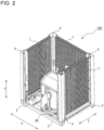
- Fig. 2 is an explanatory view illustrating the internal structure of a lower portion of the heat source unit 100 according to Embodiment 1.
- Fig. 3 is a perspective view illustrating a bottom plate 2 of the heat source unit 100 according to Embodiment 1 in a state in which the bottom plate 2 is supported by support legs 3.
- Fig. 4 is a perspective view illustrating the bottom plate 2 of the heat source unit 100 according to Embodiment 1.
- Fig. 5 is a perspective view illustrating the support leg 3 of the heat source unit 100 according to Embodiment 1.
- Fig. 6 is a cross-sectional view schematically illustrating the structure of an A portion illustrated in Fig. 3 .
- Fig. 7 is an enlarged view of a B portion illustrated in Fig. 6 .
- the heat source unit 100 in the present Embodiment 1 has a housing 1 with its longitudinal direction oriented vertically and having a substantially cuboid shape, a heat exchanger 7 provided along outer sides of the housing 1, and interior constituent components forming a refrigeration cycle, such as a compressor 80, an air-sending fan 81, an accumulator (not illustrated), and a refrigerant pipe (not illustrated) that are installed inside the housing 1.
- a compressor 80 such as a compressor 80, an air-sending fan 81, an accumulator (not illustrated), and a refrigerant pipe (not illustrated) that are installed inside the housing 1.
- the housing 1 includes the bottom plate 2 forming a bottom side of the housing 1, and a pair of support legs 3 configured to support the bottom plate 2.
- the housing 1 further includes four frame materials 4 extending upward (in the Y-direction) from corner portions of the bottom plate 2, front panels 5 covering a front opening, and a fan casing 6 provided surrounding the air-sending fan 81.
- the bottom plate 2 has a substantially rectangular shape, and forms the bottom side of the housing 1.
- the bottom plate 2 is placed on and supported by the pair of support legs 3 at opposite end portions of the bottom plate 2, between which ridge portions 2a and groove portions 2b extend.
- the bottom plate 2 is installed at a predetermined height from an installation surface.
- the bottom plate 2 has a bottom surface that is formed by being bent into a square wave-like shape made up of a series of alternating ridge portions 2a and groove portions 2b.
- the ridge portions 2a and the groove portions 2b are formed individually to have a flat surface and substantially parallel to each other.
- Each of the ridge portions 2a and each of the groove portions 2b are connected by a connecting surface portion 2c.
- the connecting surface portion 2c may be perpendicular to, or inclined to, the ridge portion 2a and the groove portion 2b. That is, the bottom plate 2 may have a bottom surface formed into a rectangular wave-like shape, a trapezoidal wave-like shape, or other shape in cross-section.
- the bottom plate 2 has the bottom surface formed into a wave-like shape, which results in an increase in its rigidity when bending moment is loaded in a planar direction, and accordingly can increase its strength.
- drainage holes 20 are formed through which drain water produced in the heat exchanger 7 and flowing through the bottom surface of the bottom plate 2 is drained to the exterior. Note that an adequate number of drainage holes 20 are formed at proper positions in consideration of the strength of the bottom plate 2 and efficiency in draining the drain water. Note that the positions where the drainage holes 20 are formed, and the number of the drainage holes 20 are not limited to those in the configuration illustrated in Figs. 3 and 4 , and may be appropriately changed depending on the installation location of the heat source unit 100, or the shape, size, and other factors of the bottom plate 2.
- the groove portions 2b are arranged at opposite end portions of the bottom plate 2 in a direction of a series of the alternating ridge portions 2a and groove portions 2b (X-direction).
- flange portions 22 are formed and bent upward from opposite edges of the bottom plate 2 along which these groove portions 2b extend.
- the pair of support legs 3 is located below the bottom plate 2 to support the bottom plate 2.
- the support leg 3 is formed by bending a steel plate, and extends along the direction of a series of the alternating ridge portions 2a and groove portions 2b (X-direction).
- the support leg 3 has a flat installation portion 30 installed on the installation surface of the heat source unit 100, an upright portion 31 extending upward from one edge of the installation portion 30 along its longitudinal direction (X-direction), a support portion 32 bent horizontally from an upper edge of the upright portion 31 along its longitudinal direction (X-direction), and a wall portion 33 extending upward from a tip edge of the support portion 32 along its longitudinal direction (X-direction).
- the support leg 3 is formed into substantially a C-shape in vertical cross-section by the installation portion 30, the upright portion 31, and the support portion 32. Note that the definition of horizontal direction also includes a substantially horizontal direction, and the horizontal direction is not necessarily exactly horizontal.
- the end portion of the bottom plate 2 is placed, and the ridge portions 2a and the groove portions 2b extend to this end portion.
- a lower surface of the groove portions 2b of the bottom plate 2 contacts an upper surface of the support portion 32.
- a positioning mechanism is formed on the bottom plate 2 and the support portions 32 to position the bottom plate 2 and the support portions 32 when the bottom plate 2 is placed on the support portions 32.
- the positioning mechanism has first embosses 21 formed on opposite end portions of the groove portions 2b placed on the support legs 3, and second embosses 34 formed on the support portions 32.
- the first embosses 21 are formed protruding upward from the upper surface of the groove portions 2b.
- a plurality of the first embosses 21 are formed and spaced apart from each other along a direction of a series of wave-like shape.
- the second embosses 34 are formed protruding upward from the upper surface of the support portions 32.
- a plurality of the second embosses 34 are formed along a longitudinal direction of the support portions 32.
- Each of the first embosses 21 and each of the second embosses 34 fit in each other when the bottom plate 2 is placed on the support portions 32.
- Each of the first embosses 21 and each of the second embosses 34 brought into a fit-in state are joined together by a joining part such as a screw from the lower surface of the bottom plate 2.
- a head portion of the joining part is accommodated in a recessed portion of the second emboss 34.
- the heat source unit 100 having the positioning mechanism can facilitate installation of the bottom plate 2 at a predetermined position.
- the positions where the first embosses 21 and the second embosses 34 are formed, and the numbers of the first embosses 21 and the second embosses 34 are not limited to those in the configuration illustrated in Figs. 3 and 4 , and may be appropriately changed depending on the installation location of the heat source unit 100, or the shape, size, and other factors of the bottom plate 2.
- the wall portion 33 is formed such that its wall surface faces the end portion of the bottom plate 2 placed on the support portion 32.
- a connection part 33a of the wall portion 33 and the support portion 32 has a bend R that is formed by bending.
- the wall portion 33 is formed to have a height that is approximately equal to the height of the flange portion 22, and the wall portion 33 along with the flange portion 22 surround the bottom surface.
- air inlets 1a are formed on the left and right sides and the back side of the outer sides surrounded by the frame materials 4, through which air is drawn into the interior of the housing 1.
- a heat exchanger 7 is located along the air inlets 1a.
- the heat exchanger 7 allows refrigerant supplied to the heat exchanger 7 to exchange heat with air passing through the heat exchanger 7.
- the heat exchanger 7 serves as a condenser to condense and liquefy the refrigerant.
- the heat exchanger 7 serves as an evaporator to evaporate and gasify the refrigerant.
- two front panels 5 of decorative sheet metal are provided vertically on the front side of the outer sides surrounded by the frame materials 4.
- the front side of the housing 1 is closed by the front panels 5.
- the front panels 5 are fixed along their left and right side edge portions to the frame materials 4 with fastening parts such as screws.
- the interior constituent components forming the refrigeration cycle are installed, such as the compressor 80 and the accumulator (not illustrated).
- the front panels 5 are removed from the housing 1 to open the interior to the exterior, so that it is possible to perform maintenance on the interior constituent components such as the compressor 80 and the accumulator.
- the air-sending fan 81 is disposed in the housing 1 at a position immediately below the air outlet 1b.
- the air-sending fan 81 is, for example, a propeller fan and is driven by a motor (not illustrated). When this air-sending fan 81 is driven by the motor, air suctioned into the housing 1 from the air inlets 1a passes through the heat exchanger 7 and exchanges heat with refrigerant, and is thereafter discharged from the air outlet 1b via the air-sending fan 81.
- the air-sending fan 81 is surrounded by the fan casing 6 attached to the housing 1.
- the fan casing 6 is located on the outer sides surrounded by the frame materials 4 above the front panels 5 and the heat exchanger 7, and is configured to surround the air-sending fan 81.
- the drain water produced in the heat exchanger 7 flows through the bottom surface of the bottom plate 2, the drain water needs to be drained from the bottom plate 2 to the exterior.
- a clearance is provided between the end portion of the bottom plate 2 and the wall portion 33, and this clearance is used as a drainage channel.
- the clearance serving as the drainage channel is located in vicinity to the bottom of the heat exchanger 7.
- the end portion of the bottom plate 2 is supported on the upper surface of the support portion 32. For this reason, in order that the bottom plate 2 is supported in a stabilized manner, the width of the clearance cannot be increased any further.
- a small width of the clearance prevents a sufficient amount of water from being drained, so that the water is more likely to accumulate in the clearance. For this reason, in a case where the heat source unit 100 is installed in a cold region, water accumulating in the clearance freezes into ice. The ice may grow up to the heat exchanger 7 positioned above the clearance, and is likely to damage the heat exchanger 7.
- the end portion of the bottom plate 2 abuts against a wall surface of the wall portion 33 to close the clearance, and drain water collected on the bottom surface of the bottom plate 2 is drained from the drainage holes 20 formed on the ridge portions 2a and the groove portions 2b of the bottom plate 2.
- the support leg 3 is formed by bending, and the bend R is formed at the corner portion that is the connection part 33a of the support portion 32 and the wall portion 33. Due to this structure, even when the end portion of the bottom plate 2 is attempted to abut against the wall surface of the wall portion 33, the edge of the groove portions 2b abuts against the bend R, which still causes a slight clearance between the bottom plate 2 and the wall portion 33.
- a recessed portion 35 is formed along the longitudinal direction of the support leg 3 (X-direction) on the upper surface of the support portion 32 at the connection part 33a of the wall portion 33 and the support portion 32.
- the recessed portion 35 is formed on the upper surface of the support portion 32 by means of, for example, striking at a portion where the bend R is formed. The striking allows the recessed portion 35 to be formed without increasing the workload during the process of forming the support leg 3. It is thus possible to prevent the increase in manufacturing costs.
- Note that other machining method may also be employed, provided that it is still possible to form the recessed portion 35 on the upper surface of the support portion 32.
- the recessed portion 35 is formed to have a depth greater than the radius of the bend R such that the bend R is completely accommodated in the recessed portion 35.
- the bottom plate 2 is installed in such a manner that its end portion, to which the ridge portions 2a and the groove portions 2b extend, passes over the recessed portion 35 and abuts against the wall surface of the wall portion 33. With this installation, as illustrated in Figs. 6 and 7 , it is possible to close the clearance between the wall portion 33 and the bottom plate 2 which is located in vicinity to the bottom of the heat exchanger 7.
- the heat source unit 100 allows water collected on the bottom surface of the bottom plate 2 to be drained from the drainage holes 20 located away from the heat exchanger 7 without accumulating at the corner portion. It is therefore possible to prevent the heat exchanger 7 from being damaged due to growth of ice.
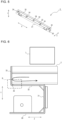
- Fig. 8 is an explanatory view illustrating a modification of the heat source unit 100 according to Embodiment 1.
- a slight clearance may still be possibly made between the end portion of the bottom plate 2 and the wall surface of the wall portion 33 due to dimensional tolerances of the constituent parts.
- a water stop part 36 made of resin material can be used to close the slight clearance between the end portion of the bottom plate 2 and the wall surface of the wall portion 33, as illustrated in Fig. 8 .
- Fig. 9 is an enlarged explanatory view illustrating a relevant part of the heat source unit 100 according to Embodiment 2. Note that the same constituent elements as those of the heat source unit 100 described in Embodiment 1 are denoted by the same reference signs, and descriptions thereof are appropriately omitted.
- the recessed portion 35 is formed on the upper surface of the support portion 32 at the connection part 33a of the wall portion 33 and the support portion 32.
- the bottom plate 2 is installed in such a manner that its end portion, to which the ridge portions 2a and the groove portions 2b extend, passes over the recessed portion 35 and abuts against the wall surface of the wall portion 33.
- a slight clearance may possibly be made between the end portion of the bottom plate 2 and the wall surface of the wall portion 33 due to the dimensional tolerances of the constituent parts. Due to this structure, drain water may enter the recessed portion 35 from this slight clearance, and then may possibly freeze into ice in the recessed portion 35.
- a through hole 37 communicating with the exterior is formed at the recessed portion 35, as illustrated in Fig. 9 .
- the through hole 37 is provided to drain the water having entered the recessed portion 35 to the exterior.
- a plurality of the through holes 37 are formed and spaced apart from each other along the longitudinal direction of the support leg 3 (X-direction).
- the size and shape of the through holes 37 are appropriately changed depending on the installation location of the heat source unit 100, or the shape, size, and other factors of the bottom plate 2.
- the recessed portion 35 may have an inclined bottom surface, or may be provided with a part that guides the water to the through holes 37.
- the through holes 37 communicating with the exterior are formed at the recessed portion 35. Consequently, even if water may enter the recessed portion 35 from the slight clearance between the end portion of the bottom plate 2 and the wall surface of the wall portion 33, it is still possible to drain the water through the through holes 37 to the exterior.
- the heat source unit 100 has been described above based on the embodiments, the heat source unit 100 is not limited to having the configuration in the above embodiments.
- the configuration of the heat source unit 100 described above is merely an example, and may include other constituent elements or may omit some of the constituent elements.
- the heat source unit 100 includes design modifications and application variations that are usually made by those skilled in the art without departing from the scope of the technical concept.
Landscapes
- Engineering & Computer Science (AREA)
- Chemical & Material Sciences (AREA)
- Combustion & Propulsion (AREA)
- Mechanical Engineering (AREA)
- General Engineering & Computer Science (AREA)
- Other Air-Conditioning Systems (AREA)
- Arrangement Of Elements, Cooling, Sealing, Or The Like Of Lighting Devices (AREA)
- Cookers (AREA)
- Resistance Heating (AREA)
Abstract
Description
- The present disclosure relates to a heat source unit to be installed outdoors.
- A heat source unit, which is a part of an air-conditioning apparatus or other apparatus, has been conventionally known as being installed outdoors. A heat source unit disclosed in Patent Literature 1 has a casing with a substantially cuboid box shape, a heat source side fan, and constituent components of a refrigerant circuit, including a compressor and a heat source side heat exchanger. The casing has a bottom frame with a wave-like shape made up of a series of alternating ridge portions and groove portions, and a pair of fixing legs located at opposite end portions of the bottom frame, between which the ridge portions and groove portions extend, and configured to support the opposite end portions. Each of the fixing legs has a support portion on which the end portion of the bottom frame is placed, and a wall portion extending upward from the support portion. The wall portion is formed such that its wall surface faces the end portion of the bottom frame placed on the support portion. Between the end portion of the ridge portions of the bottom frame and the wall portion of the fixing leg, there is a clearance to serve as a drainage channel through which water running on an upper surface of the ridge portions flows to the support portion.
- Patent Literature 1:
Japanese Patent Publication No. 6361685 - However, since the heat source unit disclosed in Patent Literature 1 has a heat exchanger located along an outer peripheral edge of the bottom plate, the clearance serving as the drainage channel is located in vicinity to the bottom of the heat exchanger. In addition, the end portion of the bottom frame is supported on the upper surface of the support portion. For this reason, in order that the bottom frame is supported in a stabilized manner, the width of the clearance cannot be increased any further. However, a small width of the clearance prevents a sufficient amount of water from being drained, so that the water is more likely to accumulate in this clearance. For this reason, in a case where the heat source unit is installed in a cold region, water accumulating in the clearance freezes into ice. The ice may grow up to the heat exchanger positioned above the clearance, and is likely to damage the heat exchanger.
- The present disclosure has been made to solve the above problems, and it is an object of the present disclosure to provide a heat source unit in which water collected on a bottom surface of a bottom plate is drained from drainage holes located away from a heat exchanger, so that it is possible to prevent the heat exchanger from being damaged due to growth of ice.
- A heat source unit according to an embodiment of the present disclosure includes: a bottom plate having a wave-like shape made up of a series of alternating ridge portions and groove portions; and a pair of support legs located at opposite end portions of the bottom plate, between which the ridge portions and groove portions extend, the pair of support legs being configured to support the opposite end portions, wherein each of the support legs has a support portion on which an end portion of the bottom plate is placed, and a wall portion extending upward from the support portion, on an upper surface of the support portion, a recessed portion is formed at a connection part of the wall portion and the support portion, and the bottom plate is installed in such a manner that an end portion of the bottom plate, to which the ridge portions and groove portions extend, passes over the recessed portion and abuts against a wall surface of the wall portion.
- According to an embodiment of the present disclosure, the recessed portion is formed on the upper surface of the support portion at the connection part of the wall portion and the support portion, and the bottom plate is installed in such a manner that the end portion of the bottom plate, to which the ridge portions and groove portions extend, passes over the recessed portion and abuts against the wall surface of the wall portion. It is thus possible to close a clearance between the end portion of the bottom plate and the wall surface of the wall portion. Consequently, water collected on the bottom surface of the bottom plate can be drained from the drainage holes located away from the heat exchanger without accumulating at the corner portion. It is therefore possible to prevent the heat exchanger from being damaged due to growth of ice.
-
- [
Fig. 1] Fig. 1 is a perspective view illustrating the external appearance of a heat source unit according to Embodiment 1. - [
Fig. 2] Fig. 2 is an explanatory view illustrating the internal structure of a lower portion of the heat source unit according to Embodiment 1. - [
Fig. 3] Fig. 3 is a perspective view illustrating a bottom plate of the heat source unit according to Embodiment 1 in a state in which the bottom plate is supported by support legs. - [
Fig. 4] Fig. 4 is a perspective view illustrating the bottom plate of the heat source unit according to Embodiment 1. - [
Fig. 5] Fig. 5 is a perspective view illustrating the support leg of the heat source unit according to Embodiment 1. - [
Fig. 6] Fig. 6 is a cross-sectional view schematically illustrating the structure of an A portion illustrated inFig. 3 . - [
Fig. 7] Fig. 7 is an enlarged view of a B portion illustrated inFig. 6 . - [
Fig. 8] Fig. 8 is an explanatory view illustrating a modification of the heat source unit according to Embodiment 1. - [
Fig. 9] Fig. 9 is an enlarged explanatory view illustrating a relevant part of the heat source unit according toEmbodiment 2. - Hereinafter, an embodiment of the present disclosure will be described with reference to the drawings. Note that in the drawings, the same or equivalent parts will be denoted by the same reference numerals, and descriptions thereof will be appropriately omitted or simplified. The shape, size, location, and other factors of the constituent components described in the drawings may be appropriately changed.
-
Fig. 1 is a perspective view illustrating the external appearance of aheat source unit 100 according to Embodiment 1.Fig. 2 is an explanatory view illustrating the internal structure of a lower portion of theheat source unit 100 according to Embodiment 1.Fig. 3 is a perspective view illustrating abottom plate 2 of theheat source unit 100 according to Embodiment 1 in a state in which thebottom plate 2 is supported bysupport legs 3.Fig. 4 is a perspective view illustrating thebottom plate 2 of theheat source unit 100 according to Embodiment 1.Fig. 5 is a perspective view illustrating thesupport leg 3 of theheat source unit 100 according to Embodiment 1.Fig. 6 is a cross-sectional view schematically illustrating the structure of an A portion illustrated inFig. 3 .Fig. 7 is an enlarged view of a B portion illustrated inFig. 6 . - As illustrated in
Figs. 1 and2 , theheat source unit 100 in the present Embodiment 1 has a housing 1 with its longitudinal direction oriented vertically and having a substantially cuboid shape, a heat exchanger 7 provided along outer sides of the housing 1, and interior constituent components forming a refrigeration cycle, such as acompressor 80, an air-sending fan 81, an accumulator (not illustrated), and a refrigerant pipe (not illustrated) that are installed inside the housing 1. - As illustrated in
Fig. 1 , the housing 1 includes thebottom plate 2 forming a bottom side of the housing 1, and a pair ofsupport legs 3 configured to support thebottom plate 2. The housing 1 further includes fourframe materials 4 extending upward (in the Y-direction) from corner portions of thebottom plate 2,front panels 5 covering a front opening, and a fan casing 6 provided surrounding the air-sendingfan 81. - As illustrated in
Figs. 3 and 4 , thebottom plate 2 has a substantially rectangular shape, and forms the bottom side of the housing 1. Thebottom plate 2 is placed on and supported by the pair ofsupport legs 3 at opposite end portions of thebottom plate 2, between whichridge portions 2a andgroove portions 2b extend. Thebottom plate 2 is installed at a predetermined height from an installation surface. On a top surface of thebottom plate 2, the interior constituent components such as thecompressor 80 are placed. Thebottom plate 2 has a bottom surface that is formed by being bent into a square wave-like shape made up of a series ofalternating ridge portions 2a andgroove portions 2b. Theridge portions 2a and thegroove portions 2b are formed individually to have a flat surface and substantially parallel to each other. Each of theridge portions 2a and each of thegroove portions 2b are connected by a connectingsurface portion 2c. The connectingsurface portion 2c may be perpendicular to, or inclined to, theridge portion 2a and thegroove portion 2b. That is, thebottom plate 2 may have a bottom surface formed into a rectangular wave-like shape, a trapezoidal wave-like shape, or other shape in cross-section. Thebottom plate 2 has the bottom surface formed into a wave-like shape, which results in an increase in its rigidity when bending moment is loaded in a planar direction, and accordingly can increase its strength. - On the
ridge portions 2a and thegroove portions 2b,drainage holes 20 are formed through which drain water produced in the heat exchanger 7 and flowing through the bottom surface of thebottom plate 2 is drained to the exterior. Note that an adequate number ofdrainage holes 20 are formed at proper positions in consideration of the strength of thebottom plate 2 and efficiency in draining the drain water. Note that the positions where thedrainage holes 20 are formed, and the number of thedrainage holes 20 are not limited to those in the configuration illustrated inFigs. 3 and 4 , and may be appropriately changed depending on the installation location of theheat source unit 100, or the shape, size, and other factors of thebottom plate 2. - The
groove portions 2b are arranged at opposite end portions of thebottom plate 2 in a direction of a series of thealternating ridge portions 2a andgroove portions 2b (X-direction). On thegroove portions 2b positioned at opposite end portions of thebottom plate 2,flange portions 22 are formed and bent upward from opposite edges of thebottom plate 2 along which thesegroove portions 2b extend. - As illustrated in
Figs. 1 to 3 , the pair ofsupport legs 3 is located below thebottom plate 2 to support thebottom plate 2. Thesupport leg 3 is formed by bending a steel plate, and extends along the direction of a series of the alternatingridge portions 2a andgroove portions 2b (X-direction). As illustrated inFigs. 5 and 6 , thesupport leg 3 has aflat installation portion 30 installed on the installation surface of theheat source unit 100, anupright portion 31 extending upward from one edge of theinstallation portion 30 along its longitudinal direction (X-direction), asupport portion 32 bent horizontally from an upper edge of theupright portion 31 along its longitudinal direction (X-direction), and awall portion 33 extending upward from a tip edge of thesupport portion 32 along its longitudinal direction (X-direction). Thesupport leg 3 is formed into substantially a C-shape in vertical cross-section by theinstallation portion 30, theupright portion 31, and thesupport portion 32. Note that the definition of horizontal direction also includes a substantially horizontal direction, and the horizontal direction is not necessarily exactly horizontal. - On the
support portion 32, the end portion of thebottom plate 2 is placed, and theridge portions 2a and thegroove portions 2b extend to this end portion. A lower surface of thegroove portions 2b of thebottom plate 2 contacts an upper surface of thesupport portion 32. A positioning mechanism is formed on thebottom plate 2 and thesupport portions 32 to position thebottom plate 2 and thesupport portions 32 when thebottom plate 2 is placed on thesupport portions 32. The positioning mechanism has first embosses 21 formed on opposite end portions of thegroove portions 2b placed on thesupport legs 3, and second embosses 34 formed on thesupport portions 32. The first embosses 21 are formed protruding upward from the upper surface of thegroove portions 2b. A plurality of the first embosses 21 are formed and spaced apart from each other along a direction of a series of wave-like shape. The second embosses 34 are formed protruding upward from the upper surface of thesupport portions 32. A plurality of the second embosses 34 are formed along a longitudinal direction of thesupport portions 32. Each of the first embosses 21 and each of the second embosses 34 fit in each other when thebottom plate 2 is placed on thesupport portions 32. Each of the first embosses 21 and each of the second embosses 34 brought into a fit-in state are joined together by a joining part such as a screw from the lower surface of thebottom plate 2. A head portion of the joining part is accommodated in a recessed portion of thesecond emboss 34. Theheat source unit 100 having the positioning mechanism can facilitate installation of thebottom plate 2 at a predetermined position. Note that the positions where the first embosses 21 and the second embosses 34 are formed, and the numbers of the first embosses 21 and the second embosses 34 are not limited to those in the configuration illustrated inFigs. 3 and 4 , and may be appropriately changed depending on the installation location of theheat source unit 100, or the shape, size, and other factors of thebottom plate 2. - The
wall portion 33 is formed such that its wall surface faces the end portion of thebottom plate 2 placed on thesupport portion 32. Aconnection part 33a of thewall portion 33 and thesupport portion 32 has a bend R that is formed by bending. As illustrated inFig. 3 , thewall portion 33 is formed to have a height that is approximately equal to the height of theflange portion 22, and thewall portion 33 along with theflange portion 22 surround the bottom surface. - Next, other constituent components of the housing 1 are described. In the housing 1, as illustrated in
Figs. 1 and2 ,air inlets 1a are formed on the left and right sides and the back side of the outer sides surrounded by theframe materials 4, through which air is drawn into the interior of the housing 1. A heat exchanger 7 is located along theair inlets 1a. The heat exchanger 7 allows refrigerant supplied to the heat exchanger 7 to exchange heat with air passing through the heat exchanger 7. During cooling operation, the heat exchanger 7 serves as a condenser to condense and liquefy the refrigerant. In contrast, during heating operation, the heat exchanger 7 serves as an evaporator to evaporate and gasify the refrigerant. - In the housing 1, as illustrated in
Fig. 1 , twofront panels 5 of decorative sheet metal are provided vertically on the front side of the outer sides surrounded by theframe materials 4. The front side of the housing 1 is closed by thefront panels 5. Thefront panels 5 are fixed along their left and right side edge portions to theframe materials 4 with fastening parts such as screws. As illustrated inFig. 2 , in the lower interior of the housing 1, the interior constituent components forming the refrigeration cycle are installed, such as thecompressor 80 and the accumulator (not illustrated). In theheat source unit 100, thefront panels 5 are removed from the housing 1 to open the interior to the exterior, so that it is possible to perform maintenance on the interior constituent components such as thecompressor 80 and the accumulator. - On the top side of the housing 1, an
air outlet 1b is formed. The air-sendingfan 81 is disposed in the housing 1 at a position immediately below theair outlet 1b. The air-sendingfan 81 is, for example, a propeller fan and is driven by a motor (not illustrated). When this air-sendingfan 81 is driven by the motor, air suctioned into the housing 1 from theair inlets 1a passes through the heat exchanger 7 and exchanges heat with refrigerant, and is thereafter discharged from theair outlet 1b via the air-sendingfan 81. The air-sendingfan 81 is surrounded by the fan casing 6 attached to the housing 1. The fan casing 6 is located on the outer sides surrounded by theframe materials 4 above thefront panels 5 and the heat exchanger 7, and is configured to surround the air-sendingfan 81. - In the
heat source unit 100, since drain water produced in the heat exchanger 7 flows through the bottom surface of thebottom plate 2, the drain water needs to be drained from thebottom plate 2 to the exterior. For example, it is conceivable that a clearance is provided between the end portion of thebottom plate 2 and thewall portion 33, and this clearance is used as a drainage channel. However, since the heat exchanger 7 is located along an outer peripheral edge of thebottom plate 2, the clearance serving as the drainage channel is located in vicinity to the bottom of the heat exchanger 7. In addition, the end portion of thebottom plate 2 is supported on the upper surface of thesupport portion 32. For this reason, in order that thebottom plate 2 is supported in a stabilized manner, the width of the clearance cannot be increased any further. However, a small width of the clearance prevents a sufficient amount of water from being drained, so that the water is more likely to accumulate in the clearance. For this reason, in a case where theheat source unit 100 is installed in a cold region, water accumulating in the clearance freezes into ice. The ice may grow up to the heat exchanger 7 positioned above the clearance, and is likely to damage the heat exchanger 7. - It is therefore desirable that the end portion of the
bottom plate 2 abuts against a wall surface of thewall portion 33 to close the clearance, and drain water collected on the bottom surface of thebottom plate 2 is drained from the drainage holes 20 formed on theridge portions 2a and thegroove portions 2b of thebottom plate 2. However, thesupport leg 3 is formed by bending, and the bend R is formed at the corner portion that is theconnection part 33a of thesupport portion 32 and thewall portion 33. Due to this structure, even when the end portion of thebottom plate 2 is attempted to abut against the wall surface of thewall portion 33, the edge of thegroove portions 2b abuts against the bend R, which still causes a slight clearance between thebottom plate 2 and thewall portion 33. - In view of that, in the
heat source unit 100 according to the present Embodiment 1, as illustrated inFigs. 6 and7 , a recessedportion 35 is formed along the longitudinal direction of the support leg 3 (X-direction) on the upper surface of thesupport portion 32 at theconnection part 33a of thewall portion 33 and thesupport portion 32. Specifically, the recessedportion 35 is formed on the upper surface of thesupport portion 32 by means of, for example, striking at a portion where the bend R is formed. The striking allows the recessedportion 35 to be formed without increasing the workload during the process of forming thesupport leg 3. It is thus possible to prevent the increase in manufacturing costs. Note that other machining method may also be employed, provided that it is still possible to form the recessedportion 35 on the upper surface of thesupport portion 32. The recessedportion 35 is formed to have a depth greater than the radius of the bend R such that the bend R is completely accommodated in the recessedportion 35. Thebottom plate 2 is installed in such a manner that its end portion, to which theridge portions 2a and thegroove portions 2b extend, passes over the recessedportion 35 and abuts against the wall surface of thewall portion 33. With this installation, as illustrated inFigs. 6 and7 , it is possible to close the clearance between thewall portion 33 and thebottom plate 2 which is located in vicinity to the bottom of the heat exchanger 7. Since the clearance between thebottom plate 2 and thewall portion 33 is closed, drain water flowing through, and collected on, the bottom surface of thebottom plate 2 hits the wall surface of thewall portion 33 and is then guided to the drainage holes 20 formed on thebottom plate 2 as illustrated by the arrow inFig. 6 . Consequently, theheat source unit 100 according to the present Embodiment 1 allows water collected on the bottom surface of thebottom plate 2 to be drained from the drainage holes 20 located away from the heat exchanger 7 without accumulating at the corner portion. It is therefore possible to prevent the heat exchanger 7 from being damaged due to growth of ice. -
Fig. 8 is an explanatory view illustrating a modification of theheat source unit 100 according to Embodiment 1. In theheat source unit 100 according to the present Embodiment 1, even when thebottom plate 2 is installed in such a manner that the end portion of thebottom plate 2, to which theridge portions 2a and thegroove portions 2b extend, passes over the recessedportion 35 and abuts against the wall surface of thewall portion 33, a slight clearance may still be possibly made between the end portion of thebottom plate 2 and the wall surface of thewall portion 33 due to dimensional tolerances of the constituent parts. In that case, awater stop part 36 made of resin material can be used to close the slight clearance between the end portion of thebottom plate 2 and the wall surface of thewall portion 33, as illustrated inFig. 8 . This allows the clearance between the end portion of thebottom plate 2 and the wall surface of thewall portion 33 to be completely closed, and can accordingly improve the above functional effect. However, it is allowable that thewater stop part 36 is not necessarily provided. Even in this case where thewater stop part 36 is not provided, the above effect can still be sufficiently achieved. - Next, the
heat source unit 100 according to thepresent Embodiment 2 is described with reference toFig. 9. Fig. 9 is an enlarged explanatory view illustrating a relevant part of theheat source unit 100 according toEmbodiment 2. Note that the same constituent elements as those of theheat source unit 100 described in Embodiment 1 are denoted by the same reference signs, and descriptions thereof are appropriately omitted. - As described above, also in the
heat source unit 100 according to thepresent Embodiment 2, the recessedportion 35 is formed on the upper surface of thesupport portion 32 at theconnection part 33a of thewall portion 33 and thesupport portion 32. Thebottom plate 2 is installed in such a manner that its end portion, to which theridge portions 2a and thegroove portions 2b extend, passes over the recessedportion 35 and abuts against the wall surface of thewall portion 33. However, as described above, a slight clearance may possibly be made between the end portion of thebottom plate 2 and the wall surface of thewall portion 33 due to the dimensional tolerances of the constituent parts. Due to this structure, drain water may enter the recessedportion 35 from this slight clearance, and then may possibly freeze into ice in the recessedportion 35. - In view of the above, in the
heat source unit 100 according to thepresent Embodiment 2, a throughhole 37 communicating with the exterior is formed at the recessedportion 35, as illustrated inFig. 9 . The throughhole 37 is provided to drain the water having entered the recessedportion 35 to the exterior. A plurality of the throughholes 37 are formed and spaced apart from each other along the longitudinal direction of the support leg 3 (X-direction). The size and shape of the throughholes 37 are appropriately changed depending on the installation location of theheat source unit 100, or the shape, size, and other factors of thebottom plate 2. Note that, to improve the efficiency in draining water from the throughholes 37, the recessedportion 35 may have an inclined bottom surface, or may be provided with a part that guides the water to the through holes 37. - As described above, in the
heat source unit 100 according to thepresent Embodiment 2, the throughholes 37 communicating with the exterior are formed at the recessedportion 35. Consequently, even if water may enter the recessedportion 35 from the slight clearance between the end portion of thebottom plate 2 and the wall surface of thewall portion 33, it is still possible to drain the water through the throughholes 37 to the exterior. - While the
heat source unit 100 has been described above based on the embodiments, theheat source unit 100 is not limited to having the configuration in the above embodiments. The configuration of theheat source unit 100 described above is merely an example, and may include other constituent elements or may omit some of the constituent elements. To sum up, theheat source unit 100 includes design modifications and application variations that are usually made by those skilled in the art without departing from the scope of the technical concept. - 1: housing, 1a: air inlet, 1b: air outlet, 2: bottom plate, 2a: ridge portion, 2b: groove portion, 2c: connecting surface portion, 3: support leg, 4: frame material, 5: front panel, 6: fan casing, 7: heat exchanger, 20: drainage hole, 21: first emboss, 22: flange portion, 30: installation portion, 31: upright portion, 32: support portion, 33: wall portion, 33a: connection part, 34: second emboss, 35: recessed portion, 36: water stop part, 37: through hole, 80: compressor, 81: air-sending fan, 100: heat source unit
Claims (4)
- A heat source unit comprising: a bottom plate having a wave-like shape made up of a series of alternating ridge portions and groove portions; anda pair of support legs located at opposite end portions of the bottom plate, between which the ridge portions and groove portions extend, the pair of support legs being configured to support the opposite end portions, whereineach of the support legs has a support portion on which an end portion of the bottom plate is placed, and a wall portion extending upward from the support portion,on an upper surface of the support portion, a recessed portion is formed at a connection part of the wall portion and the support portion, andthe bottom plate is installed in such a manner that an end portion of the bottom plate, to which the ridge portions and groove portions extend, passes over the recessed portion and abuts against a wall surface of the wall portion.
- The heat source unit of claim 1, wherein a positioning mechanism is formed on the bottom plate and the support portion to position the bottom plate and the support portion when the bottom plate is placed on the support portion.
- The heat source unit of claim 1 or 2, wherein a water stop part is provided at a portion where the wall surface of the wall portion and an end portion of the bottom plate, to which the ridge portions and groove portions extend, abut against each other.
- The heat source unit of claim 1 or 2, wherein a through hole communicating with an exterior of the bottom plate is formed at the recessed portion.
Applications Claiming Priority (1)
| Application Number | Priority Date | Filing Date | Title |
|---|---|---|---|
| PCT/JP2022/018665 WO2023209753A1 (en) | 2022-04-25 | 2022-04-25 | Heat source unit |
Publications (2)
| Publication Number | Publication Date |
|---|---|
| EP4517199A1 true EP4517199A1 (en) | 2025-03-05 |
| EP4517199A4 EP4517199A4 (en) | 2025-06-11 |
Family
ID=88518066
Family Applications (1)
| Application Number | Title | Priority Date | Filing Date |
|---|---|---|---|
| EP22940034.6A Pending EP4517199A4 (en) | 2022-04-25 | 2022-04-25 | HEAT SOURCE UNIT |
Country Status (5)
| Country | Link |
|---|---|
| US (1) | US20250155157A1 (en) |
| EP (1) | EP4517199A4 (en) |
| JP (1) | JP7646081B2 (en) |
| CN (1) | CN119032240A (en) |
| WO (1) | WO2023209753A1 (en) |
Families Citing this family (1)
| Publication number | Priority date | Publication date | Assignee | Title |
|---|---|---|---|---|
| JPWO2025109641A1 (en) * | 2023-11-20 | 2025-05-30 |
Family Cites Families (18)
| Publication number | Priority date | Publication date | Assignee | Title |
|---|---|---|---|---|
| JPS561717U (en) * | 1979-06-13 | 1981-01-09 | ||
| DE502006005868D1 (en) * | 2005-08-19 | 2010-02-25 | Freudenberg Carl Kg | HUMIDIFIERS |
| JP5420441B2 (en) * | 2010-01-29 | 2014-02-19 | 三洋電機株式会社 | Air conditioner outdoor unit |
| DE202012010569U1 (en) * | 2012-11-07 | 2013-01-15 | Berliner Wartungs- und Kundendienst GmbH | Housing or chamber for receiving filters, heat exchangers, humidifiers, evaporators, air conditioners, fans, blower and suction devices and lightweight wall for repairing such housing |
| JP2014219166A (en) * | 2013-05-09 | 2014-11-20 | ダイキン工業株式会社 | Air conditioner outdoor unit |
| JP6252392B2 (en) * | 2014-07-23 | 2017-12-27 | 三菱電機株式会社 | Air conditioner indoor unit |
| KR20160031230A (en) * | 2014-09-12 | 2016-03-22 | 엘지전자 주식회사 | An outdoor unit for a an air conditioner |
| US10208968B2 (en) * | 2014-12-26 | 2019-02-19 | Mitsubishi Electric Corporation | Outdoor unit |
| JP6361685B2 (en) | 2016-04-21 | 2018-07-25 | ダイキン工業株式会社 | Heat source unit |
| JP6269717B2 (en) * | 2016-04-21 | 2018-01-31 | ダイキン工業株式会社 | Heat source unit |
| WO2018011939A1 (en) * | 2016-07-14 | 2018-01-18 | 三菱電機株式会社 | Outdoor unit of air conditioner |
| US10448736B2 (en) * | 2016-08-17 | 2019-10-22 | Belintra, Inc. | Washable mobile cabinet with drainage |
| EP3505836A4 (en) * | 2016-08-23 | 2019-07-31 | GD Midea Heating & Ventilating Equipment Co., Ltd. | SWITCHING DEVICE FOR MULTI-DIVISION AIR CONDITIONER AND MULTI-DIVISION AIR CONDITIONER HAVING THE SAME |
| WO2018225224A1 (en) * | 2017-06-08 | 2018-12-13 | 三菱電機株式会社 | Heat exchanging ventilation device |
| JP6936160B2 (en) * | 2018-01-31 | 2021-09-15 | ダイキン工業株式会社 | Outdoor unit of air conditioner |
| JP6610691B2 (en) * | 2018-03-13 | 2019-11-27 | ダイキン工業株式会社 | Heat source unit |
| KR102857859B1 (en) * | 2020-08-10 | 2025-09-10 | 삼성전자주식회사 | Outdoor unit of air conditioner |
| JP7235994B2 (en) * | 2021-06-29 | 2023-03-09 | ダイキン工業株式会社 | Ventilators and methods of assembling the ventilators |
-
2022
- 2022-04-25 US US18/838,453 patent/US20250155157A1/en active Pending
- 2022-04-25 WO PCT/JP2022/018665 patent/WO2023209753A1/en not_active Ceased
- 2022-04-25 EP EP22940034.6A patent/EP4517199A4/en active Pending
- 2022-04-25 JP JP2024517612A patent/JP7646081B2/en active Active
- 2022-04-25 CN CN202280091937.7A patent/CN119032240A/en active Pending
Also Published As
| Publication number | Publication date |
|---|---|
| JPWO2023209753A1 (en) | 2023-11-02 |
| US20250155157A1 (en) | 2025-05-15 |
| CN119032240A (en) | 2024-11-26 |
| EP4517199A4 (en) | 2025-06-11 |
| WO2023209753A1 (en) | 2023-11-02 |
| JP7646081B2 (en) | 2025-03-14 |
Similar Documents
| Publication | Publication Date | Title |
|---|---|---|
| KR101439813B1 (en) | Outdoor unit for air conditioner | |
| CN103946640B (en) | Embedded air conditioner | |
| JP5420441B2 (en) | Air conditioner outdoor unit | |
| US20140298844A1 (en) | Heater and an outdoor unit including the same for a refrigerator | |
| CN102141272B (en) | Outdoor unit for air conditioner | |
| KR20160084225A (en) | Outdoor unit of air conditioner and manufacture method | |
| EP4517199A1 (en) | Heat source unit | |
| EP4715278A1 (en) | Air conditioner chassis structure, air conditioner outdoor unit, and air conditioner | |
| KR102326299B1 (en) | Indoor unit for air conditoiner | |
| CN214501434U (en) | Indoor unit of air conditioner | |
| CN214501457U (en) | Indoor unit of air conditioner | |
| CN214501423U (en) | Indoor unit of air conditioner | |
| KR100794354B1 (en) | Air conditioner | |
| CN221055124U (en) | Ceiling air conditioner | |
| CN215336758U (en) | Outdoor machine of air conditioner | |
| CN214501443U (en) | Indoor unit of air conditioner | |
| CN214501435U (en) | Indoor unit of air conditioner | |
| JP7402029B2 (en) | heat source machine | |
| JP2014043977A (en) | Outdoor equipment of freezer | |
| JP4553534B2 (en) | Cooling unit | |
| JP7397632B2 (en) | Heat source machine, manufacturing method of heat source machine | |
| JP4632605B2 (en) | Cooling unit | |
| KR100794352B1 (en) | Air conditioner | |
| EP3492833A1 (en) | Refrigerating cycle device | |
| EP4650685A1 (en) | Outdoor unit of refrigeration cycle device |
Legal Events
| Date | Code | Title | Description |
|---|---|---|---|
| STAA | Information on the status of an ep patent application or granted ep patent |
Free format text: STATUS: THE INTERNATIONAL PUBLICATION HAS BEEN MADE |
|
| PUAI | Public reference made under article 153(3) epc to a published international application that has entered the european phase |
Free format text: ORIGINAL CODE: 0009012 |
|
| STAA | Information on the status of an ep patent application or granted ep patent |
Free format text: STATUS: REQUEST FOR EXAMINATION WAS MADE |
|
| 17P | Request for examination filed |
Effective date: 20241017 |
|
| AK | Designated contracting states |
Kind code of ref document: A1 Designated state(s): AL AT BE BG CH CY CZ DE DK EE ES FI FR GB GR HR HU IE IS IT LI LT LU LV MC MK MT NL NO PL PT RO RS SE SI SK SM TR |
|
| A4 | Supplementary search report drawn up and despatched |
Effective date: 20250513 |
|
| RIC1 | Information provided on ipc code assigned before grant |
Ipc: F24F 1/56 20110101AFI20250508BHEP |
|
| DAV | Request for validation of the european patent (deleted) | ||
| DAX | Request for extension of the european patent (deleted) |