EP4517197A1 - Air conditioner with controlled louver arrangement - Google Patents
Air conditioner with controlled louver arrangement Download PDFInfo
- Publication number
- EP4517197A1 EP4517197A1 EP24184854.8A EP24184854A EP4517197A1 EP 4517197 A1 EP4517197 A1 EP 4517197A1 EP 24184854 A EP24184854 A EP 24184854A EP 4517197 A1 EP4517197 A1 EP 4517197A1
- Authority
- EP
- European Patent Office
- Prior art keywords
- louver
- air
- drive
- air conditioner
- louvers
- Prior art date
- Legal status (The legal status is an assumption and is not a legal conclusion. Google has not performed a legal analysis and makes no representation as to the accuracy of the status listed.)
- Pending
Links
Images


Classifications
-
- F—MECHANICAL ENGINEERING; LIGHTING; HEATING; WEAPONS; BLASTING
- F24—HEATING; RANGES; VENTILATING
- F24F—AIR-CONDITIONING; AIR-HUMIDIFICATION; VENTILATION; USE OF AIR CURRENTS FOR SCREENING
- F24F1/00—Room units for air-conditioning, e.g. separate or self-contained units or units receiving primary air from a central station
- F24F1/0007—Indoor units, e.g. fan coil units
- F24F1/0011—Indoor units, e.g. fan coil units characterised by air outlets
-
- F—MECHANICAL ENGINEERING; LIGHTING; HEATING; WEAPONS; BLASTING
- F24—HEATING; RANGES; VENTILATING
- F24F—AIR-CONDITIONING; AIR-HUMIDIFICATION; VENTILATION; USE OF AIR CURRENTS FOR SCREENING
- F24F1/00—Room units for air-conditioning, e.g. separate or self-contained units or units receiving primary air from a central station
- F24F1/0007—Indoor units, e.g. fan coil units
- F24F1/0071—Indoor units, e.g. fan coil units with means for purifying supplied air
-
- F—MECHANICAL ENGINEERING; LIGHTING; HEATING; WEAPONS; BLASTING
- F24—HEATING; RANGES; VENTILATING
- F24F—AIR-CONDITIONING; AIR-HUMIDIFICATION; VENTILATION; USE OF AIR CURRENTS FOR SCREENING
- F24F1/00—Room units for air-conditioning, e.g. separate or self-contained units or units receiving primary air from a central station
- F24F1/02—Self-contained room units for air-conditioning, i.e. with all apparatus for treatment installed in a common casing
-
- F—MECHANICAL ENGINEERING; LIGHTING; HEATING; WEAPONS; BLASTING
- F24—HEATING; RANGES; VENTILATING
- F24F—AIR-CONDITIONING; AIR-HUMIDIFICATION; VENTILATION; USE OF AIR CURRENTS FOR SCREENING
- F24F1/00—Room units for air-conditioning, e.g. separate or self-contained units or units receiving primary air from a central station
- F24F1/02—Self-contained room units for air-conditioning, i.e. with all apparatus for treatment installed in a common casing
- F24F1/0328—Self-contained room units for air-conditioning, i.e. with all apparatus for treatment installed in a common casing with means for purifying supplied air
-
- F—MECHANICAL ENGINEERING; LIGHTING; HEATING; WEAPONS; BLASTING
- F24—HEATING; RANGES; VENTILATING
- F24F—AIR-CONDITIONING; AIR-HUMIDIFICATION; VENTILATION; USE OF AIR CURRENTS FOR SCREENING
- F24F11/00—Control or safety arrangements
- F24F11/70—Control systems characterised by their outputs; Constructional details thereof
- F24F11/72—Control systems characterised by their outputs; Constructional details thereof for controlling the supply of treated air, e.g. its pressure
- F24F11/79—Control systems characterised by their outputs; Constructional details thereof for controlling the supply of treated air, e.g. its pressure for controlling the direction of the supplied air
-
- F—MECHANICAL ENGINEERING; LIGHTING; HEATING; WEAPONS; BLASTING
- F24—HEATING; RANGES; VENTILATING
- F24F—AIR-CONDITIONING; AIR-HUMIDIFICATION; VENTILATION; USE OF AIR CURRENTS FOR SCREENING
- F24F13/00—Details common to, or for air-conditioning, air-humidification, ventilation or use of air currents for screening
- F24F13/08—Air-flow control members, e.g. louvres, grilles, flaps or guide plates
- F24F13/10—Air-flow control members, e.g. louvres, grilles, flaps or guide plates movable, e.g. dampers
- F24F13/14—Air-flow control members, e.g. louvres, grilles, flaps or guide plates movable, e.g. dampers built up of tilting members, e.g. louvre
- F24F13/1413—Air-flow control members, e.g. louvres, grilles, flaps or guide plates movable, e.g. dampers built up of tilting members, e.g. louvre using more than one tilting member, e.g. with several pivoting blades
-
- F—MECHANICAL ENGINEERING; LIGHTING; HEATING; WEAPONS; BLASTING
- F24—HEATING; RANGES; VENTILATING
- F24F—AIR-CONDITIONING; AIR-HUMIDIFICATION; VENTILATION; USE OF AIR CURRENTS FOR SCREENING
- F24F13/00—Details common to, or for air-conditioning, air-humidification, ventilation or use of air currents for screening
- F24F13/08—Air-flow control members, e.g. louvres, grilles, flaps or guide plates
- F24F13/10—Air-flow control members, e.g. louvres, grilles, flaps or guide plates movable, e.g. dampers
- F24F13/14—Air-flow control members, e.g. louvres, grilles, flaps or guide plates movable, e.g. dampers built up of tilting members, e.g. louvre
- F24F13/15—Air-flow control members, e.g. louvres, grilles, flaps or guide plates movable, e.g. dampers built up of tilting members, e.g. louvre with parallel simultaneously tiltable lamellae
-
- F—MECHANICAL ENGINEERING; LIGHTING; HEATING; WEAPONS; BLASTING
- F24—HEATING; RANGES; VENTILATING
- F24F—AIR-CONDITIONING; AIR-HUMIDIFICATION; VENTILATION; USE OF AIR CURRENTS FOR SCREENING
- F24F8/00—Treatment, e.g. purification, of air supplied to human living or working spaces otherwise than by heating, cooling, humidifying or drying
- F24F8/80—Self-contained air purifiers
-
- F—MECHANICAL ENGINEERING; LIGHTING; HEATING; WEAPONS; BLASTING
- F24—HEATING; RANGES; VENTILATING
- F24F—AIR-CONDITIONING; AIR-HUMIDIFICATION; VENTILATION; USE OF AIR CURRENTS FOR SCREENING
- F24F1/00—Room units for air-conditioning, e.g. separate or self-contained units or units receiving primary air from a central station
- F24F1/02—Self-contained room units for air-conditioning, i.e. with all apparatus for treatment installed in a common casing
- F24F1/04—Arrangements for portability
Definitions
- the invention relates to an air conditioner.
- an air conditioner comprising a louver arrangement.
- the louver arrangement can be used to adjust the outlet air flow from the air-conditioner.
- Air conditioning is a collective expression for conditioning air into a desired state.
- an air-conditioner can be used to treat air. It could be heating the air during cold periods, cooling the air during warmer periods or for cleaning/purifying the air if it contains unwanted particles. It can also humidify or dehumidify air.
- an air conditioner has an air inlet some air treatment component and an air outlet,
- the final output from the air-conditioner is conditioned air blown into a room or some other space. It is typically desired that the air is delivered at low noise, in a sufficient amount and also the process of delivering air should be energy efficient.
- louver can be used at the air output from the air-conditioner.
- a louver can be described as a movable element provided to displace air blown by a fan of the air-conditioner.
- One or more such movable elements or louvers can be provided at the air outlet.
- the louver(s) can deflect the air stream and aim it at a specific direction.
- JP3748049 describes a louver arrangement comprising two louver groups that can be controlled separately through the rotation of a cam shaft of an eccentric cam respectively to a predetermined angle.
- an air conditioner in particular an air purifier
- the air conditioner comprises a fan and an air outlet.
- the air conditioner further comprises a louver arrangement comprising a first louver and a second louver.
- Each of the first and second louver comprises a set of parallel vanes that can be angled with respect to the air outlet.
- the louver arrangement further comprises a first drive arrangement connected to the first louver for driving the first louver, and a second drive arrangement connected to the second louver for driving the second louver.
- the air conditioner also comprises a control unit configured to control the drive of the first and second drive arrangements, respectively. and the control unit is configured to drive each of the louvers independently in a swinging motion.
- additional control options for the user can be obtained and also a mode of operation where space coverage for conditioned air can be increased.
- an air purifier it can be beneficial to provide purified air to an entire room so that purified air reaches the entire room.
- control unit is configured to drive one of the louvers in a swinging motion and keep one of the louvers at a fixed angle.
- a comfortable mode of operation for the air conditioner can be provided.
- a fixed vane is located between the first louver and the second louver.
- the air outlet is a vertical air outlet located at the top of the air-conditioner.
- an efficient and comfortable air stream can be provided from the air outlet.
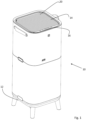
- the air-purifier 10 has a control panel 16.
- the control panel 16 is in the embodiment of Fig. 1 located at the front of the top of the air purifier 10.
- the control panel 16 acts as a user interface whereby a user can b control various functions of the air-purifier 10. Such functions can be ON/OFF, fan speed and also the louver arrangement 20.
- a fixed vane 26 can be located between the first louver 22 and the second louver 24.
- the fixed vane 26 can act to improve stability and make the louver arrangement 20 more robust.
- the individual vanes can be interconnected to a set of shafts 28.
- three shafts 28 interconnect the vanes of the first louver 22 and a set of three shafts 28 interconnects the vanes of the second louver 24.
- the shafts 28 can advantageously run in a direction perpendicular to the longitudinal direction of the vanes of the first louver 22 and the second louver 24.
Landscapes
- Engineering & Computer Science (AREA)
- Chemical & Material Sciences (AREA)
- Combustion & Propulsion (AREA)
- Mechanical Engineering (AREA)
- General Engineering & Computer Science (AREA)
- Air-Flow Control Members (AREA)
Abstract
An air-conditioner (10 is provided. The air conditioner comprises a fan (30) and an air outlet. The air conditioner further comprises a louver arrangement comprising a first louver (22) and a second louver (24). Each of the first and second louver comprises a set of parallel vanes that can be angled with respect to the air outlet. The louver arrangement further comprises a first drive arrangement connected to the first louver for driving the first louver, and a second drive arrangement connected to the second louver for driving the second louver. The air conditioner also comprises a control unit (40) configured to control the drive of the first and second drive arrangements, respectively, and the control unit is configured to drive each of the louvers independently in a swinging motion.
Description
- The invention relates to an air conditioner. In particular present invention relates to an air conditioner comprising a louver arrangement. The louver arrangement can be used to adjust the outlet air flow from the air-conditioner.
- Air conditioning is a collective expression for conditioning air into a desired state. Thus, an air-conditioner can be used to treat air. It could be heating the air during cold periods, cooling the air during warmer periods or for cleaning/purifying the air if it contains unwanted particles. It can also humidify or dehumidify air. In general, an air conditioner has an air inlet some air treatment component and an air outlet,
- Typically, the final output from the air-conditioner is conditioned air blown into a room or some other space. It is typically desired that the air is delivered at low noise, in a sufficient amount and also the process of delivering air should be energy efficient.
- To direct the air into the room a so-called louver can be used at the air output from the air-conditioner. Thus, a louver can be described as a movable element provided to displace air blown by a fan of the air-conditioner. One or more such movable elements or louvers can be provided at the air outlet. The louver(s) can deflect the air stream and aim it at a specific direction.
- For example,
JP3748049 - There is a constant desire to improve air conditioners. Hence, there exists a need for an improved air conditioner and also to a louver arrangement for an air-conditioner.
- It is an object of the present invention to provide an improved air-conditioner. In particular it is an object to improve the air distribution from an air-conditioner provided with a louver. It is a further object of the present invention to provide an improved louver arrangement for an air-conditioner.
- These objects and or others are obtained by an air conditioner having a louver arrangement as set out in the appended claims.
- In accordance with the invention an air conditioner, in particular an air purifier, is provided. The air conditioner comprises a fan and an air outlet. The air conditioner further comprises a louver arrangement comprising a first louver and a second louver. Each of the first and second louver comprises a set of parallel vanes that can be angled with respect to the air outlet. The louver arrangement further comprises a first drive arrangement connected to the first louver for driving the first louver, and a second drive arrangement connected to the second louver for driving the second louver. The air conditioner also comprises a control unit configured to control the drive of the first and second drive arrangements, respectively. and the control unit is configured to drive each of the louvers independently in a swinging motion. Hereby additional control options for the user can be obtained and also a mode of operation where space coverage for conditioned air can be increased. For example, for an air purifier it can be beneficial to provide purified air to an entire room so that purified air reaches the entire room.
- In accordance with one embodiment, the control unit is configured to drive each of the louvers in a synchronized swinging motion. Hereby a particularly useful mode of operation for improving space coverage can be obtained.
- In accordance with one embodiment, the control unit is configured to drive one of the louvers in a swinging motion and keep one of the louvers at a fixed angle. Hereby a comfortable mode of operation for the air conditioner can be provided.
- In accordance with one embodiment, a fixed vane is located between the first louver and the second louver. Hereby robustness of the louver arrangement can be improved.
- In accordance with one embodiment, the air outlet is a vertical air outlet located at the top of the air-conditioner. Hereby an efficient and comfortable air stream can be provided from the air outlet.
- In accordance with some embodiment, the vanes of the first louver and the vanes of the second louver are arranged in parallel with a front section of the air conditioner. Hereby the air from the air conditioner, can be directed in a user-friendly manner. For example, the vanes can be configured to have a mid-position where the vanes are in a vertical position and the air distribution can be easy to set to match how the user wants the air to be distributed into a room.
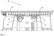
- In accordance with some embodiments, each of the first drive arrangement and the second drive arrangement comprises a stepper motor configure to drive the respective first and second louvers. Hereby an efficient and easy to control implementation of the drive arrangement can be provided. In particular the stepper motors can be connected to the louvers via a gearing and a teethed shaft.
- The invention will now be described in more detail, by way of example, and with reference to the accompanying drawings, in which:
-
Fig. 1 is a view of an air purifier with a louver arrangement, -
Fig. 2 is a top view of the air purifier inFig. 1 , -
Fig. 3 is a cross sectional view of the air purifier ofFig. 1 , and -
Fig. 4 is a view illustrating a detail of the cross-sectional view ofFig. 3 . - The invention will now be described more fully hereinafter with reference to the accompanying drawings, in which certain embodiments of the invention are shown. The invention may, however, be embodied in many different forms and should not be construed as limited to the embodiments set forth herein; rather, these embodiments are provided by way of example so that this disclosure will be thorough and complete, and will fully convey the scope of the invention to those skilled in the art. For example, like or similar components of different embodiments can be exchanged between different embodiments. For example, the louver arrangement as described herein is shown mounted on an air purifier, but the louver arrangement could equally be mounted on any type of air conditioner. Some components can be omitted from different embodiments. Also, some components typically used in an air-conditioner have been omitted to more clearly show the invention. Like numbers refer to like elements throughout the description.
- In
Fig. 1 , a front view in perspective of an air-conditioner 10 is depicted. The air-conditioner ofFig. 1 is an air-purifier 10. However, the air-conditioner can also be of other types. The air-purifier 10 has anair inlet 12 and anair outlet 14. The air inlet can be located at the bottom part of theair purifier 10, but can also be on the sides thereof or both. Further, in the exemplary embodiment ofFig. 1 , the air outlet is located at a top section of the air-purifier 10. However, it is also envisaged that the air outlet could be located at some other location such as at a side panel of the air-purifier 10. At the air outlet 14 alouver arrangement 20 is located. - Further, the air-
purifier 10 has acontrol panel 16. Thecontrol panel 16 is in the embodiment ofFig. 1 located at the front of the top of theair purifier 10. Thecontrol panel 16 acts as a user interface whereby a user can b control various functions of the air-purifier 10. Such functions can be ON/OFF, fan speed and also thelouver arrangement 20. - In
Fig. 2 , a top view of the air-purifier 10 ofFig. 1 is shown. As set out above, alouver arrangement 20 is provided at the air outlet. Thelouver arrangement 20 is divided into two groups such that the louver arrangement comprises afirst louver 22 and asecond louver 24. Each of thefirst louver 22 and thesecond louver 24 comprises a set of parallel vanes that can be angled with respect to the air outlet. The vanes can have an elongated shape extending from one end of the air outlet to the opposite end of the air outlet. Thus, by angling the vanes of thelouvers - Further, in accordance with the exemplary embodiment of
Fig. 2 , a fixedvane 26 can be located between thefirst louver 22 and thesecond louver 24. The fixedvane 26 can act to improve stability and make thelouver arrangement 20 more robust. In order to keep the vanes of thefirst louver 22 and also thesecond louver 24 parallel, the individual vanes can be interconnected to a set ofshafts 28. In the embodiment ofFig. 2 , threeshafts 28 interconnect the vanes of thefirst louver 22 and a set of threeshafts 28 interconnects the vanes of thesecond louver 24. Theshafts 28 can advantageously run in a direction perpendicular to the longitudinal direction of the vanes of thefirst louver 22 and thesecond louver 24. - In
Fig. 3 , a cross sectional view from the side of theair purifier 10 inFigs. 1 and2 is shown. Theair purifier 10 has afan 30 for blowing conditioned air from the air purifier into a room or some other space via the air outlet. Theair purifier 10 further comprises afirst drive arrangement first louver 22 for driving thefirst louver 22. In this exemplary embodiment, thefirst drive arrangement stepper motor 23 operatively connected to a teetheddrive shaft 27. The teeth of the teetheddrive shaft 27 are disposed between the vanes of thefirst louver 22 so that when the stepper motor is run the vanes are tilted so as to be angled with respect to the air flow out from the air outlet. In a similar manner asecond drive arrangement second louver 24. - Further, a
control unit 40 arranged in the air purifier. Thecontrol unit 40 is configured to control the drive of thefirst drive arrangement second drive arrangement control unit 40 is formed on an electric circuit board (ECB) located inside theair purifier 10. Further, thecontrol unit 40 can be configured to control thefirst louver 22 and the second louver independently. This is made possible thanks to the provision of a plurality of drive arrangements and by letting the drive arrangements be controlled by thecontrol unit 40. In particular, thecontrol unit 40 can be configured to drive each of the first andsecond louvers - Thus, by configuring the controller to drive the, at least, two
louvers louvers second louvers second louvers second louvers second louvers back side 24 is tilted (angled) more than the other, front,louver 22. - In another embodiment, the control unit is configured to drive one of the louvers in a swinging motion and keep one of the louvers at a fixed angle.
- In
Fig. 4 , the mechanism for driving the louvers is shown in more detail. InFig. 4 the covers of thestepper motors Fig. 4 , thestepper motors drive shafts gearing 21. The drive arrangements thus formed having a stepper motor driving a teethed shaft via a gearing can allow for an accurate and smooth drive of thelouvers - The drive of the louvers as described herein can provide a comfortable air distribution for an air-conditioner and in particular an air purifier. Thus, heating and humidity can be distributed in a comfortable manner using the swinging louvers. Also, whereas the embodiments described only comprises two individually controlled louvers, the control can be extended to more than two louvers such as three or even more.
Claims (10)
- An air conditioner comprising:- a fan,- an air outlet, anda louver arrangement (20) comprising:- a first louver (22),- a second louver (24),- each of the first and second louver comprising a set of parallel vanes that can be angled with respect to the air outlet.- a first drive arrangement connected to the first louver for driving the first louver,- second drive arrangement connected to the second louver for driving the second louver,
and- a control unit configured to control the drive of the first and second drive arrangements, respectively, wherein the control unit is configured to drive each of the louvers independently in a swinging motion. - The air conditioner according to claim 1, wherein the control unit is configured to drive each of the louvers (22, 24) in a synchronized swinging motion.
- The air conditioner according to claim 1, wherein the control unit is configured to drive one of the louvers (22, 24) in a swinging motion and keep one of the louvers (22, 24) at a fixed angle.
- The air conditioner according to any one of claims 1-3, wherein a fixed vane (26) is located between the first louver and the second louver.
- The air conditioner according to any one of claims 1 - 4, wherein the air outlet is a vertical air outlet located at the top of the air-conditioner.
- The air conditioner according to claim 5, wherein the vanes of the first louver and the vanes of the second louver are arranged in parallel with a front section of the air conditioner.
- The air conditioner according to claim 5 or 6, wherein the vanes are configured to have a mid-position where the vanes are in a vertical position.
- The air conditioner according to any one of claims 1 - 7, wherein each of the first drive arrangement and the second drive arrangement comprises a stepper motor (27, 29) configure to drive the respective first and second louvers (22,24).
- The air conditioner according to claim 8, wherein the stepper motors (27, 29) are connected to the louvers (22, 24) via a gearing (21) and a teethed shaft (23, 25).
- The air conditioner according to any one of claims 1 - 9, wherein the air-conditioner is an air purifier (10).
Applications Claiming Priority (1)
| Application Number | Priority Date | Filing Date | Title |
|---|---|---|---|
| SE2330372 | 2023-08-29 |
Publications (1)
| Publication Number | Publication Date |
|---|---|
| EP4517197A1 true EP4517197A1 (en) | 2025-03-05 |
Family
ID=94478341
Family Applications (1)
| Application Number | Title | Priority Date | Filing Date |
|---|---|---|---|
| EP24184854.8A Pending EP4517197A1 (en) | 2023-08-29 | 2024-06-27 | Air conditioner with controlled louver arrangement |
Country Status (1)
| Country | Link |
|---|---|
| EP (1) | EP4517197A1 (en) |
Cited By (1)
| Publication number | Priority date | Publication date | Assignee | Title |
|---|---|---|---|---|
| CN121498193A (en) * | 2026-01-13 | 2026-02-10 | 珠海格力电器股份有限公司 | air purifier |
Citations (6)
| Publication number | Priority date | Publication date | Assignee | Title |
|---|---|---|---|---|
| JPH11211189A (en) * | 1998-01-22 | 1999-08-06 | Mitsubishi Heavy Ind Ltd | Air conditioner |
| JP3748049B2 (en) | 2001-04-13 | 2006-02-22 | シャープ株式会社 | Air conditioner outlet opening and closing device |
| KR20170081820A (en) * | 2016-01-05 | 2017-07-13 | 주식회사 대유위니아 | Apparatus for adjusting wind direction of air conditioner |
| CN111023285A (en) * | 2019-12-05 | 2020-04-17 | 宁波奥克斯电气股份有限公司 | A kind of air conditioner with bidirectional wind guide function and control method thereof |
| US10739033B2 (en) * | 2015-08-06 | 2020-08-11 | Mitsubishi Electric Corporation | Air-conditioning apparatus |
| CN112377988A (en) * | 2020-11-17 | 2021-02-19 | 珠海格力电器股份有限公司 | Air outlet structure and cabinet air conditioner |
-
2024
- 2024-06-27 EP EP24184854.8A patent/EP4517197A1/en active Pending
Patent Citations (6)
| Publication number | Priority date | Publication date | Assignee | Title |
|---|---|---|---|---|
| JPH11211189A (en) * | 1998-01-22 | 1999-08-06 | Mitsubishi Heavy Ind Ltd | Air conditioner |
| JP3748049B2 (en) | 2001-04-13 | 2006-02-22 | シャープ株式会社 | Air conditioner outlet opening and closing device |
| US10739033B2 (en) * | 2015-08-06 | 2020-08-11 | Mitsubishi Electric Corporation | Air-conditioning apparatus |
| KR20170081820A (en) * | 2016-01-05 | 2017-07-13 | 주식회사 대유위니아 | Apparatus for adjusting wind direction of air conditioner |
| CN111023285A (en) * | 2019-12-05 | 2020-04-17 | 宁波奥克斯电气股份有限公司 | A kind of air conditioner with bidirectional wind guide function and control method thereof |
| CN112377988A (en) * | 2020-11-17 | 2021-02-19 | 珠海格力电器股份有限公司 | Air outlet structure and cabinet air conditioner |
Cited By (1)
| Publication number | Priority date | Publication date | Assignee | Title |
|---|---|---|---|---|
| CN121498193A (en) * | 2026-01-13 | 2026-02-10 | 珠海格力电器股份有限公司 | air purifier |
Similar Documents
| Publication | Publication Date | Title |
|---|---|---|
| EP3015776B1 (en) | Air conditioner | |
| EP1041351A1 (en) | Indoor unit for air conditioner | |
| CN103712282A (en) | Indoor unit of air conditioner and method of controlling the same | |
| EP3450764A1 (en) | Tangential fan and air conditioner | |
| EP1707893B1 (en) | Air conditioner | |
| KR20150004991A (en) | Wind adjusting apparatus | |
| CN109084370A (en) | Air conditioner indoor unit and air conditioner | |
| JP2000111131A (en) | Air outlet structure of blower | |
| JPH0599480A (en) | Blow-off control device for air conditioner | |
| JP4752142B2 (en) | Indoor unit for air conditioner | |
| US6210269B1 (en) | Oscillating drive for air flow discharge | |
| KR102336631B1 (en) | Air-conditioner | |
| WO2020169204A1 (en) | Air-conditioner with displacabe louver | |
| WO1999008051A1 (en) | Method and apparatus for controlling air flow in indoor machine of air conditioner | |
| US20230296285A1 (en) | Dual louver arrangement | |
| CN105157104B (en) | Air conditioner cabinet | |
| CN219014570U (en) | Air quantity adjusting device of heating ventilation air conditioner and heating ventilation air conditioner | |
| CN114391080A (en) | Indoor unit of air conditioner | |
| KR100470483B1 (en) | Five Direction Deflation Type Air-Conditioner | |
| JP2013170763A (en) | Indoor unit of air conditioner | |
| JPH06323620A (en) | Blower control device for air conditioner | |
| KR20010028973A (en) | Wind direction controller for air conditioner | |
| KR0136044Y1 (en) | Wing of airconditioner | |
| KR100339595B1 (en) | Apparatus and method for controlling wind direction of air conditioner | |
| US20220373223A1 (en) | Air-processing apparatus |
Legal Events
| Date | Code | Title | Description |
|---|---|---|---|
| PUAI | Public reference made under article 153(3) epc to a published international application that has entered the european phase |
Free format text: ORIGINAL CODE: 0009012 |
|
| STAA | Information on the status of an ep patent application or granted ep patent |
Free format text: STATUS: THE APPLICATION HAS BEEN PUBLISHED |
|
| AK | Designated contracting states |
Kind code of ref document: A1 Designated state(s): AL AT BE BG CH CY CZ DE DK EE ES FI FR GB GR HR HU IE IS IT LI LT LU LV MC ME MK MT NL NO PL PT RO RS SE SI SK SM TR |
|
| STAA | Information on the status of an ep patent application or granted ep patent |
Free format text: STATUS: REQUEST FOR EXAMINATION WAS MADE |
|
| 17P | Request for examination filed |
Effective date: 20250905 |