-
The present invention relates to a household appliance with an outer surface interrupted by a separation gap and a lighting device for impacting the visibility of the separation gap and remotely communicating visual signals.
-
In general terms, the household appliances referred to in the invention comprise:
- a housing delimiting a treatment seat adapted to accommodate and/or support one or more household products (clothes, dishes, food products, furnishing surfaces, fabrics) in a treatment position to subject them to a desired treatment.
- one or more treatment devices arranged inside the housing and operable to carry out one or more specific treatments at the treatment position.
- one or more treatment detection devices arranged inside the housing and configured to detect one or more treatment parameter values of the treatment to which the household product is subjected in the treatment position,
- optionally, one or more anomaly detectors arranged inside the housing and configured to detect one or more operating anomalies of the household appliance,
- an electronic control system arranged in the housing and in signal connection with the treatment device and treatment detector and configured to control the operation of the treatment device depending on a treatment program and depending on the values detected by the treatment detector.
- a user interface in signal connection with the electronic control system to allow the user to select (parameters of) a treatment program of the household product and display parameters of the selected and/or running treatment program,
where the housing has an outer surface interrupted by a separation gap.
-
Due to the technical function thereof, the separation gaps have non negligible extensions, are difficult to conceal from the user's sight, and form household appliance zones which are esthetically unsatisfactory and currently unused.
-
When the separation gaps delimit suction or ventilation mouths of the household appliance, the latter are frequently and undesirably visible to the user and perceived as anti-esthetic or poorly clean.
-
Therefore, it is the object of the present invention to suggest a household appliance with an outer surface interrupted by a separation gap, having features such as to obviate at least some of the drawbacks of the prior art.
-
It is a particular object of the invention to suggest a household appliance with an outer surface interrupted by a separation gap, having features such as to utilize the zone of the separation gap to communicate visual signals remotely, for example at a greater distance than the legibility with the naked eye of a traditional user interface.
-
It is a further (independent, but synergic) particular object of the invention to provide a household appliance with an outer surface interrupted by a separation gap, having features such as to positively impact the esthetics of the household appliance at the separation gap.
-
These and other objects are achieved by a household appliance according to claim 1. The dependent claims relate to advantageous and preferred embodiments.
-
According to an aspect of the invention:
- the separation gap forms an elongated interstice space, delimited by a first intrados (intended as a lateral elongated delimitation face), a second intrados (intended as a lateral elongated delimitation face) opposite to and facing the first intrados, and a gap bottom, and an open passage towards the exterior of the household appliance,
- the household appliance comprises a lighting device positioned behind the outer surface and configured to project a light strip onto the first intrados, resulting in a light path which, starting from the lighting device, crosses the interstice space transversely to a longitudinal extension thereof and impacts the first intrados and is reflected by the first intrados so as to continue through the open passage outside the household appliance.
-
The lighting device allows utilizing the zone of the separation gap for remotely communicating visual signals, e.g., at a greater distance than the legibility with the naked eye of a traditional user interface.
-
The lighting device also allows positively impacting the esthetics of the household appliance at the separation gap.
-
According to an aspect of the invention, the separation gap is positioned in a front face of the household appliance (vertically oriented in the position of installation and use of the household appliance) with the longitudinal extension oriented horizontally, where the longitudinal extension can be rectilinear (in the case of a flat front face of the household appliance) or curved (in the case of a convex front face of the household appliance), where the light strip projected onto the first intrados also extends horizontally.
-
The horizontal orientation of the projected light strip creates a visual signaling effect easily and naturally perceivable by humans, without generating associations of stress or danger. Furthermore, the horizontal light strip divides, but simultaneously visually connects the bordering regions of the outer surface of the household appliance, neutralizing the visual effect of the geometric shape of the gap.
-
According to an aspect of the invention, at least one of the first intrados, the second intrados and the gap bottom delimits at least one outlet opening of a ventilation channel, where the lighting device and the separation gap are configured so that the outlet opening is in a shaded zone, not lit by the light strip projected onto the first intrados.
-
Particularly advantageously, the light strip projected onto the first intrados divides the interstice space into:
- an inner space facing the interior of the household appliance and defining a (or the aforesaid) shaded zone,
- an outer space facing the exterior of the household appliance and defining a zone lit by the lighting device.
-
This allows using the separation gap zone for remotely communicating visual signals, while obviating an undesired lighting of structures which are esthetically inadequate, but technically indispensable or functionally desired within the separation gap.
-
A synergy is thus obtained between the two main technical effects of the invention.
-
Further advantageous aspects of the invention will become apparent from the following description of some embodiments thereof, given by way of non-limiting example, with reference to the accompanying drawings, in which:
- Figure 1 is a front view of a household appliance, or cooking oven, where a horizontal dotted-dashed line indicates the position or plane of a separation gap of an outer surface of the household appliance or cooking oven, and the position or plane of a projected light strip, according to an embodiment.
- Figure 2 is a section view of the household appliance or cooking oven in figure 1.
- Figure 2A is an enlarged view of a detail in figure 2.
- Figure 3 is an exploded perspective view showing an outer covering part of the household appliance, e.g., a control panel, e.g., of a cooking oven, detached from a support structure of the household appliance, according to an embodiment.
- Figures 3A and 3B are enlarged views of a detail in figure 3 in a detached configuration and in an assembled configuration.
- Figure 4 is an exploded perspective view showing an outer covering part of the household appliance, e.g., a control panel, e.g., of a cooking oven, and a lighting device detached from the outer covering part or from the control panel, according to an embodiment.
- Figure 4A is a perspective view, where the lighting device is coupled to the outer covering part or to the control panel.
- Figure 4B is an enlarged view of a detail in figure 4A.
- Figure 5 is a side view of the lighting device, according to an embodiment.
- Figures 5A and 5B are perspective views of the lighting device in figure 5.
- Figure 5C is an exploded perspective view of the lighting device according to an embodiment, in which a first half-shell and a second half-shell for housing the lighting device, a lighting strip, e.g., a LED strip, and a transparent or translucent plate or layer can be seen.
- Figures 5D and 5E are views in two different section planes, transverse to a longitudinal extension of the lighting device, according to an embodiment.
- Figures 6A - 6G show an assembly sequence of the lighting device according to an embodiment.
- Figure 7 is a section view of a first half-shell (or a first housing part) of the lighting device, where a dashed line indicates the polished reflection surface extension, and a continuous zig-zag line indicates a stepped or notched region of planned reflection disturbance.
- Figure 8 is a section view of a second half-shell (or a second housing part) of the lighting device, where a dashed line indicates the extension of polished reflection surfaces.
- Figure 9 is a section view of a part of the household appliance or the cooking oven, showing the separation gap and the lighting device, as well as a light path and a lit region (gray shading) generated by the lighting device, according to an embodiment.
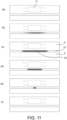
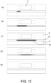
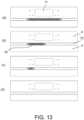
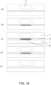
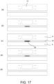
- Figures 10 to 18 show light signaling modes and sequences implementable by means of the lighting device, according to embodiments.
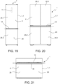
- Figures 19, 20, 21 are front views of household appliances with a lighting device, where a horizontal dotted-dashed line indicates the position or plane of a separation gap of an outer surface of the household appliance, and the position or plane of a projected light strip, according to embodiments, where the depicted household appliances are one or more of a cooking oven, a refrigerator, a microwave oven, a dishwasher, a washing machine, a tumble dryer.
- Figure 22 is a diagrammatic view of a cooking oven according to an embodiment.
- Figure 23 is a diagrammatic view of a washing machine according to an embodiment.
- Figure 24 is a diagrammatic view of a laundry dryer according to an embodiment.
- Figure 25 is a diagrammatic view of a washer-dryer according to an embodiment.
- Figure 26 is a diagrammatic view of a dishwasher according to an embodiment.
- Figure 27 is a diagrammatic view of a microwave oven according to an embodiment.
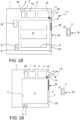
- Figure 28 is a diagrammatic view of a refrigerator according to an embodiment.
- Figure 29 is a diagrammatic view of a freezer according to an embodiment.
-
With reference to the drawings, a household appliance 1 comprises:
- a housing 2 with an outer wall 3 and an outer surface 4 interrupted by a separation gap 12,
- a treatment seat 5 adapted to accommodate and/or support one or more household products (clothes, dishes, food products, furnishing surfaces, fabrics) in a treatment position 6,
- at least one treatment device 7 arranged inside the housing 2 and operable to carry out a treatment at the treating position 6 and subject the household product to said treatment,
- at least one treatment detector 8 at least partially arranged inside the housing 2 and configured to detect a treatment parameter value of the treatment carried out by the treatment device 7.
- optionally, at least one anomaly detector 9 at least partially arranged inside the housing 2 and configured to detect a quantity indicating an operating anomaly of the household appliance 1,
- an electronic control system 10 arranged in the housing 2 and in signal connection with the treatment device 7 and the treatment detector 8 and configured to control the treatment device 7 depending on a treatment program and depending on the value detected by the treatment detector 8,
- a user interface 11 in signal connection with the electronic control system 10 to allow the user to select (parameters of) a treatment program of the household product and display parameters of the selected and/or running treatment program.
-
The separation gap 12 forms an elongated interstice space (or groove or recess) 13, delimited by a first intrados 14 (intended as a lateral elongated delimitation face), a second intrados 15 (intended as a lateral elongated delimitation face) opposite to and facing the first intrados 14, and a gap bottom 16, and an open passage 17 towards the exterior of the household appliance 1.
-
The household appliance 1 comprises a lighting device 18 positioned behind the outer surface 4 (thus further inside the household appliance than the outer surface 4) and configured to project a light strip 19 onto the first intrados 14, resulting in a light path 20 which, starting from the lighting device 18, crosses the interstice space 13 transversely to a longitudinal extension thereof and impacts the first intrados 14 reflecting the light so as to continue through the open passage 17 outside the household appliance 1 ( figure 9 ).
-
The lighting device 18 allows utilizing the zone of the separation gap 12 for remotely communicating visual signals, e.g., at a greater distance than the legibility with the naked eye of a traditional user interface.
-
The lighting device 18 further allows positively impacting the esthetics of the household appliance 1 at the separation gap 12.
-
According to an embodiment ( figures 1 , 19 - 21 ), the separation gap 12 is positioned in a front face 20 of the household appliance 1 (vertically oriented in the position of installation and use of the household appliance 1) with the longitudinal extension of the separation gap 12 oriented horizontally or lying in a horizontal plane, wherein the longitudinal extension of the separation gap 12 can be rectilinear (in the case of a flat front face 20) or curved (in the case of a convex front face 20), wherein the first intrados 14 and/or the light strip 19 projected onto the first intrados 14 also extends horizontally. The first intrados 14 and/or the light strip 19 projected onto the first intrados 14 can be planar or curved, for example, but with a horizontal extension in at least one linear direction, e.g., according to a horizontal plane or a plane inclined downwards in a forward direction of the household appliance 1 (as can be seen in figure 2A , for example).
-
The horizontal orientation of the projected light strip 19 creates a visual signaling effect easily and naturally perceivable by humans, without generating associations of stress or danger. Furthermore, the horizontal light strip 19 divides, but simultaneously visually joins the bordering regions of the outer surface 4 of the household appliance 1, neutralizing the visual effect of the geometric shape of the separation gap 12.
-
According to an embodiment ( figures 2A , 9 ), at least one of the first intrados 14, the second intrados 15, and the gap bottom 16 delimits at least one outlet opening 21 of a ventilation channel 22 (air ejection and/or suction channel), where the lighting device 18 and the separation gap 12 are configured so that the outlet opening 21 is in a shaded zone 23 not lit by the lighting device 18, in particular not lit by the light strip 19 projected onto the first intrados 14.
-
Particularly advantageously, the light strip 19 projected onto the first intrados 14 divides the interstice space 13 into:
- an inner space 13i facing the interior of the household appliance 1 and defining a (or the aforesaid) shaded zone 23,
- an outer space 13e facing the exterior of the household appliance 1 and defining a zone lit by the lighting device 18 ( figure 9 ).
-
This allows using the separation gap 12 for remotely communicating visual signals, while obviating an undesired lighting of structures which are esthetically unsatisfactory but technically indispensable or functionally desired within the separation gap 12.
-
A synergy is thus obtained between the two main technical effects of the invention.
-
According to embodiments ( figures 10 - 18 ), the lighting device 18 is operable or configured to vary features (e.g., the position, the length, the color, the light intensity) of the light strip 19 over time, depending on an operating state and/or operating parameters of the household appliance 1. To this end, the lighting device is in signal connection with and controlled by the electronic control system 10. This provides light feedback, positioned on the household appliance 1, for communicating to the user, at a distance of up to at least 5 meters, an operating state of the household appliance 1, e.g., on and off state, an operating state, a charging state with the household product.
-
According to an embodiment, the lighting device is configured to vary the color of the light strip 19 between at least two different colors, e.g., between four different colors, e.g., between blue, white, red and yellow.
-
Advantageously, each different color of the light strip 19 is a different, specific piece of information on the state of operation of the household appliance 1. The colors and/or change in color of the light strip 19 can be set or adjusted or deactivated by the user by means of the user interface 11 on board the household appliance 1 or made in a remote electronic device 24, e.g., a smart phone or tablet computer.
-
According to an embodiment, automatic signals of anomaly/operation error of the household appliance 1 by means of the light strip 19 cannot be deactivated by the user.
-
For example, the household appliance 1 is one of:
- a household cooking oven 1.1 ( figures 1, 2, 2A , 26 ),
- a washing machine 1.2 ( figure 22 ),
- a tumble dryer 1.3 ( figure 23 ),
- a washer-dryer 1.4 ( figure 24 ),
- a dishwasher 1.5 ( figure 25 ),
- a microwave oven 1.6 ( figure 27 ),
- a refrigerator 1.7 ( figure 28 ),
- a freezer 1.8 ( figure 29 ),
-
According to embodiments, the household products which are treated by means of the household appliance 1 can comprise one or more of:
- food products to be heated and/or cooked and/or defrosted and/or frozen and/or cooled,
- clothes to be washed and/or dried,
- dishes to be washed.
Description of embodiments of the separation gap 12 and corresponding positions of the light strip 19
-
The separation gap 12 can be formed, for example, between two outer surface portions 4 movable with respect to each other, e.g., a gap between an edge of a door 25 and a fixed adjacent edge of the household appliance 1.
-
The separation gap 12 can be formed, for example, and the light strip 19 can thus be generated, between the door 25 and a control panel 26 of the household appliance 1 and clearly visible when the door 25 is closed ( figures 1, 2A , 9 ), e.g., in an oven 1.1 or a dishwasher 1.5. Advantageously, the first intrados 14 can be formed by an upper edge of the door 25 and/or a handle 46 of the door 25, e.g., in the cooking oven 1.1.
-
The separation gap 12 can be formed, for example, between an edge of a first door or drawer 25.1 and an adjacent edge of a second door or drawer 25.2 of a refrigerator 1.7 or freezer 1.8 or combined refrigerator-freezer ( figures 19, 20, 21 ).
-
The separation gap 12 can be formed, for example, between an edge of a hatch and a fixed adjacent edge of a washing machine 1.2 or a tumble dryer 1.3.
-
The separation gap 12 can be formed, for example, between an edge of a drawer and a fixed adjacent edge, e.g., of a control panel, of a drawer-type dishwasher.
-
The separation gap 12 can be formed, for example, between an edge of a first drawer and an adjacent edge of a second drawer of a drawer-type dishwasher.
-
The separation gap 12 can be formed, for example, at structural or functional slits of the household appliance 1, e.g., at an air ejection or suction slit in an oven 1.1 or a dishwasher 1.5 or a tumble dryer 1.3 or a refrigerator 1.7.
-
All the positions indicated for the separation gap 12 are particularly advantageous for a corresponding arrangement and configuration of the lighting device for generating the light strip 19 in said positions.
Description of embodiments of the lighting device 18
-
According to an embodiment, the lighting device 18 is arranged inside the household appliance 1 or at least covered by the outer wall 3 or the outer surface 4 and is not directly visible and/or accessible to users from outside the household appliance 1. This allows optimizing the lighting device 18 without having to consider the esthetic appearance thereof.
-
According to an embodiment ( figures 2A , 3 , 4C ), the lighting device 18 is arranged on a rear side of a control panel 26 of the household appliance 1, e.g., of the oven 1.1, in which control panel 26 the user interface 11 and at least part of the electronic control system 10 are integrated. The lighting device 18 can be directly connected, mechanically and electrically, to the control panel 26, i.e., mechanically connected to the control panel 26 and electrically connected to the electronic control system 10.
-
The lighting device 18 comprises a lighting strip 27 with a PCB circuit board 28 and a plurality of LEDs 29 arranged in a row, e.g., RGBW LEDs, selectively controllable by the PCB circuit board 28, and its own light guide housing 30, for example distinct from the control panel 26, which supports and positions the lighting strip 27 and which forms a light guide channel 31 for guiding the light from the lighting strip 27 to a light outlet slit 32 of the light guide housing 30 ( figures 5 , 5A- 5E ).
-
The lighting device 18 can further comprise a refraction plate or layer 33 positioned in the light path, e.g., in the light guide housing 30 to cause a refraction of the light from the lighting strip 27 before said light is reflected by the first intrados 14. This allows evening the light intensity and diffusing the light along the light strip 19, despite the original generation of the light in discrete points by means of the LEDs. The refraction plate or layer 33 can be transparent or translucent ( figures 5C , 5D,5E ).
-
According to an embodiment, the light guide housing 30, which is preferably made of plastic, is self-supporting and structurally distinct from the control panel 26 of the household appliance 1. This allows for a modular design and a high degree of prefabrication of the single components of the household appliance 1.
-
According to an embodiment, the light guide housing 30 forms coupling portions 34, for example snap-on teeth ( figures 4, 4B , 6F ) for a snap engagement (without requiring screws or gluing) with corresponding counter-coupling portions 35, for example stop edges ( figures 4, 4B ) of the household appliance 1, in particular of the control panel 26 or a board of the electronic control system 10. This facilitates and accelerates assembly.
-
According to an embodiment, the light guide housing 30 comprises a first half-shell 36 (half-shell higher up in figure 5C and lower down in figure 5D) and a second half-shell 37 (half-shell lower down in figure 5C and higher up in figure 5D) mutually connectable by snap engagement ( figures 6E, 6F, 6G ), e.g., by means of a combined engagement movement of translational insertion and subsequent snap-engagement rotation.
-
To this end, the first half-shell 36 and the second half-shell 37 form:
- the one (36 or 37) at least one or more hooks 38 and the other (37 or 36) at least one or more corresponding counter-coupling holes 39 for an initial insertion and coupling therebetween, and
- the one (37 or 36) at least one or more stop hooks 40 and the other (36 or 37) at least one or more corresponding stop holes 41 for stopping the first and second half- shells 36, 37 in the assembled position ( figures 6E, 6F, 6G ).
-
This allows making the light guide housing 30 in single components by injection molding and then quickly and precisely assembling them.
-
The light guide housing 30, in particular the first half-shell 36 and/or the second half-shell 37 form one or more LED seats 42, e.g., a groove or snap-on teeth, for accommodation by (simple) insertion (e.g., snap-on insertion) of the lighting strip 27 ( figures 6C, 6D ).
-
The light guide housing 30, in particular the second half-shell 37 and/or the first half-shell 36 form one or more refraction seats 43, e.g., a groove, for accommodation by (simple) insertion of the refraction plate or layer 33 ( figures 6A, 6B ).
-
This allows a precise and planned positioning of the optical components with reference to the light guide channel 31.
-
According to an embodiment, the light guide channel 31 forms, between the lighting strip 31 and the refraction plate or layer 33, a first polished surface 44 and a second polished surface 45 opposed to each other and reflecting the light from the lighting strip 31 so as to guide it through the light outlet slit 32 towards the first intrados 14 ( figures 7, 8 ).
-
The first polished surface 44 and the second polished surface 45 are preferably formed, the one in the first half-shell 36 and the other in the second half-shell 37, and/or possibly polished or mirror-polished or coated with a polished layer after formation by injection molding of the first half-shell 36 and the second half-shell 37. The polishing itself and control of the degree of shine are facilitated by the structure with two half-shells of the light guide housing 30.
-
According to an embodiment ( figures 7, 9 ), the light guide channel 31 further forms at least one stepped or notched or roughened surface 45D preferably oblique to the first polished surface 44 and the second polished surface 45, and preferably downstream of the refraction plate/layer 33, to prevent the light from spreading towards the shaded zone 23.
-
According to an embodiment, reflecting surfaces of the light guide channel 31, which are not visible from outside the household appliance 1, are white, while reflecting surfaces of the light guide channel 31, which are visible from outside the household appliance 1, are of a color other than white, e.g., of the same color as the outer surface 4. This combines the need for good light reflection and esthetic continuity of the separation gap 12 with the outer surface 4.
-
According to a further embodiment, the lighting device 18 is in heat exchange communication with a ventilation channel 22 of the household appliance to avoid it from being overheated.
-
According to an embodiment, the/a control panel 26 of the household appliance 1 integrates the/a user interface 11 with display and forms a (preferably lower) delimitation wall 47 which forms a (preferably upper) side of the separation gap 12, e.g., the second intrados 15, and which forms:
- a central cavity 48 at which the lighting device 18 is positioned and which allows the light 19 generated by the lighting device 18 to pass,
- two shielding wall segments 49 at the two sides of the central cavity 48 seen in the direction of longitudinal extension of the delimitation wall 47, so as to prevent a lateral diffusion of the light generated, and possibly for delimitating and supporting further functions of the household appliance 1, e.g., water loading opening for a steam generation function in a cooking oven 1.1.
-
The control panel 26 has an injection-molded support structure made of plastic.
Description of signaling modes and sequences of the lighting device 18
-
According to an embodiment, with reference to a cooking oven 1.1., the electronic control system 10 and the lighting device 18 are configured so that:
- upon switching on the oven 1.1, the light strip 19 lights up the first intrados 14 (e.g., with a blue color), extending symmetrically, starting from a central point and a minimum extension of the light strip 19 in two opposite directions until reaching a maximum extension, at which it remains on for a predefined time, e.g., 2 seconds, before switching off (figure 10), dimming over the whole maximum extension, and/or
- upon switching off the oven 1.1, the light strip 19 lights up the first intrados 14 (e.g., with a blue color), starting with a gradual light intensification over the whole maximum extension of the light strip 19 and then symmetrically shortening from the maximum length towards a central point and a minimum extension of the light strip 19 until reaching the minimum extension and then switching off ( figure 11 ). It is an inverse sequence with respect to the lighting sequence in response to the switching on of the oven 1.1. And/or
- during a step of pre-heating the oven 1.1, the light strip 19 lights up the first intrados 14 (e.g., with a yellow or orange color), increasing from left to right (in a front view of the oven) like a "progress bar", where the progression of the extension of the light strip 19 depends on a temperature detected in the cooking cavity 50 of the oven 1.1. ( figure 12 ). Upon reaching a target temperature selected by means of the user interface 11, the light strip 19 has its maximum length and possibly dims and intensifies alternately to signal a state of "cooking in progress". And/or
- during a step of cooking completed of the oven 1.1, the light strip 19 lights up the first intrados 14 (e.g., with a white color), decreasing from its maximum length from right to left (in a front view of the oven) like a "progress bar", where the reduction in the extension of the light strip 19 depends on a difference between the cooking time elapsed and a target cooking time set by the user by means of the user interface 11 ( figure 13 ). Upon reaching the target cooking time selected by means of the user interface 11, the light strip 19 has a minimum length and possibly dims and intensifies alternately to signal a state of "cooking completed". And/or
- during a cooking step of oven 1.1 without selection of a target cooking time, the light strip 19 lights up the first intrados 14 (e.g., with a white color), symmetrically increasing and decreasing between a greater length and a smaller length and/or increasing and decreasing in light intensity in a pulsating mode ( figure 14 ) and/or
- during a cooking step of oven 1.1 with a temperature detector for the food in the cooking cavity 50 of the oven 1.1, the light strip 19 lights up the first intrados 14 (e.g., with a white color), increasing from left to right (in a front view of the oven) like a "progress bar", where the progression of the extension of the light strip 19 depends on a food temperature detected by means of the food temperature detector ( figure 12 ). Upon reaching a food target temperature selected by means of the user interface 11, the light strip 19 has its the maximum length and possibly dims and intensifies alternately to signal a state of "cooking completed".
-
The light signaling of the "cooking completed" state can comprise an in-length centered pulsation of the light strip 19, e.g., with a white color ( figure 15 ).
-
A light signaling of the "hot cooking cavity 50" can comprise a light intensity pulsation of the light strip 19, e.g., with a yellow or orange color, where the length of the light strip depends on the temperature of the cooking cavity 50 (figures 16, 17).
Detailed description of embodiments of the treatment devices 7
-
According to embodiments, the treatment devices 7 of the household appliance 1 can comprise one or more of:
- a hydraulic system 51 for filling and emptying and/or circulating water to wet the household products in the treatment position,
- a ventilation and/or air circulation system 52 for aerating the household products in the treatment position,
- a heating system 53 for heating the household products and/or heating the water of the hydraulic system and/or heating the air of the ventilation system,
- a dehumidification system 54 for drying the household products and/or dehumidifying (e.g., through condensation) the air of the ventilation system 52,
- a dispensing system 55 for dispensing one or more chemical substances for direct treatment on the household product and/or in the water of the hydraulic system 51 and/or in the air of the ventilation system 52,
- a mechanical agitation or movement system 56 for moving the household product and/or the treatment seat 5, for example for the purpose of dehydration by means of centrifugal action or variation in exposure of the household product to the treatment device 7 or agitation and remixing the household product,
- a microwave generator 57 for generating microwaves in the treatment position 6,
- a steam generator 58 for generating steam in the treatment position 6,
- a cooling and/or freezing system 59 adapted to cool and/or freeze the household products in the treatment position 6.
Detailed description of embodiments of the treatment detectors 8
-
According to embodiments, the treatment detectors 8 can comprise one or more of:
- a water pressure sensor 60,
- a water level sensor 61,
- a water temperature sensor 62,
- an air temperature sensor 62a,
- a water turbidity sensor 63,
- a treatment seat temperature sensor 64,
- food temperature sensor 65,
- an electrical quantity sensor 66 of an electric motor of the mechanical agitation and/or movement system 56,
- a presence sensor 67 of household products in the treatment position 6,
- a level or presence sensor 68 of a chemical treatment substance in the treatment substance dispensing system,
- a video camera 69 connected to or in the housing 2 and directed towards the treatment position 6 to monitor the household product during the treatment.
Detailed description of embodiments of the anomaly detectors 9
-
According to embodiments, the anomaly detectors 9 also are in signal connection with the electronic control system 10 and can comprise one or more of a temperature sensor, a water presence sensor, a smoke presence sensor, a water absence sensor, a position/presence sensor of movable or detachable parts of the household appliance.
-
According to embodiments, the electronic control system 10 controls the one or more treatment devices 7 and/or also controls the lighting device 18 depending on anomaly signals generated by the anomaly detectors 9.
Description of embodiments of the household appliance 1
-
The household cooking oven 1.1 ( figures 1, 2, 2A , 26 ) comprises a cooking cavity 50 forming the treatment seat 5 and being closable by a door 25, as well as a ventilation system 52, a heating system 53 for heating the food products, optionally a movement system 56 (e.g., for turning the meat to be grilled), optionally a steam generator 58 for generating steam in the treatment position 6, optionally a gas burner adapted to heat food in the treatment position 6.
-
The microwave oven 1.6 ( figure 27 ) comprises a cooking cavity forming the treatment seat 5 and being closable by a door 25, as well as a microwave generator 57 for generating microwaves in the treatment position 6, a movement system 56, optionally a ventilation system 52.
-
The washing machine 1.2 ( figure 22 ) comprises a laundry drum forming the treatment seat 5 and closable by a door 25, as well as a hydraulic system 51, a water heating system 53, a dispensing system 55, a movement system 56.
-
The tumble dryer 1.3 ( figure 23 ) comprises a basket or laundry drum forming the treatment seat 5 and closable by a door 25, as well as a ventilation system 52, an air heating system 53, a dehumidification system 54, a movement system 56.
-
The washer-dryer 1.4 ( figure 24 ) comprises a laundry drum forming the treatment seat 5 and closable by a door 25, as well as a hydraulic system 51, a water heating system 53, a dispensing system 55, a movement system 56, a ventilation system 52, an air heating system 53, a dehumidification system 54.
-
The dishwasher 1.4 ( figure 25 ) comprises an accommodation cavity forming the treatment seat 5 and being closable by a door 25, as well as a hydraulic system 51, a water heating system 53, a dispensing system 55, and optionally a dehumidification system 54.
-
The refrigerator 1.7 ( figure 28 ) comprises a cooling cavity forming the treatment seat 5 and closable by a door 25, as well as a cooling and/or freezing system 59 adapted to cool and/or freeze the household products in the treatment position 6, and optionally a ventilation and/or air circulating system 52 for aerating the household products in the treatment position 6.
-
The freezer 1.8 ( figure 29 ) comprises a freezing cavity forming the treatment seat 5 and closable by a door 25, as well as a freezing system 59 adapted to freeze the household products in the treatment position 6.
-
Each of the household appliances 1, 1.1 ... 1.8 described in greater detail can selectively comprise one or more of the treatment detectors 8 and selectively one or more of the anomaly detectors 9, in conjunction with their signal connections with the electronic control system 10, described above and not repeated herein for brevity.
-
Obviously, in order to meet specific, contingent needs, those skilled in the art may make further changes and variations to the household appliance 1 according to the present invention, all of which lie within the scope of protection of the invention defined by the following claims.
Reference numerals
-
- household appliance 1
- cooking oven 1.1
- washing machine 1.2
- tumble dryer 1.3
- washer-dryer 1.4
- dishwasher 1.5
- microwave oven 1.6
- refrigerator 1.7
- freezer 1.8
- housing 2
- outer wall 3
- outer surface 4
- treatment seat 5
- treatment position 6,
- treatment device 7
- treatment detector 8
- anomaly detector 9
- electronic control system 10
- user interface 11
- separation gap 12
- interstice space 13
- inner space 13i
- outer space 13e
- first intrados 14
- second intrados 15
- gap bottom 16
- passage 17
- lighting device 18
- light strip 19
- front face 20
- outlet opening 21
- ventilation channel 22
- shaded zone 23
- remote electronic device 24
- door 25
- first door 25.1
- second door 25.2
- control panel 26
- lighting strip 27
- PCB circuit board 28
- LED 29
- light guide housing 30
- light guide channel 31
- light outlet slit 32
- refraction plate or layer 33
- coupling portions 34
- counter-coupling portions 35
- first half-shell 36 (half-shell higher up in figure 5C and lower down in figure 5D)
- second half-shell 37 (half-shell lower down in figure 5C and higher up in figure 5D)
- hooks 38
- counter-coupling holes 39
- stop hooks 40
- stop holes 41
- LED seats 42
- refraction seats 43
- first polished surface 44
- second polished surface 45
- stepped surface 45D
- handle 46
- delimitation wall 47
- central cavity 48
- shielding wall segments 49
- cooking cavity 50
- hydraulic system 51
- ventilation system 52
- heating system 53
- dehumidification system 54
- dispensing system 55
- movement system 56
- microwave generator 57
- steam generator 58
- cooling system 59
- water pressure sensor 60
- water level sensor 61
- water temperature sensor 62
- air temperature sensor 62a
- water turbidity sensor 63
- treatment seat temperature sensor 64
- food temperature sensor 65
- electrical quantity sensor 66
- presence sensor 67
- level sensor 68
- video camera 69