EP4517120A1 - Ball bearing - Google Patents
Ball bearing Download PDFInfo
- Publication number
- EP4517120A1 EP4517120A1 EP23795840.0A EP23795840A EP4517120A1 EP 4517120 A1 EP4517120 A1 EP 4517120A1 EP 23795840 A EP23795840 A EP 23795840A EP 4517120 A1 EP4517120 A1 EP 4517120A1
- Authority
- EP
- European Patent Office
- Prior art keywords
- ball bearing
- retainer
- raceway groove
- outer ring
- balls
- Prior art date
- Legal status (The legal status is an assumption and is not a legal conclusion. Google has not performed a legal analysis and makes no representation as to the accuracy of the status listed.)
- Pending
Links
Images




Classifications
-
- H—ELECTRICITY
- H02—GENERATION; CONVERSION OR DISTRIBUTION OF ELECTRIC POWER
- H02K—DYNAMO-ELECTRIC MACHINES
- H02K7/00—Arrangements for handling mechanical energy structurally associated with dynamo-electric machines, e.g. structural association with mechanical driving motors or auxiliary dynamo-electric machines
- H02K7/08—Structural association with bearings
- H02K7/083—Structural association with bearings radially supporting the rotary shaft at both ends of the rotor
-
- F—MECHANICAL ENGINEERING; LIGHTING; HEATING; WEAPONS; BLASTING
- F16—ENGINEERING ELEMENTS AND UNITS; GENERAL MEASURES FOR PRODUCING AND MAINTAINING EFFECTIVE FUNCTIONING OF MACHINES OR INSTALLATIONS; THERMAL INSULATION IN GENERAL
- F16C—SHAFTS; FLEXIBLE SHAFTS; ELEMENTS OR CRANKSHAFT MECHANISMS; ROTARY BODIES OTHER THAN GEARING ELEMENTS; BEARINGS
- F16C33/00—Parts of bearings; Special methods for making bearings or parts thereof
- F16C33/30—Parts of ball or roller bearings
- F16C33/38—Ball cages
- F16C33/3806—Details of interaction of cage and race, e.g. retention, centring
-
- F—MECHANICAL ENGINEERING; LIGHTING; HEATING; WEAPONS; BLASTING
- F16—ENGINEERING ELEMENTS AND UNITS; GENERAL MEASURES FOR PRODUCING AND MAINTAINING EFFECTIVE FUNCTIONING OF MACHINES OR INSTALLATIONS; THERMAL INSULATION IN GENERAL
- F16C—SHAFTS; FLEXIBLE SHAFTS; ELEMENTS OR CRANKSHAFT MECHANISMS; ROTARY BODIES OTHER THAN GEARING ELEMENTS; BEARINGS
- F16C33/00—Parts of bearings; Special methods for making bearings or parts thereof
- F16C33/30—Parts of ball or roller bearings
- F16C33/38—Ball cages
- F16C33/41—Ball cages comb-shaped
-
- F—MECHANICAL ENGINEERING; LIGHTING; HEATING; WEAPONS; BLASTING
- F16—ENGINEERING ELEMENTS AND UNITS; GENERAL MEASURES FOR PRODUCING AND MAINTAINING EFFECTIVE FUNCTIONING OF MACHINES OR INSTALLATIONS; THERMAL INSULATION IN GENERAL
- F16C—SHAFTS; FLEXIBLE SHAFTS; ELEMENTS OR CRANKSHAFT MECHANISMS; ROTARY BODIES OTHER THAN GEARING ELEMENTS; BEARINGS
- F16C33/00—Parts of bearings; Special methods for making bearings or parts thereof
- F16C33/30—Parts of ball or roller bearings
- F16C33/38—Ball cages
- F16C33/41—Ball cages comb-shaped
- F16C33/412—Massive or moulded comb cages, e.g. snap ball cages
- F16C33/414—Massive or moulded comb cages, e.g. snap ball cages formed as one-piece cages, i.e. monoblock comb cages
- F16C33/416—Massive or moulded comb cages, e.g. snap ball cages formed as one-piece cages, i.e. monoblock comb cages made from plastic, e.g. injection moulded comb cages
-
- F—MECHANICAL ENGINEERING; LIGHTING; HEATING; WEAPONS; BLASTING
- F16—ENGINEERING ELEMENTS AND UNITS; GENERAL MEASURES FOR PRODUCING AND MAINTAINING EFFECTIVE FUNCTIONING OF MACHINES OR INSTALLATIONS; THERMAL INSULATION IN GENERAL
- F16C—SHAFTS; FLEXIBLE SHAFTS; ELEMENTS OR CRANKSHAFT MECHANISMS; ROTARY BODIES OTHER THAN GEARING ELEMENTS; BEARINGS
- F16C33/00—Parts of bearings; Special methods for making bearings or parts thereof
- F16C33/30—Parts of ball or roller bearings
- F16C33/38—Ball cages
- F16C33/41—Ball cages comb-shaped
- F16C33/418—Details of individual pockets, e.g. shape or ball retaining means
-
- F—MECHANICAL ENGINEERING; LIGHTING; HEATING; WEAPONS; BLASTING
- F16—ENGINEERING ELEMENTS AND UNITS; GENERAL MEASURES FOR PRODUCING AND MAINTAINING EFFECTIVE FUNCTIONING OF MACHINES OR INSTALLATIONS; THERMAL INSULATION IN GENERAL
- F16C—SHAFTS; FLEXIBLE SHAFTS; ELEMENTS OR CRANKSHAFT MECHANISMS; ROTARY BODIES OTHER THAN GEARING ELEMENTS; BEARINGS
- F16C43/00—Assembling bearings
- F16C43/04—Assembling rolling-contact bearings
- F16C43/06—Placing rolling bodies in cages or bearings
-
- H—ELECTRICITY
- H02—GENERATION; CONVERSION OR DISTRIBUTION OF ELECTRIC POWER
- H02K—DYNAMO-ELECTRIC MACHINES
- H02K5/00—Casings; Enclosures; Supports
- H02K5/04—Casings or enclosures characterised by the shape, form or construction thereof
- H02K5/16—Means for supporting bearings, e.g. insulating supports or means for fitting bearings in the bearing-shields
- H02K5/173—Means for supporting bearings, e.g. insulating supports or means for fitting bearings in the bearing-shields using bearings with rolling contact, e.g. ball bearings
-
- H—ELECTRICITY
- H02—GENERATION; CONVERSION OR DISTRIBUTION OF ELECTRIC POWER
- H02K—DYNAMO-ELECTRIC MACHINES
- H02K7/00—Arrangements for handling mechanical energy structurally associated with dynamo-electric machines, e.g. structural association with mechanical driving motors or auxiliary dynamo-electric machines
- H02K7/08—Structural association with bearings
- H02K7/085—Structural association with bearings radially supporting the rotary shaft at only one end of the rotor
-
- F—MECHANICAL ENGINEERING; LIGHTING; HEATING; WEAPONS; BLASTING
- F16—ENGINEERING ELEMENTS AND UNITS; GENERAL MEASURES FOR PRODUCING AND MAINTAINING EFFECTIVE FUNCTIONING OF MACHINES OR INSTALLATIONS; THERMAL INSULATION IN GENERAL
- F16C—SHAFTS; FLEXIBLE SHAFTS; ELEMENTS OR CRANKSHAFT MECHANISMS; ROTARY BODIES OTHER THAN GEARING ELEMENTS; BEARINGS
- F16C19/00—Bearings with rolling contact, for exclusively rotary movement
- F16C19/02—Bearings with rolling contact, for exclusively rotary movement with bearing balls essentially of the same size in one or more circular rows
- F16C19/04—Bearings with rolling contact, for exclusively rotary movement with bearing balls essentially of the same size in one or more circular rows for radial load mainly
- F16C19/06—Bearings with rolling contact, for exclusively rotary movement with bearing balls essentially of the same size in one or more circular rows for radial load mainly with a single row or balls
-
- F—MECHANICAL ENGINEERING; LIGHTING; HEATING; WEAPONS; BLASTING
- F16—ENGINEERING ELEMENTS AND UNITS; GENERAL MEASURES FOR PRODUCING AND MAINTAINING EFFECTIVE FUNCTIONING OF MACHINES OR INSTALLATIONS; THERMAL INSULATION IN GENERAL
- F16C—SHAFTS; FLEXIBLE SHAFTS; ELEMENTS OR CRANKSHAFT MECHANISMS; ROTARY BODIES OTHER THAN GEARING ELEMENTS; BEARINGS
- F16C2208/00—Plastics; Synthetic resins, e.g. rubbers
- F16C2208/02—Plastics; Synthetic resins, e.g. rubbers comprising fillers, fibres
-
- F—MECHANICAL ENGINEERING; LIGHTING; HEATING; WEAPONS; BLASTING
- F16—ENGINEERING ELEMENTS AND UNITS; GENERAL MEASURES FOR PRODUCING AND MAINTAINING EFFECTIVE FUNCTIONING OF MACHINES OR INSTALLATIONS; THERMAL INSULATION IN GENERAL
- F16C—SHAFTS; FLEXIBLE SHAFTS; ELEMENTS OR CRANKSHAFT MECHANISMS; ROTARY BODIES OTHER THAN GEARING ELEMENTS; BEARINGS
- F16C2208/00—Plastics; Synthetic resins, e.g. rubbers
- F16C2208/02—Plastics; Synthetic resins, e.g. rubbers comprising fillers, fibres
- F16C2208/04—Glass fibres
-
- F—MECHANICAL ENGINEERING; LIGHTING; HEATING; WEAPONS; BLASTING
- F16—ENGINEERING ELEMENTS AND UNITS; GENERAL MEASURES FOR PRODUCING AND MAINTAINING EFFECTIVE FUNCTIONING OF MACHINES OR INSTALLATIONS; THERMAL INSULATION IN GENERAL
- F16C—SHAFTS; FLEXIBLE SHAFTS; ELEMENTS OR CRANKSHAFT MECHANISMS; ROTARY BODIES OTHER THAN GEARING ELEMENTS; BEARINGS
- F16C2208/00—Plastics; Synthetic resins, e.g. rubbers
- F16C2208/20—Thermoplastic resins
- F16C2208/36—Polyarylene ether ketones [PAEK], e.g. PEK, PEEK
-
- F—MECHANICAL ENGINEERING; LIGHTING; HEATING; WEAPONS; BLASTING
- F16—ENGINEERING ELEMENTS AND UNITS; GENERAL MEASURES FOR PRODUCING AND MAINTAINING EFFECTIVE FUNCTIONING OF MACHINES OR INSTALLATIONS; THERMAL INSULATION IN GENERAL
- F16C—SHAFTS; FLEXIBLE SHAFTS; ELEMENTS OR CRANKSHAFT MECHANISMS; ROTARY BODIES OTHER THAN GEARING ELEMENTS; BEARINGS
- F16C2208/00—Plastics; Synthetic resins, e.g. rubbers
- F16C2208/20—Thermoplastic resins
- F16C2208/60—Polyamides [PA]
-
- F—MECHANICAL ENGINEERING; LIGHTING; HEATING; WEAPONS; BLASTING
- F16—ENGINEERING ELEMENTS AND UNITS; GENERAL MEASURES FOR PRODUCING AND MAINTAINING EFFECTIVE FUNCTIONING OF MACHINES OR INSTALLATIONS; THERMAL INSULATION IN GENERAL
- F16C—SHAFTS; FLEXIBLE SHAFTS; ELEMENTS OR CRANKSHAFT MECHANISMS; ROTARY BODIES OTHER THAN GEARING ELEMENTS; BEARINGS
- F16C2208/00—Plastics; Synthetic resins, e.g. rubbers
- F16C2208/20—Thermoplastic resins
- F16C2208/60—Polyamides [PA]
- F16C2208/62—Polyamides [PA] high performance polyamides, e.g. PA12, PA46
-
- F—MECHANICAL ENGINEERING; LIGHTING; HEATING; WEAPONS; BLASTING
- F16—ENGINEERING ELEMENTS AND UNITS; GENERAL MEASURES FOR PRODUCING AND MAINTAINING EFFECTIVE FUNCTIONING OF MACHINES OR INSTALLATIONS; THERMAL INSULATION IN GENERAL
- F16C—SHAFTS; FLEXIBLE SHAFTS; ELEMENTS OR CRANKSHAFT MECHANISMS; ROTARY BODIES OTHER THAN GEARING ELEMENTS; BEARINGS
- F16C2208/00—Plastics; Synthetic resins, e.g. rubbers
- F16C2208/20—Thermoplastic resins
- F16C2208/66—Acetals, e.g. polyoxymethylene [POM]
-
- F—MECHANICAL ENGINEERING; LIGHTING; HEATING; WEAPONS; BLASTING
- F16—ENGINEERING ELEMENTS AND UNITS; GENERAL MEASURES FOR PRODUCING AND MAINTAINING EFFECTIVE FUNCTIONING OF MACHINES OR INSTALLATIONS; THERMAL INSULATION IN GENERAL
- F16C—SHAFTS; FLEXIBLE SHAFTS; ELEMENTS OR CRANKSHAFT MECHANISMS; ROTARY BODIES OTHER THAN GEARING ELEMENTS; BEARINGS
- F16C2240/00—Specified values or numerical ranges of parameters; Relations between them
- F16C2240/08—Time
-
- F—MECHANICAL ENGINEERING; LIGHTING; HEATING; WEAPONS; BLASTING
- F16—ENGINEERING ELEMENTS AND UNITS; GENERAL MEASURES FOR PRODUCING AND MAINTAINING EFFECTIVE FUNCTIONING OF MACHINES OR INSTALLATIONS; THERMAL INSULATION IN GENERAL
- F16C—SHAFTS; FLEXIBLE SHAFTS; ELEMENTS OR CRANKSHAFT MECHANISMS; ROTARY BODIES OTHER THAN GEARING ELEMENTS; BEARINGS
- F16C2240/00—Specified values or numerical ranges of parameters; Relations between them
- F16C2240/26—Speed, e.g. rotational speed
-
- F—MECHANICAL ENGINEERING; LIGHTING; HEATING; WEAPONS; BLASTING
- F16—ENGINEERING ELEMENTS AND UNITS; GENERAL MEASURES FOR PRODUCING AND MAINTAINING EFFECTIVE FUNCTIONING OF MACHINES OR INSTALLATIONS; THERMAL INSULATION IN GENERAL
- F16C—SHAFTS; FLEXIBLE SHAFTS; ELEMENTS OR CRANKSHAFT MECHANISMS; ROTARY BODIES OTHER THAN GEARING ELEMENTS; BEARINGS
- F16C2240/00—Specified values or numerical ranges of parameters; Relations between them
- F16C2240/30—Angles, e.g. inclinations
-
- F—MECHANICAL ENGINEERING; LIGHTING; HEATING; WEAPONS; BLASTING
- F16—ENGINEERING ELEMENTS AND UNITS; GENERAL MEASURES FOR PRODUCING AND MAINTAINING EFFECTIVE FUNCTIONING OF MACHINES OR INSTALLATIONS; THERMAL INSULATION IN GENERAL
- F16C—SHAFTS; FLEXIBLE SHAFTS; ELEMENTS OR CRANKSHAFT MECHANISMS; ROTARY BODIES OTHER THAN GEARING ELEMENTS; BEARINGS
- F16C2240/00—Specified values or numerical ranges of parameters; Relations between them
- F16C2240/40—Linear dimensions, e.g. length, radius, thickness, gap
- F16C2240/60—Thickness, e.g. thickness of coatings
-
- F—MECHANICAL ENGINEERING; LIGHTING; HEATING; WEAPONS; BLASTING
- F16—ENGINEERING ELEMENTS AND UNITS; GENERAL MEASURES FOR PRODUCING AND MAINTAINING EFFECTIVE FUNCTIONING OF MACHINES OR INSTALLATIONS; THERMAL INSULATION IN GENERAL
- F16C—SHAFTS; FLEXIBLE SHAFTS; ELEMENTS OR CRANKSHAFT MECHANISMS; ROTARY BODIES OTHER THAN GEARING ELEMENTS; BEARINGS
- F16C2240/00—Specified values or numerical ranges of parameters; Relations between them
- F16C2240/40—Linear dimensions, e.g. length, radius, thickness, gap
- F16C2240/70—Diameters; Radii
- F16C2240/76—Osculation, i.e. relation between radii of balls and raceway groove
-
- F—MECHANICAL ENGINEERING; LIGHTING; HEATING; WEAPONS; BLASTING
- F16—ENGINEERING ELEMENTS AND UNITS; GENERAL MEASURES FOR PRODUCING AND MAINTAINING EFFECTIVE FUNCTIONING OF MACHINES OR INSTALLATIONS; THERMAL INSULATION IN GENERAL
- F16C—SHAFTS; FLEXIBLE SHAFTS; ELEMENTS OR CRANKSHAFT MECHANISMS; ROTARY BODIES OTHER THAN GEARING ELEMENTS; BEARINGS
- F16C2240/00—Specified values or numerical ranges of parameters; Relations between them
- F16C2240/40—Linear dimensions, e.g. length, radius, thickness, gap
- F16C2240/70—Diameters; Radii
- F16C2240/80—Pitch circle diameters [PCD]
-
- F—MECHANICAL ENGINEERING; LIGHTING; HEATING; WEAPONS; BLASTING
- F16—ENGINEERING ELEMENTS AND UNITS; GENERAL MEASURES FOR PRODUCING AND MAINTAINING EFFECTIVE FUNCTIONING OF MACHINES OR INSTALLATIONS; THERMAL INSULATION IN GENERAL
- F16C—SHAFTS; FLEXIBLE SHAFTS; ELEMENTS OR CRANKSHAFT MECHANISMS; ROTARY BODIES OTHER THAN GEARING ELEMENTS; BEARINGS
- F16C2240/00—Specified values or numerical ranges of parameters; Relations between them
- F16C2240/40—Linear dimensions, e.g. length, radius, thickness, gap
- F16C2240/70—Diameters; Radii
- F16C2240/80—Pitch circle diameters [PCD]
- F16C2240/82—Degree of filling, i.e. sum of diameters of rolling elements in relation to PCD
-
- F—MECHANICAL ENGINEERING; LIGHTING; HEATING; WEAPONS; BLASTING
- F16—ENGINEERING ELEMENTS AND UNITS; GENERAL MEASURES FOR PRODUCING AND MAINTAINING EFFECTIVE FUNCTIONING OF MACHINES OR INSTALLATIONS; THERMAL INSULATION IN GENERAL
- F16C—SHAFTS; FLEXIBLE SHAFTS; ELEMENTS OR CRANKSHAFT MECHANISMS; ROTARY BODIES OTHER THAN GEARING ELEMENTS; BEARINGS
- F16C2300/00—Application independent of particular apparatuses
- F16C2300/20—Application independent of particular apparatuses related to type of movement
- F16C2300/22—High-speed rotation
-
- F—MECHANICAL ENGINEERING; LIGHTING; HEATING; WEAPONS; BLASTING
- F16—ENGINEERING ELEMENTS AND UNITS; GENERAL MEASURES FOR PRODUCING AND MAINTAINING EFFECTIVE FUNCTIONING OF MACHINES OR INSTALLATIONS; THERMAL INSULATION IN GENERAL
- F16C—SHAFTS; FLEXIBLE SHAFTS; ELEMENTS OR CRANKSHAFT MECHANISMS; ROTARY BODIES OTHER THAN GEARING ELEMENTS; BEARINGS
- F16C2380/00—Electrical apparatus
- F16C2380/26—Dynamo-electric machines or combinations therewith, e.g. electro-motors and generators
-
- F—MECHANICAL ENGINEERING; LIGHTING; HEATING; WEAPONS; BLASTING
- F16—ENGINEERING ELEMENTS AND UNITS; GENERAL MEASURES FOR PRODUCING AND MAINTAINING EFFECTIVE FUNCTIONING OF MACHINES OR INSTALLATIONS; THERMAL INSULATION IN GENERAL
- F16C—SHAFTS; FLEXIBLE SHAFTS; ELEMENTS OR CRANKSHAFT MECHANISMS; ROTARY BODIES OTHER THAN GEARING ELEMENTS; BEARINGS
- F16C33/00—Parts of bearings; Special methods for making bearings or parts thereof
- F16C33/30—Parts of ball or roller bearings
- F16C33/58—Raceways; Race rings
- F16C33/583—Details of specific parts of races
- F16C33/585—Details of specific parts of races of raceways, e.g. ribs to guide the rollers
-
- F—MECHANICAL ENGINEERING; LIGHTING; HEATING; WEAPONS; BLASTING
- F16—ENGINEERING ELEMENTS AND UNITS; GENERAL MEASURES FOR PRODUCING AND MAINTAINING EFFECTIVE FUNCTIONING OF MACHINES OR INSTALLATIONS; THERMAL INSULATION IN GENERAL
- F16C—SHAFTS; FLEXIBLE SHAFTS; ELEMENTS OR CRANKSHAFT MECHANISMS; ROTARY BODIES OTHER THAN GEARING ELEMENTS; BEARINGS
- F16C33/00—Parts of bearings; Special methods for making bearings or parts thereof
- F16C33/72—Sealings
- F16C33/76—Sealings of ball or roller bearings
- F16C33/78—Sealings of ball or roller bearings with a diaphragm, disc, or ring, with or without resilient members
- F16C33/784—Sealings of ball or roller bearings with a diaphragm, disc, or ring, with or without resilient members mounted to a groove in the inner surface of the outer race and extending toward the inner race
Definitions
- the present invention relates to a ball bearing fitted with a crown-shaped retainer.
- a ball bearing is typically configured such that a plurality of balls are held by a retainer between an inner ring and an outer ring.
- a crown-shaped retainer integrally molded of resin has been used.
- pairs of pillar portions are disposed on an upper surface of an annular base portion at constant intervals in a circumferential direction, and a pocket for holding a ball is formed between the pair of pillar portions.
- An advantage of using the crown-shaped retainer is that it can be manufactured at low cost by injection molding and can be assembled simply by inserting the retainer between the outer ring and the inner ring (see, for example, Patent Document 1).
- Patent Document 1 JP 2017-75683 A
- a dmn value (a product of a pitch circle diameter (mm) and a rotation speed (rpm)) of the ball bearing is increased to exceed, for example, 17 ⁇ 10 5 , centrifugal force accompanying the rotation of the ball bearing is increased in the crown-shaped retainer, and the retainer expands in a radial direction. As a result, the retainer comes into contact with the outer ring and the inner ring of the ball bearing, and wear occurs to shorten the service life.
- the present invention has been made in view of the above circumstances, and an object thereof is to provide a ball bearing capable of reducing contact of a retainer with an outer ring and an inner ring of the ball bearing even when centrifugal force due to high-speed rotation of the ball bearing acts on the retainer and the retainer is deformed.
- An embodiment of the present invention is a ball bearing including an inner ring including a raceway groove, an outer ring including a raceway groove, a plurality of balls disposed between the raceway grooves, and a retainer having a crown shape to be inserted between the balls.
- the retainer includes a base portion having an annular shape, a pair of pillar portions extending from the base portion in an axial direction, and a plurality of pockets formed along a circumferential direction. The balls are fitted between the pillar portions. The retainer comes into contact with the inner ring.
- a thickness-reduced portion is provided at a corner portion at an inner peripheral surface side of the base portion.
- An embodiment of the present invention can reduce, even when centrifugal force due to high-speed rotation of the ball bearing acts on the retainer and the retainer is deformed, contact of the retainer with the outer ring and the inner ring of the ball bearing.
- FIG. 1 is a cross-sectional view illustrating a ball bearing 10 according to an embodiment of the present invention.
- the ball bearing 10 shown in this drawing is configured such that balls 40 are held at equal intervals by a retainer 50 between a raceway groove 21 of an outer ring 20 and a raceway groove 31 of an inner ring 30.
- the outer ring 20, the inner ring 30, and the balls 40 are made of materials such as martensitic stainless steels (SUS440C, and the like), high-carbon bearing steels (SUJ2, SAE52100, and the like), or ceramics (Si 3 N 4 , SiC, Al 2 O 3 , and the like), and surface hardness is increased to HRC58 or higher by heat treatment.
- the retainer 50 is formed of a synthetic resin by injection molding or machining such as cutting.
- the material constituting the ball 40 is ceramics.
- the retainer 50 is a synthetic resin crown-shaped retainer.
- This retainer includes a base portion 51 having an annular shape and a plurality of pockets 53 formed along a circumferential direction between a pair of pillar portions 52 extending axially upward from the base portion 51.
- the balls 40 are fitted between the pair of pillar portions 52.
- An inner periphery of the pocket 53 forms a cylindrical curved surface or a spherical surface having a diameter slightly larger than an outer diameter of the ball 40.
- a tapered surface (thickness-reduced portion) 54 having an inner diameter gradually increasing toward an axial direction is formed at a corner portion at an inner peripheral surface side of the retainer 50.
- Such a retainer 50 is disposed so as to come into contact with an outer peripheral surface 32 of the inner ring 30.
- the outer peripheral surface 32 of the inner ring 30 is preferably a cylindrical curved surface parallel to a rotation axis over an entire region in the axial direction excluding the raceway groove 31 and end portions in the axial direction. With such a configuration, a contact area between the retainer 50 and the outer peripheral surface 32 of the inner ring 30 is secured, and local wear of the retainer 50 can be suppressed. It is preferable that there is no step portion of the outer peripheral surface 32. The step portion causes significant wear of the retainer 50 when the retainer 50 is deformed so as to be opened by centrifugal force.
- the tapered surface 54 Due to the tapered surface 54, when the pillar portions 52 of the retainer 50 expand radially outward due to high-speed rotation of the ball bearing 10, end portions of the pillar portions 52 move toward the outer ring 20 side, while the base portion 51 serving as roots of the pillar portions 52 moves toward the inner ring 30 side. In this case, the corner portion of the base portion 51 may come into contact with the outer peripheral surface of the inner ring 30, but the base portion 51 is formed with the tapered surface 54, thus making the contact area small even when the contact is made.
- the tapered surface 54 and the outer peripheral surface of the inner ring 30 form a portion having a wedge-shaped cross section, and the lubricant is held in the portion by capillary action.
- an R-shape having an arc-shaped cross section may be used instead of the tapered surface 54.
- a boundary portion between the tapered surface 54 and an inner peripheral surface of the base portion 51 may have an R-shape having an arc-shaped cross section.
- a portion of the retainer 50 coming into contact with the outer peripheral surface of the inner ring 30 has an R-shape or a flat surface, making it possible to further reduce wear of the retainer 50.
- the angle ⁇ of the tapered surface 54 is preferably less than 30° and more preferably less than 15°.
- a tapered surface 22 having an inner diameter gradually increasing from an axial end portion of the raceway groove 21 toward the axial direction is formed on an inner peripheral surface of the outer ring 20 at an axial end portion side of the pillar portion 52. Even when the pillar portions 52 of the retainer 50 are deformed to open due to centrifugal force, the tapered surface 22 reduces contact of the pillar portions 52 with the inner peripheral surface of the outer ring 20.
- An annular groove 24 is formed in the vicinity of an opening portion of the inner peripheral surface of the outer ring 20. An edge portion of a seal member is fitted into the groove 24.
- polyamide nylon 66, nylon 46, PA9T, PA10T, and the like
- polyacetal polyacetal
- PEEK polyetherketone-based resin
- Those thermoplastic resins reinforced with glass fibers or carbon fibers can be used.
- Such a synthetic resin is favorably molded into the retainer 50 by injection molding suitable for mass production.
- the following dimensional ratios of the respective portions are set as a preferable aspect (see FIG. 4B ).
- a motor 1 mounted with the ball bearing 10 having the above-described configuration will be described with reference to FIG. 5 .
- the motor 1 includes a housing 2.
- the housing 2 includes therein a space 2a having a circular axial cross section, and a stator core 3 is fixed to an inner peripheral surface of the space 2a.
- the stator core 3 is formed by layering, in the axial direction, a plurality of thin sheet-like soft magnetic materials (for example, electromagnetic steel sheets) having an annular shape, and includes a plurality of pole teeth protruding outward in the radial direction.
- the plurality of pole teeth are provided at equal intervals along a circumferential direction, and a coil 4 is wound around each pole teeth.
- Opening portions 2b are formed in both end surfaces of the housing 2, and the ball bearings 10 having the above-described configuration are fixed to the opening portions 2b with an adhesive.
- a shaft 5 is fixed to the inner rings 30 of the ball bearings 10 by an adhesive, so that the shaft 5 is rotatably supported by the ball bearings 10.
- a rotor magnet (rotor core) 7 is fixed to an intermediate portion of the shaft 5 between the ball bearings 10 via a spacer 6 by a means such as press-fitting or adhesion.
- the rotor magnet 7 faces the pole teeth of the stator core 3 with a gap and is magnetized in a manner such that adjacent portions alternately have opposing magnetic poles such as S-N-S-N... along a circumferential direction.
- Supplying the coil 4 with a drive current generates a driving force rotating the rotor magnet 7, thereby rotating the shaft 5 with respect to the housing 2.
- a rotary body such as a dryer is connected to a distal end portion of the shaft 5.
- the centrifugal force acting on the retainer 50 can be reduced.
- the retainer 50 is less likely to come into contact with the outer ring 20 when expanding radially outward due to high-speed rotation.
- the tapered surface having an inner diameter gradually increasing toward the axial direction is provided at the corner portion at the inner peripheral surface side of the base portion 51 of the retainer 50, the contact area of the retainer 50 with the inner ring 30 is small.
- the motor 1 having the above-described configuration allows for rotation with a dmn value of 17 ⁇ 10 5 to 21 ⁇ 10 5 .
- the test could be continued for 1000 hours or longer.
- the test was stopped after about 200 hours.
- the ball bearing of the present invention can be suitably used by being incorporated into various high-speed rotating devices such as motors and electric tools used in household vacuum cleaners and dryers, fan motors, and dental handpieces, and head actuators of hard disk drive devices swinging at high speed.
Landscapes
- Engineering & Computer Science (AREA)
- General Engineering & Computer Science (AREA)
- Mechanical Engineering (AREA)
- Power Engineering (AREA)
- Rolling Contact Bearings (AREA)
- Motor Or Generator Frames (AREA)
Abstract
Description
- The present invention relates to a ball bearing fitted with a crown-shaped retainer.
- A ball bearing is typically configured such that a plurality of balls are held by a retainer between an inner ring and an outer ring.
- A crown-shaped retainer integrally molded of resin has been used. In the crown-shaped retainer, pairs of pillar portions are disposed on an upper surface of an annular base portion at constant intervals in a circumferential direction, and a pocket for holding a ball is formed between the pair of pillar portions. An advantage of using the crown-shaped retainer is that it can be manufactured at low cost by injection molding and can be assembled simply by inserting the retainer between the outer ring and the inner ring (see, for example, Patent Document 1).
- Patent Document 1:
JP 2017-75683 A - When a dmn value (a product of a pitch circle diameter (mm) and a rotation speed (rpm)) of the ball bearing is increased to exceed, for example, 17 × 105, centrifugal force accompanying the rotation of the ball bearing is increased in the crown-shaped retainer, and the retainer expands in a radial direction. As a result, the retainer comes into contact with the outer ring and the inner ring of the ball bearing, and wear occurs to shorten the service life.
- The present invention has been made in view of the above circumstances, and an object thereof is to provide a ball bearing capable of reducing contact of a retainer with an outer ring and an inner ring of the ball bearing even when centrifugal force due to high-speed rotation of the ball bearing acts on the retainer and the retainer is deformed.
- An embodiment of the present invention is a ball bearing including an inner ring including a raceway groove, an outer ring including a raceway groove, a plurality of balls disposed between the raceway grooves, and a retainer having a crown shape to be inserted between the balls. The retainer includes a base portion having an annular shape, a pair of pillar portions extending from the base portion in an axial direction, and a plurality of pockets formed along a circumferential direction. The balls are fitted between the pillar portions. The retainer comes into contact with the inner ring. A thickness-reduced portion is provided at a corner portion at an inner peripheral surface side of the base portion.
- An embodiment of the present invention can reduce, even when centrifugal force due to high-speed rotation of the ball bearing acts on the retainer and the retainer is deformed, contact of the retainer with the outer ring and the inner ring of the ball bearing.
-
- In
FIG. 1, (A) is a cross-sectional view illustrating a ball bearing according to an embodiment of the present invention. (B) is a cross-sectional view illustrating a modification example of (A). -
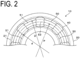
FIG. 2 is a plan view illustrating the ball bearing according to the embodiment of the present invention. -
FIG. 3 is a perspective view illustrating a retainer according to the embodiment of the present invention. - In
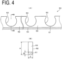
FIG. 4, (A) is a developed view illustrating the retainer according to the embodiment of the present invention. (B) is a cross-sectional view taken along line B-B of (A). -
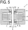
FIG. 5 is a cross-sectional view illustrating a motor according to an embodiment of the present invention. -
FIG. 6 is a cross-sectional view illustrating a motor according to another embodiment of the present invention. -
FIG. 7 is a perspective view illustrating a modification example of the embodiment of the present invention. -
FIG. 8 is a cross-sectional view for illustrating an angle β in a circumferential direction formed by a row of balls in an embodiment of the present invention. -
FIG. 1 is a cross-sectional view illustrating a ball bearing 10 according to an embodiment of the present invention. The ball bearing 10 shown in this drawing is configured such thatballs 40 are held at equal intervals by aretainer 50 between araceway groove 21 of anouter ring 20 and araceway groove 31 of aninner ring 30. - The
outer ring 20, theinner ring 30, and theballs 40 are made of materials such as martensitic stainless steels (SUS440C, and the like), high-carbon bearing steels (SUJ2, SAE52100, and the like), or ceramics (Si3N4, SiC, Al2O3, and the like), and surface hardness is increased to HRC58 or higher by heat treatment. Theretainer 50 is formed of a synthetic resin by injection molding or machining such as cutting. Here, for the purpose of reducing the centrifugal force of theball 40, it is preferable that the material constituting theball 40 is ceramics. - As shown in
FIGS. 3 and4 , theretainer 50 is a synthetic resin crown-shaped retainer. This retainer includes abase portion 51 having an annular shape and a plurality ofpockets 53 formed along a circumferential direction between a pair ofpillar portions 52 extending axially upward from thebase portion 51. Theballs 40 are fitted between the pair ofpillar portions 52. An inner periphery of thepocket 53 forms a cylindrical curved surface or a spherical surface having a diameter slightly larger than an outer diameter of theball 40. A tapered surface (thickness-reduced portion) 54 having an inner diameter gradually increasing toward an axial direction is formed at a corner portion at an inner peripheral surface side of theretainer 50. Such aretainer 50 is disposed so as to come into contact with an outerperipheral surface 32 of theinner ring 30. The outerperipheral surface 32 of theinner ring 30 is preferably a cylindrical curved surface parallel to a rotation axis over an entire region in the axial direction excluding theraceway groove 31 and end portions in the axial direction. With such a configuration, a contact area between theretainer 50 and the outerperipheral surface 32 of theinner ring 30 is secured, and local wear of theretainer 50 can be suppressed. It is preferable that there is no step portion of the outerperipheral surface 32. The step portion causes significant wear of theretainer 50 when theretainer 50 is deformed so as to be opened by centrifugal force. - Due to the
tapered surface 54, when thepillar portions 52 of theretainer 50 expand radially outward due to high-speed rotation of the ball bearing 10, end portions of thepillar portions 52 move toward theouter ring 20 side, while thebase portion 51 serving as roots of thepillar portions 52 moves toward theinner ring 30 side. In this case, the corner portion of thebase portion 51 may come into contact with the outer peripheral surface of theinner ring 30, but thebase portion 51 is formed with thetapered surface 54, thus making the contact area small even when the contact is made. Thetapered surface 54 and the outer peripheral surface of theinner ring 30 form a portion having a wedge-shaped cross section, and the lubricant is held in the portion by capillary action. Instead of thetapered surface 54, an R-shape having an arc-shaped cross section may be used. A boundary portion between thetapered surface 54 and an inner peripheral surface of thebase portion 51 may have an R-shape having an arc-shaped cross section. In this case, when thepillar portions 52 of theretainer 50 expand radially outward due to high-speed rotation of the ball bearing 10, a portion of theretainer 50 coming into contact with the outer peripheral surface of theinner ring 30 has an R-shape or a flat surface, making it possible to further reduce wear of theretainer 50. - If an angle α of the
tapered surface 54 with respect to the axial direction is too large, the rigidity of theretainer 50 is impaired, and therefore the angle α is set to be less than 45°. The angle α of thetapered surface 54 is preferably less than 30° and more preferably less than 15°. - A
tapered surface 22 having an inner diameter gradually increasing from an axial end portion of theraceway groove 21 toward the axial direction is formed on an inner peripheral surface of theouter ring 20 at an axial end portion side of thepillar portion 52. Even when thepillar portions 52 of theretainer 50 are deformed to open due to centrifugal force, thetapered surface 22 reduces contact of thepillar portions 52 with the inner peripheral surface of theouter ring 20. - An
annular groove 24 is formed in the vicinity of an opening portion of the inner peripheral surface of theouter ring 20. An edge portion of a seal member is fitted into thegroove 24. - As the synthetic resin constituting the
retainer 50, polyamide (nylon 66, nylon 46, PA9T, PA10T, and the like), polyacetal, or the like can be used, but polyetherketone-based resin such as polyetheretherketone (PEEK) is favorably used because of its high strength. Those thermoplastic resins reinforced with glass fibers or carbon fibers can be used. Such a synthetic resin is favorably molded into theretainer 50 by injection molding suitable for mass production. - In the ball bearing 10 of the present embodiment, in order to suppress deformation of the
retainer 50 due to centrifugal force accompanying high-speed rotation, the following dimensional ratios of the respective portions are set as a preferable aspect (seeFIG. 4B ). - i) A ratio of an axial thickness B of the
base portion 51 to an axial length A of theretainer 50 is equal to or greater than 20%, and a ratio of the axial thickness B to a radial thickness C of thebase portion 51 is equal to or greater than 52%. Setting in this way makes thebase portion 51 relatively long and reduces deformation due to the centrifugal force. The ratio of the thickness B to the length A is preferably 22% or greater, and the ratio of the thickness B to the thickness C is preferably 60% or greater. - ii) A ratio of a radial thickness of the
retainer 50 to the axial length A of theretainer 50 ranges from 30% to 40%. Setting in this way causes theretainer 50 to be thinned in the radial direction, thepillar portion 52 to be reduced in weight, and can reduce deformation due to the centrifugal force. Since sufficient strength cannot be obtained if theretainer 50 is too thin, the lower limit of the ratio of the thickness C to the length A is set to 30%. The ratio of the thickness C to the length A preferably ranges from 30% to 37.5%. - iii) A difference between an inner diameter D of the
outer ring 20 and an outer diameter d of theinner ring 30 is defined as a raceway groove-to-raceway groove distance (seeFIG. 2 ), a ratio of the radial thickness C of theretainer 50 to the raceway groove-to-raceway groove distance is 50% or greater and less than 65%. Setting in this way causes theretainer 50 to be thinned in the radial direction, thepillar portion 52 to be reduced in weight, and can reduce the circle diameter due to the centrifugal force. The ratio of the thickness C to the raceway groove-to-raceway groove distance is preferably 50% or greater and less than 62%. - iv) When a half of a difference between an outer diameter of the
outer ring 20 and an inner diameter of theinner ring 30 is defined as a radial thickness of theball bearing 10, a ratio of a diameter of theball 40 to the radial thickness of theball bearing 10 is 40% or greater and less than 50%, and a ratio of the diameter of theball 40 to the outer diameter of theouter ring 20 is 10% or greater and less than 20%. Setting in this way makes the size of theball 40 small with respect to the size of theball bearing 10 and reduces the centrifugal force of theball 40. This makes it possible to reduce wear of theraceway groove 21 of theouter ring 20. The ratio of the diameter of theball 40 to the radial thickness of theball bearing 10 is preferably 40% or greater and less than 45%. The number ofballs 40 can be increased by reducing the size of theballs 40. - v) In an axial view when the
balls 40 incorporated between theouter ring 20 and theinner ring 30 as shown inFIG. 8 are arranged continuous in the circumferential direction without a gap, an angle β (incorporation angle) between theballs 40 sides formed by a straight line passing through a center axis of theouter ring 20 and a center of aball 40 at one end of a row of theballs 40 and a straight line passing through the center axis of theouter ring 20 and a center of aball 40 at the other end of the row of theballs 40 ranges from 185° to 195°. By setting the incorporation angle large in this way, the number ofballs 40 can be increased and the diameter of theballs 40 can be reduced. Thus, a pitch circle diameter P is reduced, the centrifugal force of theballs 40 is reduced, and the centrifugal force acting on theretainer 50 is reduced. When the incorporation angle ranges from 185° to 195°, a width in the circumferential direction of thepillar portion 52 of theretainer 50 is inevitably reduced, and the pillar portion is reduced in weight, resulting in further reduction in the centrifugal force. The incorporation angle β preferably ranges from 185° to 190°. - vi) As shown in
FIG. 1 , a radial depth of theraceway groove 31 of theinner ring 30 is greater than a radial depth of theraceway groove 21 of the outer ring 20 (seeFIG. 1 ). Setting in this way allows theballs 40 to be disposed at the inner side in the radial direction and the centrifugal force of theballs 40 to be reduced. - vii) A groove curvature ratio of the diameter of the
ball 40 to a radius of curvature of cross sections of theraceway grooves outer ring 20 and theinner ring 30 is 53% or greater. Setting in this way reduces the contact between theball 40 and theraceway grooves raceway groove 31 of theinner ring 30 is made deeper than the depth of theraceway groove 21 of theouter ring 20, the groove curvature ratio of the cross section of theraceway groove 31 of theinner ring 30 is made larger than the groove curvature ratio of the cross section of theraceway groove 21 of theouter ring 20 so as to reduce the contact between theball 40 and theraceway groove 31. - A motor 1 mounted with the
ball bearing 10 having the above-described configuration will be described with reference toFIG. 5 . - The motor 1 includes a
housing 2. Thehousing 2 includes therein aspace 2a having a circular axial cross section, and astator core 3 is fixed to an inner peripheral surface of thespace 2a. Thestator core 3 is formed by layering, in the axial direction, a plurality of thin sheet-like soft magnetic materials (for example, electromagnetic steel sheets) having an annular shape, and includes a plurality of pole teeth protruding outward in the radial direction. The plurality of pole teeth are provided at equal intervals along a circumferential direction, and acoil 4 is wound around each pole teeth. -
Opening portions 2b are formed in both end surfaces of thehousing 2, and theball bearings 10 having the above-described configuration are fixed to the openingportions 2b with an adhesive. Ashaft 5 is fixed to theinner rings 30 of theball bearings 10 by an adhesive, so that theshaft 5 is rotatably supported by theball bearings 10. - A rotor magnet (rotor core) 7 is fixed to an intermediate portion of the
shaft 5 between theball bearings 10 via aspacer 6 by a means such as press-fitting or adhesion. Therotor magnet 7 faces the pole teeth of thestator core 3 with a gap and is magnetized in a manner such that adjacent portions alternately have opposing magnetic poles such as S-N-S-N... along a circumferential direction. Supplying thecoil 4 with a drive current generates a driving force rotating therotor magnet 7, thereby rotating theshaft 5 with respect to thehousing 2. A rotary body such as a dryer is connected to a distal end portion of theshaft 5. - In the motor 1 having the above-described configuration, since the
shaft 5 is rotatably supported by theball bearing 10 and theretainer 50 is in contact with theinner ring 30, the centrifugal force acting on theretainer 50 can be reduced. In addition, theretainer 50 is less likely to come into contact with theouter ring 20 when expanding radially outward due to high-speed rotation. On the other hand, since the tapered surface having an inner diameter gradually increasing toward the axial direction is provided at the corner portion at the inner peripheral surface side of thebase portion 51 of theretainer 50, the contact area of theretainer 50 with theinner ring 30 is small. When thepillar portions 52 of theretainer 50 are inclined radially outward and thebase portion 51 is moved inward, the contact area between thebase portion 51 and theinner ring 30 is kept small. Thus, wear of theretainer 50 can be suppressed. - Accordingly, the motor 1 having the above-described configuration allows for rotation with a dmn value of 17 × 105 to 21 × 105.
- As a result of performing a durability test on the
ball bearing 10 of the embodiment having the above-described dmn value, the test could be continued for 1000 hours or longer. In contrast, as a result of performing a durability test on a ball bearing not having the above-described characteristics, the test was stopped after about 200 hours. - The present invention is not limited to the embodiment described above, and it is possible to make various modifications as described below.
- i) As shown in
FIG. 7 , holdingclaws 55 can be formed at both end portions of thepillar portion 52. The holdingclaws 55 extend from the end portions of theadjacent pillar portions 52 toward the upper side in the axial direction and toward each other. Thepocket 53 in this case is a spherical curved surface. In this example as well, all of the various numerical limitations described above apply. - ii) As shown in
FIG. 1B , anannular groove 23 may be formed in the outer periphery of theouter ring 20, and an O-ring may be mounted in theannular groove 23. - iii) Although the motor shown in
FIG. 5 is an example of therotor magnet 7 supported at both ends between theball bearings 10, therotor magnet 7 may be supported in a cantilever manner by theball bearings 10 as shown inFIG. 6 . In amotor 1a shown inFIG. 6 , acasing 8 for accommodating theball bearings 10 is provided on an end surface of thehousing 2. Although thecasing 8 is formed integrally with thehousing 2, the casing and the housing may be formed separately and fixed to each other by a means such as bonding. Thecasing 8 has a cylindrical shape, and one of theball bearings 10 is fixed to a lower end portion of an inner peripheral surface 8a of the casing by a means such as bonding. Aspacer 9 is in contact with theinner ring 30 of theball bearing 10, and theother ball bearing 10 is fixed to the inner peripheral surface 8a in a state where theinner ring 30 is in contact with an upper end surface of thespacer 9. Thus, even in themotor 1a with therotor magnet 7 supported in a cantilever manner, it is possible to obtain the action and effect equivalent to those of the motor 1. - The ball bearing of the present invention can be suitably used by being incorporated into various high-speed rotating devices such as motors and electric tools used in household vacuum cleaners and dryers, fan motors, and dental handpieces, and head actuators of hard disk drive devices swinging at high speed.
- 1, 1a: motor, 2: housing, 2a: space, 2b: opening portion, 3: stator core, 4: coil, 5: shaft, 6: spacer, 7: rotor magnet (rotor core), 8: casing, 8a: inner peripheral surface, 9: spacer, 10: ball bearing, 20: outer ring, 21: raceway groove, 22: tapered surface, 23: annular groove, 24: groove, 30: inner ring, 31: raceway groove, 32: outer peripheral surface, 40: ball, 50: retainer, 51: base portion, 52: pillar portion, 53: pocket, 54: tapered surface (thickness-reduced portion), 55: holding claw, α: angle, A: axial length, B: axial thickness, C: radial thickness, d: outer diameter of inner ring, D: inner diameter of outer ring, P: pitch circle diameter.
Claims (15)
- A ball bearing, comprising:an inner ring including a raceway groove;an outer ring including a raceway groove;a plurality of balls disposed between the raceway grooves; anda retainer having a crown shape to be inserted between the balls, whereinthe retainer comprises a base portion having an annular shape, a pair of pillar portions extending from the base portion in an axial direction, and a plurality of pockets formed along a circumferential direction, the balls being fitted between the pillar portions,the retainer comes into contact with the inner ring, anda thickness-reduced portion having an inner diameter gradually increasing toward the axial direction is provided at a corner portion at an inner peripheral surface side of the base portion.
- The ball bearing according to claim 1, whereinthe thickness-reduced portion is a tapered surface, andan angle formed by the tapered surface with respect to the axial direction is less than 45°.
- The ball bearing according to claim 2, whereinthe thickness-reduced portion is a tapered surface, andan angle formed by the tapered surface with respect to the axial direction is less than 30°.
- The ball bearing according to claim 3, whereinthe thickness-reduced portion is a tapered surface, andan angle formed by the tapered surface with respect to the axial direction is less than 15°.
- The ball bearing according to any one of claims 1 to 4, whereina ratio of an axial thickness of the base portion to an axial length of the retainer is 20% or greater, anda ratio of the axial thickness to a radial thickness of the base portion is 52% or greater.
- The ball bearing according to any one of claims 1 to 5, wherein a ratio of a radial thickness of the base portion to an axial length of the retainer ranges from 30% to 40%.
- The ball bearing according to any one of claims 1 to 6, whereina difference between an inner diameter of the outer ring and an outer diameter of the inner ring is defined as a raceway groove-to-raceway groove distance, anda ratio of a radial thickness of the retainer to the raceway groove-to-raceway groove distance is 50% or greater and less than 65%.
- The ball bearing according to any one of claims 1 to 7, whereina half of a difference between an outer diameter of the outer ring and an inner diameter of the inner ring is defined as a radial thickness of a bearing,a ratio of a diameter of the ball to the radial thickness of the bearing is 40% or greater and less than 50%, anda ratio of the diameter of the ball to the outer diameter of the outer ring is 10% or greater and less than 20%.
- The ball bearing according to claim 8, wherein in an axial view when the balls incorporated between the outer ring and the inner ring are arranged continuous in the circumferential direction without a gap, an angle in the circumferential direction between sides of the balls formed by a straight line passing through a center axis of the outer ring and a center of a ball at one end of a row of the balls and a straight line passing through the center axis of the outer ring and a center of a ball at the other end of the row of the balls ranges from 185° to 195°.
- The ball bearing according to any one of claims 1 to 9, wherein a radial depth of the raceway groove of the inner ring is larger than a radial depth of the raceway groove of the outer ring.
- The ball bearing according to any one of claims 1 to 10, wherein an entire circumference of an outer peripheral surface of the inner ring excluding the raceway groove is a cylindrical curved surface parallel to the axial direction.
- The ball bearing according to any one of claims 1 to 11, whereina groove curvature ratio of a diameter of the balls to a radius of curvature of cross sections of the raceway grooves of the outer ring and the inner ring is 53% or greater, andthe groove curvature ratio of the cross section of the raceway groove of the inner ring is larger than the groove curvature ratio of the cross section of the raceway groove of the outer ring.
- The ball bearing according to any one of claims 1 to 12, wherein a tapered surface having an inner diameter gradually increasing from an axial end portion of the raceway groove toward the axial direction is provided on an inner peripheral surface of the outer ring at an axial end portion side of the pillar portion.
- The ball bearing according to any one of claims 1 to 13, wherein a dmn value ranges from 17 × 105 to 21 × 105.
- A motor, comprising:a shaft rotatably provided via a ball bearing described in any one of claims 1 to 14; anda rotor core fixed to the shaft.
Applications Claiming Priority (2)
| Application Number | Priority Date | Filing Date | Title |
|---|---|---|---|
| JP2022072960 | 2022-04-27 | ||
| PCT/JP2023/003697 WO2023210092A1 (en) | 2022-04-27 | 2023-02-06 | Ball bearing |
Publications (2)
| Publication Number | Publication Date |
|---|---|
| EP4517120A1 true EP4517120A1 (en) | 2025-03-05 |
| EP4517120A4 EP4517120A4 (en) | 2026-04-01 |
Family
ID=87563263
Family Applications (1)
| Application Number | Title | Priority Date | Filing Date |
|---|---|---|---|
| EP23795840.0A Pending EP4517120A4 (en) | 2022-04-27 | 2023-02-06 | Ball bearing |
Country Status (4)
| Country | Link |
|---|---|
| EP (1) | EP4517120A4 (en) |
| JP (1) | JP7326648B1 (en) |
| KR (1) | KR20240162093A (en) |
| CN (1) | CN119032225A (en) |
Family Cites Families (12)
| Publication number | Priority date | Publication date | Assignee | Title |
|---|---|---|---|---|
| GB190312206A (en) * | 1903-05-28 | 1904-03-24 | William Phillips Thompson | Improvements in Ball Bearings. |
| JP3535898B2 (en) * | 1994-10-20 | 2004-06-07 | 光洋精工株式会社 | Crown cage |
| JPH1019045A (en) * | 1996-07-03 | 1998-01-20 | Koyo Seiko Co Ltd | Deep groove ball bearing and supercharger employing it |
| JP2003021148A (en) * | 2001-07-05 | 2003-01-24 | Nsk Ltd | Ball bearing |
| EP1553316B1 (en) * | 2002-07-12 | 2011-07-27 | Nsk Ltd. | Pulley support double row ball bearing |
| DE102006030836B4 (en) * | 2006-07-04 | 2012-03-01 | Gebrüder Reinfurt GmbH & Co. KG | Rolling bearing cage |
| JP2008095912A (en) * | 2006-10-16 | 2008-04-24 | Ntn Corp | Alternator bearing |
| WO2010067852A1 (en) * | 2008-12-10 | 2010-06-17 | 日本精工株式会社 | Ball bearing, and transmission for hybrid vehicle |
| JP2017075683A (en) | 2015-10-16 | 2017-04-20 | 日本精工株式会社 | Crown type holder |
| US11221044B2 (en) * | 2019-10-01 | 2022-01-11 | Jtekt Corporation | Rolling bearing |
| JP2021063530A (en) * | 2019-10-11 | 2021-04-22 | 株式会社ジェイテクト | Rolling bearing |
| JP2022036002A (en) * | 2020-08-19 | 2022-03-04 | Ntn株式会社 | Ball bearing |
-
2023
- 2023-02-06 CN CN202380033578.4A patent/CN119032225A/en active Pending
- 2023-02-06 EP EP23795840.0A patent/EP4517120A4/en active Pending
- 2023-02-06 JP JP2023527811A patent/JP7326648B1/en active Active
- 2023-02-06 KR KR1020247033620A patent/KR20240162093A/en active Pending
Also Published As
| Publication number | Publication date |
|---|---|
| KR20240162093A (en) | 2024-11-14 |
| EP4517120A4 (en) | 2026-04-01 |
| CN119032225A (en) | 2024-11-26 |
| JPWO2023210092A1 (en) | 2023-11-02 |
| JP7326648B1 (en) | 2023-08-15 |
Similar Documents
| Publication | Publication Date | Title |
|---|---|---|
| KR100646807B1 (en) | Motor and magnetic bearing assembly thereof | |
| JP4209412B2 (en) | Artificial heart pump | |
| JP4523962B2 (en) | Artificial heart pump | |
| CN107809151B (en) | Motor rotor with extended shoulder for bearing | |
| JP4611364B2 (en) | Artificial heart pump | |
| JP4611365B2 (en) | Artificial heart pump | |
| TWI776014B (en) | Ball bearing cage and ball bearing | |
| JPH10238535A (en) | Spindle motor for disk | |
| US7364365B2 (en) | Conrad bearing cage | |
| AU2014273308B2 (en) | Electro-magnetic bearing assembly with inner ventilation to cool the bearing | |
| US6040644A (en) | Shaft for a motor-driven spindle | |
| EP1048863A3 (en) | Spindle motor and complex bearing assembly for use with the spindle motor | |
| JP2011185385A (en) | Rolling bearing and crown type cage | |
| JP7326648B1 (en) | ball bearing | |
| WO2023210092A1 (en) | Ball bearing | |
| CN118234964A (en) | Mechanical roller bearings | |
| JP5499327B2 (en) | Rolling bearing | |
| JP2002122147A (en) | Ball bearing and its manufacturing method | |
| KR20010072804A (en) | Pure Rolling Bearing | |
| JP2000161365A (en) | Crown type cage, ball bearing and rotating machinery | |
| KR940010450A (en) | Bearing device | |
| JP2007298164A (en) | Crown type cage and ball bearing | |
| JP2014202247A (en) | Resin comb-shaped cage for double row roller bearing, and double row roller bearing | |
| CN118815830A (en) | Rolling bearing cage, rolling bearing, vehicle and assembly method | |
| JP4752616B2 (en) | Ball bearing |
Legal Events
| Date | Code | Title | Description |
|---|---|---|---|
| STAA | Information on the status of an ep patent application or granted ep patent |
Free format text: STATUS: THE INTERNATIONAL PUBLICATION HAS BEEN MADE |
|
| PUAI | Public reference made under article 153(3) epc to a published international application that has entered the european phase |
Free format text: ORIGINAL CODE: 0009012 |
|
| STAA | Information on the status of an ep patent application or granted ep patent |
Free format text: STATUS: REQUEST FOR EXAMINATION WAS MADE |
|
| 17P | Request for examination filed |
Effective date: 20241015 |
|
| AK | Designated contracting states |
Kind code of ref document: A1 Designated state(s): AL AT BE BG CH CY CZ DE DK EE ES FI FR GB GR HR HU IE IS IT LI LT LU LV MC ME MK MT NL NO PL PT RO RS SE SI SK SM TR |
|
| DAV | Request for validation of the european patent (deleted) | ||
| DAX | Request for extension of the european patent (deleted) | ||
| P01 | Opt-out of the competence of the unified patent court (upc) registered |
Free format text: CASE NUMBER: UPC_APP_0003839_4517120/2026 Effective date: 20260203 |
|
| A4 | Supplementary search report drawn up and despatched |
Effective date: 20260304 |
|
| RIC1 | Information provided on ipc code assigned before grant |
Ipc: F16C 19/06 20060101AFI20260226BHEP Ipc: F16C 33/41 20060101ALI20260226BHEP Ipc: F16C 33/38 20060101ALI20260226BHEP Ipc: F16C 33/58 20060101ALI20260226BHEP Ipc: F16C 43/06 20060101ALI20260226BHEP Ipc: H02K 5/173 20060101ALI20260226BHEP Ipc: F16C 33/78 20060101ALN20260226BHEP |