EP4517118A1 - Method of producing a sliding surface of a sliding bearing by additive manufacturing - Google Patents
Method of producing a sliding surface of a sliding bearing by additive manufacturing Download PDFInfo
- Publication number
- EP4517118A1 EP4517118A1 EP23190764.3A EP23190764A EP4517118A1 EP 4517118 A1 EP4517118 A1 EP 4517118A1 EP 23190764 A EP23190764 A EP 23190764A EP 4517118 A1 EP4517118 A1 EP 4517118A1
- Authority
- EP
- European Patent Office
- Prior art keywords
- sliding surface
- bearing
- sliding
- additive manufacturing
- layer
- Prior art date
- Legal status (The legal status is an assumption and is not a legal conclusion. Google has not performed a legal analysis and makes no representation as to the accuracy of the status listed.)
- Withdrawn
Links
Images

Classifications
-
- F—MECHANICAL ENGINEERING; LIGHTING; HEATING; WEAPONS; BLASTING
- F16—ENGINEERING ELEMENTS AND UNITS; GENERAL MEASURES FOR PRODUCING AND MAINTAINING EFFECTIVE FUNCTIONING OF MACHINES OR INSTALLATIONS; THERMAL INSULATION IN GENERAL
- F16C—SHAFTS; FLEXIBLE SHAFTS; ELEMENTS OR CRANKSHAFT MECHANISMS; ROTARY BODIES OTHER THAN GEARING ELEMENTS; BEARINGS
- F16C17/00—Sliding-contact bearings for exclusively rotary movement
- F16C17/02—Sliding-contact bearings for exclusively rotary movement for radial load only
- F16C17/03—Sliding-contact bearings for exclusively rotary movement for radial load only with tiltably-supported segments, e.g. Michell bearings
-
- B—PERFORMING OPERATIONS; TRANSPORTING
- B29—WORKING OF PLASTICS; WORKING OF SUBSTANCES IN A PLASTIC STATE IN GENERAL
- B29C—SHAPING OR JOINING OF PLASTICS; SHAPING OF MATERIAL IN A PLASTIC STATE, NOT OTHERWISE PROVIDED FOR; AFTER-TREATMENT OF THE SHAPED PRODUCTS, e.g. REPAIRING
- B29C64/00—Additive manufacturing, i.e. manufacturing of three-dimensional [3D] objects by additive deposition, additive agglomeration or additive layering, e.g. by 3D printing, stereolithography or selective laser sintering
- B29C64/10—Processes of additive manufacturing
- B29C64/106—Processes of additive manufacturing using only liquids or viscous materials, e.g. depositing a continuous bead of viscous material
- B29C64/118—Processes of additive manufacturing using only liquids or viscous materials, e.g. depositing a continuous bead of viscous material using filamentary material being melted, e.g. fused deposition modelling [FDM]
-
- B—PERFORMING OPERATIONS; TRANSPORTING
- B29—WORKING OF PLASTICS; WORKING OF SUBSTANCES IN A PLASTIC STATE IN GENERAL
- B29C—SHAPING OR JOINING OF PLASTICS; SHAPING OF MATERIAL IN A PLASTIC STATE, NOT OTHERWISE PROVIDED FOR; AFTER-TREATMENT OF THE SHAPED PRODUCTS, e.g. REPAIRING
- B29C64/00—Additive manufacturing, i.e. manufacturing of three-dimensional [3D] objects by additive deposition, additive agglomeration or additive layering, e.g. by 3D printing, stereolithography or selective laser sintering
- B29C64/30—Auxiliary operations or equipment
- B29C64/35—Cleaning
-
- B—PERFORMING OPERATIONS; TRANSPORTING
- B33—ADDITIVE MANUFACTURING TECHNOLOGY
- B33Y—ADDITIVE MANUFACTURING, i.e. MANUFACTURING OF THREE-DIMENSIONAL [3D] OBJECTS BY ADDITIVE DEPOSITION, ADDITIVE AGGLOMERATION OR ADDITIVE LAYERING, e.g. BY 3D PRINTING, STEREOLITHOGRAPHY OR SELECTIVE LASER SINTERING
- B33Y10/00—Processes of additive manufacturing
-
- B—PERFORMING OPERATIONS; TRANSPORTING
- B33—ADDITIVE MANUFACTURING TECHNOLOGY
- B33Y—ADDITIVE MANUFACTURING, i.e. MANUFACTURING OF THREE-DIMENSIONAL [3D] OBJECTS BY ADDITIVE DEPOSITION, ADDITIVE AGGLOMERATION OR ADDITIVE LAYERING, e.g. BY 3D PRINTING, STEREOLITHOGRAPHY OR SELECTIVE LASER SINTERING
- B33Y80/00—Products made by additive manufacturing
-
- F—MECHANICAL ENGINEERING; LIGHTING; HEATING; WEAPONS; BLASTING
- F16—ENGINEERING ELEMENTS AND UNITS; GENERAL MEASURES FOR PRODUCING AND MAINTAINING EFFECTIVE FUNCTIONING OF MACHINES OR INSTALLATIONS; THERMAL INSULATION IN GENERAL
- F16C—SHAFTS; FLEXIBLE SHAFTS; ELEMENTS OR CRANKSHAFT MECHANISMS; ROTARY BODIES OTHER THAN GEARING ELEMENTS; BEARINGS
- F16C33/00—Parts of bearings; Special methods for making bearings or parts thereof
- F16C33/02—Parts of sliding-contact bearings
- F16C33/04—Brasses; Bushes; Linings
- F16C33/20—Sliding surface consisting mainly of plastics
- F16C33/201—Composition of the plastic
-
- F—MECHANICAL ENGINEERING; LIGHTING; HEATING; WEAPONS; BLASTING
- F16—ENGINEERING ELEMENTS AND UNITS; GENERAL MEASURES FOR PRODUCING AND MAINTAINING EFFECTIVE FUNCTIONING OF MACHINES OR INSTALLATIONS; THERMAL INSULATION IN GENERAL
- F16C—SHAFTS; FLEXIBLE SHAFTS; ELEMENTS OR CRANKSHAFT MECHANISMS; ROTARY BODIES OTHER THAN GEARING ELEMENTS; BEARINGS
- F16C33/00—Parts of bearings; Special methods for making bearings or parts thereof
- F16C33/02—Parts of sliding-contact bearings
- F16C33/04—Brasses; Bushes; Linings
- F16C33/20—Sliding surface consisting mainly of plastics
- F16C33/208—Methods of manufacture, e.g. shaping, applying coatings
-
- F—MECHANICAL ENGINEERING; LIGHTING; HEATING; WEAPONS; BLASTING
- F16—ENGINEERING ELEMENTS AND UNITS; GENERAL MEASURES FOR PRODUCING AND MAINTAINING EFFECTIVE FUNCTIONING OF MACHINES OR INSTALLATIONS; THERMAL INSULATION IN GENERAL
- F16C—SHAFTS; FLEXIBLE SHAFTS; ELEMENTS OR CRANKSHAFT MECHANISMS; ROTARY BODIES OTHER THAN GEARING ELEMENTS; BEARINGS
- F16C2208/00—Plastics; Synthetic resins, e.g. rubbers
- F16C2208/02—Plastics; Synthetic resins, e.g. rubbers comprising fillers, fibres
-
- F—MECHANICAL ENGINEERING; LIGHTING; HEATING; WEAPONS; BLASTING
- F16—ENGINEERING ELEMENTS AND UNITS; GENERAL MEASURES FOR PRODUCING AND MAINTAINING EFFECTIVE FUNCTIONING OF MACHINES OR INSTALLATIONS; THERMAL INSULATION IN GENERAL
- F16C—SHAFTS; FLEXIBLE SHAFTS; ELEMENTS OR CRANKSHAFT MECHANISMS; ROTARY BODIES OTHER THAN GEARING ELEMENTS; BEARINGS
- F16C2208/00—Plastics; Synthetic resins, e.g. rubbers
- F16C2208/20—Thermoplastic resins
- F16C2208/36—Polyarylene ether ketones [PAEK], e.g. PEK, PEEK
-
- F—MECHANICAL ENGINEERING; LIGHTING; HEATING; WEAPONS; BLASTING
- F16—ENGINEERING ELEMENTS AND UNITS; GENERAL MEASURES FOR PRODUCING AND MAINTAINING EFFECTIVE FUNCTIONING OF MACHINES OR INSTALLATIONS; THERMAL INSULATION IN GENERAL
- F16C—SHAFTS; FLEXIBLE SHAFTS; ELEMENTS OR CRANKSHAFT MECHANISMS; ROTARY BODIES OTHER THAN GEARING ELEMENTS; BEARINGS
- F16C2220/00—Shaping
- F16C2220/24—Shaping by built-up welding
-
- F—MECHANICAL ENGINEERING; LIGHTING; HEATING; WEAPONS; BLASTING
- F16—ENGINEERING ELEMENTS AND UNITS; GENERAL MEASURES FOR PRODUCING AND MAINTAINING EFFECTIVE FUNCTIONING OF MACHINES OR INSTALLATIONS; THERMAL INSULATION IN GENERAL
- F16C—SHAFTS; FLEXIBLE SHAFTS; ELEMENTS OR CRANKSHAFT MECHANISMS; ROTARY BODIES OTHER THAN GEARING ELEMENTS; BEARINGS
- F16C2360/00—Engines or pumps
- F16C2360/31—Wind motors
Definitions
- the present invention relates to a method of producing a sliding surface of a sliding bearing by an additive manufacturing process resulting in an additive manufacturing sliding surface.
- the present invention further relates to a sliding bearing comprising a sliding surface is obtainable by said method.
- Wind turbines are increasingly used for the generation of electrical energy.
- a wind turbine comprises a tower and a nacelle mounted on the tower, to which a hub is attached.
- a blade rotor is mounted at the hub and coupled to a generator.
- a plurality of blades extends from the blade rotor. The blades are oriented in such a way that wind passing over the blades turns the blade rotor, thereby driving the generator. Hence, the rotational energy of the blades is transferred to the generator rotor as part of the generator, which then converts the mechanical energy into electricity and transfers the electricity to the electrical grid.
- the generator and other parts of the drive train are mounted with at least one bearing.
- This bearing allows the drive train to rotate. At the same time it provides the necessary stability by supporting the radial and axial loads and the bending moments present in the drive train.
- WO 2011/003482 A2 describes a wind turbine main bearing realized to bear a shaft of a wind turbine.
- the bearing comprises a sliding bearing with a plurality of bearing pads.
- Sliding bearings known in the art typically comprise a bearing base body of a metallic material, to which is applied a sliding bearing layer either directly or indirectly via an intermediate layer.
- the sliding bearing layer in particular the one of the bearing pads, is a sheet of extruded material hot pressed against a support structure that is prepared for mechanical and/or chemical bounding.
- the fiber orientation of the sliding bearing layer if a fiber material is used, depends on the extrusion process.
- a method of producing a sliding surface of a sliding bearing by an additive manufacturing process resulting in an additive manufacturing sliding surface comprises the steps of providing a surface on which the additive manufacturing sliding surface material is to be printed, building up the additive manufacturing sliding surface by successively adding material, thereby creating a sliding surface layer, and cleaning the sliding surface layer from excess material.
- the method further comprises the step of pressing the sliding surface layer to squeeze it.
- the pressing process compresses the structure of the printed layer, thus resulting in a more robust and stable sliding surface.
- each layer or print line can be varied in such a way that the sliding and structural properties of the sliding surface layer are optimized.
- pretreatment of the base structure is advantageous.
- a first layer of printed material is printed in such a way that it results in a mechanical connection to the support structure of the bearing shell. For example, a pattern of dow tails are machined into the support structure.
- the step of creating a sliding surface layer is repeated to create a plurality of sliding surface layers arranged on top of each other.
- each sliding surface layer has a different orientation. This allows to optimize the support of the bearing shells and the rotational movement.
- the added material comprises polyether ether ketone fibers. This material is particularly suitable for sliding surfaces of sliding bearings.
- the additive manufacturing sliding surface comprises a printed pattern of printed pattern of bars, in particular substantially circular bars or hexagon bars.
- Round or circular bars provide a stable structure and makes it easy to print multiple layers on top of each other.
- the additive manufacturing sliding surface comprises a plurality of printed patterns of substantially circular bars arranged on top of each other, wherein each layer of printed patterns of substantially circular bars is rotated with respect to the neighboring layer by degrees.
- the additive manufacturing process is 3D printing.
- the fiber orientation usually depends on the pattern in which layers of 3D printed material are processed.
- the printing pattern can be any pattern which gives an optimal structural performance and can be two dimensional, tree dimensioal or even processed in a 5-axis process.
- Yet another aspect of the invention relates to a sliding bearing for a wind turbine comprising a first bearing shell, a second bearing shell and a plurality of bearing pads arranged between first and the second bearing shell, wherein the bearing pads are connected to the second bearing shell and comprise a bearing pad sliding surface, wherein the first bearing shell comprises a first bearing shell sliding surface arranged so that the bearing pad sliding surface can slide along the bearing shell sliding surface when the bearing shells are moved in respect to each other, wherein the first bearing shell sliding surface and/or the bearing pad sliding surface is obtainable by the method of producing a sliding surface of a sliding bearing by an additive manufacturing process resulting in an additive manufacturing sliding surface.
- the additive manufacturing sliding surface is arranged on a support structure.
- the additive manufacturing sliding surface is coupled to the support structure by means of an adhesion layer.
- the adhesion layer comprises a chemically binding composition.
- the adhesion layer comprises a mechanically binding structure or fastening elements.
- the bearing pads are tilting pads tiltably mounted on the second bearing shell.
- the tilting pads are tiltably arranged one after another along a circumferential direction at the bearing shell.
- the multiplicity of tilting pads is tiltably mounted on the bearing body and, with the other bearing shell, forms a lubricated bearing gap.
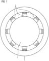
- Figure 1 shows a sliding bearing comprising a first bearing shell 1, a second bearing shell 2 and a plurality of bearing pads 3 arranged between first and the second bearing shell 1, 2.
- the bearing pads 3 are connected to the second bearing shell 2 and comprise a bearing pad sliding surface 5, which is not visible in the Figure.
- Figures 2 to 5 show bearing pads 3 comprising an additive manufacturing sliding surface 8 in different configurations.
- the additive manufacturing sliding surface 8 comprises a layer of single integral columns extending in radial direction of the sliding bearing.
- the columns are spaced apart to fill them with lubricant and/or allow lubricant to flow between the columns and improve the lubrication.
- the lubricant allows the debris of the manufacturing process to be removed.
- the additive manufacturing sliding surface 8 comprises a layer of single columns formed by a plurality of elliptic bars extending in radial direction of the sliding bearing.
- the columns are spaced apart to allow lubricant to flow between the columns and improve the lubrication.
- This type of columns can be produced by starting with the integral columns as shown in Figure 2 and pressing and/or heating the columns and subsequently adding a further layer of columns on top of the pressed columns, and repeating the process until a plurality of layers is achieved.
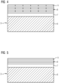
- Figures 4 and 5 show a multilayer sliding surface 8 comprising a plurality of substantially circular bar layers 11 pressed together.
- each layer of printed patterns of substantially circular bars 11 is rotated with respect to the neighboring layer by 90 degrees.
- all substantially circular bars 11 have the same orientation.
Landscapes
- Engineering & Computer Science (AREA)
- General Engineering & Computer Science (AREA)
- Chemical & Material Sciences (AREA)
- Manufacturing & Machinery (AREA)
- Materials Engineering (AREA)
- Mechanical Engineering (AREA)
- Physics & Mathematics (AREA)
- Optics & Photonics (AREA)
- Fluid Mechanics (AREA)
- Sliding-Contact Bearings (AREA)
Abstract
The present invention relates to a method of producing a sliding surface of a sliding bearing by an additive manufacturing process resulting in an additive manufacturing sliding surface. According to the invention, the method comprises the steps of providing a surface on which the additive manufacturing sliding surface material is to be printed, building up the additive manufacturing sliding surface by successively adding material, thereby creating a sliding surface layer, and cleaning the sliding surface layer from excess material.
Description
- The present invention relates to a method of producing a sliding surface of a sliding bearing by an additive manufacturing process resulting in an additive manufacturing sliding surface. The present invention further relates to a sliding bearing comprising a sliding surface is obtainable by said method.
- Wind turbines are increasingly used for the generation of electrical energy. A wind turbine comprises a tower and a nacelle mounted on the tower, to which a hub is attached. A blade rotor is mounted at the hub and coupled to a generator. A plurality of blades extends from the blade rotor. The blades are oriented in such a way that wind passing over the blades turns the blade rotor, thereby driving the generator. Hence, the rotational energy of the blades is transferred to the generator rotor as part of the generator, which then converts the mechanical energy into electricity and transfers the electricity to the electrical grid.
- To allow the rotational movement for driving the generator and to provide the necessary stability of the rotating parts, the generator and other parts of the drive train are mounted with at least one bearing. This bearing allows the drive train to rotate. At the same time it provides the necessary stability by supporting the radial and axial loads and the bending moments present in the drive train.
-
WO 2011/003482 A2 describes a wind turbine main bearing realized to bear a shaft of a wind turbine. The bearing comprises a sliding bearing with a plurality of bearing pads. - Sliding bearings known in the art typically comprise a bearing base body of a metallic material, to which is applied a sliding bearing layer either directly or indirectly via an intermediate layer. The sliding bearing layer, in particular the one of the bearing pads, is a sheet of extruded material hot pressed against a support structure that is prepared for mechanical and/or chemical bounding. Through this process, the fiber orientation of the sliding bearing layer, if a fiber material is used, depends on the extrusion process.
- Although sliding bearings known in the art have good properties with regard to desired sliding properties and desired wear resistance, there is a need for further improving their properties.
- However, there is either the problem that the sliding bearing layer does not provide the desired sliding bearing properties or the method for producing such a sliding bearing is too expensive.
- The current development of the technology of wind turbines tends to an increased size of wind turbines for harvesting more wind energy, with longer blades and higher towers. As more energy is produced, the size and weight of the drive train components, i.e., the gearbox, the generator or the power electronics, and the components connected to the drive train components have increased in size as well. This increased size of wind turbine components results in the need to improve the bearing parts, as they have to be able to transfer the loads in the drive train. Hence, there is a need for the main bearing to adapt to the fast growth of the wind turbine.
- It is thus an object for the invention to provide a new type of sliding bearing with improved properties and a method for the simple production of the sliding bearing.
- This is achieved by a method of producing a sliding surface of a sliding bearing by an additive manufacturing process resulting in an additive manufacturing sliding surface according to claim 1 and by a sliding bearing comprising a sliding surface obtainable by said method according to claim 10.
- According to the invention, a method of producing a sliding surface of a sliding bearing by an additive manufacturing process resulting in an additive manufacturing sliding surface comprises the steps of providing a surface on which the additive manufacturing sliding surface material is to be printed, building up the additive manufacturing sliding surface by successively adding material, thereby creating a sliding surface layer, and cleaning the sliding surface layer from excess material.
- The sliding surface layer is thus produced by means of additive manufacturing, in particular by means of 3-D printing. This process gives unique properties to the sliding surface layer, not achievable through other manufacturing processes due to the accuracy of the printing techniques. The additive manufacturing or a 3-D printing or the construction in layers by a sintering method provides an optimum possibility of producing a suitable sliding surface since the production process is subject only to the peripheral conditions of the production of the additive manufacturing and in this way the sliding surface can be formed correspondingly complex. The accessibility of tools to the internal geometry no longer has any influence.
- According to a preferred embodiment of the invention, the method further comprises the step of pressing the sliding surface layer to squeeze it. The pressing process compresses the structure of the printed layer, thus resulting in a more robust and stable sliding surface.
- According to another preferred embodiment of the invention, the method further comprises the step of heating the sliding surface layer during the step of pressing the sliding surface layer.
- The fiber orientation depends on the processing parameters of the 3D printing or the additive manufacturing process. Fiber orientation will be depending on processing parameters, where extrusion of the pattern will leave the fiber orientation aligned and squeezing the printed material to a flat surface will change the orientation. The squeezing will give the best wetting in between print lines. For optimizing the fiber orientation in the print process and for improving the mechanical strength of the printed material a following process is advantageous, where the printed material is heated below melted conditions and then pressed and hold together. In that process the printed material, in particular polymer chains, will move back and forth and start interacting with each other. By that the binding in between the patterns of printed material will go from a normal "wetting" technique known from gluing to a binding in between polymer chains, which is much stronger. This results in a mechanical connection between the fibers.
- This process is particularly useful to repair and/or upgrade existing sliding surfaces, where additional material is needed. It can also be printed on site during service and maintenance tasks of sliding bearings.
- According to another preferred embodiment of the invention, different materials are used for printing the sliding surface layer. By using different materials in one or more print heads each layer or print line can be varied in such a way that the sliding and structural properties of the sliding surface layer are optimized.
- To achieve a good bond between the printed layer and the base structure, pretreatment of the base structure, such as the bearing shell or a support structure of the bearing shell, is advantageous.
- According to another preferred embodiment of the invention, a first layer of printed material is printed in such a way that it results in a mechanical connection to the support structure of the bearing shell. For example, a pattern of dow tails are machined into the support structure.
- According to another preferred embodiment of the invention, the step of creating a sliding surface layer is repeated to create a plurality of sliding surface layers arranged on top of each other.
- According to another preferred embodiment of the invention, each sliding surface layer has a different orientation. This allows to optimize the support of the bearing shells and the rotational movement.
- According to another preferred embodiment of the invention, the added material comprises polyether ether ketone fibers. This material is particularly suitable for sliding surfaces of sliding bearings.
- According to another preferred embodiment of the invention, the additive manufacturing sliding surface comprises a printed pattern of printed pattern of bars, in particular substantially circular bars or hexagon bars. Round or circular bars provide a stable structure and makes it easy to print multiple layers on top of each other.
- According to another preferred embodiment of the invention, the additive manufacturing sliding surface comprises a plurality of printed patterns of substantially circular bars arranged on top of each other, wherein each layer of printed patterns of substantially circular bars is rotated with respect to the neighboring layer by degrees.
- According to another preferred embodiment of the invention, the additive manufacturing process is 3D printing.
- By 3D printing the bearing material, e.g. polyether ether ketone fibers (PEEK), the fiber orientation usually depends on the pattern in which layers of 3D printed material are processed. The printing pattern can be any pattern which gives an optimal structural performance and can be two dimensional, tree dimensioal or even processed in a 5-axis process.
- Yet another aspect of the invention relates to a sliding bearing for a wind turbine comprising a first bearing shell, a second bearing shell and a plurality of bearing pads arranged between first and the second bearing shell, wherein the bearing pads are connected to the second bearing shell and comprise a bearing pad sliding surface, wherein the first bearing shell comprises a first bearing shell sliding surface arranged so that the bearing pad sliding surface can slide along the bearing shell sliding surface when the bearing shells are moved in respect to each other, wherein the first bearing shell sliding surface and/or the bearing pad sliding surface is obtainable by the method of producing a sliding surface of a sliding bearing by an additive manufacturing process resulting in an additive manufacturing sliding surface.
- According to a preferred embodiment of the invention, the additive manufacturing sliding surface is arranged on a support structure.
- According to another preferred embodiment of the invention, the additive manufacturing sliding surface is coupled to the support structure by means of an adhesion layer.
- According to another preferred embodiment of the invention, the adhesion layer comprises a chemically binding composition.
- According to another preferred embodiment of the invention, the adhesion layer comprises a mechanically binding structure or fastening elements.
- According to another preferred embodiment of the invention, the bearing pads are tilting pads tiltably mounted on the second bearing shell.
- The tilting pads are tiltably arranged one after another along a circumferential direction at the bearing shell. The multiplicity of tilting pads is tiltably mounted on the bearing body and, with the other bearing shell, forms a lubricated bearing gap.
- In order to facilitate the understanding of the characteristics of the invention and being an integral part of this specification, some drawing sheets are attached on which figures, with an illustrative but not limiting character, the following is represented:
-
Figure 1 shows a sliding bearing comprising a first bearing shell, a second bearing shell and a plurality of bearing pads. -
Figures 2 to 5 show bearing pads comprising an additive manufacturing sliding surface in different configurations. -
Figure 1 shows a sliding bearing comprising a first bearing shell 1, asecond bearing shell 2 and a plurality of bearingpads 3 arranged between first and thesecond bearing shell 1, 2. Thebearing pads 3 are connected to thesecond bearing shell 2 and comprise a bearing pad sliding surface 5, which is not visible in the Figure. -
Figures 2 to 5 show bearing pads 3 comprising an additivemanufacturing sliding surface 8 in different configurations. In all Figures, there is an adhesion layer 7 arranged between the additivemanufacturing sliding surface 8 and asupport structure 6 coupled to thesecond bearing shell 2. - In
Figure 2 , the additivemanufacturing sliding surface 8 comprises a layer of single integral columns extending in radial direction of the sliding bearing. The columns are spaced apart to fill them with lubricant and/or allow lubricant to flow between the columns and improve the lubrication. The lubricant allows the debris of the manufacturing process to be removed. - In
Figure 3 , the additivemanufacturing sliding surface 8 comprises a layer of single columns formed by a plurality of elliptic bars extending in radial direction of the sliding bearing. The columns are spaced apart to allow lubricant to flow between the columns and improve the lubrication. This type of columns can be produced by starting with the integral columns as shown inFigure 2 and pressing and/or heating the columns and subsequently adding a further layer of columns on top of the pressed columns, and repeating the process until a plurality of layers is achieved. -
Figures 4 and 5 show amultilayer sliding surface 8 comprising a plurality of substantially circular bar layers 11 pressed together. InFigure 4 , each layer of printed patterns of substantiallycircular bars 11 is rotated with respect to the neighboring layer by 90 degrees. InFigure 5 , all substantiallycircular bars 11 have the same orientation. -
- 1
- First bearing shell
- 2
- Second bearing shell
- 3
- Bearing pads
- 4
- First bearing shell sliding surface
- 5
- Bearing pad sliding surface
- 6
- Support structure
- 7
- Adhesion layer
- 11
- Circular bars
Claims (15)
- A method of producing a sliding surface of a sliding bearing by an additive manufacturing process resulting in an additive manufacturing sliding surface, the method comprising the steps of:providing a surface on which the additive manufacturing sliding surface material is to be printed,building up the additive manufacturing sliding surface by successively adding material, thereby creating a sliding surface layer, andcleaning the sliding surface layer from excess material.
- The method according to claim 1, wherein the method further comprises the step of pressing the sliding surface layer to squeeze it.
- The method according to claim 2, wherein the method further comprises the step of heating the sliding surface layer during the step of pressing the sliding surface layer.
- The method according to any of the preceding claims, wherein the step of creating a sliding surface layer is repeated to create a plurality of sliding surface layers arranged on top of each other.
- The method according to claim 4, wherein each sliding surface layer has a different orientation.
- The method according to any of the preceding claims, wherein the added material comprises polyether ether ketone fibers.
- The method according to any of the preceding claims, wherein the additive manufacturing sliding surface comprises a printed pattern of bars, in particular substantially circular bars (11) or hexagon bars.
- The method according to claim 7, wherein the additive manufacturing sliding surface comprises a plurality of printed patterns of substantially circular bars (11) arranged on top of each other, wherein each layer of printed patterns of substantially circular bars (11) is rotated with respect to the neighboring layer by 90 degrees.
- The method according to any of the preceding claims, wherein the additive manufacturing process is 3D printing.
- Sliding bearing for a wind turbine comprising- a first bearing shell (1), a second bearing shell (2) and a plurality of bearing pads (3) arranged between first and the second bearing shell (1, 2),- wherein the bearing pads (3) are connected to the second bearing shell (2) and comprise a bearing pad sliding surface (5) ,- wherein the first bearing shell (1) comprises a first bearing shell sliding surface (4) arranged so that the bearing pad sliding surface (5) can slide along the bearing shell sliding surface (4) when the bearing shells (1, 2) are moved in respect to each other,- wherein the first bearing shell sliding surface (4) and/or the bearing pad sliding surface (5) is obtainable by the method of producing a sliding surface of a sliding bearing by an additive manufacturing process resulting in an additive manufacturing sliding surface (8) according to any of the claims 1 to 9.
- Sliding bearing according to claim 10, wherein the additive manufacturing sliding surface is arranged on a support structure (6).
- Sliding bearing according to claim 11, wherein the additive manufacturing sliding surface is coupled to the support structure (6) by means of an adhesion layer (7).
- Sliding bearing according to claim 12, wherein the adhesion layer (7) comprises a chemically binding composition.
- Sliding bearing according to claim 12, wherein the adhesion layer (7) comprises a mechanically binding structure or fastening elements.
- Sliding bearing according to any of the preceding claims, wherein the bearing pads (3) are tilting pads tiltably mounted on the second bearing shell (2).
Priority Applications (1)
| Application Number | Priority Date | Filing Date | Title |
|---|---|---|---|
| EP23190764.3A EP4517118A1 (en) | 2023-08-10 | 2023-08-10 | Method of producing a sliding surface of a sliding bearing by additive manufacturing |
Applications Claiming Priority (1)
| Application Number | Priority Date | Filing Date | Title |
|---|---|---|---|
| EP23190764.3A EP4517118A1 (en) | 2023-08-10 | 2023-08-10 | Method of producing a sliding surface of a sliding bearing by additive manufacturing |
Publications (1)
| Publication Number | Publication Date |
|---|---|
| EP4517118A1 true EP4517118A1 (en) | 2025-03-05 |
Family
ID=87567221
Family Applications (1)
| Application Number | Title | Priority Date | Filing Date |
|---|---|---|---|
| EP23190764.3A Withdrawn EP4517118A1 (en) | 2023-08-10 | 2023-08-10 | Method of producing a sliding surface of a sliding bearing by additive manufacturing |
Country Status (1)
| Country | Link |
|---|---|
| EP (1) | EP4517118A1 (en) |
Citations (7)
| Publication number | Priority date | Publication date | Assignee | Title |
|---|---|---|---|---|
| WO2011003482A2 (en) | 2009-07-10 | 2011-01-13 | Siemens Aktiengesellschaft | Wind turbine main bearing |
| WO2016081496A1 (en) * | 2014-11-17 | 2016-05-26 | Markforged, Inc. | Multilayer fiber reinforcement design for 3d printing |
| US20180186058A1 (en) * | 2015-06-29 | 2018-07-05 | Covestro Deutschland Ag | Method for producing 3-d objects |
| EP3460269A1 (en) * | 2017-09-20 | 2019-03-27 | Siemens Gamesa Renewable Energy A/S | Fluid film bearing for a wind turbine |
| DE102019214096A1 (en) * | 2019-09-17 | 2021-03-18 | Zf Friedrichshafen Ag | Tilting segment with improved oil supply |
| EP3922877A1 (en) * | 2019-02-04 | 2021-12-15 | Eagle Industry Co., Ltd. | Sliding component and method for manufacturing sliding component |
| WO2022109650A1 (en) * | 2020-11-30 | 2022-06-02 | Miba Gleitlager Austria Gmbh | Plain bearing arrangement and nacelle equipped with a plain bearing arrangement for a wind turbine |
-
2023
- 2023-08-10 EP EP23190764.3A patent/EP4517118A1/en not_active Withdrawn
Patent Citations (7)
| Publication number | Priority date | Publication date | Assignee | Title |
|---|---|---|---|---|
| WO2011003482A2 (en) | 2009-07-10 | 2011-01-13 | Siemens Aktiengesellschaft | Wind turbine main bearing |
| WO2016081496A1 (en) * | 2014-11-17 | 2016-05-26 | Markforged, Inc. | Multilayer fiber reinforcement design for 3d printing |
| US20180186058A1 (en) * | 2015-06-29 | 2018-07-05 | Covestro Deutschland Ag | Method for producing 3-d objects |
| EP3460269A1 (en) * | 2017-09-20 | 2019-03-27 | Siemens Gamesa Renewable Energy A/S | Fluid film bearing for a wind turbine |
| EP3922877A1 (en) * | 2019-02-04 | 2021-12-15 | Eagle Industry Co., Ltd. | Sliding component and method for manufacturing sliding component |
| DE102019214096A1 (en) * | 2019-09-17 | 2021-03-18 | Zf Friedrichshafen Ag | Tilting segment with improved oil supply |
| WO2022109650A1 (en) * | 2020-11-30 | 2022-06-02 | Miba Gleitlager Austria Gmbh | Plain bearing arrangement and nacelle equipped with a plain bearing arrangement for a wind turbine |
Similar Documents
| Publication | Publication Date | Title |
|---|---|---|
| CN203383979U (en) | Assembly configuration between rotor blade and rotor wheel hub of wind turbine | |
| EP2381092B1 (en) | Systems and methods for assembling a rotor lock assembly for use in a wind turbine | |
| EP2538079A2 (en) | Unitary support frame for use in wind turbines | |
| US20090250939A1 (en) | Wind-driven generation of power | |
| US7750493B2 (en) | Wind turbine assemblies and slip ring assemblies for wind blade pitch control motors | |
| EP2700812B1 (en) | Variable length blade tip molds and methods for manufacturing the same | |
| EP2302212A1 (en) | Blade pitch angle control device and wind turbine generator | |
| EP2336551A2 (en) | Stress relief flange and method for distributing stress for wind turbine components | |
| CN102555116A (en) | Method and apparatus for producing a rotor blade | |
| US9816487B2 (en) | System and method for integrating a horizontal axis wind turbine and a vertical axis wind turbine | |
| JP2019516908A (en) | Wind power plant | |
| WO2010053450A2 (en) | Tandem tip-joined blades for wind turbines | |
| EP3428449B1 (en) | Drivetrain for a wind turbine and method for positioning a main bearing of said drivetrain | |
| CN112313431A (en) | Hybrid additive gear for wind turbine gearbox | |
| EP3482073B1 (en) | A wind turbine generator with an electric generator bearing assembly | |
| US20120134808A1 (en) | Wind turbine oil lubrication pump | |
| DE102010024153A1 (en) | Wind energy plant has multiple wind rotors pivoted around vertical axis, where fastener has central mast and head-sided carrier arm structure arranged at mast | |
| WO2012130305A1 (en) | Bearing arrangement and wind energy converter | |
| EP1828597B1 (en) | Vertical axis turbine apparatus | |
| US11333200B2 (en) | Method for manufacturing a pitch bearing or a yaw bearing of a wind turbine via additive manufacturing | |
| CN100478563C (en) | Vertical shaft C-shaped blade wind power generation device | |
| KR102057122B1 (en) | Multi type wind turbine | |
| KR102009596B1 (en) | Multi type wind turbine and control mehtod of the same | |
| Kumar et al. | Review on the Evolution of Darrieus Vertical Axis Wind Turbine: Large Wind Turbines | |
| WO2003029647A1 (en) | Wind energy transformation |
Legal Events
| Date | Code | Title | Description |
|---|---|---|---|
| PUAI | Public reference made under article 153(3) epc to a published international application that has entered the european phase |
Free format text: ORIGINAL CODE: 0009012 |
|
| STAA | Information on the status of an ep patent application or granted ep patent |
Free format text: STATUS: THE APPLICATION HAS BEEN PUBLISHED |
|
| AK | Designated contracting states |
Kind code of ref document: A1 Designated state(s): AL AT BE BG CH CY CZ DE DK EE ES FI FR GB GR HR HU IE IS IT LI LT LU LV MC ME MK MT NL NO PL PT RO RS SE SI SK SM TR |
|
| STAA | Information on the status of an ep patent application or granted ep patent |
Free format text: STATUS: THE APPLICATION IS DEEMED TO BE WITHDRAWN |
|
| 18D | Application deemed to be withdrawn |
Effective date: 20250906 |