EP4517109A1 - Retract actuator assemblies, landing gear assemblies and methods for kneeling landing gear assembly of aircraft - Google Patents
Retract actuator assemblies, landing gear assemblies and methods for kneeling landing gear assembly of aircraft Download PDFInfo
- Publication number
- EP4517109A1 EP4517109A1 EP24191269.0A EP24191269A EP4517109A1 EP 4517109 A1 EP4517109 A1 EP 4517109A1 EP 24191269 A EP24191269 A EP 24191269A EP 4517109 A1 EP4517109 A1 EP 4517109A1
- Authority
- EP
- European Patent Office
- Prior art keywords
- kneel
- stop
- assembly
- actuator
- housing
- Prior art date
- Legal status (The legal status is an assumption and is not a legal conclusion. Google has not performed a legal analysis and makes no representation as to the accuracy of the status listed.)
- Pending
Links
Images






Classifications
-
- B—PERFORMING OPERATIONS; TRANSPORTING
- B64—AIRCRAFT; AVIATION; COSMONAUTICS
- B64C—AEROPLANES; HELICOPTERS
- B64C25/00—Alighting gear
- B64C25/02—Undercarriages
- B64C25/08—Undercarriages non-fixed, e.g. jettisonable
- B64C25/10—Undercarriages non-fixed, e.g. jettisonable retractable, foldable, or the like
- B64C25/18—Operating mechanisms
- B64C25/20—Operating mechanisms mechanical
-
- B—PERFORMING OPERATIONS; TRANSPORTING
- B64—AIRCRAFT; AVIATION; COSMONAUTICS
- B64C—AEROPLANES; HELICOPTERS
- B64C25/00—Alighting gear
- B64C25/02—Undercarriages
- B64C25/08—Undercarriages non-fixed, e.g. jettisonable
- B64C25/10—Undercarriages non-fixed, e.g. jettisonable retractable, foldable, or the like
- B64C25/18—Operating mechanisms
- B64C25/22—Operating mechanisms fluid
-
- B—PERFORMING OPERATIONS; TRANSPORTING
- B64—AIRCRAFT; AVIATION; COSMONAUTICS
- B64C—AEROPLANES; HELICOPTERS
- B64C25/00—Alighting gear
- B64C25/02—Undercarriages
- B64C25/08—Undercarriages non-fixed, e.g. jettisonable
- B64C25/10—Undercarriages non-fixed, e.g. jettisonable retractable, foldable, or the like
- B64C25/18—Operating mechanisms
- B64C25/26—Control or locking systems therefor
-
- B—PERFORMING OPERATIONS; TRANSPORTING
- B64—AIRCRAFT; AVIATION; COSMONAUTICS
- B64C—AEROPLANES; HELICOPTERS
- B64C25/00—Alighting gear
- B64C25/32—Alighting gear characterised by elements which contact the ground or similar surface
- B64C25/58—Arrangements or adaptations of shock-absorbers or springs
-
- F—MECHANICAL ENGINEERING; LIGHTING; HEATING; WEAPONS; BLASTING
- F15—FLUID-PRESSURE ACTUATORS; HYDRAULICS OR PNEUMATICS IN GENERAL
- F15B—SYSTEMS ACTING BY MEANS OF FLUIDS IN GENERAL; FLUID-PRESSURE ACTUATORS, e.g. SERVOMOTORS; DETAILS OF FLUID-PRESSURE SYSTEMS, NOT OTHERWISE PROVIDED FOR
- F15B15/00—Fluid-actuated devices for displacing a member from one position to another; Gearing associated therewith
- F15B15/20—Other details, e.g. assembly with regulating devices
- F15B15/24—Other details, e.g. assembly with regulating devices for restricting the stroke
-
- F—MECHANICAL ENGINEERING; LIGHTING; HEATING; WEAPONS; BLASTING
- F15—FLUID-PRESSURE ACTUATORS; HYDRAULICS OR PNEUMATICS IN GENERAL
- F15B—SYSTEMS ACTING BY MEANS OF FLUIDS IN GENERAL; FLUID-PRESSURE ACTUATORS, e.g. SERVOMOTORS; DETAILS OF FLUID-PRESSURE SYSTEMS, NOT OTHERWISE PROVIDED FOR
- F15B15/00—Fluid-actuated devices for displacing a member from one position to another; Gearing associated therewith
- F15B15/20—Other details, e.g. assembly with regulating devices
- F15B15/26—Locking mechanisms
- F15B15/261—Locking mechanisms using positive interengagement, e.g. balls and grooves, for locking in the end positions
-
- B—PERFORMING OPERATIONS; TRANSPORTING
- B64—AIRCRAFT; AVIATION; COSMONAUTICS
- B64C—AEROPLANES; HELICOPTERS
- B64C25/00—Alighting gear
- B64C25/001—Devices not provided for in the groups B64C25/02 - B64C25/68
- B64C2025/008—Comprising means for modifying their length, e.g. for kneeling, for jumping, or for leveling the aircraft
Definitions
- the present disclosure relates generally to techniques for kneeling a landing gear assembly of an aircraft and, particularly, to using a retract actuator assembly that provides the landing gear assembly with a third position, between extended and retracted positions, that can be used to lower the aircraft to a kneeled state for certain ground operations.
- Some aircraft feature landing gear with the capability to lower (i.e., kneel) the aircraft while the aircraft is on the ground. It is desirable to kneel the aircraft to ease crew and/or passenger ingress/egress, to facilitate cargo loading/unloading and to reduce aircraft height during transport and storage.
- Existing designs typically use some form of external kneeling mechanism to move the landing gear to a kneeled position. These concepts typically require an additional hydraulic actuator and additional mechanical linkages, which add cost, complexity and weight.
- the following is a non-exhaustive list of examples, which may or may not be claimed, of the subject matter according to the present disclosure.
- the disclosed retract actuator assembly for a landing gear assembly of an aircraft includes a retract actuator and a kneel stop assembly.
- the retract actuator includes an actuator housing and a piston.
- the actuator housing defines a longitudinal axis extending through a distal end and a proximal end.
- the actuator housing includes a cylinder bore along the longitudinal axis.
- the piston disposed within the cylinder bore and configured to move within the cylinder bore along the longitudinal axis.
- the cylinder bore defines a piston stroke within the actuator housing that defines limits for movement of the piston.
- the piston stroke includes an extended piston position relating to the distal end of the actuator housing and a retracted piston position relating to the proximal end of the actuator housing.
- the kneel stop assembly secured to an exterior surface of the actuator housing in relation to the extended piston position within the cylinder bore and the retracted piston position within the cylinder bore.
- the kneel stop assembly is configured to selectively establish a kneel stop position within the cylinder bore to reduce the piston stroke by inhibiting movement of the piston to the retracted piston position.
- the disclosed landing gear assembly for an aircraft includes a retract actuator, a kneel stop assembly, a trailing arm and a shock absorber.
- the retract actuator includes an actuator housing and a piston.
- the actuator housing defines a longitudinal axis extending through a distal end and a proximal end.
- the actuator housing includes a cylinder bore along the longitudinal axis.
- the piston disposed within the cylinder bore and configured to move within the cylinder bore along the longitudinal axis.
- the cylinder bore defines a piston stroke within the actuator housing that defines limits for movement of the piston.
- the piston stroke includes an extended piston position relating to the distal end of the actuator housing and a retracted piston position relating to the proximal end of the actuator housing.
- the kneel stop assembly secured to an exterior surface of the actuator housing in relation to the extended piston position within the cylinder bore and the retracted piston position within the cylinder bore.
- the kneel stop assembly is configured to selectively establish a kneel stop position within the cylinder bore to reduce the piston stroke by inhibiting movement of the piston to the retracted piston position.
- the trailing arm includes an arm proximal end and an arm distal end. The arm distal end configured to pivotally attach to a fixed point on the aircraft. The arm proximal end configured to attach to a surface contact assembly.
- the shock absorber mechanically linked to the retract actuator and configured to pivotally attach to the trailing arm.
- the internal self-locking kneel mechanism provides many advantages over previous kneel methods.
- the landing gear assembly does not require a secondary kneel actuator.
- the mechanism does not reduce the length of the inline shock absorber/actuator and results in lower loads on the inline shock absorber/actuator.
- the mechanism has a limited hydraulic impact because low fluid volume is needed to kneel.
- the mechanism is implemented using a compact design that requires fewer structural interfaces.
- the dedicated kneel mechanism is out of the landing load path which results in increased reliability and lower part weight.
- Fig. 1 discloses an example of the retract actuator assembly 100.
- Fig. 2 shows a cross-sectional view of an example of a retract actuator 104 for the retract actuator assembly 100 of Fig. 1 .
- Fig. 3 shows a cross-sectional view of an example of a kneel stop assembly 106 for the retract actuator assembly 100 of Fig. 1 in which kneel stop segments 1108 are inserted into the retract actuator 104 and the retract actuator 104 is in an extended position.
- Fig. 4 shows a functional diagram of the landing gear assembly 102 of Fig.
- FIG. 5 shows a cross-sectional view of an example of a kneel stop assembly 106 for the retract actuator assembly 100 of Fig. 1 in which the kneel stop segments 1108 are inserted into the retract actuator 104 and the retract actuator 104 is in a kneeled position.
- Fig. 6 shows a functional diagram of the landing gear assembly 102 of Fig. 1 in which the landing gear assembly 102 is in a kneeled condition and the weight of the aircraft 2400 is on the wheels.
- Fig. 7 shows a cross-sectional view of an example of a kneel stop assembly 106 for the retract actuator assembly 100 of Fig. 1 in which the kneel stop segments 1108 are withdrawn from the retract actuator 104 and the retract actuator 104 is in a retracted position.
- Fig. 8 shows a functional diagram of the landing gear assembly 102 of Fig. 1 in which the landing gear assembly 102 is in a retracted condition and the aircraft 2400 is in flight.
- Fig. 7 shows a cross-sectional view of an example of a kneel stop assembly 106 for the retract actuator assembly 100 of Fig. 1 in which the kneel stop segments 1108 are withdrawn from the retract actuator 104 and the retract actuator 104 is in a retracted position.
- Fig. 8 shows a functional diagram of the landing gear assembly
- FIG. 9 shows a cross-sectional view of an example of a kneel stop assembly 106 for the retract actuator assembly 100 of Fig. 1 in which the kneel stop segments 1108 are withdrawn from the retract actuator 104 and the retract actuator 104 is in an extended position.
- Fig. 10 shows a functional diagram of the landing gear assembly 102 of Fig. 1 in which the landing gear assembly 102 is in an extended condition and the aircraft 2400 is in flight.
- Fig. 11 provides an exploded view of an example of the kneel stop assembly 106 of Fig. 3 in relation to an example of a retract actuator 104 for the retract actuator assembly 100 of Fig. 1 .
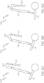
- Fig. 12A discloses another example of a landing gear assembly 102 in which the landing gear assembly 102 is in an extended condition and the weight of the aircraft 2400 is on the wheels.
- Fig. 12B shows a functional diagram of the landing gear assembly 102 of Fig. 12A in which the landing gear assembly 102 is in a kneeled condition and the weight of the aircraft 2400 is on the wheels.
- Fig. 12C shows a functional diagram of the landing gear assembly 102 of Fig. 12A in which the landing gear assembly 102 is in a retracted condition and the aircraft 2400 is in flight.
- Fig. 24 shows an aircraft 2400 that incorporates one or more examples of retract actuator assemblies 100 disclosed herein.
- a retract actuator assembly 100 for a landing gear assembly 102 of an aircraft 2400 includes a retract actuator 104 and a kneel stop assembly 106.
- the retract actuator 104 includes an actuator housing 202 and a piston 212.
- the actuator housing 202 defines a longitudinal axis 204 extending through a distal end 206 and a proximal end 208.
- the actuator housing 202 includes a cylinder bore 210 along the longitudinal axis 204.
- the piston 212 disposed within the cylinder bore 210 and configured to move within the cylinder bore 210 along the longitudinal axis 204.
- the cylinder bore 210 defines a piston stroke 214 within the actuator housing 202 that defines limits for movement of the piston 212.
- the piston stroke 214 includes an extended piston position 216 relating to the distal end 206 of the actuator housing 202 and a retracted piston position 218 relating to the proximal end 208 of the actuator housing 202.
- the kneel stop assembly 106 secured to an exterior surface 220 of the actuator housing 202 in relation to the extended piston position 216 within the cylinder bore 210 and the retracted piston position 218 within the cylinder bore 210.
- the kneel stop assembly 106 configured to selectively establish a kneel stop position 302 within the cylinder bore 210 to reduce the piston stroke 214 by inhibiting movement of the piston 212 to the retracted piston position 218.
- the retract actuator assembly 100 also includes a shock absorber 108 secured to the proximal end 208 of the actuator housing 202 such that the shock absorber 108 and retract actuator 104 are aligned along the longitudinal axis 204 of the actuator housing 202 to form an inline shock absorber actuator 110.
- the shock absorber 108 is configured to pivotally attach to a trailing arm 112 of the landing gear assembly 102.
- the piston 212 defines a rod chamber 222 in the cylinder bore 210 relating to the distal end 206 of the actuator housing 202 and a piston chamber 224 in the cylinder bore 210 relating to the proximal end 208 of the actuator housing 202.
- the retract actuator 104 also includes a piston rod 226 disposed within the rod chamber 222.
- the piston rod 226 includes a first end 228 attached to the piston 212 and a second end 230 extending through a sealed aperture 232 at the distal end 206 of the actuator housing 202.
- the retract actuator assembly 100 also includes a shock absorber 108 secured to the proximal end 208 of the actuator housing 202 such that the shock absorber 108 and retract actuator 104 are aligned along the longitudinal axis 204 of the actuator housing 202 to form an inline shock absorber actuator 110.
- the shock absorber 108 is configured to pivotally attach to a trailing arm 112 of the landing gear assembly 102.
- a mechanical linkage for the landing gear assembly 102 comprises a trailing arm 112 of the landing gear assembly 102 and the inline shock absorber actuator 110.
- the proximal end 208 of the actuator housing 202 is configured to pivotally attach to a fixed point on the aircraft 2400.
- the retract actuator assembly 100 also includes a shock absorber 108 mechanically linked to the second end 230 of the piston rod 226.
- the shock absorber 108 is configured to pivotally attach to a trailing arm 112 of the landing gear assembly 102.
- a mechanical linkage for the landing gear assembly 102 includes a trailing arm 112 of the landing gear assembly 102, the shock absorber 108, the retract actuator 104 and a linking member 1202 between the retract actuator 104 and the shock absorber 108.
- the retract actuator 104 also includes a rod hydraulic port 234 and a piston hydraulic port 236.
- the rod hydraulic port 234 disposed proximate the distal end 206 of the actuator housing 202 to provide fluidic access to the rod chamber 222.
- the piston hydraulic port 236 disposed proximate the proximal end 208 of the actuator housing 202 to provide fluidic access to the piston chamber 224.
- the extended piston position 216 of the piston stroke 214 within the cylinder bore 210 relates to a fully extended condition 1002 of the landing gear assembly 102 in conjunction with a landing sequence of the aircraft 2400.
- the retracted piston position 218 of the piston stroke 214 within the cylinder bore 210 relates to a fully retracted condition 802 of the landing gear assembly 102 in conjunction with a takeoff sequence of the aircraft 2400.
- the kneel stop position 302 of the piston stroke 214 within the cylinder bore 210 relates to a kneeling condition 602 of the landing gear assembly 102 during ground operations of the aircraft 2400.
- the kneel stop assembly 106 is configured to permit the piston 212 to move from the kneel stop position 302 to the extended piston position 216 of the piston stroke 214 within the cylinder bore 210. In still other examples of the retract actuator assembly 100, the kneel stop assembly 106 is configured to selectively remove the kneel stop position 302 of the piston stroke 214 within the cylinder bore 210 to permit movement of the piston 212 to the retracted piston position 218 of the piston stroke 214.
- the kneel stop assembly 106 includes a kneel stop housing 1102, a kneel stop insert port 308 and a kneel stop withdraw port 312.
- the a kneel stop housing 1102 secured to the exterior surface 220 of the actuator housing 202 of the retract actuator 104 in relation to the extended piston position 216 within the cylinder bore 210 of the retract actuator 104 and the retracted piston position 218 within the cylinder bore 210.
- the kneel stop housing 1102 includes a kneel stop distal end 1104 closer to the distal end 206 of the actuator housing 202 and a kneel stop proximal end 1106 closer to the proximal end 208 of the actuator housing 202.
- the kneel stop housing 1102 defines a cavity 304 between an interior surface 306 of the kneel stop housing 1102 and the exterior surface 220 of the actuator housing 202.
- the kneel stop insert port 308 disposed on the kneel stop housing 1102 to provide fluidic access to a kneel stop insert chamber 310 formed within the cavity 304.
- the kneel stop withdraw port 312 disposed on the kneel stop housing 1102 to provide fluidic access to a kneel stop withdraw chamber 314 formed within the cavity 304.
- the kneel stop insert port 308 is configured to receive a pressurized fluid from a pressurized fluid source and the kneel stop assembly 106 is configured to establish the kneel stop position 302 in response to receipt of the pressurized fluid at the kneel stop insert port 308.
- the pressurized fluid includes a pressurized hydraulic fluid, a pressurized oil, a compressed gas, a compressed air or any other suitable pressurized fluid in any suitable combination.
- the kneel stop insert port 308 is configured to permit the pressurized fluid to exit the kneel stop assembly 106 after the pressurized fluid is no longer applied by the pressurized fluid source.
- the kneel stop assembly 106 is configured such that exiting of the pressurized fluid via the kneel stop insert port 308 does not impact a current state of the kneel stop position 302.
- the kneel stop withdraw port 312 is configured to receive a pressurized fluid from a pressurized fluid source. In these and certain other examples, the kneel stop assembly 106 is configured to remove the kneel stop position 302 in response to receipt of the pressurized fluid at the kneel stop withdraw port 312. In even further examples, the kneel stop withdraw port 312 is configured to permit the pressurized fluid to exit the kneel stop assembly 106. In these and certain other examples, the kneel stop assembly 106 is configured such that exiting of the pressurized fluid via the kneel withdraw port 312 does not impact a current state of the kneel stop position 302.
- the kneel stop assembly 106 also includes at least one kneel stop segment 1108 disposed within the cavity 304 of the kneel stop housing 1102 at a predetermined point 1109 along the longitudinal axis 204 of the actuator housing 202.
- the actuator housing 202 includes at least one kneel stop aperture 1110 extending through the actuator housing 202 to the cylinder bore 210.
- the at least one kneel stop aperture 1110 configured to receive at least a portion of the at least one kneel stop segment 1108.
- the at least one kneel stop segment 1108 configured for selective insertion into the at least one kneel stop aperture 1110 and configured for selective removal from the at least one kneel stop aperture 1110.
- the at least one kneel stop segment 1108 includes at least two kneel stop segments 1108 radially dispersed around the actuator housing 202 at the predetermined point 1109.
- the at least one kneel stop aperture 1110 comprises at least two kneel stop apertures 1110 radially dispersed around the actuator housing 202 in relation to the at least two kneel stop segments 1108.
- the at least one kneel stop segment 1108 of the kneel stop assembly 106 includes two kneel stop segments, three kneel stop segments, four kneel stop segments, five kneel stop segments, six kneel stop segments or any other suitable quantity of kneel stop segments.
- the at least one kneel stop aperture 1110 of the retract actuator 104 includes two kneel stop apertures, three kneel stop apertures, four kneel stop apertures, five kneel stop apertures, six kneel stop apertures or any other suitable quantity of kneel stop apertures.
- the kneel stop insert port 308 is configured to receive a pressurized fluid from a pressurized fluid source and the kneel stop assembly 106 is configured to insert the at least one kneel stop segment 1108 into the at least one kneel stop aperture 1110 of the actuator housing 202 to establish the kneel stop position 302 in response to receipt of the pressurized fluid at the kneel stop insert port 308.
- the kneel stop withdraw port 312 is configured to receive a pressurized fluid from a pressurized fluid source and the kneel stop assembly 106 is configured to withdraw the at least one kneel stop segment 1108 from the at least one kneel stop aperture 1110 of the actuator housing 202 to remove the kneel stop position 302 in response to receipt of the pressurized fluid at the kneel stop withdraw port 312.
- the kneel stop assembly 106 also includes an upper biasing member 1112, an upper slider member 1114, a lower biasing member 1118 and a lower slider member 1120.
- the an upper biasing member 1112 disposed within the cavity 304 between the kneel stop housing 1102 and the actuator housing 202 and proximate the kneel stop distal end 1104 of the kneel stop housing 1102.
- the upper slider member 1114 disposed within the cavity 304 between the kneel stop housing 1102 and the actuator housing 202 and between the upper biasing member 1112 and the at least one kneel stop segment 1108.
- the upper slider member 1114 includes a first portion of an upper slider exterior surface 1116 facing the interior surface 306 of the kneel stop housing 1102.
- the first portion of the upper slider exterior surface 1116 and an opposing portion of the interior surface 306 for the kneel stop housing 1102 are configured to form the kneel stop insert chamber 310.
- the upper biasing member 1112 configured to bias the upper slider member 1114 toward the at least one kneel stop segment 1108.
- the lower biasing member 1118 disposed within the cavity 304 between the kneel stop housing 1102 and the actuator housing 202 and proximate the kneel stop proximal end 1106 of the kneel stop housing 1102.
- the lower slider member 1120 disposed within the cavity 304 between the kneel stop housing 1102 and the actuator housing 202 and between the at least one kneel stop segment 1108 and the lower biasing member 1118.
- the lower slider member 1120 includes a first portion of a lower slider exterior surface 1122 facing the interior surface 306 of the kneel stop housing 1102.
- the first portion of the lower slider exterior surface 1122 and an opposing portion of the interior surface 306 for the kneel stop housing 1102 are configured to form the kneel stop withdraw chamber 314.
- the lower biasing member 1118 configured to bias the lower slider member 1120 toward the at least one kneel stop segment 1108.
- the upper slider member 1114 of the kneel stop assembly 106 also includes a second portion of the upper slider exterior surface 1116 in opposing geometric relation with an upper surface of the at least one kneel stop segment 1108 and a third portion of the upper slider exterior surface 1116 adjacent to a corresponding portion of the exterior surface 220 of the actuator housing 202.
- the second portion of the upper slider exterior surface 1116 rises at a predetermined angle from the third portion of the upper slider exterior surface 1116 to the first portion of the upper slider exterior surface 1116 to facilitate withdrawing the at least one kneel stop segment 1108 from the at least one kneel stop aperture 1110 of the actuator housing 202.
- the first portion of the upper slider exterior surface 1116 and the third portion of the upper slider exterior surface 1116 are configured to slide between the at least one kneel stop segment 1108 and the exterior surface 220 of the actuator housing 202 in response to application of pressure at the kneel stop withdraw port 312 to block the at least one kneel stop segment 1108 from being inserted into the at least one kneel stop aperture 1110.
- the lower slider member 1120 of the kneel stop assembly 106 also includes a second portion of the lower slider exterior surface 1122 in opposing geometric relation with a lower surface of the at least one kneel stop segment 1108 and a third portion of the lower slider exterior surface 1122 adjacent to a corresponding portion of the interior surface 306 of the kneel stop housing 1102.
- the second portion of the lower slider exterior surface 1122 falls at a predetermined angle from the first portion of the lower slider exterior surface 1122 to the third portion of the lower slider exterior surface 1122 to facilitate inserting the at least one kneel stop segment 1108 into the at least one kneel stop aperture 1110 of the actuator housing 202.
- the first portion of the lower slider exterior surface 1122 and the third portion of the lower slider exterior surface 1122 are configured to slide between the at least one kneel stop segment 1108 and the interior surface 306 of the kneel stop housing 1102 in response to application of pressure at the kneel stop insert port 308 to block the at least one kneel stop segment 1108 from being withdrawn from the at least one kneel stop aperture 1110.
- the kneel stop insert port 308 is configured to receive a pressurized fluid from a pressurized fluid source and to provide the pressurized fluid to the kneel stop insert chamber 310.
- the kneel stop assembly 106 is configured to move the upper slider member 1114 toward the upper biasing member 1112 and away from the at least one kneel stop segment 1108 in response to receipt of the pressurized fluid by the kneel stop insert chamber 310.
- the kneel stop assembly 106 is configured to move the lower slider member 1120 toward the at least one kneel stop segment 1108 in response to the upper slider member 1114 moving away from the at least one kneel stop segment 1108 and the lower biasing member 1118 biasing the lower slider member 1120 toward the at least one kneel stop segment 1108.
- the kneel stop assembly 106 is configured to insert the at least one kneel stop segment 1108 into the at least one kneel stop aperture 1110 of the actuator housing 202 in response to the lower slider member 1120 moving toward the at least one kneel stop segment 1108 and pushing the at least one kneel stop segment 1108 into the at least one kneel stop aperture 1110 to establish the kneel stop position 302 within the cylinder bore 210 of the retract actuator 104.
- the lower biasing member 1118, the lower slider member 1120 and the at least one kneel stop segment 1108 are configured such that the lower slider member 1120 is moved into a locking position that maintains the at least one kneel stop segment 1108 inserted into the at least one kneel stop aperture 1110 with or without pressure applied to the kneel stop insert port 308 until pressure is applied to the kneel stop withdraw port 312.
- the kneel stop withdraw port 312 is configured to receive a pressurized fluid from a pressurized fluid source and to provide the pressurized fluid to the kneel stop withdraw chamber 314.
- the kneel stop assembly 106 is configured to move the lower slider member 1120 toward the lower biasing member 1118 and away from the at least one kneel stop segment 1108 in response to receipt of the pressurized fluid by the kneel stop withdraw chamber 314.
- the kneel stop assembly 106 is configured to move the upper slider member 1114 toward the at least one kneel stop segment 1108 in response to the lower slider member 1120 moving away from the at least one kneel stop segment 1108 and the upper biasing member 1112 biasing the upper slider member 1114 toward the at least one kneel stop segment 1108.
- the kneel stop assembly 106 is configured to withdraw the at least one kneel stop segment 1108 from the at least one kneel stop aperture 1110 of the actuator housing 202 in response to the upper slider member 1114 moving toward the at least one kneel stop segment 1108 and pushing the at least one kneel stop segment 1108 away from the at least one kneel stop aperture 1110 to remove the kneel stop position 302 from the cylinder bore 210 of the retract actuator 104.
- the retract actuator assembly 100 after the at least one kneel stop segment 1108 of the kneel stop assembly 106 is withdrawn from the at least one kneel stop aperture 1110 of the actuator housing 202.
- the upper biasing member 1112, the upper slider member 1114 and the at least one kneel stop segment 1108 are configured such that the upper slider member 1114 is moved into a locking position that maintains the at least one kneel stop segment 1108 withdrawn from the at least one kneel stop aperture 1110 with or without pressure applied to the kneel stop withdraw port 312 until pressure is applied to the kneel stop insert port 308.
- Fig. 1 discloses an example of the landing gear assembly 102 with a retract actuator assembly 100.
- Fig. 2 shows a cross-sectional view of an example of a retract actuator 104 for the retract actuator assembly 100 of Fig. 1 .
- Fig. 3 shows a cross-sectional view of an example of a kneel stop assembly 106 for the landing gear assembly 102 of Fig. 1 in which kneel stop segments 1108 are inserted into the retract actuator 104 and the retract actuator 104 is in an extended position.
- Fig. 1 discloses an example of the landing gear assembly 102 with a retract actuator assembly 100.
- Fig. 2 shows a cross-sectional view of an example of a retract actuator 104 for the retract actuator assembly 100 of Fig. 1 .
- Fig. 3 shows a cross-sectional view of an example of a kneel stop assembly 106 for the landing gear assembly 102 of Fig. 1 in which kneel stop segments 1108 are inserted into the retract actuator 104 and the retract actuator 104 is in an extended
- FIG. 4 shows a functional diagram of the landing gear assembly 102 of Fig. 1 in which the landing gear assembly 102 is in an extended condition and the weight of the aircraft 2400 is on the wheels.
- Fig. 5 shows a cross-sectional view of an example of a kneel stop assembly 106 for the landing gear assembly 102 of Fig. 1 in which the kneel stop segments 1108 are inserted into the retract actuator 104 and the retract actuator 104 is in a kneeled position.
- Fig. 6 shows a functional diagram of the landing gear assembly 102 of Fig. 1 in which the landing gear assembly 102 is in a kneeled condition and the weight of the aircraft 2400 is on the wheels.
- Fig. 7 shows a cross-sectional view of an example of a kneel stop assembly 106 for the landing gear assembly 102 of Fig. 1 in which the kneel stop segments 1108 are withdrawn from the retract actuator 104 and the retract actuator 104 is in a retracted position.
- Fig. 8 shows a functional diagram of the landing gear assembly 102 of Fig. 1 in which the landing gear assembly 102 is in a retracted condition and the aircraft 2400 is in flight.
- Fig. 7 shows a cross-sectional view of an example of a kneel stop assembly 106 for the landing gear assembly 102 of Fig. 1 in which the kneel stop segments 1108 are withdrawn from the retract actuator 104 and the retract actuator 104 is in a retracted position.
- Fig. 8 shows a functional diagram of the landing gear
- FIG. 9 shows a cross-sectional view of an example of a kneel stop assembly 106 for the landing gear assembly 102 of Fig. 1 in which the kneel stop segments 1108 are withdrawn from the retract actuator 104 and the retract actuator 104 is in an extended position.
- Fig. 10 shows a functional diagram of the landing gear assembly 102 of Fig. 1 in which the landing gear assembly 102 is in an extended condition and the aircraft 2400 is in flight.
- Fig. 11 provides an exploded view of an example of the kneel stop assembly 106 of Fig. 3 in relation to an example of a retract actuator 104 for the retract actuator assembly 100 of Fig. 1 .
- Fig. 12A discloses another example of a landing gear assembly 102 in which the landing gear assembly 102 is in an extended condition and the weight of the aircraft 2400 is on the wheels.
- Fig. 12B shows a functional diagram of the landing gear assembly 102 of Fig. 12A in which the landing gear assembly 102 is in a kneeled condition and the weight of the aircraft 2400 is on the wheels.
- Fig. 12C shows a functional diagram of the landing gear assembly 102 of Fig. 12A in which the landing gear assembly 102 is in a retracted condition and the aircraft 2400 is in flight.
- Fig. 24 shows an aircraft 2400 that incorporates one or more examples of landing gear assemblies 102 disclosed herein.
- a landing gear assembly 102 for an aircraft 2400 includes a retract actuator 104, a kneel stop assembly 106, a trailing arm 112 and a shock absorber 108.
- the retract actuator 104 includes an actuator housing 202 and a piston 212.
- the actuator housing 202 defines a longitudinal axis 204 extending through a distal end 206 and a proximal end 208.
- the actuator housing 202 includes a cylinder bore 210 along the longitudinal axis 204.
- the piston 212 disposed within the cylinder bore 210.
- the piston configured to move within the cylinder bore 210 along the longitudinal axis 204.
- the cylinder bore 210 defines a piston stroke 214 within the actuator housing 202 that defines limits for movement of the piston 212.
- the piston stroke 214 includes an extended piston position 216 relating to the distal end 206 of the actuator housing 202 and a retracted piston position 218 relating to the proximal end 208 of the actuator housing 202.
- the kneel stop assembly 106 secured to an exterior surface 220 of the actuator housing 202 in relation to the extended piston position 216 within the cylinder bore 210 and the retracted piston position 218 within the cylinder bore 210.
- the kneel stop assembly 106 configured to selectively establish a kneel stop position 302 within the cylinder bore 210 to reduce the piston stroke 214 by inhibiting movement of the piston 212 to the retracted piston position 218.
- the trailing arm 112 includes an arm proximal end 114 and an arm distal end 116, the arm distal end 116 configured to pivotally attach to a fixed point on the aircraft 2400.
- the arm proximal end 114 configured to attach to a surface contact assembly 118.
- the shock absorber 108 mechanically linked to the retract actuator 104 and configured to pivotally attach to the trailing arm 112.
- the shock absorber 108 is secured to the proximal end 208 of the actuator housing 202 such that the shock absorber 108 and retract actuator 104 are aligned along the longitudinal axis 204 of the actuator housing 202 to form an inline shock absorber actuator 110.
- the piston 212 defines a rod chamber 222 in the cylinder bore 210 relating to the distal end 206 of the actuator housing 202 and a piston chamber 224 in the cylinder bore 210 relating to the proximal end 208 of the actuator housing 202.
- the retract actuator 104 also includes a piston rod 226 disposed within the rod chamber 222.
- the piston rod 226 includes a first end 228 attached to the piston 212 and a second end 230 extending through a sealed aperture 232 at the distal end 206 of the actuator housing 202.
- the second end 230 of the piston rod 226 is configured to pivotally attach to a second fixed point on the aircraft 2400.
- the shock absorber 108 is secured to the proximal end 208 of the actuator housing 202 such that the shock absorber 108 and retract actuator 104 are aligned along the longitudinal axis 204 of the actuator housing 202 to form an inline shock absorber actuator 110.
- a mechanical linkage for the landing gear assembly 102 includes the trailing arm 112 and the inline shock absorber actuator 110.
- the second end 230 of the piston rod 226 in the retract actuator 104 is mechanically linked to the shock absorber 108 and the proximal end 208 of the actuator housing 202 is configured to pivotally attach to a second fixed point on the aircraft 2400.
- a mechanical linkage for the landing gear assembly 102 includes the trailing arm 112, the shock absorber 108, the retract actuator 104 and a linking member 1202 between the retract actuator 104 and the shock absorber 108.
- the retract actuator 104 also includes a rod hydraulic port 234 and a piston hydraulic port 236.
- the rod hydraulic port 234 disposed proximate the distal end 206 of the actuator housing 202 to provide fluidic access to the rod chamber 222.
- the piston hydraulic port 236 disposed proximate the proximal end 208 of the actuator housing 202 to provide fluidic access to the piston chamber 224.
- the surface contact assembly 118 includes a wheel, a ski or any other suitable surface contact assembly.
- the extended piston position 216 of the piston stroke 214 within the cylinder bore 210 relates to a fully extended condition 1002 of the landing gear assembly 102 in conjunction with a landing sequence of the aircraft 2400.
- the retracted piston position 218 of the piston stroke 214 within the cylinder bore 210 relates to a fully retracted condition 802 of the landing gear assembly 102 in conjunction with a takeoff sequence of the aircraft 2400.
- the kneel stop position 302 of the piston stroke 214 within the cylinder bore 210 relates to a kneeling condition 602 of the landing gear assembly 102 during ground operations of the aircraft 2400.
- the kneel stop assembly 106 is configured to permit the piston 212 to move from the kneel stop position 302 to the extended piston position 216 of the piston stroke 214 within the cylinder bore 210.
- the kneel stop assembly 106 is configured to selectively remove the kneel stop position 302 of the piston stroke 214 within the cylinder bore 210 to permit movement of the piston 212 to the retracted piston position 218 of the piston stroke 214.
- the kneel stop assembly 106 includes a kneel stop housing 1102, a kneel stop insert port 308 and a kneel stop withdraw port 312.
- the kneel stop housing 1102 secured to the exterior surface 220 of the actuator housing 202 of the retract actuator 104 in relation to the extended piston position 216 within the cylinder bore 210 of the retract actuator 104 and the retracted piston position 218 within the cylinder bore 210.
- the kneel stop housing 1102 includes a kneel stop distal end 1104 closer to the distal end 206 of the actuator housing 202 and a kneel stop proximal end 1106 closer to the proximal end 208 of the actuator housing 202.
- the kneel stop housing 1102 defines a cavity 304 between an interior surface 306 of the kneel stop housing 1102 and the exterior surface 220 of the actuator housing 202.
- the kneel stop insert port 308 disposed on the kneel stop housing 1102 to provide fluidic access to a kneel stop insert chamber 310 formed within the cavity 304.
- the kneel stop withdraw port 312 disposed on the kneel stop housing 1102 to provide fluidic access to a kneel stop withdraw chamber 314 formed within the cavity 304.
- the kneel stop assembly 106 also includes at least one kneel stop segment 1108 disposed within the cavity 304 of the kneel stop housing 1102 at a predetermined point 1109 along the longitudinal axis 204 of the actuator housing 202.
- the actuator housing 202 includes at least one kneel stop aperture 1110 extending through the actuator housing 202 to the cylinder bore 210.
- the at least one kneel stop aperture 1110 configured to receive at least a portion of the at least one kneel stop segment 1108.
- the at least one kneel stop segment 1108 configured for selective insertion into the at least one kneel stop aperture 1110 and configured for selective removal from the at least one kneel stop aperture 1110.
- the at least one kneel stop segment 1108 includes at least two kneel stop segments 1108 radially dispersed around the actuator housing 202 at the predetermined point 1109.
- the at least one kneel stop aperture 1110 includes at least two kneel stop apertures 1110 radially dispersed around the actuator housing 202 in relation to the at least two kneel stop segments 1108.
- the kneel stop assembly 106 also includes an upper biasing member 1112, an upper slider member 1114, a lower biasing member 1118 and a lower slider member 1120.
- the upper biasing member 1112 disposed within the cavity 304 between the kneel stop housing 1102 and the actuator housing 202 and proximate the kneel stop distal end 1104 of the kneel stop housing 1102.
- the upper slider member 1114 disposed within the cavity 304 between the kneel stop housing 1102 and the actuator housing 202 and between the upper biasing member 1112 and the at least one kneel stop segment 1108.
- the upper slider member 1114 includes a first portion of an upper slider exterior surface 1116 facing the interior surface 306 of the kneel stop housing 1102.
- the first portion of the upper slider exterior surface 1116 and an opposing portion of the interior surface 306 for the kneel stop housing 1102 are configured to form the kneel stop insert chamber 310.
- the upper biasing member 1112 configured to bias the upper slider member 1114 toward the at least one kneel stop segment 1108.
- the lower biasing member 1118 disposed within the cavity 304 between the kneel stop housing 1102 and the actuator housing 202 and proximate the kneel stop proximal end 1106 of the kneel stop housing 1102.
- the lower slider member 1120 disposed within the cavity 304 between the kneel stop housing 1102 and the actuator housing 202 and between the at least one kneel stop segment 1108 and the lower biasing member 1118.
- the lower slider member 1120 includes a first portion of a lower slider exterior surface 1122 facing the interior surface 306 of the kneel stop housing 1102.
- the first portion of the lower slider exterior surface 1122 and an opposing portion of the interior surface 306 for the kneel stop housing 1102 are configured to form the kneel stop withdraw chamber 314.
- the lower biasing member 1118 configured to bias the lower slider member 1120 toward the at least one kneel stop segment 1108.
- Fig. 1 discloses an example of a retract actuator assembly 100 for an example of the landing gear assembly 102.
- Fig. 2 shows a cross-sectional view of an example of a retract actuator 104 for the retract actuator assembly 100 of Fig. 1 .
- Fig. 3 shows a cross-sectional view of an example of a kneel stop assembly 106 for the retract actuator assembly 100 of Fig.
- FIG. 4 shows a functional diagram of the landing gear assembly 102 of Fig. 1 in which the landing gear assembly 102 is in an extended condition and the weight of the aircraft 2400 is on the wheels.
- Fig. 5 shows a cross-sectional view of an example of a kneel stop assembly 106 for the retract actuator assembly 100 of Fig. 1 in which the kneel stop segments 1108 are inserted into the retract actuator 104 and the retract actuator 104 is in a kneeled position.
- Fig. 6 shows a functional diagram of the landing gear assembly 102 of Fig. 1 in which the landing gear assembly 102 is in a kneeled condition and the weight of the aircraft 2400 is on the wheels.
- Fig. 7 shows a cross-sectional view of an example of a kneel stop assembly 106 for the retract actuator assembly 100 of Fig. 1 in which the kneel stop segments 1108 are withdrawn from the retract actuator 104 and the retract actuator 104 is in a retracted position.
- Fig. 8 shows a functional diagram of the landing gear assembly 102 of Fig. 1 in which the landing gear assembly 102 is in a retracted condition and the aircraft 2400 is in flight.
- Fig. 7 shows a cross-sectional view of an example of a kneel stop assembly 106 for the retract actuator assembly 100 of Fig. 1 in which the kneel stop segments 1108 are withdrawn from the retract actuator 104 and the retract actuator 104 is in a retracted position.
- Fig. 8 shows a functional diagram of the landing gear assembly
- FIG. 9 shows a cross-sectional view of an example of a kneel stop assembly 106 for the retract actuator assembly 100 of Fig. 1 in which the kneel stop segments 1108 are withdrawn from the retract actuator 104 and the retract actuator 104 is in an extended position.
- Fig. 10 shows a functional diagram of the landing gear assembly 102 of Fig. 1 in which the landing gear assembly 102 is in an extended condition and the aircraft 2400 is in flight.
- Fig. 11 provides an exploded view of an example of the kneel stop assembly 106 of Fig. 3 in relation to an example of a retract actuator 104 for the retract actuator assembly 100 of Fig. 1 .
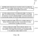
- Fig. 13 discloses an example of the method 1300 for kneeling a landing gear assembly 102 of an aircraft 2400.
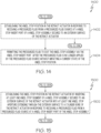
- Fig. 14 in combination with Fig. 13 , discloses an example of the method 1400 for kneeling a landing gear assembly 102 of an aircraft 2400.
- Fig. 15 in combination with Fig. 13 , discloses an example of the method 1500 for kneeling a landing gear assembly 102 of an aircraft 2400.
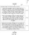
- Fig. 16 in combination with Fig. 13 , discloses an example of the method 1600 for kneeling a landing gear assembly 102 of an aircraft 2400.
- Fig. 17 in combination with Figs. 13 and 16 , discloses an example of the method 1700 for kneeling a landing gear assembly 102 of an aircraft 2400.
- Fig. 18 in combination with Fig. 13 , discloses an example of the method 1800 for kneeling a landing gear assembly 102 of an aircraft 2400.
- Fig. 19 in combination with Figs. 13 and 18 , discloses an example of the method 1900 for kneeling a landing gear assembly 102 of an aircraft 2400.
- Fig. 20 in combination with Figs. 13 and 18 , discloses an example of the method 2000 for kneeling a landing gear assembly 102 of an aircraft 2400.
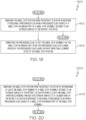
- Fig. 21 in combination with Figs. 13 and 18 , discloses an example of the method 2100 for kneeling a landing gear assembly 102 of an aircraft 2400.
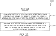
- Fig. 22 in combination with Figs.
- FIG. 13 , 18 and 21 discloses an example of the method 2200 for kneeling a landing gear assembly 102 of an aircraft 2400.
- Fig. 24 shows an aircraft 2400 that incorporates one or more examples of retract actuator assemblies 100 and landing gear assemblies 102 disclosed herein.
- a method 1300 for kneeling a landing gear assembly 102 of an aircraft 2400 includes performing 1302 ground operations for the aircraft 2400 in which the landing gear assembly 102 is in a fully extended condition 1002 and a retract actuator 104 of the landing gear assembly 102 is in an extended piston position 216.
- a kneeling feature of the landing gear assembly 102 is activated to establish a kneel stop position 302 in the retract actuator 104 that reduces a piston stroke 214 for the retract actuator 104 by inhibiting movement of a piston 212 in the retract actuator 104 beyond the kneel stop position 302 toward a retracted piston position 218.
- the landing gear assembly 102 is moved from the fully extended condition 1002 to a kneeling condition 602 by moving the retract actuator 104 from the extended piston position 216 to the kneel stop position 302.
- the extended piston position 216 of the piston stroke 214 within a cylinder bore 210 of the retract actuator 104 relates to the fully extended condition 1002 of the landing gear assembly 102 in conjunction with a landing sequence of the aircraft 2400.
- the retracted piston position 218 of the piston stroke 214 within a cylinder bore 210 of the retract actuator 104 relates to a fully retracted condition 802 of the landing gear assembly 102 in conjunction with a takeoff sequence of the aircraft 2400.
- the kneel stop position 302 of the piston stroke 214 within a cylinder bore 210 of the retract actuator 104 relates to the kneeling condition 602 of the landing gear assembly 102 during ground operations of the aircraft 2400.
- the method 1300 also includes moving 1308 the landing gear assembly 102 from the kneeling condition 602 to the fully extended condition 1002 by moving the retract actuator 104 from the kneel stop position 302 to the extended piston position 216 while the kneeling feature of the landing gear assembly 102 remains activated.
- a method 1400 for kneeling a landing gear assembly 102 of an aircraft 2400 includes the method 1300 of Fig. 13 .
- the method 1400 continues from 1304 to 1402 where the kneel stop position 302 is established in the retract actuator 104 in response to receiving a pressurized fluid from a pressurized fluid source at a kneel stop insert port 308 of a kneel stop assembly 106 secured to an exterior surface 220 of the retract actuator 104.
- the method 1400 continues from 1402 to 1306 (see Fig. 13 ).
- the method also includes permitting 1404 the pressurized fluid to exit the kneel stop assembly 106 via the kneel stop insert port 308 after the pressurized fluid is no longer applied by the pressurized fluid source without impacting a current state of the kneel stop position 302.
- a method 1500 for kneeling a landing gear assembly 102 of an aircraft 2400 includes the method 1300 of Fig. 13 .
- the method 1500 continues from 1304 to 1502 where the kneel stop position 302 is established in the retract actuator 104 by inserting at least one kneel stop segment 1108 of a kneel stop assembly 106 secured to an exterior surface 220 of the retract actuator 104 into at least one kneel stop aperture 1110 extending through the exterior surface 220 to a cylinder bore 210 of the retract actuator 104 in response to receiving a pressurized fluid from a pressurized fluid source at a kneel stop insert port 308 of the kneel stop assembly 106.
- the method 1500 continues from 1502 to 1306 (see Fig. 13 ).
- a method 1600 for kneeling a landing gear assembly 102 of an aircraft 2400 includes the method 1300 of Fig. 13 .
- the method 1600 continues from 1304 to 1602 where the kneel stop position 302 is established in the retract actuator 104.
- the establishing 1602 includes moving an upper slider member 1114 of a kneel stop assembly 106 secured to an exterior surface 220 of the retract actuator 104 toward an upper biasing member 1112 of the kneel stop assembly 106 and away from at least one kneel stop segment 1108 of the kneel stop assembly 106 in response to receiving a pressurized fluid from a pressurized fluid source at a kneel stop insert chamber 310 of the kneel stop assembly 106 via a kneel stop insert port 308 of the kneel stop assembly 106.
- the at least one kneel stop segment 1108 is no longer locked and is free to move laterally between the interior surface 306 of the kneel stop housing 1102 and the exterior surface 220 of the actuator housing 202 after the upper slider member 1114 moves toward the upper biasing member 1112.
- the establishing 1602 also includes moving a lower slider member 1120 of the kneel stop assembly 106 toward the at least one kneel stop segment 1108 in response to the upper slider member 1114 moving away from the at least one kneel stop segment 1108, the at least one kneel stop segment 1108 being free to move laterally and a lower biasing member 1118 biasing the lower slider member 1120 toward the at least one kneel stop segment 1108.
- the establishing 1602 also includes inserting the at least one kneel stop segment 1108 into at least one kneel stop aperture 1110 extending through the exterior surface 220 to a cylinder bore 210 of the retract actuator 104 in response to the lower slider member 1120 moving toward the at least one kneel stop segment 1108 and opposing tapered surfaces of the lower slider member 1120 pushing the at least one kneel stop segment 1108 into the at least one kneel stop aperture 1110 to establish the kneel stop position 302 within the cylinder bore 210 of the retract actuator 104.
- the method 1600 continues from 1602 to 1306 (see Fig. 13 ).
- a method 1700 for kneeling a landing gear assembly 102 of an aircraft 2400 includes the methods 1300, 1600 of Figs. 13 and 16 .
- the method 1700 continues from 1608 to 1702 where the kneel stop position 302 in the retract actuator 104 is locked after the at least one kneel stop segment 1108 of the kneel stop assembly 106 is inserted into the at least one kneel stop aperture 1110 of an actuator housing 202.
- the at least one kneel stop segment 1108 inserted into the at least one kneel stop aperture 1110 is maintained with or without pressure applied to the kneel stop insert port 308 until pressure is applied to a kneel stop withdraw port 312 of the kneel stop assembly 106.
- a method 1800 for kneeling a landing gear assembly 102 of an aircraft 2400 includes the method 1300 of Fig. 13 .
- the method 1800 continues from 1306 to 1802 where the kneeling feature of the landing gear assembly 102 is deactivated to remove the kneel stop position 302 from the retract actuator 104 to permit movement of the piston 212 to the retracted piston position 218 of the piston stroke 214.
- a takeoff sequence for the aircraft 2400 is started in which the landing gear assembly 102 is in the fully extended condition 1002 and the retract actuator 104 of the landing gear assembly 102 is in the extended piston position 216.
- the takeoff sequence is completed and flight operations for the aircraft 2400 are performed in which the landing gear assembly 102 is in a fully retracted condition 802 and the retract actuator 104 is in the retracted piston position 218.
- a method 1900 for kneeling a landing gear assembly 102 of an aircraft 2400 includes the methods 1300, 1800 of Figs. 13 and 18 .
- the method 1900 continues from 1802 to 1902 where the kneel stop position 302 is removed from the retract actuator 104 in response to receiving a pressurized fluid from a pressurized fluid source at a kneel stop withdraw port 312 of a kneel stop assembly 106 secured to an exterior surface 220 of the retract actuator 104.
- the method 1900 continues from 1902 to 1804 (see Fig. 18 ).
- the method 1900 also includes permitting 1904 the pressurized fluid to exit the kneel stop assembly 106 via the kneel stop withdraw port 312 after the pressurized fluid is no longer applied by the pressurized fluid source without impacting a current state of the kneel stop position 302.
- a method 2000 for kneeling a landing gear assembly 102 of an aircraft 2400 includes the methods 1300, 1800 of Figs. 13 and 18 .
- the method 2000 continues from 1802 to 2002 where the kneel stop position 302 is removed from the retract actuator 104 by withdrawing at least one kneel stop segment 1108 of a kneel stop assembly 106 secured to an exterior surface 220 of the retract actuator 104 from at least one kneel stop aperture 1110 extending through the exterior surface 220 to a cylinder bore 210 of the retract actuator 104 in response to receiving a pressurized fluid from a pressurized fluid source at a kneel stop withdraw port 312 of the kneel stop assembly 106.
- the method 2000 continues from 2002 to 1804 (see Fig. 18 ).
- a method 2100 for kneeling a landing gear assembly 102 of an aircraft 2400 includes the methods 1300, 1800 of Figs. 13 and 18 .
- the method 2100 continues from 1802 to 2102 where the kneel stop position 302 is removed from the retract actuator 104.
- the removing 2102 includes moving a lower slider member 1120 of a kneel stop assembly 106 secured to an exterior surface 220 of the retract actuator 104 toward a lower biasing member 1118 of the kneel stop assembly 106 and away from at least one kneel stop segment 1108 of the kneel stop assembly 106 in response to receiving a pressurized fluid from a pressurized fluid source at a kneel stop withdraw chamber 314 of the kneel stop assembly 106 via a kneel stop withdraw port 312 of the kneel stop assembly 106.
- the at least one kneel stop segment 1108 is no longer locked and free to move laterally between the interior surface 306 of the kneel stop housing 1102 and the exterior surface 220 of the actuator housing 202 after the lower slider member 1120 moves toward the lower biasing member 1118.
- the removing 2102 also includes moving an upper slider member 1114 of the kneel stop assembly 106 toward the at least one kneel stop segment 1108 in response to the lower slider member 1120 moving away from the at least one kneel stop segment 1108, the at least one kneel stop segment 1108 being free to move laterally and an upper biasing member 1112 biasing the upper slider member 1114 toward the at least one kneel stop segment 1108.
- the removing 2102 also includes withdrawing the at least one kneel stop segment 1108 from at least one kneel stop aperture 1110 extending through the exterior surface 220 to a cylinder bore 210 of the retract actuator 104 in response to the upper slider member 1114 moving toward the at least one kneel stop segment 1108 and opposing tapered surfaces of the upper slider member 1114 pushing the at least one kneel stop segment 1108 away from the at least one kneel stop aperture 1110 to remove the kneel stop position 302 from the cylinder bore 210 of the retract actuator 104.
- a method 2200 for kneeling a landing gear assembly 102 of an aircraft 2400 includes the methods 1300, 1800, 2100 of Figs. 13 , 18 and 21 .
- the method 2200 continues from 2108 to 2202 where the kneel stop position 302 in the retract actuator 104 is locked out after the at least one kneel stop segment 1108 of the kneel stop assembly 106 is withdrawn from the at least one kneel stop aperture 1110 of an actuator housing 202.
- the at least one kneel stop segment 1108 withdrawn from the at least one kneel stop aperture 1110 is maintained with or without pressure applied to the kneel stop withdraw port 312 until pressure is applied to a kneel stop insert port 308 of the kneel stop assembly 106.
- Examples of the retract actuator assembly 100, landing gear assembly 102 and methods 1300, 1400, 1500, 1600, 1700, 1800, 1900, 2000, 2100, 2200 for kneeling a landing gear assembly 102 of an aircraft 2400 may be related to or used in the context of aircraft manufacturing.
- the examples and principles disclosed herein may be applied to other products in the aerospace industry and other industries, such as the automotive industry, the space industry, the construction industry and other design and manufacturing industries. Accordingly, in addition to aircraft, the examples and principles disclosed herein may apply to the use of kneeling in the manufacture and/or operation of various types of vehicles and in the construction of various types of buildings.
- example means that one or more feature, structure, element, component, characteristic and/or operational step described in connection with the example is included in at least one example, of the subject matter according to the present disclosure.
- the phrases “an example,” “another example,” “one or more examples,” and similar language throughout the present disclosure may, but do not necessarily, refer to the same example.
- the subject matter characterizing any one example may, but does not necessarily, include the subject matter characterizing any other example.
- the subject matter characterizing any one example may be, but is not necessarily, combined with the subject matter characterizing any other example.
- a system, apparatus, device, structure, article, element, component, or hardware “configured to” perform a specified function is indeed capable of performing the specified function without any alteration, rather than merely having potential to perform the specified function after further modification.
- the system, apparatus, device, structure, article, element, component, or hardware “configured to” perform a specified function is specifically selected, created, implemented, utilized, programmed and/or designed for the purpose of performing the specified function.
- "configured to” denotes existing characteristics of a system, apparatus, structure, article, element, component, or hardware that enable the system, apparatus, structure, article, element, component, or hardware to perform the specified function without further modification.
- a system, apparatus, device, structure, article, element, component, or hardware described as being “configured to” perform a particular function may additionally or alternatively be described as being “adapted to” and/or as being “operative to” perform that function.
- first,” “second,” “third,” etc. are used herein merely as labels and are not intended to impose ordinal, positional, or hierarchical requirements on the items to which these terms refer. Moreover, reference to, e.g., a “second” item does not require or preclude the existence of, e.g., a "first” or lower-numbered item and/or, e.g., a "third” or higher-numbered item.
- the phrase "at least one of,” when used with a list of items, means different combinations of one or more of the listed items may be used and only one of each item in the list may be needed.
- “at least one of item A, item B and item C” may include, without limitation, item A or item A and item B. This example also may include item A, item B and item C or item B and item C.
- "at least one of” may be, for example, without limitation, two of item A, one of item B and ten of item C; four of item B and seven of item C; and other suitable combinations.
- the term “and/or" and the "/" symbol includes any and all combinations of one or more of the associated listed items.
- Coupled refers to two or more elements that are joined, linked, fastened, attached, connected, put in communication, or otherwise associated (e.g., mechanically, electrically, fluidly, optically, electromagnetically) with one another.
- the elements may be associated directly or indirectly.
- element A may be directly associated with element B.
- element A may be indirectly associated with element B, for example, via another element C. It will be understood that not all associations among the various disclosed elements are necessarily represented. Accordingly, couplings other than those depicted in the figures may also exist.
- the term “approximately” refers to or represents a condition that is close to, but not exactly, the stated condition that still performs the desired function or achieves the desired result.
- the term “approximately” refers to a condition that is within an acceptable predetermined tolerance or accuracy, such as to a condition that is within 10% of the stated condition.
- the term “approximately” does not exclude a condition that is exactly the stated condition.
- the term “substantially” refers to a condition that is essentially the stated condition that performs the desired function or achieves the desired result.
- Figs. 1-11 , 12A-C and 24 may represent functional elements, features, or components thereof and do not necessarily imply any particular structure. Accordingly, modifications, additions and/or omissions may be made to the illustrated structure. Additionally, those skilled in the art will appreciate that not all elements, features and/or components described and illustrated in Figs. 1-11 , 12A-C and 24 , referred to above, need be included in every example and not all elements, features and/or components described herein are necessarily depicted in each illustrative example. Accordingly, some of the elements, features and/or components described and illustrated in Figs.
- Figs. 12-23 referred to above, the blocks may represent operations, steps and/or portions thereof and lines connecting the various blocks do not imply any particular order or dependency of the operations or portions thereof. It will be understood that not all dependencies among the various disclosed operations are necessarily represented. Figs. 12-23 and the accompanying disclosure describing the operations of the disclosed methods set forth herein should not be interpreted as necessarily determining a sequence in which the operations are to be performed. Rather, although one illustrative order is indicated, it is to be understood that the sequence of the operations may be modified when appropriate. Accordingly, modifications, additions and/or omissions may be made to the operations illustrated and certain operations may be performed in a different order or simultaneously. Additionally, those skilled in the art will appreciate that not all operations described need be performed.
- references throughout the present specification to features, advantages, or similar language used herein do not imply that all the features and advantages that may be realized with the examples disclosed herein should be, or are in, any single example. Rather, language referring to the features and advantages is understood to mean that a specific feature, advantage, or characteristic described in connection with an example is included in at least one example. Thus, discussion of features, advantages and similar language used throughout the present disclosure may, but does not necessarily, refer to the same example.
- the disclosed methods and systems for associating test data for a part under test with an end item coordinate system may be used in aircraft manufacturing.
- the service method 2300 may include specification and design (block 2302) of aircraft 2400 and material procurement (block 2304).
- component and subassembly manufacturing (block 2306) and system integration (block 2308) of aircraft 2400 may take place.
- aircraft 2400 may go through certification and delivery (block 2310) to be placed in service (block 2312).
- aircraft 2400 may be scheduled for routine maintenance and service (block 2314). Routine maintenance and service may include modification, reconfiguration, refurbishment, etc. of one or more systems of aircraft 2400.
- Each of the processes of the service method 2300 may be performed or carried out by a system integrator, a third party and/or an operator (e.g., a customer).
- a system integrator may include, without limitation, any number of aircraft manufacturers and major-system subcontractors;
- a third party may include, without limitation, any number of vendors, subcontractors and suppliers;
- an operator may be an airline, leasing company, military entity, service organization and so on.
- aircraft 2400 produced by the service method 2300 may include airframe 2402 with a plurality of high-level systems 2404 and interior 2406.
- high-level systems 2404 include one or more of propulsion system 2408, electrical system 2410, hydraulic system 2412 and environmental system 2414. Any number of other systems may be included.
- propulsion system 2408 one or more of propulsion system 2408, electrical system 2410, hydraulic system 2412 and environmental system 2414. Any number of other systems may be included.
- an aerospace example is shown, the principles disclosed herein may be applied to other industries, such as the automotive industry. Accordingly, in addition to aircraft 2400, the principles disclosed herein may apply to other vehicles, e.g., land vehicles, marine vehicles, space vehicles, etc.
- the disclosed systems and methods for associating test data for a part under test with an end item coordinate system may be employed during any one or more of the stages of the manufacturing and service method 2300.
- components or subassemblies corresponding to component and subassembly manufacturing (block 2306) may be fabricated or manufactured in a manner similar to components or subassemblies produced while aircraft 2400 is in service (block 2312).
- one or more examples of the system(s), method(s), or combination thereof may be utilized during production stages (block 2306 and block 2308), for example, by expediting or substantially expediting assembly of or reducing the cost of aircraft 2400.
- one or more examples of the system or method realizations, or a combination thereof may be utilized, for example and without limitation, while aircraft 2400 is in service (block 2312) and/or during maintenance and service (block 2314).
- Clause 3 The retract actuator assembly of Clause 1 or 2 wherein the piston (212) defines a rod chamber (222) in the cylinder bore (210) relating to the distal end (206) of the actuator housing (202) and a piston chamber (224) in the cylinder bore (210) relating to the proximal end (208) of the actuator housing (202), the retract actuator (104) further comprising: a piston rod (226) disposed within the rod chamber (222) and comprising a first end (228) attached to the piston (212) and a second end (230) extending through a sealed aperture (232) at the distal end (206) of the actuator housing (202).
- Clause 4 The retract actuator assembly of Clause 3 wherein the second end (230) of the piston rod (226) is configured to pivotally attach to a fixed point on the aircraft (2400), the retract actuator assembly (100) further comprising: a shock absorber (108) secured to the proximal end (208) of the actuator housing (202) such that the shock absorber (108) and retract actuator (104) are aligned along the longitudinal axis (204) of the actuator housing (202) to form an inline shock absorber actuator (110), the shock absorber (108) configured to pivotally attach to a trailing arm (112) of the landing gear assembly (102).
- a shock absorber (108) secured to the proximal end (208) of the actuator housing (202) such that the shock absorber (108) and retract actuator (104) are aligned along the longitudinal axis (204) of the actuator housing (202) to form an inline shock absorber actuator (110), the shock absorber (108) configured to pivotally attach to a trailing arm (112) of the landing gear assembly (102).
- Clause 7 The retract actuator assembly of Clause 6 wherein a mechanical linkage for the landing gear assembly (102) comprises a trailing arm (112) of the landing gear assembly (102), the shock absorber (108), the retract actuator (104) and a linking member (1202) between the retract actuator (104) and the shock absorber (108).
- Clause 8 The retract actuator assembly of an of Clauses 3 to 7, the retract actuator (104) further comprising: a rod hydraulic port (234) disposed proximate the distal end (206) of the actuator housing (202) to provide fluidic access to the rod chamber (222); and a piston hydraulic port (236) disposed proximate the proximal end (208) of the actuator housing (202) to provide fluidic access to the piston chamber (224).
- Clause 9 The retract actuator assembly of any of Clauses 1 to 8 wherein the extended piston position (216) of the piston stroke (214) within the cylinder bore (210) relates to a fully extended condition (1002) of the landing gear assembly (102) in conjunction with a landing sequence of the aircraft (2400).
- Clause 10 The retract actuator assembly of any of Clauses 1 to 9 wherein the retracted piston position (218) of the piston stroke (214) within the cylinder bore (210) relates to a fully retracted condition (802) of the landing gear assembly (102) in conjunction with a takeoff sequence of the aircraft (2400).
- the kneel stop assembly (106) comprising: a kneel stop housing (1102) secured to the exterior surface (220) of the actuator housing (202) of the retract actuator (104) in relation to the extended piston position (216) within the cylinder bore (210) of the retract actuator (104) and the retracted piston position (218) within the cylinder bore (210), the kneel stop housing (1102) comprising a kneel stop distal end (1104) closer to the distal end (206) of the actuator housing (202) and a kneel stop proximal end (1106) closer to the proximal end (208) of the actuator housing (202), the kneel stop housing (1102) defining a cavity (304) between an interior surface (306) of the kneel stop housing (1102) and the exterior surface (220) of the actuator housing (202); a kneel stop insert port (308) disposed on the kneel stop housing (1102) to provide fluidic access to a kneel stop insert chamber (310) formed within the cavity (304); and a kneel stop withdraw
- Clause 15 The retract actuator assembly of Clause 14 wherein the kneel stop insert port (308) is configured to receive a pressurized fluid from a pressurized fluid source and the kneel stop assembly (106) is configured to establish the kneel stop position (302) in response to receipt of the pressurized fluid at the kneel stop insert port (308).
- Clause 16 The retract actuator assembly of Clause 15 wherein the pressurized fluid comprises at least one of a pressurized hydraulic fluid, a pressurized oil, a compressed gas and a compressed air.
- Clause 17 The retract actuator assembly of Clause 15 or 16 wherein the kneel stop insert port (308) is configured to permit the pressurized fluid to exit the kneel stop assembly (106) after the pressurized fluid is no longer applied by the pressurized fluid source and the kneel stop assembly (106) is configured such that exiting of the pressurized fluid via the kneel stop insert port (308) does not impact a current state of the kneel stop position (302).
- Clause 18 The retract actuator assembly of any of Clauses 14 to 17 wherein the kneel stop withdraw port (312) is configured to receive a pressurized fluid from a pressurized fluid source and the kneel stop assembly (106) is configured to remove the kneel stop position (302) in response to receipt of the pressurized fluid at the kneel stop withdraw port (312).
- the kneel stop assembly (106) further comprising: at least one kneel stop segment (1108) disposed within the cavity (304) of the kneel stop housing (1102) at a predetermined point (1109) along the longitudinal axis (204) of the actuator housing (202), the predetermined point (1109) associated with the kneel stop position (302), the actuator housing (202) comprising at least one kneel stop aperture (1110) extending through the actuator housing (202) to the cylinder bore (210), the at least one kneel stop aperture (1110) configured to receive at least a portion of the at least one kneel stop segment (1108), the at least one kneel stop segment (1108) configured for selective insertion into the at least one kneel stop aperture (1110) and configured for selective removal from the at least one kneel stop aperture (1110).
- Clause 21 The retract actuator assembly of Clause 20, wherein the at least one kneel stop segment (1108) comprises at least two kneel stop segments (1108) radially dispersed around the actuator housing (202) at the predetermined point (1109), wherein the at least one kneel stop aperture (1110) comprises at least two kneel stop apertures (1110) radially dispersed around the actuator housing (202) in relation to the at least two kneel stop segments (1108).
- the retract actuator assembly of Clause 20 or 21 comprising at least one kneel stop segment (1108) of the kneel stop assembly (106) comprising at least one of two kneel stop segments, three kneel stop segments, four kneel stop segments, five kneel stop segments and six kneel stop segments, correspondingly, the at least one kneel stop aperture (1110) of the retract actuator (104) comprising at least one of two kneel stop apertures, three kneel stop apertures, four kneel stop apertures, five kneel stop apertures and six kneel stop apertures.
- Clause 23 The retract actuator assembly of any of Clauses 20 to 22 wherein the kneel stop insert port (308) is configured to receive a pressurized fluid from a pressurized fluid source and the kneel stop assembly (106) is configured to insert the at least one kneel stop segment (1108) into the at least one kneel stop aperture (1110) of the actuator housing (202) to establish the kneel stop position (302) in response to receipt of the pressurized fluid at the kneel stop insert port (308).
- Clause 24 The retract actuator assembly of any of Clauses 20 to 23 wherein the kneel stop withdraw port (312) is configured to receive a pressurized fluid from a pressurized fluid source and the kneel stop assembly (106) is configured to withdraw the at least one kneel stop segment (1108) from the at least one kneel stop aperture (1110) of the actuator housing (202) to remove the kneel stop position (302) in response to receipt of the pressurized fluid at the kneel stop withdraw port (312).
- Clause 28 The retract actuator assembly of any of Clauses 25 to 27 wherein the kneel stop insert port (308) is configured to receive a pressurized fluid from a pressurized fluid source and to provide the pressurized fluid to the kneel stop insert chamber (310), wherein the kneel stop assembly (106) is configured to move the upper slider member (1114) toward the upper biasing member (1112) and away from the at least one kneel stop segment (1108) in response to receipt of the pressurized fluid by the kneel stop insert chamber (310), wherein the kneel stop assembly (106) is configured to move the lower slider member (1120) toward the at least one kneel stop segment (1108) in response to the upper slider member (1114) moving away from the at least one kneel stop segment (1108) and the lower biasing member (1118) biasing the lower slider member (1120) toward the at least one kneel stop segment (1108), wherein the kneel stop assembly (106) is configured to insert the at least one kneel stop segment (1108) into the at least one kneel stop aperture (1110) of the actuator housing (202) in
- Clause 29 The retract actuator assembly of Clause 28 wherein, after the at least one kneel stop segment (1108) of the kneel stop assembly (106) is inserted into the at least one kneel stop aperture (1110) of the actuator housing (202), the lower biasing member (1118), the lower slider member (1120) and the at least one kneel stop segment (1108) are configured such that the lower slider member (1120) is moved into a locking position that maintains the at least one kneel stop segment (1108) inserted into the at least one kneel stop aperture (1110) with or without pressure applied to the kneel stop insert port (308) until pressure is applied to the kneel stop withdraw port (312).
- Clause 31 The retract actuator assembly of Clause 30 wherein, after the at least one kneel stop segment (1108) of the kneel stop assembly (106) is withdrawn from the at least one kneel stop aperture (1110) of the actuator housing (202), the upper biasing member (1112), the upper slider member (1114) and the at least one kneel stop segment (1108) are configured such that the upper slider member (1114) is moved into a locking position that maintains the at least one kneel stop segment (1108) withdrawn from the at least one kneel stop aperture (1110) with or without pressure applied to the kneel stop withdraw port (312) until pressure is applied to the kneel stop insert port (308).
- Clause 34 The landing gear assembly of Clause 32 or 33 wherein the piston (212) defines a rod chamber (222) in the cylinder bore (210) relating to the distal end (206) of the actuator housing (202) and a piston chamber (224) in the cylinder bore (210) relating to the proximal end (208) of the actuator housing (202), the retract actuator (104) further comprising: a piston rod (226) disposed within the rod chamber (222) and comprising a first end (228) attached to the piston (212) and a second end (230) extending through a sealed aperture (232) at the distal end (206) of the actuator housing (202).
- Clause 35 The landing gear assembly of Clause 34 wherein the second end (230) of the piston rod (226) is configured to pivotally attach to a second fixed point on the aircraft (2400) and the shock absorber (108) is secured to the proximal end (208) of the actuator housing (202) such that the shock absorber (108) and retract actuator (104) are aligned along the longitudinal axis (204) of the actuator housing (202) to form an inline shock absorber actuator (110).
- Clause 37 The landing gear assembly of any of Clauses 34 to 36 wherein the second end (230) of the piston rod (226) in the retract actuator (104) is mechanically linked to the shock absorber (108) and the proximal end (208) of the actuator housing (202) is configured to pivotally attach to a second fixed point on the aircraft (2400).
- the retract actuator (104) further comprising: a rod hydraulic port (234) disposed proximate the distal end (206) of the actuator housing (202) to provide fluidic access to the rod chamber (222); and a piston hydraulic port (236) disposed proximate the proximal end (208) of the actuator housing (202) to provide fluidic access to the piston chamber (224).
- Clause 40 The landing gear assembly of any of Clauses 32 to 39 wherein the surface contact assembly (118) comprises at least one of a wheel and a ski.
- Clause 41 The landing gear assembly of any of Clauses 32 to 40 wherein the extended piston position (216) of the piston stroke (214) within the cylinder bore (210) relates to a fully extended condition (1002) of the landing gear assembly (102) in conjunction with a landing sequence of the aircraft (2400).
- Clause 42 The landing gear assembly of any of Clauses 32 to 41 wherein the retracted piston position (218) of the piston stroke (214) within the cylinder bore (210) relates to a fully retracted condition (802) of the landing gear assembly (102) in conjunction with a takeoff sequence of the aircraft (2400).
- the kneel stop assembly (106) comprising: a kneel stop housing (1102) secured to the exterior surface (220) of the actuator housing (202) of the retract actuator (104) in relation to the extended piston position (216) within the cylinder bore (210) of the retract actuator (104) and the retracted piston position (218) within the cylinder bore (210), the kneel stop housing (1102) comprising a kneel stop distal end (1104) closer to the distal end (206) of the actuator housing (202) and a kneel stop proximal end (1106) closer to the proximal end (208) of the actuator housing (202), the kneel stop housing (1102) defining a cavity (304) between an interior surface (306) of the kneel stop housing (1102) and the exterior surface (220) of the actuator housing (202); a kneel stop insert port (308) disposed on the kneel stop housing (1102) to provide fluidic access to a kneel stop insert chamber (310) formed within the cavity (304); and a kneel
- the kneel stop assembly (106) further comprising: at least one kneel stop segment (1108) disposed within the cavity (304) of the kneel stop housing (1102) at a predetermined point (1109) along the longitudinal axis (204) of the actuator housing (202), the predetermined point (1109) associated with the kneel stop position (302), the actuator housing (202) comprising at least one kneel stop aperture (1110) extending through the actuator housing (202) to the cylinder bore (210), the at least one kneel stop aperture (1110) configured to receive at least a portion of the at least one kneel stop segment (1108), the at least one kneel stop segment (1108) configured for selective insertion into the at least one kneel stop aperture (1110) and configured for selective removal from the at least one kneel stop aperture (1110).
- Clause 48 The landing gear assembly of Clause 47, wherein the at least one kneel stop segment (1108) comprises at least two kneel stop segments (1108) radially dispersed around the actuator housing (202) at the predetermined point (1109), wherein the at least one kneel stop aperture (1110) comprises at least two kneel stop apertures (1110) radially dispersed around the actuator housing (202) in relation to the at least two kneel stop segments (1108).
- the landing gear assembly of Clause 47 or 48, the kneel stop assembly (106) further comprising: an upper biasing member (1112) disposed within the cavity (304) between the kneel stop housing (1102) and the actuator housing (202) and proximate the kneel stop distal end (1104) of the kneel stop housing (1102); an upper slider member (1114) disposed within the cavity (304) between the kneel stop housing (1102) and the actuator housing (202) and between the upper biasing member (1112) and the at least one kneel stop segment (1108), the upper slider member (1114) comprising a first portion of an upper slider exterior surface (1116) facing the interior surface (306) of the kneel stop housing (1102), the first portion of the upper slider exterior surface (1116) and an opposing portion of the interior surface (306) for the kneel stop housing (1102) are configured to form the kneel stop insert chamber (310), the upper biasing member (1112) configured to bias the upper slider member (1114) toward the at least one kneel stop segment (1108); a lower biasing member (1118) disposed within
- Clause 51 The method of Clause 50 wherein the extended piston position (216) of the piston stroke (214) within a cylinder bore (210) of the retract actuator (104) relates to the fully extended condition (1002) of the landing gear assembly (102) in conjunction with a landing sequence of the aircraft (2400).
- Clause 52 The method of Clause 50 or 51 wherein the retracted piston position (218) of the piston stroke (214) within a cylinder bore (210) of the retract actuator (104) relates to a fully retracted condition (802) of the landing gear assembly (102) in conjunction with a takeoff sequence of the aircraft (2400).
- Clause 54 The method of any of Clauses 50 to 53 , further comprising: moving (1308) the landing gear assembly (102) from the kneeling condition (602) to the fully extended condition (1002) by moving the retract actuator (104) from the kneel stop position (302) to the extended piston position (216) while the kneeling feature of the landing gear assembly (102) remains activated.
- Clause 55 The method (1400) of any of Clauses 50 to 54, further comprising: establishing (1402) the kneel stop position (302) in the retract actuator (104) in response to receiving a pressurized fluid from a pressurized fluid source at a kneel stop insert port (308) of a kneel stop assembly (106) secured to an exterior surface (220) of the retract actuator (104).
- Clause 56 The method of Clause 55, further comprising: permitting (1404) the pressurized fluid to exit the kneel stop assembly (106) via the kneel stop insert port (308) after the pressurized fluid is no longer applied by the pressurized fluid source without impacting a current state of the kneel stop position (302).
- Clause 57 The method (1500) of any of Clauses 50 to 56, further comprising: establishing (1502) the kneel stop position (302) in the retract actuator (104) by inserting at least one kneel stop segment (1108) of a kneel stop assembly (106) secured to an exterior surface (220) of the retract actuator (104) into at least one kneel stop aperture (1110) extending through the exterior surface (220) to a cylinder bore (210) of the retract actuator (104) in response to receiving a pressurized fluid from a pressurized fluid source at a kneel stop insert port (308) of the kneel stop assembly (106).
- Clause 58 The method (1600) of any of Clauses 50 to 57, further comprising: establishing (1602) the kneel stop position (302) in the retract actuator (104) by: moving (1604) an upper slider member (1114) of a kneel stop assembly (106) secured to an exterior surface (220) of the retract actuator (104) toward an upper biasing member (1112) of the kneel stop assembly (106) and away from at least one kneel stop segment (1108) of the kneel stop assembly (106) in response to receiving a pressurized fluid from a pressurized fluid source at a kneel stop insert chamber (310) of the kneel stop assembly (106) via a kneel stop insert port (308) of the kneel stop assembly (106), wherein the at least one kneel stop segment (1108) is no longer locked and free to move laterally between an interior surface (306) of the kneel stop housing (1102) and the exterior surface (220) of the retract actuator (104) after the upper slider member (1114) moves toward the upper biasing member (1112); moving (1606) a lower slider member (1120) of
- Clause 59 The method 1700) of Clause 58, further comprising: locking (1702) the kneel stop position (302) in the retract actuator (104) after the at least one kneel stop segment (1108) of the kneel stop assembly (106) is inserted into the at least one kneel stop aperture (1110) of an actuator housing (202); and maintaining (1704) the at least one kneel stop segment (1108) inserted into the at least one kneel stop aperture (1110) with or without pressure applied to the kneel stop insert port (308) until pressure is applied to a kneel stop withdraw port (312) of the kneel stop assembly (106).
- Clause 60 The method (1800) of any of Clauses 50 to 59, further comprising: deactivating (1802) the kneeling feature of the landing gear assembly (102) to remove the kneel stop position (302) from the retract actuator (104) to permit movement of the piston (212) to the retracted piston position (218) of the piston stroke (214); starting (1804) a takeoff sequence for the aircraft (2400) in which the landing gear assembly (102) is in the fully extended condition (1002) and the retract actuator (104) of the landing gear assembly (102) is in the extended piston position (216); and completing (1806) the takeoff sequence and performing flight operations for the aircraft (2400) in which the landing gear assembly (102) is in a fully retracted condition (802) and the retract actuator (104) is in the retracted piston position (218).
- Clause 61 The method (1900) of Clause 60, further comprising: removing (1902) the kneel stop position (302) from the retract actuator (104) in response to receiving a pressurized fluid from a pressurized fluid source at a kneel stop withdraw port (312) of a kneel stop assembly (106) secured to an exterior surface (220) of the retract actuator (104).
- Clause 62 The method of Clause 61, further comprising: permitting (1904) the pressurized fluid to exit the kneel stop assembly (106) via the kneel stop withdraw port (312) after the pressurized fluid is no longer applied by the pressurized fluid source without impacting a current state of the kneel stop position (302).
- Clause 63 The method (2000) of any of Clauses 60 to 62, further comprising: removing (2002) the kneel stop position (302) from the retract actuator (104) by withdrawing at least one kneel stop segment (1108) of a kneel stop assembly (106) secured to an exterior surface (220) of the retract actuator (104) from at least one kneel stop aperture (1110) extending through the exterior surface (220) to a cylinder bore (210) of the retract actuator (104) in response to receiving a pressurized fluid from a pressurized fluid source at a kneel stop withdraw port (312) of the kneel stop assembly (106).
- Clause 64 The method (2100) of any of Clauses 60 to 63, further comprising: removing (2102) the kneel stop position (302) from the retract actuator (104) by: moving (2104) a lower slider member (1120) of a kneel stop assembly (106) secured to an exterior surface (220) of the retract actuator (104) toward a lower biasing member (1118) of the kneel stop assembly (106) and away from at least one kneel stop segment (1108) of the kneel stop assembly (106) in response to receiving a pressurized fluid from a pressurized fluid source at a kneel stop withdraw chamber (314) of the kneel stop assembly (106) via a kneel stop withdraw port (312) of the kneel stop assembly (106), wherein the at least one kneel stop segment (1108) is no longer locked and free to move laterally between an interior surface (306) of the kneel stop housing (1102) and the exterior surface (220) of the retract actuator (104) after the lower slider member (1120) moves toward the lower biasing member (1118); moving (2106) an upper slider member (1114)
- Clause 65 The method (2200) of Clause 64, further comprising: locking out (2202) activation of the kneel stop position (302) in the retract actuator (104) after the at least one kneel stop segment (1108) of the kneel stop assembly (106) is withdrawn from the at least one kneel stop aperture (1110) of an actuator housing (202); and maintaining (2204) the at least one kneel stop segment (1108) withdrawn from the at least one kneel stop aperture (1110) with or without pressure applied to the kneel stop withdraw port (312) until pressure is applied to a kneel stop insert port (308) of the kneel stop assembly (106).
- the retract actuator assembly of Clause A1 further comprising: a shock absorber (108) secured to the proximal end (208) of the actuator housing (202) such that the shock absorber (108) and retract actuator (104) are aligned along the longitudinal axis (204) of the actuator housing (202) to form an inline shock absorber actuator (110).
- Clause A3 The retract actuator assembly of Clause A1 or A2 wherein the piston (212) defines a rod chamber (222) in the cylinder bore (210) relating to the distal end (206) of the actuator housing (202) and a piston chamber (224) in the cylinder bore (210) relating to the proximal end (208) of the actuator housing (202), the retract actuator (104) further comprising: a piston rod (226) disposed within the rod chamber (222) and comprising a first end (228) attached to the piston (212) and a second end (230) extending through a sealed aperture (232) at the distal end (206) of the actuator housing (202).
- the retract actuator assembly of Clause A3 further comprising: a shock absorber (108) secured to the proximal end (208) of the actuator housing (202) such that the shock absorber (108) and retract actuator (104) are aligned along the longitudinal axis (204) of the actuator housing (202) to form an inline shock absorber actuator (110).
- Clause A5 The retract actuator assembly of any of Clauses A3 to A4 further comprising: a shock absorber (108) mechanically linked to the second end (230) of the piston rod (226), the shock absorber (108).
- the kneel stop assembly (106) comprising: a kneel stop housing (1102) secured to the exterior surface (220) of the actuator housing (202) of the retract actuator (104) in relation to the extended piston position (216) within the cylinder bore (210) of the retract actuator (104) and the retracted piston position (218) within the cylinder bore (210), the kneel stop housing (1102) comprising a kneel stop distal end (1104) closer to the distal end (206) of the actuator housing (202) and a kneel stop proximal end (1106) closer to the proximal end (208) of the actuator housing (202), the kneel stop housing (1102) defining a cavity (304) between an interior surface (306) of the kneel stop housing (1102) and the exterior surface (220) of the actuator housing (202); a kneel stop insert port (308) disposed on the kneel stop housing (1102) to provide fluidic access to a kneel stop insert chamber (310) formed within the cavity (304); and a kneel stop insert port
- Clause A11 The retract actuator assembly of Clause A10 wherein the pressurized fluid comprises at least one of a pressurized hydraulic fluid, a pressurized oil, a compressed gas and a compressed air.
- Clause A12 The retract actuator assembly of Clause A10 or A11 wherein the kneel stop insert port (308) is configured to permit the pressurized fluid to exit the kneel stop assembly (106) after the pressurized fluid is no longer applied by the pressurized fluid source and the kneel stop assembly (106) is configured such that exiting of the pressurized fluid via the kneel stop insert port (308) does not impact a current state of the kneel stop position (302).
- Clause A16 The retract actuator assembly of Clause A15, wherein the at least one kneel stop segment (1108) comprises at least two kneel stop segments (1108) radially dispersed around the actuator housing (202) at the predetermined point (1109), wherein the at least one kneel stop aperture (1110) comprises at least two kneel stop apertures (1110) radially dispersed around the actuator housing (202) in relation to the at least two kneel stop segments (1108).
- Clause A17 The retract actuator assembly of Clause A15 or A16, the at least one kneel stop segment (1108) of the kneel stop assembly (106) comprising at least one of two kneel stop segments, three kneel stop segments, four kneel stop segments, five kneel stop segments and six kneel stop segments, correspondingly, the at least one kneel stop aperture (1110) of the retract actuator (104) comprising at least one of two kneel stop apertures, three kneel stop apertures, four kneel stop apertures, five kneel stop apertures and six kneel stop apertures.
- Clause A24 The retract actuator assembly of Clause A23 wherein, after the at least one kneel stop segment (1108) of the kneel stop assembly (106) is inserted into the at least one kneel stop aperture (1110) of the actuator housing (202), the lower biasing member (1118), the lower slider member (1120) and the at least one kneel stop segment (1108) are configured such that the lower slider member (1120) is moved into a locking position that maintains the at least one kneel stop segment (1108) inserted into the at least one kneel stop aperture (1110) with or without pressure applied to the kneel stop insert port (308) until pressure is applied to the kneel stop withdraw port (312).
- Clause A26 The retract actuator assembly of Clause A25 wherein, after the at least one kneel stop segment (1108) of the kneel stop assembly (106) is withdrawn from the at least one kneel stop aperture (1110) of the actuator housing (202), the upper biasing member (1112), the upper slider member (1114) and the at least one kneel stop segment (1108) are configured such that the upper slider member (1114) is moved into a locking position that maintains the at least one kneel stop segment (1108) withdrawn from the at least one kneel stop aperture (1110) with or without pressure applied to the kneel stop withdraw port (312) until pressure is applied to the kneel stop insert port (308).
- Clause A29 The landing gear assembly of Clause A27 or A28 wherein the piston (212) defines a rod chamber (222) in the cylinder bore (210) relating to the distal end (206) of the actuator housing (202) and a piston chamber (224) in the cylinder bore (210) relating to the proximal end (208) of the actuator housing (202), the retract actuator (104) further comprising: a piston rod (226) disposed within the rod chamber (222) and comprising a first end (228) attached to the piston (212) and a second end (230) extending through a sealed aperture (232) at the distal end (206) of the actuator housing (202).
- Clause A32 The landing gear assembly of any of Clauses A29 to A31 wherein the second end (230) of the piston rod (226) in the retract actuator (104) is mechanically linked to the shock absorber (108).
- the landing gear assembly of Clause A32 wherein a mechanical linkage for the landing gear assembly (102) comprises the trailing arm (112), the shock absorber (108), the retract actuator (104) and a linking member (1202) between the retract actuator (104) and the shock absorber (108).
- Clause A34 The landing gear assembly of any of Clauses A29 to A33, the retract actuator (104) further comprising: a rod hydraulic port (234) disposed proximate the distal end (206) of the actuator housing (202) to provide fluidic access to the rod chamber (222); and a piston hydraulic port (236) disposed proximate the proximal end (208) of the actuator housing (202) to provide fluidic access to the piston chamber (224).
- Clause A35 The landing gear assembly of any of Clauses A27 to A34 wherein the surface contact assembly (118) comprises at least one of a wheel and a ski.
- Clause A36 The landing gear assembly of any of Clauses A27 to A35 wherein the extended piston position (216) of the piston stroke (214) within the cylinder bore (210) relates to a fully extended condition (1002) of the landing gear assembly (102).
- Clause A37 The landing gear assembly of any of Clauses A27 to A36 wherein the retracted piston position (218) of the piston stroke (214) within the cylinder bore (210) relates to a fully retracted condition (802) of the landing gear assembly (102).
- the kneel stop assembly (106) comprising: a kneel stop housing (1102) secured to the exterior surface (220) of the actuator housing (202) of the retract actuator (104) in relation to the extended piston position (216) within the cylinder bore (210) of the retract actuator (104) and the retracted piston position (218) within the cylinder bore (210), the kneel stop housing (1102) comprising a kneel stop distal end (1104) closer to the distal end (206) of the actuator housing (202) and a kneel stop proximal end (1106) closer to the proximal end (208) of the actuator housing (202), the kneel stop housing (1102) defining a cavity (304) between an interior surface (306) of the kneel stop housing (1102) and the exterior surface (220) of the actuator housing (202); a kneel stop insert port (308) disposed on the kneel stop housing (1102) to provide fluidic access to a kneel stop insert chamber (310) formed within the cavity (304); and
- the kneel stop assembly (106) further comprising: at least one kneel stop segment (1108) disposed within the cavity (304) of the kneel stop housing (1102) at a predetermined point (1109) along the longitudinal axis (204) of the actuator housing (202), the predetermined point (1109) associated with the kneel stop position (302), the actuator housing (202) comprising at least one kneel stop aperture (1110) extending through the actuator housing (202) to the cylinder bore (210), the at least one kneel stop aperture (1110) configured to receive at least a portion of the at least one kneel stop segment (1108), the at least one kneel stop segment (1108) configured for selective insertion into the at least one kneel stop aperture (1110) and configured for selective removal from the at least one kneel stop aperture (1110).
- Clause A43 The landing gear assembly of Clause A42, wherein the at least one kneel stop segment (1108) comprises at least two kneel stop segments (1108) radially dispersed around the actuator housing (202) at the predetermined point (1109), wherein the at least one kneel stop aperture (1110) comprises at least two kneel stop apertures (1110) radially dispersed around the actuator housing (202) in relation to the at least two kneel stop segments (1108).
- An aircraft (2400) comprising a landing gear assembly (102), wherein the landing gear assembly (102) comprises: a retract actuator (104), comprising: an actuator housing (202) defining a longitudinal axis (204) extending through a distal end (206) and a proximal end (208), the actuator housing (202) comprising a cylinder bore (210) along the longitudinal axis (204); and a piston (212) disposed within the cylinder bore (210) and configured to move within the cylinder bore (210) along the longitudinal axis (204), the cylinder bore (210) defining a piston stroke (214) within the actuator housing (202) that defines limits for movement of the piston (212), the piston stroke (214) comprising an extended piston position (216) relating to the distal end (206) of the actuator housing (202) and a retracted piston position (218) relating to the proximal end (208) of the actuator housing (202); a kneel stop assembly (106) secured to an exterior surface (220) of the actuator housing (202) in relation to the extended piston position
- Clause A48 The aircraft (2400) of Clause A47 wherein the second end (230) of the piston rod (226) is pivotally attached to a second fixed point on the aircraft (2400) and the shock absorber (108) is secured to the proximal end (208) of the actuator housing (202) such that the shock absorber (108) and retract actuator (104) are aligned along the longitudinal axis (204) of the actuator housing (202) to form an inline shock absorber actuator (110).
- Clause A49 The aircraft (2400) of Clause A48 wherein a mechanical linkage for the landing gear assembly (102) comprises the trailing arm (112) and the inline shock absorber actuator (110).
- Clause A50 The aircraft (2400) of any of Clauses A47 to A49 wherein the second end (230) of the piston rod (226) in the retract actuator (104) is mechanically linked to the shock absorber (108) and the proximal end (208) of the actuator housing (202) is pivotally attached to a second fixed point on the aircraft (2400).
- Clause A51 The aircraft (2400) of Clause A50 wherein a mechanical linkage for the landing gear assembly (102) comprises the trailing arm (112), the shock absorber (108), the retract actuator (104) and a linking member (1202) between the retract actuator (104) and the shock absorber (108).
- the retract actuator (104) further comprising: a rod hydraulic port (234) disposed proximate the distal end (206) of the actuator housing (202) to provide fluidic access to the rod chamber (222); and a piston hydraulic port (236) disposed proximate the proximal end (208) of the actuator housing (202) to provide fluidic access to the piston chamber (224).
- Clause A53 The aircraft (2400) of any of Clauses A45 to A52 wherein the surface contact assembly (118) comprises at least one of a wheel and a ski.
- Clause A54 The aircraft (2400) of any of Clauses A45 to A53 wherein the extended piston position (216) of the piston stroke (214) within the cylinder bore (210) relates to a fully extended condition (1002) of the landing gear assembly (102) in conjunction with a landing sequence of the aircraft (2400).
- Clause A55 The aircraft (2400) of any of Clauses A45 to A54 wherein the retracted piston position (218) of the piston stroke (214) within the cylinder bore (210) relates to a fully retracted condition (802) of the landing gear assembly (102) in conjunction with a takeoff sequence of the aircraft (2400).
- Clause A56 The aircraft (2400) of any of Clauses A45 to A55 wherein the kneel stop position (302) of the piston stroke (214) within the cylinder bore (210) relates to a kneeling condition (602) of the landing gear assembly (102) during ground operations of the aircraft (2400).
- the kneel stop assembly (106) comprising: a kneel stop housing (1102) secured to the exterior surface (220) of the actuator housing (202) of the retract actuator (104) in relation to the extended piston position (216) within the cylinder bore (210) of the retract actuator (104) and the retracted piston position (218) within the cylinder bore (210), the kneel stop housing (1102) comprising a kneel stop distal end (1104) closer to the distal end (206) of the actuator housing (202) and a kneel stop proximal end (1106) closer to the proximal end (208) of the actuator housing (202), the kneel stop housing (1102) defining a cavity (304) between an interior surface (306) of the kneel stop housing (1102) and the exterior surface (220) of the actuator housing (202); a kneel stop insert port (308) disposed on the kneel stop housing (1102) to provide fluidic access to a kneel stop insert chamber (310) formed within the cavity (304); and
- the kneel stop assembly (106) further comprising: at least one kneel stop segment (1108) disposed within the cavity (304) of the kneel stop housing (1102) at a predetermined point (1109) along the longitudinal axis (204) of the actuator housing (202), the predetermined point (1109) associated with the kneel stop position (302), the actuator housing (202) comprising at least one kneel stop aperture (1110) extending through the actuator housing (202) to the cylinder bore (210), the at least one kneel stop aperture (1110) configured to receive at least a portion of the at least one kneel stop segment (1108), the at least one kneel stop segment (1108) configured for selective insertion into the at least one kneel stop aperture (1110) and configured for selective removal from the at least one kneel stop aperture (1110).
- Clause A61 The aircraft (2400) of Clause A60, wherein the at least one kneel stop segment (1108) comprises at least two kneel stop segments (1108) radially dispersed around the actuator housing (202) at the predetermined point (1109), wherein the at least one kneel stop aperture (1110) comprises at least two kneel stop apertures (1110) radially dispersed around the actuator housing (202) in relation to the at least two kneel stop segments (1108).
Landscapes
- Engineering & Computer Science (AREA)
- Mechanical Engineering (AREA)
- Aviation & Aerospace Engineering (AREA)
- Physics & Mathematics (AREA)
- Fluid Mechanics (AREA)
- General Engineering & Computer Science (AREA)
- Transmission Devices (AREA)
- Actuator (AREA)
Abstract
Description
- The present disclosure relates generally to techniques for kneeling a landing gear assembly of an aircraft and, particularly, to using a retract actuator assembly that provides the landing gear assembly with a third position, between extended and retracted positions, that can be used to lower the aircraft to a kneeled state for certain ground operations.
- Some aircraft feature landing gear with the capability to lower (i.e., kneel) the aircraft while the aircraft is on the ground. It is desirable to kneel the aircraft to ease crew and/or passenger ingress/egress, to facilitate cargo loading/unloading and to reduce aircraft height during transport and storage. Existing designs typically use some form of external kneeling mechanism to move the landing gear to a kneeled position. These concepts typically require an additional hydraulic actuator and additional mechanical linkages, which add cost, complexity and weight.
- Accordingly, those skilled in the art continue with research and development efforts to improve techniques for kneeling a landing gear assembly of an aircraft.
- Disclosed are examples of retract actuator assemblies, landing gear assemblies and methods for kneeling a landing gear assembly of an aircraft. The following is a non-exhaustive list of examples, which may or may not be claimed, of the subject matter according to the present disclosure.
- In some examples, the disclosed retract actuator assembly for a landing gear assembly of an aircraft includes a retract actuator and a kneel stop assembly. The retract actuator includes an actuator housing and a piston. The actuator housing defines a longitudinal axis extending through a distal end and a proximal end. The actuator housing includes a cylinder bore along the longitudinal axis. The piston disposed within the cylinder bore and configured to move within the cylinder bore along the longitudinal axis. The cylinder bore defines a piston stroke within the actuator housing that defines limits for movement of the piston. The piston stroke includes an extended piston position relating to the distal end of the actuator housing and a retracted piston position relating to the proximal end of the actuator housing. The kneel stop assembly secured to an exterior surface of the actuator housing in relation to the extended piston position within the cylinder bore and the retracted piston position within the cylinder bore. The kneel stop assembly is configured to selectively establish a kneel stop position within the cylinder bore to reduce the piston stroke by inhibiting movement of the piston to the retracted piston position.
- In some examples, the disclosed landing gear assembly for an aircraft includes a retract actuator, a kneel stop assembly, a trailing arm and a shock absorber. The retract actuator includes an actuator housing and a piston. The actuator housing defines a longitudinal axis extending through a distal end and a proximal end. The actuator housing includes a cylinder bore along the longitudinal axis. The piston disposed within the cylinder bore and configured to move within the cylinder bore along the longitudinal axis. The cylinder bore defines a piston stroke within the actuator housing that defines limits for movement of the piston. The piston stroke includes an extended piston position relating to the distal end of the actuator housing and a retracted piston position relating to the proximal end of the actuator housing. The kneel stop assembly secured to an exterior surface of the actuator housing in relation to the extended piston position within the cylinder bore and the retracted piston position within the cylinder bore. The kneel stop assembly is configured to selectively establish a kneel stop position within the cylinder bore to reduce the piston stroke by inhibiting movement of the piston to the retracted piston position. The trailing arm includes an arm proximal end and an arm distal end. The arm distal end configured to pivotally attach to a fixed point on the aircraft. The arm proximal end configured to attach to a surface contact assembly. The shock absorber mechanically linked to the retract actuator and configured to pivotally attach to the trailing arm.
- A method for kneeling a landing gear assembly of an aircraft is disclosed. In some examples, the disclosed method includes: (1) performing ground operations for the aircraft in which the landing gear assembly is in a fully extended condition and a retract actuator of the landing gear assembly is in an extended piston position; (2) activating a kneeling feature of the landing gear assembly to establish a kneel stop position in the retract actuator that reduces a piston stroke for the retract actuator by inhibiting movement of a piston in the retract actuator beyond the kneel stop position toward a retracted piston position; and (3) moving the landing gear assembly from the fully extended condition to a kneeling condition by moving the retract actuator from the extended piston position to the kneel stop position.
- Other examples of the disclosed retract actuator assemblies, landing gear assemblies and methods for kneeling a landing gear assembly of an aircraft will become apparent from the following detailed description, the accompanying drawings and the appended claims.
-
-
Fig. 1 is a functional diagram showing an example of a retract actuator assembly for an example of a landing gear assembly for an aircraft; -
Fig. 2 is a cross-sectional view of an example of a retract actuator for the retract actuator assembly ofFig. 1 ; -
Fig. 3 is a cross-sectional view of an example of a kneel stop assembly for the retract actuator assembly ofFig. 1 in which kneel stop segments are inserted into the retract actuator and the retract actuator is in an extended position; -
Fig. 4 is a functional diagram showing the landing gear assembly ofFig. 1 in which the landing gear is in an extended condition and the aircraft weight is on the wheels; -
Fig. 5 is a cross-sectional view of an example of a kneel stop assembly for the retract actuator assembly ofFig. 1 in which kneel stop segments are inserted into the retract actuator and the retract actuator is in a kneeled position; -
Fig. 6 is a functional diagram showing the landing gear assembly ofFig. 1 in which the landing gear is in a kneeled condition and the aircraft weight is on the wheels; -
Fig. 7 is a cross-sectional view of an example of a kneel stop assembly for the retract actuator assembly ofFig. 1 in which kneel stop segments are withdrawn from the retract actuator and the retract actuator is in a retracted position; -
Fig. 8 is a functional diagram showing the landing gear assembly ofFig. 1 in which the landing gear is in a retracted condition and the aircraft is in flight; -
Fig. 9 is a cross-sectional view of an example of a kneel stop assembly for the retract actuator assembly ofFig. 1 in which kneel stop segments are withdrawn from the retract actuator and the retract actuator is in an extended position; -
Fig. 10 is a functional diagram showing the landing gear assembly ofFig. 1 in which the landing gear is in an extended condition and the aircraft is in flight; -
Fig. 11 is an exploded view of an example of the kneel stop assembly ofFig. 3 in relation to an example of a retract actuator for the retract actuator assembly ofFig. 1 ; -
Fig. 12A is a functional diagram showing another example of a landing gear assembly in which the landing gear is in an extended condition and the aircraft weight is on the wheels; -
Fig. 12B is a functional diagram showing the landing gear assembly ofFig. 12A in which the landing gear is in a kneeled condition and the aircraft weight is on the wheels; -
Fig. 12C is a functional diagram showing the landing gear assembly ofFig. 12A in which the landing gear is in a retracted condition and the aircraft is in flight; -
Fig. 13 provide a flow diagram of an example of a method for kneeling a landing gear assembly of an aircraft; -
Fig. 14 , in combination withFig. 13 , is a flow diagram of another example of a method for kneeling a landing gear assembly of an aircraft; -
Fig. 15 , in combination withFig. 13 , is a flow diagram of yet another example of a method for kneeling a landing gear assembly of an aircraft; -
Fig. 16 , in combination withFig. 13 , is a flow diagram of still another example of a method for kneeling a landing gear assembly of an aircraft; -
Fig. 17 , in combination withFigs. 13 and16 , is a flow diagram of still yet another example of a method for kneeling a landing gear assembly of an aircraft; -
Fig. 18 , in combination withFig. 13 , is a flow diagram of another example of a method for kneeling a landing gear assembly of an aircraft; -
Fig. 19 , in combination withFigs. 13 and18 , is a flow diagram of yet another example of a method for kneeling a landing gear assembly of an aircraft; -
Fig. 20 , in combination withFigs. 13 and18 , is a flow diagram of still another example of a method for kneeling a landing gear assembly of an aircraft; -
Fig. 21 , in combination withFigs. 13 and18 , is a flow diagram of still yet another example of a method for kneeling a landing gear assembly of an aircraft; -
Fig. 22 , in combination withFigs. 13 ,18 and21 , is a flow diagram of still another example of a method for kneeling a landing gear assembly of an aircraft; -
Fig. 23 is a block diagram of aircraft production and service methodology that implements one or more of the examples of methods for kneeling a landing gear assembly of an aircraft disclosed herein; and -
Fig. 24 is a schematic illustration of an aircraft that incorporates one or more examples of retract actuator assemblies and landing gear assemblies disclosed herein. - The various examples of retract actuator assemblies, landing gear assemblies and methods for kneeling a landing gear assembly of an aircraft provide techniques that allow the retract actuator assembly to have a third position, between the extended and retracted positions, which can be used to lower the aircraft to a kneeled state while the aircraft is on the ground. This kneeled actuator position is provided using retractable stops, which when engaged limit the stroke of an actuator piston. These stops are inserted and withdrawn using a mechanism mounted in a housing on the outer diameter of the actuator. The mechanism includes a series of slider rings and springs. This mechanism requires external activation (e.g., hydraulic pressure) to change states (i.e., withdrawn-to-inserted or inserted-to-withdrawn), but once in either the withdrawn or inserted position the mechanism is self-locking.
- The internal self-locking kneel mechanism provides many advantages over previous kneel methods. For example, the landing gear assembly does not require a secondary kneel actuator. Where an inline shock absorber/actuator is used, the mechanism does not reduce the length of the inline shock absorber/actuator and results in lower loads on the inline shock absorber/actuator. The mechanism has a limited hydraulic impact because low fluid volume is needed to kneel. The mechanism is implemented using a compact design that requires fewer structural interfaces. Moreover, the dedicated kneel mechanism is out of the landing load path which results in increased reliability and lower part weight.
- Referring generally to
Figs. 1-11 ,12A-C and24 , by way of examples, the present disclosure is directed to a retractactuator assembly 100 for alanding gear assembly 102 of anaircraft 2400.Fig. 1 discloses an example of the retractactuator assembly 100.Fig. 2 shows a cross-sectional view of an example of a retractactuator 104 for the retractactuator assembly 100 ofFig. 1 .Fig. 3 shows a cross-sectional view of an example of a kneelstop assembly 106 for the retractactuator assembly 100 ofFig. 1 in which kneelstop segments 1108 are inserted into the retractactuator 104 and the retractactuator 104 is in an extended position.Fig. 4 shows a functional diagram of thelanding gear assembly 102 ofFig. 1 in which thelanding gear assembly 102 is in an extended condition and the weight of theaircraft 2400 is on the wheels.Fig. 5 shows a cross-sectional view of an example of a kneelstop assembly 106 for the retractactuator assembly 100 ofFig. 1 in which the kneelstop segments 1108 are inserted into the retractactuator 104 and the retractactuator 104 is in a kneeled position. -
Fig. 6 shows a functional diagram of thelanding gear assembly 102 ofFig. 1 in which thelanding gear assembly 102 is in a kneeled condition and the weight of theaircraft 2400 is on the wheels.Fig. 7 shows a cross-sectional view of an example of a kneelstop assembly 106 for the retractactuator assembly 100 ofFig. 1 in which the kneelstop segments 1108 are withdrawn from the retractactuator 104 and the retractactuator 104 is in a retracted position.Fig. 8 shows a functional diagram of thelanding gear assembly 102 ofFig. 1 in which thelanding gear assembly 102 is in a retracted condition and theaircraft 2400 is in flight.Fig. 9 shows a cross-sectional view of an example of a kneelstop assembly 106 for the retractactuator assembly 100 ofFig. 1 in which the kneelstop segments 1108 are withdrawn from the retractactuator 104 and the retractactuator 104 is in an extended position.Fig. 10 shows a functional diagram of thelanding gear assembly 102 ofFig. 1 in which thelanding gear assembly 102 is in an extended condition and theaircraft 2400 is in flight.Fig. 11 provides an exploded view of an example of the kneelstop assembly 106 ofFig. 3 in relation to an example of a retractactuator 104 for the retractactuator assembly 100 ofFig. 1 . -
Fig. 12A discloses another example of alanding gear assembly 102 in which thelanding gear assembly 102 is in an extended condition and the weight of theaircraft 2400 is on the wheels.Fig. 12B shows a functional diagram of thelanding gear assembly 102 ofFig. 12A in which thelanding gear assembly 102 is in a kneeled condition and the weight of theaircraft 2400 is on the wheels.Fig. 12C shows a functional diagram of thelanding gear assembly 102 ofFig. 12A in which thelanding gear assembly 102 is in a retracted condition and theaircraft 2400 is in flight.Fig. 24 shows anaircraft 2400 that incorporates one or more examples of retractactuator assemblies 100 disclosed herein. - With reference again to Figs.
Figs. 1-11 ,12A-C and24 , in one or more examples, a retractactuator assembly 100 for alanding gear assembly 102 of anaircraft 2400 includes a retractactuator 104 and a kneelstop assembly 106. The retractactuator 104 includes anactuator housing 202 and apiston 212. Theactuator housing 202 defines alongitudinal axis 204 extending through adistal end 206 and aproximal end 208. Theactuator housing 202 includes acylinder bore 210 along thelongitudinal axis 204. Thepiston 212 disposed within the cylinder bore 210 and configured to move within the cylinder bore 210 along thelongitudinal axis 204. The cylinder bore 210 defines a piston stroke 214 within theactuator housing 202 that defines limits for movement of thepiston 212. The piston stroke 214 includes an extendedpiston position 216 relating to thedistal end 206 of theactuator housing 202 and a retractedpiston position 218 relating to theproximal end 208 of theactuator housing 202. The kneelstop assembly 106 secured to anexterior surface 220 of theactuator housing 202 in relation to the extendedpiston position 216 within the cylinder bore 210 and the retractedpiston position 218 within thecylinder bore 210. The kneelstop assembly 106 configured to selectively establish a kneelstop position 302 within the cylinder bore 210 to reduce the piston stroke 214 by inhibiting movement of thepiston 212 to the retractedpiston position 218. - In other examples, the retract
actuator assembly 100 also includes ashock absorber 108 secured to theproximal end 208 of theactuator housing 202 such that theshock absorber 108 and retractactuator 104 are aligned along thelongitudinal axis 204 of theactuator housing 202 to form an inlineshock absorber actuator 110. Theshock absorber 108 is configured to pivotally attach to a trailingarm 112 of thelanding gear assembly 102. - In yet other examples of the retract
actuator assembly 100, thepiston 212 defines arod chamber 222 in the cylinder bore 210 relating to thedistal end 206 of theactuator housing 202 and apiston chamber 224 in the cylinder bore 210 relating to theproximal end 208 of theactuator housing 202. In these and certain other examples, the retractactuator 104 also includes apiston rod 226 disposed within therod chamber 222. Thepiston rod 226 includes afirst end 228 attached to thepiston 212 and asecond end 230 extending through a sealedaperture 232 at thedistal end 206 of theactuator housing 202. - In further examples, the
second end 230 of thepiston rod 226 is configured to pivotally attach to a fixed point on theaircraft 2400. In these and certain other examples, the retractactuator assembly 100 also includes ashock absorber 108 secured to theproximal end 208 of theactuator housing 202 such that theshock absorber 108 and retractactuator 104 are aligned along thelongitudinal axis 204 of theactuator housing 202 to form an inlineshock absorber actuator 110. Theshock absorber 108 is configured to pivotally attach to a trailingarm 112 of thelanding gear assembly 102. In even further examples, a mechanical linkage for thelanding gear assembly 102 comprises a trailingarm 112 of thelanding gear assembly 102 and the inlineshock absorber actuator 110. - In other examples, the
proximal end 208 of theactuator housing 202 is configured to pivotally attach to a fixed point on theaircraft 2400. In these and certain other examples, the retractactuator assembly 100 also includes ashock absorber 108 mechanically linked to thesecond end 230 of thepiston rod 226. Theshock absorber 108 is configured to pivotally attach to a trailingarm 112 of thelanding gear assembly 102. In even further examples, a mechanical linkage for thelanding gear assembly 102 includes a trailingarm 112 of thelanding gear assembly 102, theshock absorber 108, the retractactuator 104 and a linkingmember 1202 between the retractactuator 104 and theshock absorber 108. - In yet other further examples of the retract
actuator assembly 100, the retractactuator 104 also includes a rodhydraulic port 234 and a pistonhydraulic port 236. The rodhydraulic port 234 disposed proximate thedistal end 206 of theactuator housing 202 to provide fluidic access to therod chamber 222. The pistonhydraulic port 236 disposed proximate theproximal end 208 of theactuator housing 202 to provide fluidic access to thepiston chamber 224. - In still other examples of the retract
actuator assembly 100, theextended piston position 216 of the piston stroke 214 within the cylinder bore 210 relates to a fullyextended condition 1002 of thelanding gear assembly 102 in conjunction with a landing sequence of theaircraft 2400. In still yet other examples of the retractactuator assembly 100, the retractedpiston position 218 of the piston stroke 214 within the cylinder bore 210 relates to a fully retractedcondition 802 of thelanding gear assembly 102 in conjunction with a takeoff sequence of theaircraft 2400. In other examples of the retractactuator assembly 100, the kneelstop position 302 of the piston stroke 214 within the cylinder bore 210 relates to akneeling condition 602 of thelanding gear assembly 102 during ground operations of theaircraft 2400. In yet other examples of the retractactuator assembly 100, the kneelstop assembly 106 is configured to permit thepiston 212 to move from the kneelstop position 302 to the extendedpiston position 216 of the piston stroke 214 within thecylinder bore 210. In still other examples of the retractactuator assembly 100, the kneelstop assembly 106 is configured to selectively remove the kneelstop position 302 of the piston stroke 214 within the cylinder bore 210 to permit movement of thepiston 212 to the retractedpiston position 218 of the piston stroke 214. - In still yet other examples of the retract
actuator assembly 100, the kneelstop assembly 106 includes a kneelstop housing 1102, a kneel stop insertport 308 and a kneel stop withdrawport 312. The a kneelstop housing 1102 secured to theexterior surface 220 of theactuator housing 202 of the retractactuator 104 in relation to the extendedpiston position 216 within the cylinder bore 210 of the retractactuator 104 and the retractedpiston position 218 within thecylinder bore 210. The kneelstop housing 1102 includes a kneel stopdistal end 1104 closer to thedistal end 206 of theactuator housing 202 and a kneel stopproximal end 1106 closer to theproximal end 208 of theactuator housing 202. The kneelstop housing 1102 defines acavity 304 between aninterior surface 306 of the kneelstop housing 1102 and theexterior surface 220 of theactuator housing 202. The kneel stop insertport 308 disposed on the kneelstop housing 1102 to provide fluidic access to a kneel stop insertchamber 310 formed within thecavity 304. The kneel stop withdrawport 312 disposed on the kneelstop housing 1102 to provide fluidic access to a kneel stop withdrawchamber 314 formed within thecavity 304. - In further examples, the kneel stop insert
port 308 is configured to receive a pressurized fluid from a pressurized fluid source and the kneelstop assembly 106 is configured to establish the kneelstop position 302 in response to receipt of the pressurized fluid at the kneel stop insertport 308. In even further examples, the pressurized fluid includes a pressurized hydraulic fluid, a pressurized oil, a compressed gas, a compressed air or any other suitable pressurized fluid in any suitable combination. In other even further examples, the kneel stop insertport 308 is configured to permit the pressurized fluid to exit the kneelstop assembly 106 after the pressurized fluid is no longer applied by the pressurized fluid source. In these and certain other examples, the kneelstop assembly 106 is configured such that exiting of the pressurized fluid via the kneel stop insertport 308 does not impact a current state of the kneelstop position 302. - In other further examples, the kneel stop withdraw
port 312 is configured to receive a pressurized fluid from a pressurized fluid source. In these and certain other examples, the kneelstop assembly 106 is configured to remove the kneelstop position 302 in response to receipt of the pressurized fluid at the kneel stop withdrawport 312. In even further examples, the kneel stop withdrawport 312 is configured to permit the pressurized fluid to exit the kneelstop assembly 106. In these and certain other examples, the kneelstop assembly 106 is configured such that exiting of the pressurized fluid via the kneel withdrawport 312 does not impact a current state of the kneelstop position 302. - In yet other further examples of the retract
actuator assembly 100, the kneelstop assembly 106 also includes at least one kneelstop segment 1108 disposed within thecavity 304 of the kneelstop housing 1102 at a predetermined point 1109 along thelongitudinal axis 204 of theactuator housing 202. The predetermined point 1109 associated with the kneelstop position 302. In these and certain other examples, theactuator housing 202 includes at least one kneelstop aperture 1110 extending through theactuator housing 202 to thecylinder bore 210. The at least one kneelstop aperture 1110 configured to receive at least a portion of the at least one kneelstop segment 1108. The at least one kneelstop segment 1108 configured for selective insertion into the at least one kneelstop aperture 1110 and configured for selective removal from the at least one kneelstop aperture 1110. In even further examples, the at least one kneelstop segment 1108 includes at least two kneelstop segments 1108 radially dispersed around theactuator housing 202 at the predetermined point 1109. In these and certain other examples, the at least one kneelstop aperture 1110 comprises at least two kneelstop apertures 1110 radially dispersed around theactuator housing 202 in relation to the at least two kneelstop segments 1108. - In other even further examples, the at least one kneel
stop segment 1108 of the kneelstop assembly 106 includes two kneel stop segments, three kneel stop segments, four kneel stop segments, five kneel stop segments, six kneel stop segments or any other suitable quantity of kneel stop segments. Correspondingly, the at least one kneelstop aperture 1110 of the retractactuator 104 includes two kneel stop apertures, three kneel stop apertures, four kneel stop apertures, five kneel stop apertures, six kneel stop apertures or any other suitable quantity of kneel stop apertures. In yet other even further examples, the kneel stop insertport 308 is configured to receive a pressurized fluid from a pressurized fluid source and the kneelstop assembly 106 is configured to insert the at least one kneelstop segment 1108 into the at least one kneelstop aperture 1110 of theactuator housing 202 to establish the kneelstop position 302 in response to receipt of the pressurized fluid at the kneel stop insertport 308. In still yet other even further examples, the kneel stop withdrawport 312 is configured to receive a pressurized fluid from a pressurized fluid source and the kneelstop assembly 106 is configured to withdraw the at least one kneelstop segment 1108 from the at least one kneelstop aperture 1110 of theactuator housing 202 to remove the kneelstop position 302 in response to receipt of the pressurized fluid at the kneel stop withdrawport 312. - With continued reference to
Figs. 1-3 and11 , in one or more additional examples of the retractactuator assembly 100, the kneelstop assembly 106 also includes anupper biasing member 1112, anupper slider member 1114, alower biasing member 1118 and alower slider member 1120. The anupper biasing member 1112 disposed within thecavity 304 between the kneelstop housing 1102 and theactuator housing 202 and proximate the kneel stopdistal end 1104 of the kneelstop housing 1102. Theupper slider member 1114 disposed within thecavity 304 between the kneelstop housing 1102 and theactuator housing 202 and between theupper biasing member 1112 and the at least one kneelstop segment 1108. Theupper slider member 1114 includes a first portion of an upperslider exterior surface 1116 facing theinterior surface 306 of the kneelstop housing 1102. The first portion of the upperslider exterior surface 1116 and an opposing portion of theinterior surface 306 for the kneelstop housing 1102 are configured to form the kneel stop insertchamber 310. Theupper biasing member 1112 configured to bias theupper slider member 1114 toward the at least one kneelstop segment 1108. Thelower biasing member 1118 disposed within thecavity 304 between the kneelstop housing 1102 and theactuator housing 202 and proximate the kneel stopproximal end 1106 of the kneelstop housing 1102. Thelower slider member 1120 disposed within thecavity 304 between the kneelstop housing 1102 and theactuator housing 202 and between the at least one kneelstop segment 1108 and thelower biasing member 1118. Thelower slider member 1120 includes a first portion of a lowerslider exterior surface 1122 facing theinterior surface 306 of the kneelstop housing 1102. The first portion of the lowerslider exterior surface 1122 and an opposing portion of theinterior surface 306 for the kneelstop housing 1102 are configured to form the kneel stop withdrawchamber 314. Thelower biasing member 1118 configured to bias thelower slider member 1120 toward the at least one kneelstop segment 1108. - In other examples of the retract
actuator assembly 100, theupper slider member 1114 of the kneelstop assembly 106 also includes a second portion of the upperslider exterior surface 1116 in opposing geometric relation with an upper surface of the at least one kneelstop segment 1108 and a third portion of the upperslider exterior surface 1116 adjacent to a corresponding portion of theexterior surface 220 of theactuator housing 202. The second portion of the upperslider exterior surface 1116 rises at a predetermined angle from the third portion of the upperslider exterior surface 1116 to the first portion of the upperslider exterior surface 1116 to facilitate withdrawing the at least one kneelstop segment 1108 from the at least one kneelstop aperture 1110 of theactuator housing 202. The first portion of the upperslider exterior surface 1116 and the third portion of the upperslider exterior surface 1116 are configured to slide between the at least one kneelstop segment 1108 and theexterior surface 220 of theactuator housing 202 in response to application of pressure at the kneel stop withdrawport 312 to block the at least one kneelstop segment 1108 from being inserted into the at least one kneelstop aperture 1110. - In yet other examples of the retract
actuator assembly 100, thelower slider member 1120 of the kneelstop assembly 106 also includes a second portion of the lowerslider exterior surface 1122 in opposing geometric relation with a lower surface of the at least one kneelstop segment 1108 and a third portion of the lowerslider exterior surface 1122 adjacent to a corresponding portion of theinterior surface 306 of the kneelstop housing 1102. The second portion of the lowerslider exterior surface 1122 falls at a predetermined angle from the first portion of the lowerslider exterior surface 1122 to the third portion of the lowerslider exterior surface 1122 to facilitate inserting the at least one kneelstop segment 1108 into the at least one kneelstop aperture 1110 of theactuator housing 202. The first portion of the lowerslider exterior surface 1122 and the third portion of the lowerslider exterior surface 1122 are configured to slide between the at least one kneelstop segment 1108 and theinterior surface 306 of the kneelstop housing 1102 in response to application of pressure at the kneel stop insertport 308 to block the at least one kneelstop segment 1108 from being withdrawn from the at least one kneelstop aperture 1110. - In still other examples of the retract
actuator assembly 100, the kneel stop insertport 308 is configured to receive a pressurized fluid from a pressurized fluid source and to provide the pressurized fluid to the kneel stop insertchamber 310. The kneelstop assembly 106 is configured to move theupper slider member 1114 toward theupper biasing member 1112 and away from the at least one kneelstop segment 1108 in response to receipt of the pressurized fluid by the kneel stop insertchamber 310. The kneelstop assembly 106 is configured to move thelower slider member 1120 toward the at least one kneelstop segment 1108 in response to theupper slider member 1114 moving away from the at least one kneelstop segment 1108 and thelower biasing member 1118 biasing thelower slider member 1120 toward the at least one kneelstop segment 1108. The kneelstop assembly 106 is configured to insert the at least one kneelstop segment 1108 into the at least one kneelstop aperture 1110 of theactuator housing 202 in response to thelower slider member 1120 moving toward the at least one kneelstop segment 1108 and pushing the at least one kneelstop segment 1108 into the at least one kneelstop aperture 1110 to establish the kneelstop position 302 within the cylinder bore 210 of the retractactuator 104. In further examples of the retractactuator assembly 100, after the at least one kneelstop segment 1108 of the kneelstop assembly 106 is inserted into the at least one kneelstop aperture 1110 of theactuator housing 202, thelower biasing member 1118, thelower slider member 1120 and the at least one kneelstop segment 1108 are configured such that thelower slider member 1120 is moved into a locking position that maintains the at least one kneelstop segment 1108 inserted into the at least one kneelstop aperture 1110 with or without pressure applied to the kneel stop insertport 308 until pressure is applied to the kneel stop withdrawport 312. - In still yet other examples of the retract
actuator assembly 100, the kneel stop withdrawport 312 is configured to receive a pressurized fluid from a pressurized fluid source and to provide the pressurized fluid to the kneel stop withdrawchamber 314. The kneelstop assembly 106 is configured to move thelower slider member 1120 toward thelower biasing member 1118 and away from the at least one kneelstop segment 1108 in response to receipt of the pressurized fluid by the kneel stop withdrawchamber 314. The kneelstop assembly 106 is configured to move theupper slider member 1114 toward the at least one kneelstop segment 1108 in response to thelower slider member 1120 moving away from the at least one kneelstop segment 1108 and theupper biasing member 1112 biasing theupper slider member 1114 toward the at least one kneelstop segment 1108. The kneelstop assembly 106 is configured to withdraw the at least one kneelstop segment 1108 from the at least one kneelstop aperture 1110 of theactuator housing 202 in response to theupper slider member 1114 moving toward the at least one kneelstop segment 1108 and pushing the at least one kneelstop segment 1108 away from the at least one kneelstop aperture 1110 to remove the kneelstop position 302 from the cylinder bore 210 of the retractactuator 104. In further examples of the retractactuator assembly 100, after the at least one kneelstop segment 1108 of the kneelstop assembly 106 is withdrawn from the at least one kneelstop aperture 1110 of theactuator housing 202. Theupper biasing member 1112, theupper slider member 1114 and the at least one kneelstop segment 1108 are configured such that theupper slider member 1114 is moved into a locking position that maintains the at least one kneelstop segment 1108 withdrawn from the at least one kneelstop aperture 1110 with or without pressure applied to the kneel stop withdrawport 312 until pressure is applied to the kneel stop insertport 308. - Referring generally to
Figs. 1-11 ,12A-C and24 , by way of examples, the present disclosure is directed to alanding gear assembly 102 for alanding gear assembly 102 of anaircraft 2400.Fig. 1 discloses an example of thelanding gear assembly 102 with a retractactuator assembly 100.Fig. 2 shows a cross-sectional view of an example of a retractactuator 104 for the retractactuator assembly 100 ofFig. 1 .Fig. 3 shows a cross-sectional view of an example of a kneelstop assembly 106 for thelanding gear assembly 102 ofFig. 1 in which kneelstop segments 1108 are inserted into the retractactuator 104 and the retractactuator 104 is in an extended position.Fig. 4 shows a functional diagram of thelanding gear assembly 102 ofFig. 1 in which thelanding gear assembly 102 is in an extended condition and the weight of theaircraft 2400 is on the wheels.Fig. 5 shows a cross-sectional view of an example of a kneelstop assembly 106 for thelanding gear assembly 102 ofFig. 1 in which the kneelstop segments 1108 are inserted into the retractactuator 104 and the retractactuator 104 is in a kneeled position. -
Fig. 6 shows a functional diagram of thelanding gear assembly 102 ofFig. 1 in which thelanding gear assembly 102 is in a kneeled condition and the weight of theaircraft 2400 is on the wheels.Fig. 7 shows a cross-sectional view of an example of a kneelstop assembly 106 for thelanding gear assembly 102 ofFig. 1 in which the kneelstop segments 1108 are withdrawn from the retractactuator 104 and the retractactuator 104 is in a retracted position.Fig. 8 shows a functional diagram of thelanding gear assembly 102 ofFig. 1 in which thelanding gear assembly 102 is in a retracted condition and theaircraft 2400 is in flight.Fig. 9 shows a cross-sectional view of an example of a kneelstop assembly 106 for thelanding gear assembly 102 ofFig. 1 in which the kneelstop segments 1108 are withdrawn from the retractactuator 104 and the retractactuator 104 is in an extended position.Fig. 10 shows a functional diagram of thelanding gear assembly 102 ofFig. 1 in which thelanding gear assembly 102 is in an extended condition and theaircraft 2400 is in flight.Fig. 11 provides an exploded view of an example of the kneelstop assembly 106 ofFig. 3 in relation to an example of a retractactuator 104 for the retractactuator assembly 100 ofFig. 1 . -
Fig. 12A discloses another example of alanding gear assembly 102 in which thelanding gear assembly 102 is in an extended condition and the weight of theaircraft 2400 is on the wheels.Fig. 12B shows a functional diagram of thelanding gear assembly 102 ofFig. 12A in which thelanding gear assembly 102 is in a kneeled condition and the weight of theaircraft 2400 is on the wheels.Fig. 12C shows a functional diagram of thelanding gear assembly 102 ofFig. 12A in which thelanding gear assembly 102 is in a retracted condition and theaircraft 2400 is in flight.Fig. 24 shows anaircraft 2400 that incorporates one or more examples oflanding gear assemblies 102 disclosed herein. - With reference again to
Figs. 1-11 ,12A-C and24 , in one or more examples, alanding gear assembly 102 for anaircraft 2400 includes a retractactuator 104, a kneelstop assembly 106, a trailingarm 112 and ashock absorber 108. The retractactuator 104 includes anactuator housing 202 and apiston 212. Theactuator housing 202 defines alongitudinal axis 204 extending through adistal end 206 and aproximal end 208. Theactuator housing 202 includes acylinder bore 210 along thelongitudinal axis 204. Thepiston 212 disposed within thecylinder bore 210. The piston configured to move within the cylinder bore 210 along thelongitudinal axis 204. The cylinder bore 210 defines a piston stroke 214 within theactuator housing 202 that defines limits for movement of thepiston 212. The piston stroke 214 includes an extendedpiston position 216 relating to thedistal end 206 of theactuator housing 202 and a retractedpiston position 218 relating to theproximal end 208 of theactuator housing 202. The kneelstop assembly 106 secured to anexterior surface 220 of theactuator housing 202 in relation to the extendedpiston position 216 within the cylinder bore 210 and the retractedpiston position 218 within thecylinder bore 210. The kneelstop assembly 106 configured to selectively establish a kneelstop position 302 within the cylinder bore 210 to reduce the piston stroke 214 by inhibiting movement of thepiston 212 to the retractedpiston position 218. The trailingarm 112 includes an armproximal end 114 and an armdistal end 116, the armdistal end 116 configured to pivotally attach to a fixed point on theaircraft 2400. The armproximal end 114 configured to attach to asurface contact assembly 118. Theshock absorber 108 mechanically linked to the retractactuator 104 and configured to pivotally attach to the trailingarm 112. - In other examples of the
landing gear assembly 102, theshock absorber 108 is secured to theproximal end 208 of theactuator housing 202 such that theshock absorber 108 and retractactuator 104 are aligned along thelongitudinal axis 204 of theactuator housing 202 to form an inlineshock absorber actuator 110. - In yet other examples of the
landing gear assembly 102, thepiston 212 defines arod chamber 222 in the cylinder bore 210 relating to thedistal end 206 of theactuator housing 202 and apiston chamber 224 in the cylinder bore 210 relating to theproximal end 208 of theactuator housing 202. In these and certain other examples, the retractactuator 104 also includes apiston rod 226 disposed within therod chamber 222. Thepiston rod 226 includes afirst end 228 attached to thepiston 212 and asecond end 230 extending through a sealedaperture 232 at thedistal end 206 of theactuator housing 202. - In further examples, the
second end 230 of thepiston rod 226 is configured to pivotally attach to a second fixed point on theaircraft 2400. In these and certain other examples, theshock absorber 108 is secured to theproximal end 208 of theactuator housing 202 such that theshock absorber 108 and retractactuator 104 are aligned along thelongitudinal axis 204 of theactuator housing 202 to form an inlineshock absorber actuator 110. In even further examples, a mechanical linkage for thelanding gear assembly 102 includes the trailingarm 112 and the inlineshock absorber actuator 110. - In other further examples, the
second end 230 of thepiston rod 226 in the retractactuator 104 is mechanically linked to theshock absorber 108 and theproximal end 208 of theactuator housing 202 is configured to pivotally attach to a second fixed point on theaircraft 2400. In even further examples, a mechanical linkage for thelanding gear assembly 102 includes the trailingarm 112, theshock absorber 108, the retractactuator 104 and a linkingmember 1202 between the retractactuator 104 and theshock absorber 108. - In yet other further examples of the
landing gear assembly 102, the retractactuator 104 also includes a rodhydraulic port 234 and a pistonhydraulic port 236. The rodhydraulic port 234 disposed proximate thedistal end 206 of theactuator housing 202 to provide fluidic access to therod chamber 222. The pistonhydraulic port 236 disposed proximate theproximal end 208 of theactuator housing 202 to provide fluidic access to thepiston chamber 224. - In still other examples of the
landing gear assembly 102, thesurface contact assembly 118 includes a wheel, a ski or any other suitable surface contact assembly. In still yet other examples of thelanding gear assembly 102, theextended piston position 216 of the piston stroke 214 within the cylinder bore 210 relates to a fullyextended condition 1002 of thelanding gear assembly 102 in conjunction with a landing sequence of theaircraft 2400. In other examples of thelanding gear assembly 102, the retractedpiston position 218 of the piston stroke 214 within the cylinder bore 210 relates to a fully retractedcondition 802 of thelanding gear assembly 102 in conjunction with a takeoff sequence of theaircraft 2400. In yet other examples of thelanding gear assembly 102, the kneelstop position 302 of the piston stroke 214 within the cylinder bore 210 relates to akneeling condition 602 of thelanding gear assembly 102 during ground operations of theaircraft 2400. In still other examples of thelanding gear assembly 102, the kneelstop assembly 106 is configured to permit thepiston 212 to move from the kneelstop position 302 to the extendedpiston position 216 of the piston stroke 214 within thecylinder bore 210. In still yet other examples of thelanding gear assembly 102, the kneelstop assembly 106 is configured to selectively remove the kneelstop position 302 of the piston stroke 214 within the cylinder bore 210 to permit movement of thepiston 212 to the retractedpiston position 218 of the piston stroke 214. - In other examples of the
landing gear assembly 102, the kneelstop assembly 106 includes a kneelstop housing 1102, a kneel stop insertport 308 and a kneel stop withdrawport 312. The kneelstop housing 1102 secured to theexterior surface 220 of theactuator housing 202 of the retractactuator 104 in relation to the extendedpiston position 216 within the cylinder bore 210 of the retractactuator 104 and the retractedpiston position 218 within thecylinder bore 210. The kneelstop housing 1102 includes a kneel stopdistal end 1104 closer to thedistal end 206 of theactuator housing 202 and a kneel stopproximal end 1106 closer to theproximal end 208 of theactuator housing 202. The kneelstop housing 1102 defines acavity 304 between aninterior surface 306 of the kneelstop housing 1102 and theexterior surface 220 of theactuator housing 202. The kneel stop insertport 308 disposed on the kneelstop housing 1102 to provide fluidic access to a kneel stop insertchamber 310 formed within thecavity 304. The kneel stop withdrawport 312 disposed on the kneelstop housing 1102 to provide fluidic access to a kneel stop withdrawchamber 314 formed within thecavity 304. - In further examples of the
landing gear assembly 102, the kneelstop assembly 106 also includes at least one kneelstop segment 1108 disposed within thecavity 304 of the kneelstop housing 1102 at a predetermined point 1109 along thelongitudinal axis 204 of theactuator housing 202. The predetermined point 1109 associated with the kneelstop position 302. Theactuator housing 202 includes at least one kneelstop aperture 1110 extending through theactuator housing 202 to thecylinder bore 210. The at least one kneelstop aperture 1110 configured to receive at least a portion of the at least one kneelstop segment 1108. The at least one kneelstop segment 1108 configured for selective insertion into the at least one kneelstop aperture 1110 and configured for selective removal from the at least one kneelstop aperture 1110. In even further examples, the at least one kneelstop segment 1108 includes at least two kneelstop segments 1108 radially dispersed around theactuator housing 202 at the predetermined point 1109. In these and certain other examples, the at least one kneelstop aperture 1110 includes at least two kneelstop apertures 1110 radially dispersed around theactuator housing 202 in relation to the at least two kneelstop segments 1108. - In other even further examples of the
landing gear assembly 102, the kneelstop assembly 106 also includes anupper biasing member 1112, anupper slider member 1114, alower biasing member 1118 and alower slider member 1120. Theupper biasing member 1112 disposed within thecavity 304 between the kneelstop housing 1102 and theactuator housing 202 and proximate the kneel stopdistal end 1104 of the kneelstop housing 1102. Theupper slider member 1114 disposed within thecavity 304 between the kneelstop housing 1102 and theactuator housing 202 and between theupper biasing member 1112 and the at least one kneelstop segment 1108. Theupper slider member 1114 includes a first portion of an upperslider exterior surface 1116 facing theinterior surface 306 of the kneelstop housing 1102. The first portion of the upperslider exterior surface 1116 and an opposing portion of theinterior surface 306 for the kneelstop housing 1102 are configured to form the kneel stop insertchamber 310. Theupper biasing member 1112 configured to bias theupper slider member 1114 toward the at least one kneelstop segment 1108. Thelower biasing member 1118 disposed within thecavity 304 between the kneelstop housing 1102 and theactuator housing 202 and proximate the kneel stopproximal end 1106 of the kneelstop housing 1102. Thelower slider member 1120 disposed within thecavity 304 between the kneelstop housing 1102 and theactuator housing 202 and between the at least one kneelstop segment 1108 and thelower biasing member 1118. Thelower slider member 1120 includes a first portion of a lowerslider exterior surface 1122 facing theinterior surface 306 of the kneelstop housing 1102. The first portion of the lowerslider exterior surface 1122 and an opposing portion of theinterior surface 306 for the kneelstop housing 1102 are configured to form the kneel stop withdrawchamber 314. Thelower biasing member 1118 configured to bias thelower slider member 1120 toward the at least one kneelstop segment 1108. - Referring generally to
Figs. 1-11 ,13-22 and24 , by way of examples, the present disclosure is directed to amethod landing gear assembly 102 of anaircraft 2400.Fig. 1 discloses an example of a retractactuator assembly 100 for an example of thelanding gear assembly 102.Fig. 2 shows a cross-sectional view of an example of a retractactuator 104 for the retractactuator assembly 100 ofFig. 1 .Fig. 3 shows a cross-sectional view of an example of a kneelstop assembly 106 for the retractactuator assembly 100 ofFig. 1 in which kneelstop segments 1108 are inserted into the retractactuator 104 and the retractactuator 104 is in an extended position.Fig. 4 shows a functional diagram of thelanding gear assembly 102 ofFig. 1 in which thelanding gear assembly 102 is in an extended condition and the weight of theaircraft 2400 is on the wheels.Fig. 5 shows a cross-sectional view of an example of a kneelstop assembly 106 for the retractactuator assembly 100 ofFig. 1 in which the kneelstop segments 1108 are inserted into the retractactuator 104 and the retractactuator 104 is in a kneeled position. -
Fig. 6 shows a functional diagram of thelanding gear assembly 102 ofFig. 1 in which thelanding gear assembly 102 is in a kneeled condition and the weight of theaircraft 2400 is on the wheels.Fig. 7 shows a cross-sectional view of an example of a kneelstop assembly 106 for the retractactuator assembly 100 ofFig. 1 in which the kneelstop segments 1108 are withdrawn from the retractactuator 104 and the retractactuator 104 is in a retracted position.Fig. 8 shows a functional diagram of thelanding gear assembly 102 ofFig. 1 in which thelanding gear assembly 102 is in a retracted condition and theaircraft 2400 is in flight.Fig. 9 shows a cross-sectional view of an example of a kneelstop assembly 106 for the retractactuator assembly 100 ofFig. 1 in which the kneelstop segments 1108 are withdrawn from the retractactuator 104 and the retractactuator 104 is in an extended position.Fig. 10 shows a functional diagram of thelanding gear assembly 102 ofFig. 1 in which thelanding gear assembly 102 is in an extended condition and theaircraft 2400 is in flight.Fig. 11 provides an exploded view of an example of the kneelstop assembly 106 ofFig. 3 in relation to an example of a retractactuator 104 for the retractactuator assembly 100 ofFig. 1 . -
Fig. 13 discloses an example of themethod 1300 for kneeling alanding gear assembly 102 of anaircraft 2400.Fig. 14 , in combination withFig. 13 , discloses an example of themethod 1400 for kneeling alanding gear assembly 102 of anaircraft 2400.Fig. 15 , in combination withFig. 13 , discloses an example of themethod 1500 for kneeling alanding gear assembly 102 of anaircraft 2400.Fig. 16 , in combination withFig. 13 , discloses an example of themethod 1600 for kneeling alanding gear assembly 102 of anaircraft 2400.Fig. 17 , in combination withFigs. 13 and16 , discloses an example of themethod 1700 for kneeling alanding gear assembly 102 of anaircraft 2400.Fig. 18 , in combination withFig. 13 , discloses an example of themethod 1800 for kneeling alanding gear assembly 102 of anaircraft 2400.Fig. 19 , in combination withFigs. 13 and18 , discloses an example of themethod 1900 for kneeling alanding gear assembly 102 of anaircraft 2400.Fig. 20 , in combination withFigs. 13 and18 , discloses an example of themethod 2000 for kneeling alanding gear assembly 102 of anaircraft 2400.Fig. 21 , in combination withFigs. 13 and18 , discloses an example of themethod 2100 for kneeling alanding gear assembly 102 of anaircraft 2400.Fig. 22 , in combination withFigs. 13 ,18 and21 , discloses an example of themethod 2200 for kneeling alanding gear assembly 102 of anaircraft 2400.Fig. 24 shows anaircraft 2400 that incorporates one or more examples of retractactuator assemblies 100 andlanding gear assemblies 102 disclosed herein. - With reference again to
Figs. 1-3 ,6 ,10 ,13 and24 , in one or more examples, a method 1300 (seeFig. 13 ) for kneeling alanding gear assembly 102 of anaircraft 2400 includes performing 1302 ground operations for theaircraft 2400 in which thelanding gear assembly 102 is in a fullyextended condition 1002 and a retractactuator 104 of thelanding gear assembly 102 is in anextended piston position 216. At 1304, a kneeling feature of thelanding gear assembly 102 is activated to establish a kneelstop position 302 in the retractactuator 104 that reduces a piston stroke 214 for the retractactuator 104 by inhibiting movement of apiston 212 in the retractactuator 104 beyond the kneelstop position 302 toward a retractedpiston position 218. At 1306, thelanding gear assembly 102 is moved from the fullyextended condition 1002 to akneeling condition 602 by moving the retract actuator 104 from the extendedpiston position 216 to the kneelstop position 302. - In other examples of the
method 1300, theextended piston position 216 of the piston stroke 214 within acylinder bore 210 of the retractactuator 104 relates to the fullyextended condition 1002 of thelanding gear assembly 102 in conjunction with a landing sequence of theaircraft 2400. In yet other examples of themethod 1300, the retractedpiston position 218 of the piston stroke 214 within acylinder bore 210 of the retractactuator 104 relates to a fully retractedcondition 802 of thelanding gear assembly 102 in conjunction with a takeoff sequence of theaircraft 2400. In still other examples of themethod 1300, the kneelstop position 302 of the piston stroke 214 within acylinder bore 210 of the retractactuator 104 relates to the kneelingcondition 602 of thelanding gear assembly 102 during ground operations of theaircraft 2400. In still yet other examples, themethod 1300 also includes moving 1308 thelanding gear assembly 102 from the kneelingcondition 602 to the fullyextended condition 1002 by moving the retract actuator 104 from the kneelstop position 302 to the extendedpiston position 216 while the kneeling feature of thelanding gear assembly 102 remains activated. - With reference again to
Figs. 1-3 ,13 ,14 and24 , in one or more examples, a method 1400 (seeFig. 14 ) for kneeling alanding gear assembly 102 of anaircraft 2400 includes themethod 1300 ofFig. 13 . Themethod 1400 continues from 1304 to 1402 where the kneelstop position 302 is established in the retractactuator 104 in response to receiving a pressurized fluid from a pressurized fluid source at a kneel stop insertport 308 of a kneelstop assembly 106 secured to anexterior surface 220 of the retractactuator 104. Themethod 1400 continues from 1402 to 1306 (seeFig. 13 ). In other examples, the method also includes permitting 1404 the pressurized fluid to exit the kneelstop assembly 106 via the kneel stop insertport 308 after the pressurized fluid is no longer applied by the pressurized fluid source without impacting a current state of the kneelstop position 302. - With reference again to
Figs. 1-3 ,11 ,13 ,15 and24 , in one or more examples, a method 1500 (seeFig. 15 ) for kneeling alanding gear assembly 102 of anaircraft 2400 includes themethod 1300 ofFig. 13 . Themethod 1500 continues from 1304 to 1502 where the kneelstop position 302 is established in the retractactuator 104 by inserting at least one kneelstop segment 1108 of a kneelstop assembly 106 secured to anexterior surface 220 of the retractactuator 104 into at least one kneelstop aperture 1110 extending through theexterior surface 220 to acylinder bore 210 of the retractactuator 104 in response to receiving a pressurized fluid from a pressurized fluid source at a kneel stop insertport 308 of the kneelstop assembly 106. Themethod 1500 continues from 1502 to 1306 (seeFig. 13 ). - With reference again to
Figs. 1-3 ,11 ,13 ,16 and24 , in one or more examples, a method 1600 (seeFig. 16 ) for kneeling alanding gear assembly 102 of anaircraft 2400 includes themethod 1300 ofFig. 13 . Themethod 1600 continues from 1304 to 1602 where the kneelstop position 302 is established in the retractactuator 104. At 1604, the establishing 1602 includes moving anupper slider member 1114 of a kneelstop assembly 106 secured to anexterior surface 220 of the retractactuator 104 toward anupper biasing member 1112 of the kneelstop assembly 106 and away from at least one kneelstop segment 1108 of the kneelstop assembly 106 in response to receiving a pressurized fluid from a pressurized fluid source at a kneel stop insertchamber 310 of the kneelstop assembly 106 via a kneel stop insertport 308 of the kneelstop assembly 106. After 1604, the at least one kneelstop segment 1108 is no longer locked and is free to move laterally between theinterior surface 306 of the kneelstop housing 1102 and theexterior surface 220 of theactuator housing 202 after theupper slider member 1114 moves toward theupper biasing member 1112. At 1606, the establishing 1602 also includes moving alower slider member 1120 of the kneelstop assembly 106 toward the at least one kneelstop segment 1108 in response to theupper slider member 1114 moving away from the at least one kneelstop segment 1108, the at least one kneelstop segment 1108 being free to move laterally and alower biasing member 1118 biasing thelower slider member 1120 toward the at least one kneelstop segment 1108. At 1608, the establishing 1602 also includes inserting the at least one kneelstop segment 1108 into at least one kneelstop aperture 1110 extending through theexterior surface 220 to acylinder bore 210 of the retractactuator 104 in response to thelower slider member 1120 moving toward the at least one kneelstop segment 1108 and opposing tapered surfaces of thelower slider member 1120 pushing the at least one kneelstop segment 1108 into the at least one kneelstop aperture 1110 to establish the kneelstop position 302 within the cylinder bore 210 of the retractactuator 104. Themethod 1600 continues from 1602 to 1306 (seeFig. 13 ). - With reference again to
Figs. 1-3 ,11 ,13 ,16 ,17 and24 , in one or more examples, a method 1700 (seeFig. 17 ) for kneeling alanding gear assembly 102 of anaircraft 2400 includes themethods Figs. 13 and16 . Themethod 1700 continues from 1608 to 1702 where the kneelstop position 302 in the retractactuator 104 is locked after the at least one kneelstop segment 1108 of the kneelstop assembly 106 is inserted into the at least one kneelstop aperture 1110 of anactuator housing 202. At 1704, the at least one kneelstop segment 1108 inserted into the at least one kneelstop aperture 1110 is maintained with or without pressure applied to the kneel stop insertport 308 until pressure is applied to a kneel stop withdrawport 312 of the kneelstop assembly 106. - With reference again to
Figs. 1-3 ,10 ,13 ,18 and24 , in one or more examples, a method 1800 (seeFig. 18 ) for kneeling alanding gear assembly 102 of anaircraft 2400 includes themethod 1300 ofFig. 13 . Themethod 1800 continues from 1306 to 1802 where the kneeling feature of thelanding gear assembly 102 is deactivated to remove the kneelstop position 302 from the retractactuator 104 to permit movement of thepiston 212 to the retractedpiston position 218 of the piston stroke 214. At 1804, a takeoff sequence for theaircraft 2400 is started in which thelanding gear assembly 102 is in the fullyextended condition 1002 and the retractactuator 104 of thelanding gear assembly 102 is in the extendedpiston position 216. At 1806, the takeoff sequence is completed and flight operations for theaircraft 2400 are performed in which thelanding gear assembly 102 is in a fully retractedcondition 802 and the retractactuator 104 is in the retractedpiston position 218. - With reference again to
Figs. 1-3 ,13 ,18 ,19 and24 , in one or more examples, a method 1900 (seeFig. 19 ) for kneeling alanding gear assembly 102 of anaircraft 2400 includes themethods Figs. 13 and18 . Themethod 1900 continues from 1802 to 1902 where the kneelstop position 302 is removed from the retractactuator 104 in response to receiving a pressurized fluid from a pressurized fluid source at a kneel stop withdrawport 312 of a kneelstop assembly 106 secured to anexterior surface 220 of the retractactuator 104. Themethod 1900 continues from 1902 to 1804 (seeFig. 18 ). In other examples, themethod 1900 also includes permitting 1904 the pressurized fluid to exit the kneelstop assembly 106 via the kneel stop withdrawport 312 after the pressurized fluid is no longer applied by the pressurized fluid source without impacting a current state of the kneelstop position 302. - With reference again to
Figs. 1-3 ,11 ,13 ,18 ,20 and24 , in one or more examples, a method 2000 (seeFig. 20 ) for kneeling alanding gear assembly 102 of anaircraft 2400 includes themethods Figs. 13 and18 . Themethod 2000 continues from 1802 to 2002 where the kneelstop position 302 is removed from the retractactuator 104 by withdrawing at least one kneelstop segment 1108 of a kneelstop assembly 106 secured to anexterior surface 220 of the retract actuator 104 from at least one kneelstop aperture 1110 extending through theexterior surface 220 to acylinder bore 210 of the retractactuator 104 in response to receiving a pressurized fluid from a pressurized fluid source at a kneel stop withdrawport 312 of the kneelstop assembly 106. Themethod 2000 continues from 2002 to 1804 (seeFig. 18 ). - With reference again to
Figs. 1-3 ,11 ,13 ,18 ,21 and24 , in one or more examples, a method 2100 (seeFig. 21 ) for kneeling alanding gear assembly 102 of anaircraft 2400 includes themethods Figs. 13 and18 . Themethod 2100 continues from 1802 to 2102 where the kneelstop position 302 is removed from the retractactuator 104. At 2104, the removing 2102 includes moving alower slider member 1120 of a kneelstop assembly 106 secured to anexterior surface 220 of the retractactuator 104 toward alower biasing member 1118 of the kneelstop assembly 106 and away from at least one kneelstop segment 1108 of the kneelstop assembly 106 in response to receiving a pressurized fluid from a pressurized fluid source at a kneel stop withdrawchamber 314 of the kneelstop assembly 106 via a kneel stop withdrawport 312 of the kneelstop assembly 106. The at least one kneelstop segment 1108 is no longer locked and free to move laterally between theinterior surface 306 of the kneelstop housing 1102 and theexterior surface 220 of theactuator housing 202 after thelower slider member 1120 moves toward thelower biasing member 1118. At 2106, the removing 2102 also includes moving anupper slider member 1114 of the kneelstop assembly 106 toward the at least one kneelstop segment 1108 in response to thelower slider member 1120 moving away from the at least one kneelstop segment 1108, the at least one kneelstop segment 1108 being free to move laterally and anupper biasing member 1112 biasing theupper slider member 1114 toward the at least one kneelstop segment 1108. At 2108, the removing 2102 also includes withdrawing the at least one kneelstop segment 1108 from at least one kneelstop aperture 1110 extending through theexterior surface 220 to acylinder bore 210 of the retractactuator 104 in response to theupper slider member 1114 moving toward the at least one kneelstop segment 1108 and opposing tapered surfaces of theupper slider member 1114 pushing the at least one kneelstop segment 1108 away from the at least one kneelstop aperture 1110 to remove the kneelstop position 302 from the cylinder bore 210 of the retractactuator 104. - With reference again to
Figs. 1-3 ,11 ,13 ,18 ,21 ,22 and24 , in one or more examples, a method 2200 (seeFig. 22 ) for kneeling alanding gear assembly 102 of anaircraft 2400 includes themethods Figs. 13 ,18 and21 . Themethod 2200 continues from 2108 to 2202 where the kneelstop position 302 in the retractactuator 104 is locked out after the at least one kneelstop segment 1108 of the kneelstop assembly 106 is withdrawn from the at least one kneelstop aperture 1110 of anactuator housing 202. At 2204, the at least one kneelstop segment 1108 withdrawn from the at least one kneelstop aperture 1110 is maintained with or without pressure applied to the kneel stop withdrawport 312 until pressure is applied to a kneel stop insertport 308 of the kneelstop assembly 106. - Examples of the retract
actuator assembly 100,landing gear assembly 102 andmethods landing gear assembly 102 of anaircraft 2400 may be related to or used in the context of aircraft manufacturing. Although an aircraft example is described, the examples and principles disclosed herein may be applied to other products in the aerospace industry and other industries, such as the automotive industry, the space industry, the construction industry and other design and manufacturing industries. Accordingly, in addition to aircraft, the examples and principles disclosed herein may apply to the use of kneeling in the manufacture and/or operation of various types of vehicles and in the construction of various types of buildings. - The preceding detailed description refers to the accompanying drawings, which illustrate specific examples described by the present disclosure. Other examples having different structures and operations do not depart from the scope of the present disclosure. Like reference numerals may refer to the same feature, element, or component in the different drawings. Throughout the present disclosure, any one of a plurality of items may be referred to individually as the item and a plurality of items may be referred to collectively as the items and may be referred to with like reference numerals. Moreover, as used herein, a feature, element, component, or step preceded with the word "a" or "an" should be understood as not excluding a plurality of features, elements, components, or steps, unless such exclusion is explicitly recited.
- Illustrative, non-exhaustive examples, which may be, but are not necessarily, claimed, of the subject matter according to the present disclosure are provided above. Reference herein to "example" means that one or more feature, structure, element, component, characteristic and/or operational step described in connection with the example is included in at least one example, of the subject matter according to the present disclosure. Thus, the phrases "an example," "another example," "one or more examples," and similar language throughout the present disclosure may, but do not necessarily, refer to the same example. Further, the subject matter characterizing any one example may, but does not necessarily, include the subject matter characterizing any other example. Moreover, the subject matter characterizing any one example may be, but is not necessarily, combined with the subject matter characterizing any other example.
- As used herein, a system, apparatus, device, structure, article, element, component, or hardware "configured to" perform a specified function is indeed capable of performing the specified function without any alteration, rather than merely having potential to perform the specified function after further modification. In other words, the system, apparatus, device, structure, article, element, component, or hardware "configured to" perform a specified function is specifically selected, created, implemented, utilized, programmed and/or designed for the purpose of performing the specified function. As used herein, "configured to" denotes existing characteristics of a system, apparatus, structure, article, element, component, or hardware that enable the system, apparatus, structure, article, element, component, or hardware to perform the specified function without further modification. For purposes of this disclosure, a system, apparatus, device, structure, article, element, component, or hardware described as being "configured to" perform a particular function may additionally or alternatively be described as being "adapted to" and/or as being "operative to" perform that function.
- Unless otherwise indicated, the terms "first," "second," "third," etc. are used herein merely as labels and are not intended to impose ordinal, positional, or hierarchical requirements on the items to which these terms refer. Moreover, reference to, e.g., a "second" item does not require or preclude the existence of, e.g., a "first" or lower-numbered item and/or, e.g., a "third" or higher-numbered item.
- As used herein, the phrase "at least one of," when used with a list of items, means different combinations of one or more of the listed items may be used and only one of each item in the list may be needed. For example, "at least one of item A, item B and item C" may include, without limitation, item A or item A and item B. This example also may include item A, item B and item C or item B and item C. In other examples, "at least one of" may be, for example, without limitation, two of item A, one of item B and ten of item C; four of item B and seven of item C; and other suitable combinations. As used herein, the term "and/or" and the "/" symbol includes any and all combinations of one or more of the associated listed items.
- As used herein, the terms "coupled," "coupling," and similar terms refer to two or more elements that are joined, linked, fastened, attached, connected, put in communication, or otherwise associated (e.g., mechanically, electrically, fluidly, optically, electromagnetically) with one another. In various examples, the elements may be associated directly or indirectly. As an example, element A may be directly associated with element B. As another example, element A may be indirectly associated with element B, for example, via another element C. It will be understood that not all associations among the various disclosed elements are necessarily represented. Accordingly, couplings other than those depicted in the figures may also exist.
- As used herein, the term "approximately" refers to or represents a condition that is close to, but not exactly, the stated condition that still performs the desired function or achieves the desired result. As an example, the term "approximately" refers to a condition that is within an acceptable predetermined tolerance or accuracy, such as to a condition that is within 10% of the stated condition. However, the term "approximately" does not exclude a condition that is exactly the stated condition. As used herein, the term "substantially" refers to a condition that is essentially the stated condition that performs the desired function or achieves the desired result.
- In
Figs. 1-11 ,12A-C and24 , referred to above, may represent functional elements, features, or components thereof and do not necessarily imply any particular structure. Accordingly, modifications, additions and/or omissions may be made to the illustrated structure. Additionally, those skilled in the art will appreciate that not all elements, features and/or components described and illustrated inFigs. 1-11 ,12A-C and24 , referred to above, need be included in every example and not all elements, features and/or components described herein are necessarily depicted in each illustrative example. Accordingly, some of the elements, features and/or components described and illustrated inFigs. 1-11 ,12A-C and24 may be combined in various ways without the need to include other features described and illustrated inFigs. 1-11 ,12A-C and24 , other drawing figures and/or the accompanying disclosure, even though such combination or combinations are not explicitly illustrated herein. Similarly, additional features not limited to the examples presented, may be combined with some or all the features shown and described herein. Unless otherwise explicitly stated, the schematic illustrations of the examples depicted inFigs. 1-11 ,12A-C and24 , referred to above, are not meant to imply structural limitations with respect to the illustrative example. Rather, although one illustrative structure is indicated, it is to be understood that the structure may be modified when appropriate. Accordingly, modifications, additions and/or omissions may be made to the illustrated structure. Furthermore, elements, features and/or components that serve a similar, or at least substantially similar, purpose are labeled with like numbers in each ofFigs. 1-11 ,12A-C and24 and such elements, features and/or components may not be discussed in detail herein with reference to each ofFigs. 1-11 ,12A-C and24 . Similarly, all elements, features and/or components may not be labeled in each ofFigs. 1-11 ,12A-C and24 , but reference numerals associated therewith may be utilized herein for consistency. - In
Figs. 12-23 , referred to above, the blocks may represent operations, steps and/or portions thereof and lines connecting the various blocks do not imply any particular order or dependency of the operations or portions thereof. It will be understood that not all dependencies among the various disclosed operations are necessarily represented.Figs. 12-23 and the accompanying disclosure describing the operations of the disclosed methods set forth herein should not be interpreted as necessarily determining a sequence in which the operations are to be performed. Rather, although one illustrative order is indicated, it is to be understood that the sequence of the operations may be modified when appropriate. Accordingly, modifications, additions and/or omissions may be made to the operations illustrated and certain operations may be performed in a different order or simultaneously. Additionally, those skilled in the art will appreciate that not all operations described need be performed. - Further, references throughout the present specification to features, advantages, or similar language used herein do not imply that all the features and advantages that may be realized with the examples disclosed herein should be, or are in, any single example. Rather, language referring to the features and advantages is understood to mean that a specific feature, advantage, or characteristic described in connection with an example is included in at least one example. Thus, discussion of features, advantages and similar language used throughout the present disclosure may, but does not necessarily, refer to the same example.
- Examples of the subject matter disclosed herein may be described in the context of aircraft manufacturing and
service method 2300 as shown inFig. 15 andaircraft 2400 as shown inFig. 16 . In one or more examples, the disclosed methods and systems for associating test data for a part under test with an end item coordinate system may be used in aircraft manufacturing. During pre-production, theservice method 2300 may include specification and design (block 2302) ofaircraft 2400 and material procurement (block 2304). During production, component and subassembly manufacturing (block 2306) and system integration (block 2308) ofaircraft 2400 may take place. Thereafter,aircraft 2400 may go through certification and delivery (block 2310) to be placed in service (block 2312). While in service,aircraft 2400 may be scheduled for routine maintenance and service (block 2314). Routine maintenance and service may include modification, reconfiguration, refurbishment, etc. of one or more systems ofaircraft 2400. - Each of the processes of the
service method 2300 may be performed or carried out by a system integrator, a third party and/or an operator (e.g., a customer). For the purposes of this description, a system integrator may include, without limitation, any number of aircraft manufacturers and major-system subcontractors; a third party may include, without limitation, any number of vendors, subcontractors and suppliers; and an operator may be an airline, leasing company, military entity, service organization and so on. - As shown in
Fig. 16 ,aircraft 2400 produced by theservice method 2300 may includeairframe 2402 with a plurality of high-level systems 2404 and interior 2406. Examples of high-level systems 2404 include one or more ofpropulsion system 2408,electrical system 2410,hydraulic system 2412 andenvironmental system 2414. Any number of other systems may be included. Although an aerospace example is shown, the principles disclosed herein may be applied to other industries, such as the automotive industry. Accordingly, in addition toaircraft 2400, the principles disclosed herein may apply to other vehicles, e.g., land vehicles, marine vehicles, space vehicles, etc. - The disclosed systems and methods for associating test data for a part under test with an end item coordinate system may be employed during any one or more of the stages of the manufacturing and
service method 2300. For example, components or subassemblies corresponding to component and subassembly manufacturing (block 2306) may be fabricated or manufactured in a manner similar to components or subassemblies produced whileaircraft 2400 is in service (block 2312). Also, one or more examples of the system(s), method(s), or combination thereof may be utilized during production stages (block 2306 and block 2308), for example, by expediting or substantially expediting assembly of or reducing the cost ofaircraft 2400. Similarly, one or more examples of the system or method realizations, or a combination thereof, may be utilized, for example and without limitation, whileaircraft 2400 is in service (block 2312) and/or during maintenance and service (block 2314). - The described features, advantages and characteristics of one example may be combined in any suitable manner in one or more other examples. One skilled in the relevant art will recognize that the examples described herein may be practiced without one or more of the specific features or advantages of a particular example. In other instances, additional features and advantages may be recognized in certain examples that may not be present in all examples. Furthermore, although various examples of the retract
actuator assemblies 100,landing gear assemblies 102 andmethods landing gear assembly 102 of anaircraft 2400 have been shown and described, modifications may occur to those skilled in the art upon reading the specification. The present application includes such modifications and is limited only by the scope of the claims. - Further examples are set out in the following clauses.
- Clause 1. A retract actuator assembly (100) for a landing gear assembly (102) of an aircraft (2400), comprising: a retract actuator (104), comprising: an actuator housing (202) defining a longitudinal axis (204) extending through a distal end (206) and a proximal end (208), the actuator housing (202) comprising a cylinder bore (210) along the longitudinal axis (204); and a piston (212) disposed within the cylinder bore (210) and configured to move within the cylinder bore (210) along the longitudinal axis (204), the cylinder bore (210) defining a piston stroke (214) within the actuator housing (202) that defines limits for movement of the piston (212), the piston stroke (214) comprising an extended piston position (216) relating to the distal end (206) of the actuator housing (202) and a retracted piston position (218) relating to the proximal end (208) of the actuator housing (202); and a kneel stop assembly (106) secured to an exterior surface (220) of the actuator housing (202) in relation to the extended piston position (216) within the cylinder bore (210) and the retracted piston position (218) within the cylinder bore (210), the kneel stop assembly (106) configured to selectively establish a kneel stop position (302) within the cylinder bore (210) to reduce the piston stroke (214) by inhibiting movement of the piston (212) to the retracted piston position (218).
- Clause 2. The retract actuator assembly of Clause 1, further comprising: a shock absorber (108) secured to the proximal end (208) of the actuator housing (202) such that the shock absorber (108) and retract actuator (104) are aligned along the longitudinal axis (204) of the actuator housing (202) to form an inline shock absorber actuator (110), the shock absorber (108) configured to pivotally attach to a trailing arm (112) of the landing gear assembly (102).
- Clause 3. The retract actuator assembly of Clause 1 or 2 wherein the piston (212) defines a rod chamber (222) in the cylinder bore (210) relating to the distal end (206) of the actuator housing (202) and a piston chamber (224) in the cylinder bore (210) relating to the proximal end (208) of the actuator housing (202), the retract actuator (104) further comprising: a piston rod (226) disposed within the rod chamber (222) and comprising a first end (228) attached to the piston (212) and a second end (230) extending through a sealed aperture (232) at the distal end (206) of the actuator housing (202).
- Clause 4. The retract actuator assembly of Clause 3 wherein the second end (230) of the piston rod (226) is configured to pivotally attach to a fixed point on the aircraft (2400), the retract actuator assembly (100) further comprising: a shock absorber (108) secured to the proximal end (208) of the actuator housing (202) such that the shock absorber (108) and retract actuator (104) are aligned along the longitudinal axis (204) of the actuator housing (202) to form an inline shock absorber actuator (110), the shock absorber (108) configured to pivotally attach to a trailing arm (112) of the landing gear assembly (102).
- Clause 5. The retract actuator assembly of Clause 4 wherein a mechanical linkage for the landing gear assembly (102) comprises a trailing arm (112) of the landing gear assembly (102) and the inline shock absorber actuator (110).
- Clause 6. The retract actuator assembly of any of Clauses 3 to 5 wherein the proximal end (208) of the actuator housing (202) is configured to pivotally attach to a fixed point on the aircraft (2400), the retract actuator assembly (100) further comprising: a shock absorber (108) mechanically linked to the second end (230) of the piston rod (226), the shock absorber (108) configured to pivotally attach to a trailing arm (112) of the landing gear assembly (102).
- Clause 7. The retract actuator assembly of Clause 6 wherein a mechanical linkage for the landing gear assembly (102) comprises a trailing arm (112) of the landing gear assembly (102), the shock absorber (108), the retract actuator (104) and a linking member (1202) between the retract actuator (104) and the shock absorber (108).
- Clause 8. The retract actuator assembly of an of Clauses 3 to 7, the retract actuator (104) further comprising: a rod hydraulic port (234) disposed proximate the distal end (206) of the actuator housing (202) to provide fluidic access to the rod chamber (222); and a piston hydraulic port (236) disposed proximate the proximal end (208) of the actuator housing (202) to provide fluidic access to the piston chamber (224).
- Clause 9. The retract actuator assembly of any of Clauses 1 to 8 wherein the extended piston position (216) of the piston stroke (214) within the cylinder bore (210) relates to a fully extended condition (1002) of the landing gear assembly (102) in conjunction with a landing sequence of the aircraft (2400).
- Clause 10. The retract actuator assembly of any of Clauses 1 to 9 wherein the retracted piston position (218) of the piston stroke (214) within the cylinder bore (210) relates to a fully retracted condition (802) of the landing gear assembly (102) in conjunction with a takeoff sequence of the aircraft (2400).
- Clause 11. The retract actuator assembly of any of Clauses 1 to 10 wherein the kneel stop position (302) of the piston stroke (214) within the cylinder bore (210) relates to a kneeling condition (602) of the landing gear assembly (102) during ground operations of the aircraft (2400).
- Clause 12. The retract actuator assembly of any of Clauses 1 to 11 wherein the kneel stop assembly (106) is configured to permit the piston (212) to move from the kneel stop position (302) to the extended piston position (216) of the piston stroke (214) within the cylinder bore (210).
- Clause 13. The retract actuator assembly of any of Clauses 1 to 12 wherein the kneel stop assembly (106) is configured to selectively remove the kneel stop position (302) of the piston stroke (214) within the cylinder bore (210) to permit movement of the piston (212) to the retracted piston position (218) of the piston stroke (214).
- Clause 14. The retract actuator assembly of any of Clauses 1 to 13, the kneel stop assembly (106) comprising: a kneel stop housing (1102) secured to the exterior surface (220) of the actuator housing (202) of the retract actuator (104) in relation to the extended piston position (216) within the cylinder bore (210) of the retract actuator (104) and the retracted piston position (218) within the cylinder bore (210), the kneel stop housing (1102) comprising a kneel stop distal end (1104) closer to the distal end (206) of the actuator housing (202) and a kneel stop proximal end (1106) closer to the proximal end (208) of the actuator housing (202), the kneel stop housing (1102) defining a cavity (304) between an interior surface (306) of the kneel stop housing (1102) and the exterior surface (220) of the actuator housing (202); a kneel stop insert port (308) disposed on the kneel stop housing (1102) to provide fluidic access to a kneel stop insert chamber (310) formed within the cavity (304); and a kneel stop withdraw port (312) disposed on the kneel stop housing (1102) to provide fluidic access to a kneel stop withdraw chamber (314) formed within the cavity (304).
- Clause 15. The retract actuator assembly of Clause 14 wherein the kneel stop insert port (308) is configured to receive a pressurized fluid from a pressurized fluid source and the kneel stop assembly (106) is configured to establish the kneel stop position (302) in response to receipt of the pressurized fluid at the kneel stop insert port (308).
- Clause 16. The retract actuator assembly of Clause 15 wherein the pressurized fluid comprises at least one of a pressurized hydraulic fluid, a pressurized oil, a compressed gas and a compressed air.
- Clause 17. The retract actuator assembly of Clause 15 or 16 wherein the kneel stop insert port (308) is configured to permit the pressurized fluid to exit the kneel stop assembly (106) after the pressurized fluid is no longer applied by the pressurized fluid source and the kneel stop assembly (106) is configured such that exiting of the pressurized fluid via the kneel stop insert port (308) does not impact a current state of the kneel stop position (302).
- Clause 18. The retract actuator assembly of any of Clauses 14 to 17 wherein the kneel stop withdraw port (312) is configured to receive a pressurized fluid from a pressurized fluid source and the kneel stop assembly (106) is configured to remove the kneel stop position (302) in response to receipt of the pressurized fluid at the kneel stop withdraw port (312).
- Clause 19. The retract actuator assembly of Clause 18 wherein the kneel stop withdraw port (312) is configured to permit the pressurized fluid to exit the kneel stop assembly (106) and the kneel stop assembly (106) is configured such that exiting of the pressurized fluid via the kneel withdraw port (312) does not impact a current state of the kneel stop position (302).
- Clause 20. The retract actuator assembly of any of Clauses 14 to 19, the kneel stop assembly (106) further comprising: at least one kneel stop segment (1108) disposed within the cavity (304) of the kneel stop housing (1102) at a predetermined point (1109) along the longitudinal axis (204) of the actuator housing (202), the predetermined point (1109) associated with the kneel stop position (302), the actuator housing (202) comprising at least one kneel stop aperture (1110) extending through the actuator housing (202) to the cylinder bore (210), the at least one kneel stop aperture (1110) configured to receive at least a portion of the at least one kneel stop segment (1108), the at least one kneel stop segment (1108) configured for selective insertion into the at least one kneel stop aperture (1110) and configured for selective removal from the at least one kneel stop aperture (1110).
- Clause 21. The retract actuator assembly of Clause 20, wherein the at least one kneel stop segment (1108) comprises at least two kneel stop segments (1108) radially dispersed around the actuator housing (202) at the predetermined point (1109), wherein the at least one kneel stop aperture (1110) comprises at least two kneel stop apertures (1110) radially dispersed around the actuator housing (202) in relation to the at least two kneel stop segments (1108).
- Clause 22. The retract actuator assembly of Clause 20 or 21, the at least one kneel stop segment (1108) of the kneel stop assembly (106) comprising at least one of two kneel stop segments, three kneel stop segments, four kneel stop segments, five kneel stop segments and six kneel stop segments, correspondingly, the at least one kneel stop aperture (1110) of the retract actuator (104) comprising at least one of two kneel stop apertures, three kneel stop apertures, four kneel stop apertures, five kneel stop apertures and six kneel stop apertures.
- Clause 23. The retract actuator assembly of any of Clauses 20 to 22 wherein the kneel stop insert port (308) is configured to receive a pressurized fluid from a pressurized fluid source and the kneel stop assembly (106) is configured to insert the at least one kneel stop segment (1108) into the at least one kneel stop aperture (1110) of the actuator housing (202) to establish the kneel stop position (302) in response to receipt of the pressurized fluid at the kneel stop insert port (308).
- Clause 24. The retract actuator assembly of any of Clauses 20 to 23 wherein the kneel stop withdraw port (312) is configured to receive a pressurized fluid from a pressurized fluid source and the kneel stop assembly (106) is configured to withdraw the at least one kneel stop segment (1108) from the at least one kneel stop aperture (1110) of the actuator housing (202) to remove the kneel stop position (302) in response to receipt of the pressurized fluid at the kneel stop withdraw port (312).
- Clause 25. The retract actuator assembly of any of Clauses 20 to 24, the kneel stop assembly (106) further comprising: an upper biasing member (1112) disposed within the cavity (304) between the kneel stop housing (1102) and the actuator housing (202) and proximate the kneel stop distal end (1104) of the kneel stop housing (1102); an upper slider member (1114) disposed within the cavity (304) between the kneel stop housing (1102) and the actuator housing (202) and between the upper biasing member (1112) and the at least one kneel stop segment (1108), the upper slider member (1114) comprising a first portion of an upper slider exterior surface (1116) facing the interior surface (306) of the kneel stop housing (1102), the first portion of the upper slider exterior surface (1116) and an opposing portion of the interior surface (306) for the kneel stop housing (1102) are configured to form the kneel stop insert chamber (310), the upper biasing member (1112) configured to bias the upper slider member (1114) toward the at least one kneel stop segment (1108); a lower biasing member (1118) disposed within the cavity (304) between the kneel stop housing (1102) and the actuator housing (202) and proximate the kneel stop proximal end (1106) of the kneel stop housing (1102); and a lower slider member (1120) disposed within the cavity (304) between the kneel stop housing (1102) and the actuator housing (202) and between the at least one kneel stop segment (1108) and the lower biasing member (1118), the lower slider member (1120) comprising a first portion of a lower slider exterior surface (1122) facing the interior surface (306) of the kneel stop housing (1102), the first portion of the lower slider exterior surface (1122) and an opposing portion of the interior surface (306) for the kneel stop housing (1102) are configured to form the kneel stop withdraw chamber (314), the lower biasing member (1118) configured to bias the lower slider member (1120) toward the at least one kneel stop segment (1108).
- Clause 26. The retract actuator assembly of Clause 25, the upper slider member (1114) further comprising: a second portion of the upper slider exterior surface (1116) in opposing geometric relation with an upper surface of the at least one kneel stop segment (1108); and a third portion of the upper slider exterior surface (1116) adjacent to a corresponding portion of the exterior surface (220) of the actuator housing (202), wherein the second portion of the upper slider exterior surface (1116) rises at a predetermined angle from the third portion of the upper slider exterior surface (1116) to the first portion of the upper slider exterior surface (1116) to facilitate withdrawing the at least one kneel stop segment (1108) from the at least one kneel stop aperture (1110) of the actuator housing (202), wherein the first portion of the upper slider exterior surface (1116) and the third portion of the upper slider exterior surface (1116) are configured to slide between the at least one kneel stop segment (1108) and the exterior surface (220) of the actuator housing (202) in response to application of pressure at the kneel stop withdraw port (312) to block the at least one kneel stop segment (1108) from being inserted into the at least one kneel stop aperture (1110).
- Clause 27. The retract actuator assembly of Clause 25 or 26, the lower slider member (1120) further comprising: a second portion of the lower slider exterior surface (1122) in opposing geometric relation with a lower surface of the at least one kneel stop segment (1108); and a third portion of the lower slider exterior surface (1122) adjacent to a corresponding portion of the interior surface (306) of the kneel stop housing (1102), wherein the second portion of the lower slider exterior surface (1122) falls at a predetermined angle from the first portion of the lower slider exterior surface (1122) to the third portion of the lower slider exterior surface (1122) to facilitate inserting the at least one kneel stop segment (1108) into the at least one kneel stop aperture (1110) of the actuator housing (202), wherein the first portion of the lower slider exterior surface (1122) and the third portion of the lower slider exterior surface (1122) are configured to slide between the at least one kneel stop segment (1108) and the interior surface (306) of the kneel stop housing (1102) in response to application of pressure at the kneel stop insert port (308) to block the at least one kneel stop segment (1108) from being withdrawn from the at least one kneel stop aperture (1110).
- Clause 28. The retract actuator assembly of any of Clauses 25 to 27 wherein the kneel stop insert port (308) is configured to receive a pressurized fluid from a pressurized fluid source and to provide the pressurized fluid to the kneel stop insert chamber (310), wherein the kneel stop assembly (106) is configured to move the upper slider member (1114) toward the upper biasing member (1112) and away from the at least one kneel stop segment (1108) in response to receipt of the pressurized fluid by the kneel stop insert chamber (310), wherein the kneel stop assembly (106) is configured to move the lower slider member (1120) toward the at least one kneel stop segment (1108) in response to the upper slider member (1114) moving away from the at least one kneel stop segment (1108) and the lower biasing member (1118) biasing the lower slider member (1120) toward the at least one kneel stop segment (1108), wherein the kneel stop assembly (106) is configured to insert the at least one kneel stop segment (1108) into the at least one kneel stop aperture (1110) of the actuator housing (202) in response to the lower slider member (1120) moving toward the at least one kneel stop segment (1108) and pushing the at least one kneel stop segment (1108) into the at least one kneel stop aperture (1110) to establish the kneel stop position (302) within the cylinder bore (210) of the retract actuator (104).
- Clause 29. The retract actuator assembly of Clause 28 wherein, after the at least one kneel stop segment (1108) of the kneel stop assembly (106) is inserted into the at least one kneel stop aperture (1110) of the actuator housing (202), the lower biasing member (1118), the lower slider member (1120) and the at least one kneel stop segment (1108) are configured such that the lower slider member (1120) is moved into a locking position that maintains the at least one kneel stop segment (1108) inserted into the at least one kneel stop aperture (1110) with or without pressure applied to the kneel stop insert port (308) until pressure is applied to the kneel stop withdraw port (312).
- Clause 30. The retract actuator assembly of any of Clauses 25 to 29 wherein the kneel stop withdraw port (312) is configured to receive a pressurized fluid from a pressurized fluid source and to provide the pressurized fluid to the kneel stop withdraw chamber (314), wherein the kneel stop assembly (106) is configured to move the lower slider member (1120) toward the lower biasing member (1118) and away from the at least one kneel stop segment (1108) in response to receipt of the pressurized fluid by the kneel stop withdraw chamber (314), wherein the kneel stop assembly (106) is configured to move the upper slider member (1114) toward the at least one kneel stop segment (1108) in response to the lower slider member (1120) moving away from the at least one kneel stop segment (1108) and the upper biasing member (1112) biasing the upper slider member (1114) toward the at least one kneel stop segment (1108), wherein the kneel stop assembly (106) is configured to withdraw the at least one kneel stop segment (1108) from the at least one kneel stop aperture (1110) of the actuator housing (202) in response to the upper slider member (1114) moving toward the at least one kneel stop segment (1108) and pushing the at least one kneel stop segment (1108) away from the at least one kneel stop aperture (1110) to remove the kneel stop position (302) from the cylinder bore (210) of the retract actuator (104).
- Clause 31. The retract actuator assembly of Clause 30 wherein, after the at least one kneel stop segment (1108) of the kneel stop assembly (106) is withdrawn from the at least one kneel stop aperture (1110) of the actuator housing (202), the upper biasing member (1112), the upper slider member (1114) and the at least one kneel stop segment (1108) are configured such that the upper slider member (1114) is moved into a locking position that maintains the at least one kneel stop segment (1108) withdrawn from the at least one kneel stop aperture (1110) with or without pressure applied to the kneel stop withdraw port (312) until pressure is applied to the kneel stop insert port (308).
- Clause 32. A landing gear assembly (102) for an aircraft (2400), comprising: a retract actuator (104), comprising: an actuator housing (202) defining a longitudinal axis (204) extending through a distal end (206) and a proximal end (208), the actuator housing (202) comprising a cylinder bore (210) along the longitudinal axis (204); and a piston (212) disposed within the cylinder bore (210) and configured to move within the cylinder bore (210) along the longitudinal axis (204), the cylinder bore (210) defining a piston stroke (214) within the actuator housing (202) that defines limits for movement of the piston (212), the piston stroke (214) comprising an extended piston position (216) relating to the distal end (206) of the actuator housing (202) and a retracted piston position (218) relating to the proximal end (208) of the actuator housing (202); a kneel stop assembly (106) secured to an exterior surface (220) of the actuator housing (202) in relation to the extended piston position (216) within the cylinder bore (210) and the retracted piston position (218) within the cylinder bore (210), the kneel stop assembly (106) configured to selectively establish a kneel stop position (302) within the cylinder bore (210) to reduce the piston stroke (214) by inhibiting movement of the piston (212) to the retracted piston position (218); a trailing arm (112) comprising an arm proximal end (114) and an arm distal end (116), the arm distal end (116) configured to pivotally attach to a fixed point on the aircraft (2400), the arm proximal end (114) configured to attach to a surface contact assembly (118); and a shock absorber (108) mechanically linked to the retract actuator (104) and configured to pivotally attach to the trailing arm (112).
- Clause 33. The landing gear assembly of Clause 32 wherein the shock absorber (108) is secured to the proximal end (208) of the actuator housing (202) such that the shock absorber (108) and retract actuator (104) are aligned along the longitudinal axis (204) of the actuator housing (202) to form an inline shock absorber actuator (110).
- Clause 34. The landing gear assembly of Clause 32 or 33 wherein the piston (212) defines a rod chamber (222) in the cylinder bore (210) relating to the distal end (206) of the actuator housing (202) and a piston chamber (224) in the cylinder bore (210) relating to the proximal end (208) of the actuator housing (202), the retract actuator (104) further comprising: a piston rod (226) disposed within the rod chamber (222) and comprising a first end (228) attached to the piston (212) and a second end (230) extending through a sealed aperture (232) at the distal end (206) of the actuator housing (202).
- Clause 35. The landing gear assembly of Clause 34 wherein the second end (230) of the piston rod (226) is configured to pivotally attach to a second fixed point on the aircraft (2400) and the shock absorber (108) is secured to the proximal end (208) of the actuator housing (202) such that the shock absorber (108) and retract actuator (104) are aligned along the longitudinal axis (204) of the actuator housing (202) to form an inline shock absorber actuator (110).
- Clause 36. The landing gear assembly of Clause 35 wherein a mechanical linkage for the landing gear assembly (102) comprises the trailing arm (112) and the inline shock absorber actuator (110).
- Clause 37. The landing gear assembly of any of Clauses 34 to 36 wherein the second end (230) of the piston rod (226) in the retract actuator (104) is mechanically linked to the shock absorber (108) and the proximal end (208) of the actuator housing (202) is configured to pivotally attach to a second fixed point on the aircraft (2400).
- Clause 38. The landing gear assembly of Clause 37 wherein a mechanical linkage for the landing gear assembly (102) comprises the trailing arm (112), the shock absorber (108), the retract actuator (104) and a linking member (1202) between the retract actuator (104) and the shock absorber (108).
- Clause 39. The landing gear assembly of any of Clauses 34 to 38, the retract actuator (104) further comprising: a rod hydraulic port (234) disposed proximate the distal end (206) of the actuator housing (202) to provide fluidic access to the rod chamber (222); and a piston hydraulic port (236) disposed proximate the proximal end (208) of the actuator housing (202) to provide fluidic access to the piston chamber (224).
- Clause 40. The landing gear assembly of any of Clauses 32 to 39 wherein the surface contact assembly (118) comprises at least one of a wheel and a ski.
- Clause 41. The landing gear assembly of any of Clauses 32 to 40 wherein the extended piston position (216) of the piston stroke (214) within the cylinder bore (210) relates to a fully extended condition (1002) of the landing gear assembly (102) in conjunction with a landing sequence of the aircraft (2400).
- Clause 42. The landing gear assembly of any of Clauses 32 to 41 wherein the retracted piston position (218) of the piston stroke (214) within the cylinder bore (210) relates to a fully retracted condition (802) of the landing gear assembly (102) in conjunction with a takeoff sequence of the aircraft (2400).
- Clause 43. The landing gear assembly of any of Clauses 32 to 42 wherein the kneel stop position (302) of the piston stroke (214) within the cylinder bore (210) relates to a kneeling condition (602) of the landing gear assembly (102) during ground operations of the aircraft (2400).
- Clause 44. The landing gear assembly of any of Clauses 32 to 43 wherein the kneel stop assembly (106) is configured to permit the piston (212) to move from the kneel stop position (302) to the extended piston position (216) of the piston stroke (214) within the cylinder bore (210).
- Clause 45. The landing gear assembly of any of Clauses 32 to 44 wherein the kneel stop assembly (106) is configured to selectively remove the kneel stop position (302) of the piston stroke (214) within the cylinder bore (210) to permit movement of the piston (212) to the retracted piston position (218) of the piston stroke (214).
- Clause 46. The landing gear assembly of any of Clauses 32 to 45, the kneel stop assembly (106) comprising: a kneel stop housing (1102) secured to the exterior surface (220) of the actuator housing (202) of the retract actuator (104) in relation to the extended piston position (216) within the cylinder bore (210) of the retract actuator (104) and the retracted piston position (218) within the cylinder bore (210), the kneel stop housing (1102) comprising a kneel stop distal end (1104) closer to the distal end (206) of the actuator housing (202) and a kneel stop proximal end (1106) closer to the proximal end (208) of the actuator housing (202), the kneel stop housing (1102) defining a cavity (304) between an interior surface (306) of the kneel stop housing (1102) and the exterior surface (220) of the actuator housing (202); a kneel stop insert port (308) disposed on the kneel stop housing (1102) to provide fluidic access to a kneel stop insert chamber (310) formed within the cavity (304); and a kneel stop withdraw port (312) disposed on the kneel stop housing (1102) to provide fluidic access to a kneel stop withdraw chamber (314) formed within the cavity (304).
- Clause 47. The landing gear assembly of Clause 46, the kneel stop assembly (106) further comprising: at least one kneel stop segment (1108) disposed within the cavity (304) of the kneel stop housing (1102) at a predetermined point (1109) along the longitudinal axis (204) of the actuator housing (202), the predetermined point (1109) associated with the kneel stop position (302), the actuator housing (202) comprising at least one kneel stop aperture (1110) extending through the actuator housing (202) to the cylinder bore (210), the at least one kneel stop aperture (1110) configured to receive at least a portion of the at least one kneel stop segment (1108), the at least one kneel stop segment (1108) configured for selective insertion into the at least one kneel stop aperture (1110) and configured for selective removal from the at least one kneel stop aperture (1110).
- Clause 48. The landing gear assembly of Clause 47, wherein the at least one kneel stop segment (1108) comprises at least two kneel stop segments (1108) radially dispersed around the actuator housing (202) at the predetermined point (1109), wherein the at least one kneel stop aperture (1110) comprises at least two kneel stop apertures (1110) radially dispersed around the actuator housing (202) in relation to the at least two kneel stop segments (1108).
- Clause 49. The landing gear assembly of Clause 47 or 48, the kneel stop assembly (106) further comprising: an upper biasing member (1112) disposed within the cavity (304) between the kneel stop housing (1102) and the actuator housing (202) and proximate the kneel stop distal end (1104) of the kneel stop housing (1102); an upper slider member (1114) disposed within the cavity (304) between the kneel stop housing (1102) and the actuator housing (202) and between the upper biasing member (1112) and the at least one kneel stop segment (1108), the upper slider member (1114) comprising a first portion of an upper slider exterior surface (1116) facing the interior surface (306) of the kneel stop housing (1102), the first portion of the upper slider exterior surface (1116) and an opposing portion of the interior surface (306) for the kneel stop housing (1102) are configured to form the kneel stop insert chamber (310), the upper biasing member (1112) configured to bias the upper slider member (1114) toward the at least one kneel stop segment (1108); a lower biasing member (1118) disposed within the cavity (304) between the kneel stop housing (1102) and the actuator housing (202) and proximate the kneel stop proximal end (1106) of the kneel stop housing (1102); and a lower slider member (1120) disposed within the cavity (304) between the kneel stop housing (1102) and the actuator housing (202) and between the at least one kneel stop segment (1108) and the lower biasing member (1118), the lower slider member (1120) comprising a first portion of a lower slider exterior surface (1122) facing the interior surface (306) of the kneel stop housing (1102), the first portion of the lower slider exterior surface (1122) and an opposing portion of the interior surface (306) for the kneel stop housing (1102) are configured to form the kneel stop withdraw chamber (314), the lower biasing member (1118) configured to bias the lower slider member (1120) toward the at least one kneel stop segment (1108).
- Clause 50. A method (1300) for kneeling a landing gear assembly (102) of an aircraft (2400), comprising: performing (1302) ground operations with for aircraft (2400) in which the landing gear assembly (102) is in a fully extended condition (1002) and a retract actuator (104) of the landing gear assembly (102) is in an extended piston position (216); activating (1304) a kneeling feature of the landing gear assembly (102) to establish a kneel stop position (302) in the retract actuator (104) that reduces a piston stroke (214) for the retract actuator (104) by inhibiting movement of a piston (212) in the retract actuator (104) beyond the kneel stop position (302) toward a retracted piston position (218); and moving (1306) the landing gear assembly (102) from the fully extended condition (1002) to a kneeling condition (602) by moving the retract actuator (104) from the extended piston position (216) to the kneel stop position (302).
- Clause 51. The method of Clause 50 wherein the extended piston position (216) of the piston stroke (214) within a cylinder bore (210) of the retract actuator (104) relates to the fully extended condition (1002) of the landing gear assembly (102) in conjunction with a landing sequence of the aircraft (2400).
- Clause 52. The method of Clause 50 or 51 wherein the retracted piston position (218) of the piston stroke (214) within a cylinder bore (210) of the retract actuator (104) relates to a fully retracted condition (802) of the landing gear assembly (102) in conjunction with a takeoff sequence of the aircraft (2400).
- Clause 53. The method of any of Clauses 50 to 52 wherein the kneel stop position (302) of the piston stroke (214) within a cylinder bore (210) of the retract actuator (104) relates to the kneeling condition (602) of the landing gear assembly (102) during ground operations of the aircraft (2400).
- Clause 54. The method of any of Clauses 50 to 53 , further comprising: moving (1308) the landing gear assembly (102) from the kneeling condition (602) to the fully extended condition (1002) by moving the retract actuator (104) from the kneel stop position (302) to the extended piston position (216) while the kneeling feature of the landing gear assembly (102) remains activated.
- Clause 55. The method (1400) of any of Clauses 50 to 54, further comprising: establishing (1402) the kneel stop position (302) in the retract actuator (104) in response to receiving a pressurized fluid from a pressurized fluid source at a kneel stop insert port (308) of a kneel stop assembly (106) secured to an exterior surface (220) of the retract actuator (104).
- Clause 56. The method of Clause 55, further comprising: permitting (1404) the pressurized fluid to exit the kneel stop assembly (106) via the kneel stop insert port (308) after the pressurized fluid is no longer applied by the pressurized fluid source without impacting a current state of the kneel stop position (302).
- Clause 57. The method (1500) of any of Clauses 50 to 56, further comprising: establishing (1502) the kneel stop position (302) in the retract actuator (104) by inserting at least one kneel stop segment (1108) of a kneel stop assembly (106) secured to an exterior surface (220) of the retract actuator (104) into at least one kneel stop aperture (1110) extending through the exterior surface (220) to a cylinder bore (210) of the retract actuator (104) in response to receiving a pressurized fluid from a pressurized fluid source at a kneel stop insert port (308) of the kneel stop assembly (106).
- Clause 58. The method (1600) of any of Clauses 50 to 57, further comprising: establishing (1602) the kneel stop position (302) in the retract actuator (104) by: moving (1604) an upper slider member (1114) of a kneel stop assembly (106) secured to an exterior surface (220) of the retract actuator (104) toward an upper biasing member (1112) of the kneel stop assembly (106) and away from at least one kneel stop segment (1108) of the kneel stop assembly (106) in response to receiving a pressurized fluid from a pressurized fluid source at a kneel stop insert chamber (310) of the kneel stop assembly (106) via a kneel stop insert port (308) of the kneel stop assembly (106), wherein the at least one kneel stop segment (1108) is no longer locked and free to move laterally between an interior surface (306) of the kneel stop housing (1102) and the exterior surface (220) of the retract actuator (104) after the upper slider member (1114) moves toward the upper biasing member (1112); moving (1606) a lower slider member (1120) of the kneel stop assembly (106) toward the at least one kneel stop segment (1108) in response to the upper slider member (1114) moving away from the at least one kneel stop segment (1108), the at least one kneel stop segment (1108) being free to move laterally and a lower biasing member (1118) biasing the lower slider member (1120) toward the at least one kneel stop segment (1108); and inserting (1608) the at least one kneel stop segment (1108) into at least one kneel stop aperture (1110) extending through the exterior surface (220) to a cylinder bore (210) of the retract actuator (104) in response to the lower slider member (1120) moving toward the at least one kneel stop segment (1108) and opposing tapered surfaces of the lower slider member (1120) pushing the at least one kneel stop segment (1108) into the at least one kneel stop aperture (1110) to establish the kneel stop position (302) within the cylinder bore (210) of the retract actuator (104).
- Clause 59. The method 1700) of Clause 58, further comprising: locking (1702) the kneel stop position (302) in the retract actuator (104) after the at least one kneel stop segment (1108) of the kneel stop assembly (106) is inserted into the at least one kneel stop aperture (1110) of an actuator housing (202); and maintaining (1704) the at least one kneel stop segment (1108) inserted into the at least one kneel stop aperture (1110) with or without pressure applied to the kneel stop insert port (308) until pressure is applied to a kneel stop withdraw port (312) of the kneel stop assembly (106).
- Clause 60. The method (1800) of any of Clauses 50 to 59, further comprising: deactivating (1802) the kneeling feature of the landing gear assembly (102) to remove the kneel stop position (302) from the retract actuator (104) to permit movement of the piston (212) to the retracted piston position (218) of the piston stroke (214); starting (1804) a takeoff sequence for the aircraft (2400) in which the landing gear assembly (102) is in the fully extended condition (1002) and the retract actuator (104) of the landing gear assembly (102) is in the extended piston position (216); and completing (1806) the takeoff sequence and performing flight operations for the aircraft (2400) in which the landing gear assembly (102) is in a fully retracted condition (802) and the retract actuator (104) is in the retracted piston position (218).
- Clause 61. The method (1900) of Clause 60, further comprising: removing (1902) the kneel stop position (302) from the retract actuator (104) in response to receiving a pressurized fluid from a pressurized fluid source at a kneel stop withdraw port (312) of a kneel stop assembly (106) secured to an exterior surface (220) of the retract actuator (104).
- Clause 62. The method of Clause 61, further comprising: permitting (1904) the pressurized fluid to exit the kneel stop assembly (106) via the kneel stop withdraw port (312) after the pressurized fluid is no longer applied by the pressurized fluid source without impacting a current state of the kneel stop position (302).
- Clause 63. The method (2000) of any of Clauses 60 to 62, further comprising: removing (2002) the kneel stop position (302) from the retract actuator (104) by withdrawing at least one kneel stop segment (1108) of a kneel stop assembly (106) secured to an exterior surface (220) of the retract actuator (104) from at least one kneel stop aperture (1110) extending through the exterior surface (220) to a cylinder bore (210) of the retract actuator (104) in response to receiving a pressurized fluid from a pressurized fluid source at a kneel stop withdraw port (312) of the kneel stop assembly (106).
- Clause 64. The method (2100) of any of Clauses 60 to 63, further comprising: removing (2102) the kneel stop position (302) from the retract actuator (104) by: moving (2104) a lower slider member (1120) of a kneel stop assembly (106) secured to an exterior surface (220) of the retract actuator (104) toward a lower biasing member (1118) of the kneel stop assembly (106) and away from at least one kneel stop segment (1108) of the kneel stop assembly (106) in response to receiving a pressurized fluid from a pressurized fluid source at a kneel stop withdraw chamber (314) of the kneel stop assembly (106) via a kneel stop withdraw port (312) of the kneel stop assembly (106), wherein the at least one kneel stop segment (1108) is no longer locked and free to move laterally between an interior surface (306) of the kneel stop housing (1102) and the exterior surface (220) of the retract actuator (104) after the lower slider member (1120) moves toward the lower biasing member (1118); moving (2106) an upper slider member (1114) of the kneel stop assembly (106) toward the at least one kneel stop segment (1108) in response to the lower slider member (1120) moving away from the at least one kneel stop segment (1108), the at least one kneel stop segment (1108) being free to move laterally and an upper biasing member (1112) biasing the upper slider member (1114) toward the at least one kneel stop segment (1108); and withdrawing (2108) the at least one kneel stop segment (1108) from at least one kneel stop aperture (1110) extending through the exterior surface (220) to a cylinder bore (210) of the retract actuator (104) in response to the upper slider member (1114) moving toward the at least one kneel stop segment (1108) and opposing tapered surfaces of the upper slider member (1114) pushing the at least one kneel stop segment (1108) away from the at least one kneel stop aperture (1110) to remove the kneel stop position (302) from the cylinder bore (210) of the retract actuator (104).
- Clause 65. The method (2200) of Clause 64, further comprising: locking out (2202) activation of the kneel stop position (302) in the retract actuator (104) after the at least one kneel stop segment (1108) of the kneel stop assembly (106) is withdrawn from the at least one kneel stop aperture (1110) of an actuator housing (202); and maintaining (2204) the at least one kneel stop segment (1108) withdrawn from the at least one kneel stop aperture (1110) with or without pressure applied to the kneel stop withdraw port (312) until pressure is applied to a kneel stop insert port (308) of the kneel stop assembly (106).
- Clause A1. A retract actuator assembly (100) for a landing gear assembly (102) of an aircraft (2400), comprising: a retract actuator (104), comprising: an actuator housing (202) defining a longitudinal axis (204) extending through a distal end (206) and a proximal end (208), the actuator housing (202) comprising a cylinder bore (210) along the longitudinal axis (204); and a piston (212) disposed within the cylinder bore (210) and configured to move within the cylinder bore (210) along the longitudinal axis (204), the cylinder bore (210) defining a piston stroke (214) within the actuator housing (202) that defines limits for movement of the piston (212), the piston stroke (214) comprising an extended piston position (216) relating to the distal end (206) of the actuator housing (202) and a retracted piston position (218) relating to the proximal end (208) of the actuator housing (202); and a kneel stop assembly (106) secured to an exterior surface (220) of the actuator housing (202) in relation to the extended piston position (216) within the cylinder bore (210) and the retracted piston position (218) within the cylinder bore (210), the kneel stop assembly (106) configured to selectively establish a kneel stop position (302) within the cylinder bore (210) to reduce the piston stroke (214) by inhibiting movement of the piston (212) to the retracted piston position (218).
- Clause A2. The retract actuator assembly of Clause A1, further comprising: a shock absorber (108) secured to the proximal end (208) of the actuator housing (202) such that the shock absorber (108) and retract actuator (104) are aligned along the longitudinal axis (204) of the actuator housing (202) to form an inline shock absorber actuator (110).
- Clause A3. The retract actuator assembly of Clause A1 or A2 wherein the piston (212) defines a rod chamber (222) in the cylinder bore (210) relating to the distal end (206) of the actuator housing (202) and a piston chamber (224) in the cylinder bore (210) relating to the proximal end (208) of the actuator housing (202), the retract actuator (104) further comprising: a piston rod (226) disposed within the rod chamber (222) and comprising a first end (228) attached to the piston (212) and a second end (230) extending through a sealed aperture (232) at the distal end (206) of the actuator housing (202).
- Clause A4. The retract actuator assembly of Clause A3 further comprising: a shock absorber (108) secured to the proximal end (208) of the actuator housing (202) such that the shock absorber (108) and retract actuator (104) are aligned along the longitudinal axis (204) of the actuator housing (202) to form an inline shock absorber actuator (110).
- Clause A5. The retract actuator assembly of any of Clauses A3 to A4 further comprising: a shock absorber (108) mechanically linked to the second end (230) of the piston rod (226), the shock absorber (108).
- Clause A6. The retract actuator assembly of an of Clauses A3 to A5, the retract actuator (104) further comprising: a rod hydraulic port (234) disposed proximate the distal end (206) of the actuator housing (202) to provide fluidic access to the rod chamber (222); and a piston hydraulic port (236) disposed proximate the proximal end (208) of the actuator housing (202) to provide fluidic access to the piston chamber (224).
- Clause A7. The retract actuator assembly of any of Clauses A1 to A6 wherein the kneel stop assembly (106) is configured to permit the piston (212) to move from the kneel stop position (302) to the extended piston position (216) of the piston stroke (214) within the cylinder bore (210).
- Clause A8. The retract actuator assembly of any of Clauses A1 to A7 wherein the kneel stop assembly (106) is configured to selectively remove the kneel stop position (302) of the piston stroke (214) within the cylinder bore (210) to permit movement of the piston (212) to the retracted piston position (218) of the piston stroke (214).
- Clause A9. The retract actuator assembly of any of Clauses A1 to A8, the kneel stop assembly (106) comprising: a kneel stop housing (1102) secured to the exterior surface (220) of the actuator housing (202) of the retract actuator (104) in relation to the extended piston position (216) within the cylinder bore (210) of the retract actuator (104) and the retracted piston position (218) within the cylinder bore (210), the kneel stop housing (1102) comprising a kneel stop distal end (1104) closer to the distal end (206) of the actuator housing (202) and a kneel stop proximal end (1106) closer to the proximal end (208) of the actuator housing (202), the kneel stop housing (1102) defining a cavity (304) between an interior surface (306) of the kneel stop housing (1102) and the exterior surface (220) of the actuator housing (202); a kneel stop insert port (308) disposed on the kneel stop housing (1102) to provide fluidic access to a kneel stop insert chamber (310) formed within the cavity (304); and a kneel stop withdraw port (312) disposed on the kneel stop housing (1102) to provide fluidic access to a kneel stop withdraw chamber (314) formed within the cavity (304).
- Clause A10. The retract actuator assembly of Clause A9 wherein the kneel stop insert port (308) is configured to receive a pressurized fluid from a pressurized fluid source and the kneel stop assembly (106) is configured to establish the kneel stop position (302) in response to receipt of the pressurized fluid at the kneel stop insert port (308).
- Clause A11. The retract actuator assembly of Clause A10 wherein the pressurized fluid comprises at least one of a pressurized hydraulic fluid, a pressurized oil, a compressed gas and a compressed air.
- Clause A12. The retract actuator assembly of Clause A10 or A11 wherein the kneel stop insert port (308) is configured to permit the pressurized fluid to exit the kneel stop assembly (106) after the pressurized fluid is no longer applied by the pressurized fluid source and the kneel stop assembly (106) is configured such that exiting of the pressurized fluid via the kneel stop insert port (308) does not impact a current state of the kneel stop position (302).
- Clause A13. The retract actuator assembly of any of Clauses A9 to A12 wherein the kneel stop withdraw port (312) is configured to receive a pressurized fluid from a pressurized fluid source and the kneel stop assembly (106) is configured to remove the kneel stop position (302) in response to receipt of the pressurized fluid at the kneel stop withdraw port (312).
- Clause A14. The retract actuator assembly of Clause A13 wherein the kneel stop withdraw port (312) is configured to permit the pressurized fluid to exit the kneel stop assembly (106) and the kneel stop assembly (106) is configured such that exiting of the pressurized fluid via the kneel withdraw port (312) does not impact a current state of the kneel stop position (302).
- Clause A15. The retract actuator assembly of any of Clauses A1 to A14, the kneel stop assembly (106) further comprising: at least one kneel stop segment (1108) disposed within the cavity (304) of the kneel stop housing (1102) at a predetermined point (1109) along the longitudinal axis (204) of the actuator housing (202), the predetermined point (1109) associated with the kneel stop position (302), the actuator housing (202) comprising at least one kneel stop aperture (1110) extending through the actuator housing (202) to the cylinder bore (210), the at least one kneel stop aperture (1110) configured to receive at least a portion of the at least one kneel stop segment (1108), the at least one kneel stop segment (1108) configured for selective insertion into the at least one kneel stop aperture (1110) and configured for selective removal from the at least one kneel stop aperture (1110).
- Clause A16. The retract actuator assembly of Clause A15, wherein the at least one kneel stop segment (1108) comprises at least two kneel stop segments (1108) radially dispersed around the actuator housing (202) at the predetermined point (1109), wherein the at least one kneel stop aperture (1110) comprises at least two kneel stop apertures (1110) radially dispersed around the actuator housing (202) in relation to the at least two kneel stop segments (1108).
- Clause A17. The retract actuator assembly of Clause A15 or A16, the at least one kneel stop segment (1108) of the kneel stop assembly (106) comprising at least one of two kneel stop segments, three kneel stop segments, four kneel stop segments, five kneel stop segments and six kneel stop segments, correspondingly, the at least one kneel stop aperture (1110) of the retract actuator (104) comprising at least one of two kneel stop apertures, three kneel stop apertures, four kneel stop apertures, five kneel stop apertures and six kneel stop apertures.
- Clause A18. The retract actuator assembly of any of Clauses A15 to A17 wherein the kneel stop insert port (308) is configured to receive a pressurized fluid from a pressurized fluid source and the kneel stop assembly (106) is configured to insert the at least one kneel stop segment (1108) into the at least one kneel stop aperture (1110) of the actuator housing (202) to establish the kneel stop position (302) in response to receipt of the pressurized fluid at the kneel stop insert port (308).
- Clause A19. The retract actuator assembly of any of Clauses A15 to A18 wherein the kneel stop withdraw port (312) is configured to receive a pressurized fluid from a pressurized fluid source and the kneel stop assembly (106) is configured to withdraw the at least one kneel stop segment (1108) from the at least one kneel stop aperture (1110) of the actuator housing (202) to remove the kneel stop position (302) in response to receipt of the pressurized fluid at the kneel stop withdraw port (312).
- Clause A20. The retract actuator assembly of any of Clauses A15 to A19, the kneel stop assembly (106) further comprising: an upper biasing member (1112) disposed within the cavity (304) between the kneel stop housing (1102) and the actuator housing (202) and proximate the kneel stop distal end (1104) of the kneel stop housing (1102); an upper slider member (1114) disposed within the cavity (304) between the kneel stop housing (1102) and the actuator housing (202) and between the upper biasing member (1112) and the at least one kneel stop segment (1108), the upper slider member (1114) comprising a first portion of an upper slider exterior surface (1116) facing the interior surface (306) of the kneel stop housing (1102), the first portion of the upper slider exterior surface (1116) and an opposing portion of the interior surface (306) for the kneel stop housing (1102) are configured to form the kneel stop insert chamber (310), the upper biasing member (1112) configured to bias the upper slider member (1114) toward the at least one kneel stop segment (1108); a lower biasing member (1118) disposed within the cavity (304) between the kneel stop housing (1102) and the actuator housing (202) and proximate the kneel stop proximal end (1106) of the kneel stop housing (1102); and a lower slider member (1120) disposed within the cavity (304) between the kneel stop housing (1102) and the actuator housing (202) and between the at least one kneel stop segment (1108) and the lower biasing member (1118), the lower slider member (1120) comprising a first portion of a lower slider exterior surface (1122) facing the interior surface (306) of the kneel stop housing (1102), the first portion of the lower slider exterior surface (1122) and an opposing portion of the interior surface (306) for the kneel stop housing (1102) are configured to form the kneel stop withdraw chamber (314), the lower biasing member (1118) configured to bias the lower slider member (1120) toward the at least one kneel stop segment (1108).
- Clause A21. The retract actuator assembly of Clause A20, the upper slider member (1114) further comprising: a second portion of the upper slider exterior surface (1116) in opposing geometric relation with an upper surface of the at least one kneel stop segment (1108); and a third portion of the upper slider exterior surface (1116) adjacent to a corresponding portion of the exterior surface (220) of the actuator housing (202), wherein the second portion of the upper slider exterior surface (1116) rises at a predetermined angle from the third portion of the upper slider exterior surface (1116) to the first portion of the upper slider exterior surface (1116) to facilitate withdrawing the at least one kneel stop segment (1108) from the at least one kneel stop aperture (1110) of the actuator housing (202), wherein the first portion of the upper slider exterior surface (1116) and the third portion of the upper slider exterior surface (1116) are configured to slide between the at least one kneel stop segment (1108) and the exterior surface (220) of the actuator housing (202) in response to application of pressure at the kneel stop withdraw port (312) to block the at least one kneel stop segment (1108) from being inserted into the at least one kneel stop aperture (1110).
- Clause A22. The retract actuator assembly of Clause A20 or A21, the lower slider member (1120) further comprising: a second portion of the lower slider exterior surface (1122) in opposing geometric relation with a lower surface of the at least one kneel stop segment (1108); and a third portion of the lower slider exterior surface (1122) adjacent to a corresponding portion of the interior surface (306) of the kneel stop housing (1102), wherein the second portion of the lower slider exterior surface (1122) falls at a predetermined angle from the first portion of the lower slider exterior surface (1122) to the third portion of the lower slider exterior surface (1122) to facilitate inserting the at least one kneel stop segment (1108) into the at least one kneel stop aperture (1110) of the actuator housing (202), wherein the first portion of the lower slider exterior surface (1122) and the third portion of the lower slider exterior surface (1122) are configured to slide between the at least one kneel stop segment (1108) and the interior surface (306) of the kneel stop housing (1102) in response to application of pressure at the kneel stop insert port (308) to block the at least one kneel stop segment (1108) from being withdrawn from the at least one kneel stop aperture (1110).
- Clause A23. The retract actuator assembly of any of Clauses A20 to A22 wherein the kneel stop insert port (308) is configured to receive a pressurized fluid from a pressurized fluid source and to provide the pressurized fluid to the kneel stop insert chamber (310), wherein the kneel stop assembly (106) is configured to move the upper slider member (1114) toward the upper biasing member (1112) and away from the at least one kneel stop segment (1108) in response to receipt of the pressurized fluid by the kneel stop insert chamber (310), wherein the kneel stop assembly (106) is configured to move the lower slider member (1120) toward the at least one kneel stop segment (1108) in response to the upper slider member (1114) moving away from the at least one kneel stop segment (1108) and the lower biasing member (1118) biasing the lower slider member (1120) toward the at least one kneel stop segment (1108), wherein the kneel stop assembly (106) is configured to insert the at least one kneel stop segment (1108) into the at least one kneel stop aperture (1110) of the actuator housing (202) in response to the lower slider member (1120) moving toward the at least one kneel stop segment (1108) and pushing the at least one kneel stop segment (1108) into the at least one kneel stop aperture (1110) to establish the kneel stop position (302) within the cylinder bore (210) of the retract actuator (104).
- Clause A24. The retract actuator assembly of Clause A23 wherein, after the at least one kneel stop segment (1108) of the kneel stop assembly (106) is inserted into the at least one kneel stop aperture (1110) of the actuator housing (202), the lower biasing member (1118), the lower slider member (1120) and the at least one kneel stop segment (1108) are configured such that the lower slider member (1120) is moved into a locking position that maintains the at least one kneel stop segment (1108) inserted into the at least one kneel stop aperture (1110) with or without pressure applied to the kneel stop insert port (308) until pressure is applied to the kneel stop withdraw port (312).
- Clause A25. The retract actuator assembly of any of Clauses A20 to A24 wherein the kneel stop withdraw port (312) is configured to receive a pressurized fluid from a pressurized fluid source and to provide the pressurized fluid to the kneel stop withdraw chamber (314), wherein the kneel stop assembly (106) is configured to move the lower slider member (1120) toward the lower biasing member (1118) and away from the at least one kneel stop segment (1108) in response to receipt of the pressurized fluid by the kneel stop withdraw chamber (314), wherein the kneel stop assembly (106) is configured to move the upper slider member (1114) toward the at least one kneel stop segment (1108) in response to the lower slider member (1120) moving away from the at least one kneel stop segment (1108) and the upper biasing member (1112) biasing the upper slider member (1114) toward the at least one kneel stop segment (1108), wherein the kneel stop assembly (106) is configured to withdraw the at least one kneel stop segment (1108) from the at least one kneel stop aperture (1110) of the actuator housing (202) in response to the upper slider member (1114) moving toward the at least one kneel stop segment (1108) and pushing the at least one kneel stop segment (1108) away from the at least one kneel stop aperture (1110) to remove the kneel stop position (302) from the cylinder bore (210) of the retract actuator (104).
- Clause A26. The retract actuator assembly of Clause A25 wherein, after the at least one kneel stop segment (1108) of the kneel stop assembly (106) is withdrawn from the at least one kneel stop aperture (1110) of the actuator housing (202), the upper biasing member (1112), the upper slider member (1114) and the at least one kneel stop segment (1108) are configured such that the upper slider member (1114) is moved into a locking position that maintains the at least one kneel stop segment (1108) withdrawn from the at least one kneel stop aperture (1110) with or without pressure applied to the kneel stop withdraw port (312) until pressure is applied to the kneel stop insert port (308).
- Clause A27. A landing gear assembly (102) for an aircraft (2400), comprising: a retract actuator (104), comprising: an actuator housing (202) defining a longitudinal axis (204) extending through a distal end (206) and a proximal end (208), the actuator housing (202) comprising a cylinder bore (210) along the longitudinal axis (204); and a piston (212) disposed within the cylinder bore (210) and configured to move within the cylinder bore (210) along the longitudinal axis (204), the cylinder bore (210) defining a piston stroke (214) within the actuator housing (202) that defines limits for movement of the piston (212), the piston stroke (214) comprising an extended piston position (216) relating to the distal end (206) of the actuator housing (202) and a retracted piston position (218) relating to the proximal end (208) of the actuator housing (202); a kneel stop assembly (106) secured to an exterior surface (220) of the actuator housing (202) in relation to the extended piston position (216) within the cylinder bore (210) and the retracted piston position (218) within the cylinder bore (210), the kneel stop assembly (106) configured to selectively establish a kneel stop position (302) within the cylinder bore (210) to reduce the piston stroke (214) by inhibiting movement of the piston (212) to the retracted piston position (218); a trailing arm (112) comprising an arm proximal end (114) and an arm distal end (116), the arm proximal end (114) configured to attach to a surface contact assembly (118); and a shock absorber (108) mechanically linked to the retract actuator (104) and configured to pivotally attach to the trailing arm (112).
- Clause A28. The landing gear assembly of Clause A27 wherein the shock absorber (108) is secured to the proximal end (208) of the actuator housing (202) such that the shock absorber (108) and retract actuator (104) are aligned along the longitudinal axis (204) of the actuator housing (202) to form an inline shock absorber actuator (110).
- Clause A29. The landing gear assembly of Clause A27 or A28 wherein the piston (212) defines a rod chamber (222) in the cylinder bore (210) relating to the distal end (206) of the actuator housing (202) and a piston chamber (224) in the cylinder bore (210) relating to the proximal end (208) of the actuator housing (202), the retract actuator (104) further comprising: a piston rod (226) disposed within the rod chamber (222) and comprising a first end (228) attached to the piston (212) and a second end (230) extending through a sealed aperture (232) at the distal end (206) of the actuator housing (202).
- Clause A30. The landing gear assembly of Clause A29 wherein the shock absorber (108) is secured to the proximal end (208) of the actuator housing (202) such that the shock absorber (108) and retract actuator (104) are aligned along the longitudinal axis (204) of the actuator housing (202) to form an inline shock absorber actuator (110).
- Clause A31. The landing gear assembly of Clause A30 wherein a mechanical linkage for the landing gear assembly (102) comprises the trailing arm (112) and the inline shock absorber actuator (110).
- Clause A32. The landing gear assembly of any of Clauses A29 to A31 wherein the second end (230) of the piston rod (226) in the retract actuator (104) is mechanically linked to the shock absorber (108).
- Clause A33. The landing gear assembly of Clause A32 wherein a mechanical linkage for the landing gear assembly (102) comprises the trailing arm (112), the shock absorber (108), the retract actuator (104) and a linking member (1202) between the retract actuator (104) and the shock absorber (108).
- Clause A34. The landing gear assembly of any of Clauses A29 to A33, the retract actuator (104) further comprising: a rod hydraulic port (234) disposed proximate the distal end (206) of the actuator housing (202) to provide fluidic access to the rod chamber (222); and a piston hydraulic port (236) disposed proximate the proximal end (208) of the actuator housing (202) to provide fluidic access to the piston chamber (224).
- Clause A35. The landing gear assembly of any of Clauses A27 to A34 wherein the surface contact assembly (118) comprises at least one of a wheel and a ski.
- Clause A36. The landing gear assembly of any of Clauses A27 to A35 wherein the extended piston position (216) of the piston stroke (214) within the cylinder bore (210) relates to a fully extended condition (1002) of the landing gear assembly (102).
- Clause A37. The landing gear assembly of any of Clauses A27 to A36 wherein the retracted piston position (218) of the piston stroke (214) within the cylinder bore (210) relates to a fully retracted condition (802) of the landing gear assembly (102).
- Clause A38. The landing gear assembly of any of Clauses A27 to A37 wherein the kneel stop position (302) of the piston stroke (214) within the cylinder bore (210) relates to a kneeling condition (602) of the landing gear assembly (102).
- Clause A39. The landing gear assembly of any of Clauses A27 to A38 wherein the kneel stop assembly (106) is configured to permit the piston (212) to move from the kneel stop position (302) to the extended piston position (216) of the piston stroke (214) within the cylinder bore (210).
- Clause A40. The landing gear assembly of any of Clauses A27 to A39 wherein the kneel stop assembly (106) is configured to selectively remove the kneel stop position (302) of the piston stroke (214) within the cylinder bore (210) to permit movement of the piston (212) to the retracted piston position (218) of the piston stroke (214).
- Clause A41. The landing gear assembly of any of Clauses A27 to A40, the kneel stop assembly (106) comprising: a kneel stop housing (1102) secured to the exterior surface (220) of the actuator housing (202) of the retract actuator (104) in relation to the extended piston position (216) within the cylinder bore (210) of the retract actuator (104) and the retracted piston position (218) within the cylinder bore (210), the kneel stop housing (1102) comprising a kneel stop distal end (1104) closer to the distal end (206) of the actuator housing (202) and a kneel stop proximal end (1106) closer to the proximal end (208) of the actuator housing (202), the kneel stop housing (1102) defining a cavity (304) between an interior surface (306) of the kneel stop housing (1102) and the exterior surface (220) of the actuator housing (202); a kneel stop insert port (308) disposed on the kneel stop housing (1102) to provide fluidic access to a kneel stop insert chamber (310) formed within the cavity (304); and a kneel stop withdraw port (312) disposed on the kneel stop housing (1102) to provide fluidic access to a kneel stop withdraw chamber (314) formed within the cavity (304).
- Clause A42. The landing gear assembly of Clause A41, the kneel stop assembly (106) further comprising: at least one kneel stop segment (1108) disposed within the cavity (304) of the kneel stop housing (1102) at a predetermined point (1109) along the longitudinal axis (204) of the actuator housing (202), the predetermined point (1109) associated with the kneel stop position (302), the actuator housing (202) comprising at least one kneel stop aperture (1110) extending through the actuator housing (202) to the cylinder bore (210), the at least one kneel stop aperture (1110) configured to receive at least a portion of the at least one kneel stop segment (1108), the at least one kneel stop segment (1108) configured for selective insertion into the at least one kneel stop aperture (1110) and configured for selective removal from the at least one kneel stop aperture (1110).
- Clause A43. The landing gear assembly of Clause A42, wherein the at least one kneel stop segment (1108) comprises at least two kneel stop segments (1108) radially dispersed around the actuator housing (202) at the predetermined point (1109), wherein the at least one kneel stop aperture (1110) comprises at least two kneel stop apertures (1110) radially dispersed around the actuator housing (202) in relation to the at least two kneel stop segments (1108).
- Clause A44. The landing gear assembly of Clause A42 or A43, the kneel stop assembly (106) further comprising: an upper biasing member (1112) disposed within the cavity (304) between the kneel stop housing (1102) and the actuator housing (202) and proximate the kneel stop distal end (1104) of the kneel stop housing (1102); an upper slider member (1114) disposed within the cavity (304) between the kneel stop housing (1102) and the actuator housing (202) and between the upper biasing member (1112) and the at least one kneel stop segment (1108), the upper slider member (1114) comprising a first portion of an upper slider exterior surface (1116) facing the interior surface (306) of the kneel stop housing (1102), the first portion of the upper slider exterior surface (1116) and an opposing portion of the interior surface (306) for the kneel stop housing (1102) are configured to form the kneel stop insert chamber (310), the upper biasing member (1112) configured to bias the upper slider member (1114) toward the at least one kneel stop segment (1108); a lower biasing member (1118) disposed within the cavity (304) between the kneel stop housing (1102) and the actuator housing (202) and proximate the kneel stop proximal end (1106) of the kneel stop housing (1102); and a lower slider member (1120) disposed within the cavity (304) between the kneel stop housing (1102) and the actuator housing (202) and between the at least one kneel stop segment (1108) and the lower biasing member (1118), the lower slider member (1120) comprising a first portion of a lower slider exterior surface (1122) facing the interior surface (306) of the kneel stop housing (1102), the first portion of the lower slider exterior surface (1122) and an opposing portion of the interior surface (306) for the kneel stop housing (1102) are configured to form the kneel stop withdraw chamber (314), the lower biasing member (1118) configured to bias the lower slider member (1120) toward the at least one kneel stop segment (1108).
- Clause A45. An aircraft (2400) comprising a landing gear assembly (102), wherein the landing gear assembly (102) comprises: a retract actuator (104), comprising: an actuator housing (202) defining a longitudinal axis (204) extending through a distal end (206) and a proximal end (208), the actuator housing (202) comprising a cylinder bore (210) along the longitudinal axis (204); and a piston (212) disposed within the cylinder bore (210) and configured to move within the cylinder bore (210) along the longitudinal axis (204), the cylinder bore (210) defining a piston stroke (214) within the actuator housing (202) that defines limits for movement of the piston (212), the piston stroke (214) comprising an extended piston position (216) relating to the distal end (206) of the actuator housing (202) and a retracted piston position (218) relating to the proximal end (208) of the actuator housing (202); a kneel stop assembly (106) secured to an exterior surface (220) of the actuator housing (202) in relation to the extended piston position (216) within the cylinder bore (210) and the retracted piston position (218) within the cylinder bore (210), the kneel stop assembly (106) configured to selectively establish a kneel stop position (302) within the cylinder bore (210) to reduce the piston stroke (214) by inhibiting movement of the piston (212) to the retracted piston position (218); a trailing arm (112) comprising an arm proximal end (114) and an arm distal end (116), the arm distal end (116) pivotally attached to a fixed point on the aircraft (2400), the arm proximal end (114) attached to a surface contact assembly (118); and a shock absorber (108) mechanically linked to the retract actuator (104) and pivotally attached to the trailing arm (112).
- Clause A46. The aircraft (2400) of Clause A45 wherein the shock absorber (108) is secured to the proximal end (208) of the actuator housing (202) such that the shock absorber (108) and retract actuator (104) are aligned along the longitudinal axis (204) of the actuator housing (202) to form an inline shock absorber actuator (110).
- Clause A47. The aircraft (2400) of Clause A45 or A46 wherein the piston (212) defines a rod chamber (222) in the cylinder bore (210) relating to the distal end (206) of the actuator housing (202) and a piston chamber (224) in the cylinder bore (210) relating to the proximal end (208) of the actuator housing (202), the retract actuator (104) further comprising: a piston rod (226) disposed within the rod chamber (222) and comprising a first end (228) attached to the piston (212) and a second end (230) extending through a sealed aperture (232) at the distal end (206) of the actuator housing (202).
- Clause A48. The aircraft (2400) of Clause A47 wherein the second end (230) of the piston rod (226) is pivotally attached to a second fixed point on the aircraft (2400) and the shock absorber (108) is secured to the proximal end (208) of the actuator housing (202) such that the shock absorber (108) and retract actuator (104) are aligned along the longitudinal axis (204) of the actuator housing (202) to form an inline shock absorber actuator (110).
- Clause A49. The aircraft (2400) of Clause A48 wherein a mechanical linkage for the landing gear assembly (102) comprises the trailing arm (112) and the inline shock absorber actuator (110).
- Clause A50. The aircraft (2400) of any of Clauses A47 to A49 wherein the second end (230) of the piston rod (226) in the retract actuator (104) is mechanically linked to the shock absorber (108) and the proximal end (208) of the actuator housing (202) is pivotally attached to a second fixed point on the aircraft (2400).
- Clause A51. The aircraft (2400) of Clause A50 wherein a mechanical linkage for the landing gear assembly (102) comprises the trailing arm (112), the shock absorber (108), the retract actuator (104) and a linking member (1202) between the retract actuator (104) and the shock absorber (108).
- Clause A52. The aircraft (2400) of any of Clauses A47 to A51, the retract actuator (104) further comprising: a rod hydraulic port (234) disposed proximate the distal end (206) of the actuator housing (202) to provide fluidic access to the rod chamber (222); and a piston hydraulic port (236) disposed proximate the proximal end (208) of the actuator housing (202) to provide fluidic access to the piston chamber (224).
- Clause A53. The aircraft (2400) of any of Clauses A45 to A52 wherein the surface contact assembly (118) comprises at least one of a wheel and a ski.
- Clause A54. The aircraft (2400) of any of Clauses A45 to A53 wherein the extended piston position (216) of the piston stroke (214) within the cylinder bore (210) relates to a fully extended condition (1002) of the landing gear assembly (102) in conjunction with a landing sequence of the aircraft (2400).
- Clause A55. The aircraft (2400) of any of Clauses A45 to A54 wherein the retracted piston position (218) of the piston stroke (214) within the cylinder bore (210) relates to a fully retracted condition (802) of the landing gear assembly (102) in conjunction with a takeoff sequence of the aircraft (2400).
- Clause A56. The aircraft (2400) of any of Clauses A45 to A55 wherein the kneel stop position (302) of the piston stroke (214) within the cylinder bore (210) relates to a kneeling condition (602) of the landing gear assembly (102) during ground operations of the aircraft (2400).
- Clause A57. The aircraft (2400) of any of Clauses A45 to A56 wherein the kneel stop assembly (106) is configured to permit the piston (212) to move from the kneel stop position (302) to the extended piston position (216) of the piston stroke (214) within the cylinder bore (210).
- Clause A58. The aircraft (2400) of any of Clauses A45 to A57 wherein the kneel stop assembly (106) is configured to selectively remove the kneel stop position (302) of the piston stroke (214) within the cylinder bore (210) to permit movement of the piston (212) to the retracted piston position (218) of the piston stroke (214).
- Clause A59. The aircraft (2400) of any of Clauses A45 to A58, the kneel stop assembly (106) comprising: a kneel stop housing (1102) secured to the exterior surface (220) of the actuator housing (202) of the retract actuator (104) in relation to the extended piston position (216) within the cylinder bore (210) of the retract actuator (104) and the retracted piston position (218) within the cylinder bore (210), the kneel stop housing (1102) comprising a kneel stop distal end (1104) closer to the distal end (206) of the actuator housing (202) and a kneel stop proximal end (1106) closer to the proximal end (208) of the actuator housing (202), the kneel stop housing (1102) defining a cavity (304) between an interior surface (306) of the kneel stop housing (1102) and the exterior surface (220) of the actuator housing (202); a kneel stop insert port (308) disposed on the kneel stop housing (1102) to provide fluidic access to a kneel stop insert chamber (310) formed within the cavity (304); and a kneel stop withdraw port (312) disposed on the kneel stop housing (1102) to provide fluidic access to a kneel stop withdraw chamber (314) formed within the cavity (304).
- Clause A60. The aircraft (2400) of Clause A59, the kneel stop assembly (106) further comprising: at least one kneel stop segment (1108) disposed within the cavity (304) of the kneel stop housing (1102) at a predetermined point (1109) along the longitudinal axis (204) of the actuator housing (202), the predetermined point (1109) associated with the kneel stop position (302), the actuator housing (202) comprising at least one kneel stop aperture (1110) extending through the actuator housing (202) to the cylinder bore (210), the at least one kneel stop aperture (1110) configured to receive at least a portion of the at least one kneel stop segment (1108), the at least one kneel stop segment (1108) configured for selective insertion into the at least one kneel stop aperture (1110) and configured for selective removal from the at least one kneel stop aperture (1110).
- Clause A61. The aircraft (2400) of Clause A60, wherein the at least one kneel stop segment (1108) comprises at least two kneel stop segments (1108) radially dispersed around the actuator housing (202) at the predetermined point (1109), wherein the at least one kneel stop aperture (1110) comprises at least two kneel stop apertures (1110) radially dispersed around the actuator housing (202) in relation to the at least two kneel stop segments (1108).
- Clause A62. The aircraft (2400) of Clause A60 or A61, the kneel stop assembly (106) further comprising: an upper biasing member (1112) disposed within the cavity (304) between the kneel stop housing (1102) and the actuator housing (202) and proximate the kneel stop distal end (1104) of the kneel stop housing (1102); an upper slider member (1114) disposed within the cavity (304) between the kneel stop housing (1102) and the actuator housing (202) and between the upper biasing member (1112) and the at least one kneel stop segment (1108), the upper slider member (1114) comprising a first portion of an upper slider exterior surface (1116) facing the interior surface (306) of the kneel stop housing (1102), the first portion of the upper slider exterior surface (1116) and an opposing portion of the interior surface (306) for the kneel stop housing (1102) are configured to form the kneel stop insert chamber (310), the upper biasing member (1112) configured to bias the upper slider member (1114) toward the at least one kneel stop segment (1108); a lower biasing member (1118) disposed within the cavity (304) between the kneel stop housing (1102) and the actuator housing (202) and proximate the kneel stop proximal end (1106) of the kneel stop housing (1102); and a lower slider member (1120) disposed within the cavity (304) between the kneel stop housing (1102) and the actuator housing (202) and between the at least one kneel stop segment (1108) and the lower biasing member (1118), the lower slider member (1120) comprising a first portion of a lower slider exterior surface (1122) facing the interior surface (306) of the kneel stop housing (1102), the first portion of the lower slider exterior surface (1122) and an opposing portion of the interior surface (306) for the kneel stop housing (1102) are configured to form the kneel stop withdraw chamber (314), the lower biasing member (1118) configured to bias the lower slider member (1120) toward the at least one kneel stop segment (1108).
Claims (15)
- A retract actuator assembly (100) for a landing gear assembly (102) of an aircraft (2400), comprising:a retract actuator (104), comprising:an actuator housing (202) defining a longitudinal axis (204) extending through a distal end (206) and a proximal end (208), the actuator housing (202) comprising a cylinder bore (210) along the longitudinal axis (204); anda piston (212) disposed within the cylinder bore (210) and configured to move within the cylinder bore (210) along the longitudinal axis (204), the cylinder bore (210) defining a piston stroke (214) within the actuator housing (202) that defines limits for movement of the piston (212), the piston stroke (214) comprising an extended piston position (216) relating to the distal end (206) of the actuator housing (202) and a retracted piston position (218) relating to the proximal end (208) of the actuator housing (202); anda kneel stop assembly (106) secured to an exterior surface (220) of the actuator housing (202) in relation to the extended piston position (216) within the cylinder bore (210) and the retracted piston position (218) within the cylinder bore (210), the kneel stop assembly (106) configured to selectively establish a kneel stop position (302) within the cylinder bore (210) to reduce the piston stroke (214) by inhibiting movement of the piston (212) to the retracted piston position (218).
- The retract actuator assembly of Claim 1, the kneel stop assembly (106) comprising:a kneel stop housing (1102) secured to the exterior surface (220) of the actuator housing (202) of the retract actuator (104) in relation to the extended piston position (216) within the cylinder bore (210) of the retract actuator (104) and the retracted piston position (218) within the cylinder bore (210), the kneel stop housing (1102) comprising a kneel stop distal end (1104) closer to the distal end (206) of the actuator housing (202) and a kneel stop proximal end (1106) closer to the proximal end (208) of the actuator housing (202), the kneel stop housing (1102) defining a cavity (304) between an interior surface (306) of the kneel stop housing (1102) and the exterior surface (220) of the actuator housing (202);a kneel stop insert port (308) disposed on the kneel stop housing (1102) to provide fluidic access to a kneel stop insert chamber (310) formed within the cavity (304); anda kneel stop withdraw port (312) disposed on the kneel stop housing (1102) to provide fluidic access to a kneel stop withdraw chamber (314) formed within the cavity (304).
- The retract actuator assembly of Claim 2 wherein the kneel stop insert port (308) is configured:to receive a pressurized fluid from a pressurized fluid source and the kneel stop assembly (106) is configured to establish the kneel stop position (302) in response to receipt of the pressurized fluid at the kneel stop insert port (308) and, optionally,to permit the pressurized fluid to exit the kneel stop assembly (106) after the pressurized fluid is no longer applied by the pressurized fluid source and the kneel stop assembly (106) is configured such that exiting of the pressurized fluid via the kneel stop insert port (308) does not impact a current state of the kneel stop position (302).
- The retract actuator assembly of any of Claims 1 to 3, the kneel stop assembly (106) further comprising:
at least one kneel stop segment (1108) disposed within the cavity (304) of the kneel stop housing (1102) at a predetermined point (1109) along the longitudinal axis (204) of the actuator housing (202), the predetermined point (1109) associated with the kneel stop position (302), the actuator housing (202) comprising at least one kneel stop aperture (1110) extending through the actuator housing (202) to the cylinder bore (210), the at least one kneel stop aperture (1110) configured to receive at least a portion of the at least one kneel stop segment (1108), the at least one kneel stop segment (1108) configured for selective insertion into the at least one kneel stop aperture (1110) and configured for selective removal from the at least one kneel stop aperture (1110). - The retract actuator assembly of Claim 4, wherein the at least one kneel stop segment (1108) comprises:at least two kneel stop segments (1108) radially dispersed around the actuator housing (202) at the predetermined point (1109), wherein the at least one kneel stop aperture (1110) comprises at least two kneel stop apertures (1110) radially dispersed around the actuator housing (202) in relation to the at least two kneel stop segments (1108); and/orat least one of two kneel stop segments, three kneel stop segments, four kneel stop segments, five kneel stop segments and six kneel stop segments, correspondingly, the at least one kneel stop aperture (1110) of the retract actuator (104) comprising at least one of two kneel stop apertures, three kneel stop apertures, four kneel stop apertures, five kneel stop apertures and six kneel stop apertures.
- The retract actuator assembly of any of Claims 4 to 5 wherein:the kneel stop insert port (308) is configured to receive a pressurized fluid from a pressurized fluid source and the kneel stop assembly (106) is configured to insert the at least one kneel stop segment (1108) into the at least one kneel stop aperture (1110) of the actuator housing (202) to establish the kneel stop position (302) in response to receipt of the pressurized fluid at the kneel stop insert port (308); and/orthe kneel stop withdraw port (312) is configured to receive a pressurized fluid from a pressurized fluid source and the kneel stop assembly (106) is configured to withdraw the at least one kneel stop segment (1108) from the at least one kneel stop aperture (1110) of the actuator housing (202) to remove the kneel stop position (302) in response to receipt of the pressurized fluid at the kneel stop withdraw port (312).
- The retract actuator assembly of Claim 4 to 6, the kneel stop assembly (106) further comprising:an upper biasing member (1112) disposed within the cavity (304) between the kneel stop housing (1102) and the actuator housing (202) and proximate the kneel stop distal end (1104) of the kneel stop housing (1102);an upper slider member (1114) disposed within the cavity (304) between the kneel stop housing (1102) and the actuator housing (202) and between the upper biasing member (1112) and the at least one kneel stop segment (1108), the upper slider member (1114) comprising a first portion of an upper slider exterior surface (1116) facing the interior surface (306) of the kneel stop housing (1102), the first portion of the upper slider exterior surface (1116) and an opposing portion of the interior surface (306) for the kneel stop housing (1102) are configured to form the kneel stop insert chamber (310), the upper biasing member (1112) configured to bias the upper slider member (1114) toward the at least one kneel stop segment (1108);a lower biasing member (1118) disposed within the cavity (304) between the kneel stop housing (1102) and the actuator housing (202) and proximate the kneel stop proximal end (1106) of the kneel stop housing (1102); anda lower slider member (1120) disposed within the cavity (304) between the kneel stop housing (1102) and the actuator housing (202) and between the at least one kneel stop segment (1108) and the lower biasing member (1118), the lower slider member (1120) comprising a first portion of a lower slider exterior surface (1122) facing the interior surface (306) of the kneel stop housing (1102), the first portion of the lower slider exterior surface (1122) and an opposing portion of the interior surface (306) for the kneel stop housing (1102) are configured to form the kneel stop withdraw chamber (314), the lower biasing member (1118) configured to bias the lower slider member (1120) toward the at least one kneel stop segment (1108).
- The retract actuator assembly of Claim 7, the upper slider member (1114) further comprising:a second portion of the upper slider exterior surface (1116) in opposing geometric relation with an upper surface of the at least one kneel stop segment (1108); anda third portion of the upper slider exterior surface (1116) adjacent to a corresponding portion of the exterior surface (220) of the actuator housing (202),wherein the second portion of the upper slider exterior surface (1116) rises at a predetermined angle from the third portion of the upper slider exterior surface (1116) to the first portion of the upper slider exterior surface (1116) to facilitate withdrawing the at least one kneel stop segment (1108) from the at least one kneel stop aperture (1110) of the actuator housing (202),wherein the first portion of the upper slider exterior surface (1116) and the third portion of the upper slider exterior surface (1116) are configured to slide between the at least one kneel stop segment (1108) and the exterior surface (220) of the actuator housing (202) in response to application of pressure at the kneel stop withdraw port (312) to block the at least one kneel stop segment (1108) from being inserted into the at least one kneel stop aperture (1110).
- The retract actuator assembly of Claim 7 or 8, the lower slider member (1120) further comprising:a second portion of the lower slider exterior surface (1122) in opposing geometric relation with a lower surface of the at least one kneel stop segment (1108); anda third portion of the lower slider exterior surface (1122) adjacent to a corresponding portion of the interior surface (306) of the kneel stop housing (1102),wherein the second portion of the lower slider exterior surface (1122) falls at a predetermined angle from the first portion of the lower slider exterior surface (1122) to the third portion of the lower slider exterior surface (1122) to facilitate inserting the at least one kneel stop segment (1108) into the at least one kneel stop aperture (1110) of the actuator housing (202),wherein the first portion of the lower slider exterior surface (1122) and the third portion of the lower slider exterior surface (1122) are configured to slide between the at least one kneel stop segment (1108) and the interior surface (306) of the kneel stop housing (1102) in response to application of pressure at the kneel stop insert port (308) to block the at least one kneel stop segment (1108) from being withdrawn from the at least one kneel stop aperture (1110).
- The retract actuator assembly of any of Claims 7 to 9 wherein:the kneel stop insert port (308) is configured to receive a pressurized fluid from a pressurized fluid source and to provide the pressurized fluid to the kneel stop insert chamber (310), wherein the kneel stop assembly (106) is configured to move the upper slider member (1114) toward the upper biasing member (1112) and away from the at least one kneel stop segment (1108) in response to receipt of the pressurized fluid by the kneel stop insert chamber (310), wherein the kneel stop assembly (106) is configured to move the lower slider member (1120) toward the at least one kneel stop segment (1108) in response to the upper slider member (1114) moving away from the at least one kneel stop segment (1108) and the lower biasing member (1118) biasing the lower slider member (1120) toward the at least one kneel stop segment (1108), wherein the kneel stop assembly (106) is configured to insert the at least one kneel stop segment (1108) into the at least one kneel stop aperture (1110) of the actuator housing (202) in response to the lower slider member (1120) moving toward the at least one kneel stop segment (1108) and pushing the at least one kneel stop segment (1108) into the at least one kneel stop aperture (1110) to establish the kneel stop position (302) within the cylinder bore (210) of the retract actuator (104) and, optionally,after the at least one kneel stop segment (1108) of the kneel stop assembly (106) is inserted into the at least one kneel stop aperture (1110) of the actuator housing (202), the lower biasing member (1118), the lower slider member (1120) and the at least one kneel stop segment (1108) are configured such that the lower slider member (1120) is moved into a locking position that maintains the at least one kneel stop segment (1108) inserted into the at least one kneel stop aperture (1110) with or without pressure applied to the kneel stop insert port (308) until pressure is applied to the kneel stop withdraw port (312).
- The retract actuator assembly of Claim 7 to 10 wherein the kneel stop withdraw port (312) is configured to receive a pressurized fluid from a pressurized fluid source and to provide the pressurized fluid to the kneel stop withdraw chamber (314), wherein the kneel stop assembly (106) is configured to move the lower slider member (1120) toward the lower biasing member (1118) and away from the at least one kneel stop segment (1108) in response to receipt of the pressurized fluid by the kneel stop withdraw chamber (314), wherein the kneel stop assembly (106) is configured to move the upper slider member (1114) toward the at least one kneel stop segment (1108) in response to the lower slider member (1120) moving away from the at least one kneel stop segment (1108) and the upper biasing member (1112) biasing the upper slider member (1114) toward the at least one kneel stop segment (1108), wherein the kneel stop assembly (106) is configured to withdraw the at least one kneel stop segment (1108) from the at least one kneel stop aperture (1110) of the actuator housing (202) in response to the upper slider member (1114) moving toward the at least one kneel stop segment (1108) and pushing the at least one kneel stop segment (1108) away from the at least one kneel stop aperture (1110) to remove the kneel stop position (302) from the cylinder bore (210) of the retract actuator (104) and, optionally,
after the at least one kneel stop segment (1108) of the kneel stop assembly (106) is withdrawn from the at least one kneel stop aperture (1110) of the actuator housing (202), the upper biasing member (1112), the upper slider member (1114) and the at least one kneel stop segment (1108) are configured such that the upper slider member (1114) is moved into a locking position that maintains the at least one kneel stop segment (1108) withdrawn from the at least one kneel stop aperture (1110) with or without pressure applied to the kneel stop withdraw port (312) until pressure is applied to the kneel stop insert port (308). - The retract actuator assembly of any of Claims 1 to 11 wherein the kneel stop withdraw port (312) is configured:to receive a pressurized fluid from a pressurized fluid source and the kneel stop assembly (106) is configured to remove the kneel stop position (302) in response to receipt of the pressurized fluid at the kneel stop withdraw port (312) and, optionally,to permit the pressurized fluid to exit the kneel stop assembly (106) and the kneel stop assembly (106) is configured such that exiting of the pressurized fluid via the kneel withdraw port (312) does not impact a current state of the kneel stop position (302).
- An aircraft (2400) comprising a landing gear assembly (102), wherein the landing gear assembly (102) comprises:a retract actuator (104), comprising:an actuator housing (202) defining a longitudinal axis (204) extending through a distal end (206) and a proximal end (208), the actuator housing (202) comprising a cylinder bore (210) along the longitudinal axis (204); anda piston (212) disposed within the cylinder bore (210) and configured to move within the cylinder bore (210) along the longitudinal axis (204), the cylinder bore (210) defining a piston stroke (214) within the actuator housing (202) that defines limits for movement of the piston (212), the piston stroke (214) comprising an extended piston position (216) relating to the distal end (206) of the actuator housing (202) and a retracted piston position (218) relating to the proximal end (208) of the actuator housing (202);a kneel stop assembly (106) secured to an exterior surface (220) of the actuator housing (202) in relation to the extended piston position (216) within the cylinder bore (210) and the retracted piston position (218) within the cylinder bore (210), the kneel stop assembly (106) configured to selectively establish a kneel stop position (302) within the cylinder bore (210) to reduce the piston stroke (214) by inhibiting movement of the piston (212) to the retracted piston position (218);a trailing arm (112) comprising an arm proximal end (114) and an arm distal end (116), the arm distal end (116) pivotally attached to a fixed point on the aircraft (2400), the arm proximal end (114) attached to a surface contact assembly (118); anda shock absorber (108) mechanically linked to the retract actuator (104) and pivotally attached to the trailing arm (112).
- A method (1300) for kneeling a landing gear assembly (102) of an aircraft (2400), comprising:performing (1302) ground operations with for aircraft (2400) in which the landing gear assembly (102) is in a fully extended condition (1002) and a retract actuator (104) of the landing gear assembly (102) is in an extended piston position (216);activating (1304) a kneeling feature of the landing gear assembly (102) to establish a kneel stop position (302) in the retract actuator (104) that reduces a piston stroke (214) for the retract actuator (104) by inhibiting movement of a piston (212) in the retract actuator (104) beyond the kneel stop position (302) toward a retracted piston position (218); andmoving (1306) the landing gear assembly (102) from the fully extended condition (1002) to a kneeling condition (602) by moving the retract actuator (104) from the extended piston position (216) to the kneel stop position (302).
- The method of Claim 14 wherein the kneel stop position (302) of the piston stroke (214) within a cylinder bore (210) of the retract actuator (104) relates to the kneeling condition (602) of the landing gear assembly (102) during ground operations of the aircraft (2400).
Applications Claiming Priority (1)
| Application Number | Priority Date | Filing Date | Title |
|---|---|---|---|
| US18/239,247 US12325510B2 (en) | 2023-08-29 | 2023-08-29 | Retract actuator assemblies, landing gear assemblies and methods for kneeling landing gear assembly of aircraft |
Publications (1)
| Publication Number | Publication Date |
|---|---|
| EP4517109A1 true EP4517109A1 (en) | 2025-03-05 |
Family
ID=92106637
Family Applications (1)
| Application Number | Title | Priority Date | Filing Date |
|---|---|---|---|
| EP24191269.0A Pending EP4517109A1 (en) | 2023-08-29 | 2024-07-26 | Retract actuator assemblies, landing gear assemblies and methods for kneeling landing gear assembly of aircraft |
Country Status (4)
| Country | Link |
|---|---|
| US (1) | US12325510B2 (en) |
| EP (1) | EP4517109A1 (en) |
| JP (1) | JP2025036191A (en) |
| CN (1) | CN119527540A (en) |
Citations (6)
| Publication number | Priority date | Publication date | Assignee | Title |
|---|---|---|---|---|
| GB1488416A (en) * | 1974-03-27 | 1977-10-12 | Messier Hispano Sa | Actuating and bracing jack |
| US4088286A (en) * | 1976-02-04 | 1978-05-09 | Messier-Hispano, S.A. | Shock absorber |
| FR2702446A1 (en) * | 1993-03-08 | 1994-09-16 | Messier Bugatti | Lifting landing gear for large aircraft. |
| US20080201026A1 (en) * | 2007-02-16 | 2008-08-21 | Eurocopter | Method and a device for controlling the ground clearance of an aircraft |
| KR101640666B1 (en) * | 2014-09-11 | 2016-07-18 | 대우조선해양 주식회사 | Sudden fall preventing device for hydraulic and pneumatic cylinder and hydraulic and pneumatic cylinder having the same |
| US20170341738A1 (en) * | 2016-05-25 | 2017-11-30 | Airbus Helicopters Deutschland GmbH | Retraction / extension of a landing gear in an aircraft |
Family Cites Families (6)
| Publication number | Priority date | Publication date | Assignee | Title |
|---|---|---|---|---|
| US3826450A (en) * | 1973-06-04 | 1974-07-30 | Lockheed Aircraft Corp | Landing gear for stol airplanes |
| US3954232A (en) * | 1974-11-11 | 1976-05-04 | The Boeing Company | Kneelable aircraft landing gear |
| US4291850A (en) * | 1979-03-19 | 1981-09-29 | Lockheed Corporation | Contractable shock absorber strut |
| US4228975A (en) * | 1979-05-29 | 1980-10-21 | The Boeing Company | Kneeling nose landing gear assembly |
| US4907760A (en) * | 1988-05-18 | 1990-03-13 | The Boeing Company | Contracting landing gear shock strut |
| US10150558B2 (en) * | 2016-06-30 | 2018-12-11 | DZYNE Technologies Incorporated | Tilting landing gear systems and methods |
-
2023
- 2023-08-29 US US18/239,247 patent/US12325510B2/en active Active
-
2024
- 2024-07-26 EP EP24191269.0A patent/EP4517109A1/en active Pending
- 2024-08-19 JP JP2024137570A patent/JP2025036191A/en active Pending
- 2024-08-28 CN CN202411191031.XA patent/CN119527540A/en active Pending
Patent Citations (6)
| Publication number | Priority date | Publication date | Assignee | Title |
|---|---|---|---|---|
| GB1488416A (en) * | 1974-03-27 | 1977-10-12 | Messier Hispano Sa | Actuating and bracing jack |
| US4088286A (en) * | 1976-02-04 | 1978-05-09 | Messier-Hispano, S.A. | Shock absorber |
| FR2702446A1 (en) * | 1993-03-08 | 1994-09-16 | Messier Bugatti | Lifting landing gear for large aircraft. |
| US20080201026A1 (en) * | 2007-02-16 | 2008-08-21 | Eurocopter | Method and a device for controlling the ground clearance of an aircraft |
| KR101640666B1 (en) * | 2014-09-11 | 2016-07-18 | 대우조선해양 주식회사 | Sudden fall preventing device for hydraulic and pneumatic cylinder and hydraulic and pneumatic cylinder having the same |
| US20170341738A1 (en) * | 2016-05-25 | 2017-11-30 | Airbus Helicopters Deutschland GmbH | Retraction / extension of a landing gear in an aircraft |
Also Published As
| Publication number | Publication date |
|---|---|
| US12325510B2 (en) | 2025-06-10 |
| US20250074581A1 (en) | 2025-03-06 |
| JP2025036191A (en) | 2025-03-14 |
| CN119527540A (en) | 2025-02-28 |
Similar Documents
| Publication | Publication Date | Title |
|---|---|---|
| EP3366579B1 (en) | Aircraft landing gear, aircraft, and related methods | |
| US11407499B2 (en) | Aircraft landing gear having a lever assembly, aircraft including the same, and related methods | |
| AU2017268607B2 (en) | Single axle, semi-levered landing gear with shortening mechanism | |
| EP2505499A2 (en) | Landing gear system | |
| CA2995182C (en) | Aircraft landing gear, aircraft, and related methods | |
| USRE47361E1 (en) | Wing lift system | |
| US20230322369A1 (en) | Landing gear shrink link mechanism | |
| US11623734B2 (en) | Apparatus, system and method for supporting a wing flap of an aircraft | |
| AU2019201978B2 (en) | Wing flap with torque member and method for forming thereof | |
| US20130233970A1 (en) | Method and Apparatus for Changing a Deployed Position for a Tail Skid Assembly | |
| AU2019201979B2 (en) | Wing flap with torque member and method for forming thereof | |
| US11427309B2 (en) | Hinged truck assembly for aircraft landing gear | |
| US11186360B2 (en) | Aircraft landing gear, aircraft, and related methods | |
| US9132908B1 (en) | Expandable nose cone | |
| US12325510B2 (en) | Retract actuator assemblies, landing gear assemblies and methods for kneeling landing gear assembly of aircraft | |
| US11142303B2 (en) | Aircraft subassembly, having main-landing-gear assembly and sponson, housing main-landing-gear assembly | |
| US11835076B1 (en) | Axial locking mechanisms and methods for supporting a workpiece | |
| US20240359413A1 (en) | Systems and methods for composite stringer package construction and compacted stringer packages | |
| Jegley et al. | Evaluation of the structural response and failure of a full-scale stitched graphite-epoxy wing |
Legal Events
| Date | Code | Title | Description |
|---|---|---|---|
| PUAI | Public reference made under article 153(3) epc to a published international application that has entered the european phase |
Free format text: ORIGINAL CODE: 0009012 |
|
| STAA | Information on the status of an ep patent application or granted ep patent |
Free format text: STATUS: THE APPLICATION HAS BEEN PUBLISHED |
|
| AK | Designated contracting states |
Kind code of ref document: A1 Designated state(s): AL AT BE BG CH CY CZ DE DK EE ES FI FR GB GR HR HU IE IS IT LI LT LU LV MC ME MK MT NL NO PL PT RO RS SE SI SK SM TR |
|
| STAA | Information on the status of an ep patent application or granted ep patent |
Free format text: STATUS: REQUEST FOR EXAMINATION WAS MADE |
|
| 17P | Request for examination filed |
Effective date: 20250610 |
|
| REG | Reference to a national code |
Ref country code: DE Ref legal event code: R079 Free format text: PREVIOUS MAIN CLASS: F15B0011120000 Ipc: F15B0015260000 |
|
| GRAP | Despatch of communication of intention to grant a patent |
Free format text: ORIGINAL CODE: EPIDOSNIGR1 |
|
| STAA | Information on the status of an ep patent application or granted ep patent |
Free format text: STATUS: GRANT OF PATENT IS INTENDED |
|
| RIC1 | Information provided on ipc code assigned before grant |
Ipc: F15B 15/26 20060101AFI20260129BHEP Ipc: B64C 25/22 20060101ALI20260129BHEP Ipc: B64C 25/26 20060101ALI20260129BHEP |
|
| INTG | Intention to grant announced |
Effective date: 20260218 |
|
| P01 | Opt-out of the competence of the unified patent court (upc) registered |
Free format text: CASE NUMBER: UPC_APP_0008424_4517109/2026 Effective date: 20260302 |