EP4517106A1 - Dynamic testing system diagnostics - Google Patents
Dynamic testing system diagnostics Download PDFInfo
- Publication number
- EP4517106A1 EP4517106A1 EP24197417.9A EP24197417A EP4517106A1 EP 4517106 A1 EP4517106 A1 EP 4517106A1 EP 24197417 A EP24197417 A EP 24197417A EP 4517106 A1 EP4517106 A1 EP 4517106A1
- Authority
- EP
- European Patent Office
- Prior art keywords
- valve body
- hydraulic fluid
- actuation
- signal
- actuator
- Prior art date
- Legal status (The legal status is an assumption and is not a legal conclusion. Google has not performed a legal analysis and makes no representation as to the accuracy of the status listed.)
- Pending
Links
Images


Classifications
-
- F—MECHANICAL ENGINEERING; LIGHTING; HEATING; WEAPONS; BLASTING
- F15—FLUID-PRESSURE ACTUATORS; HYDRAULICS OR PNEUMATICS IN GENERAL
- F15B—SYSTEMS ACTING BY MEANS OF FLUIDS IN GENERAL; FLUID-PRESSURE ACTUATORS, e.g. SERVOMOTORS; DETAILS OF FLUID-PRESSURE SYSTEMS, NOT OTHERWISE PROVIDED FOR
- F15B9/00—Servomotors with follow-up action, e.g. obtained by feed-back control, i.e. in which the position of the actuated member conforms with that of the controlling member
-
- F—MECHANICAL ENGINEERING; LIGHTING; HEATING; WEAPONS; BLASTING
- F15—FLUID-PRESSURE ACTUATORS; HYDRAULICS OR PNEUMATICS IN GENERAL
- F15B—SYSTEMS ACTING BY MEANS OF FLUIDS IN GENERAL; FLUID-PRESSURE ACTUATORS, e.g. SERVOMOTORS; DETAILS OF FLUID-PRESSURE SYSTEMS, NOT OTHERWISE PROVIDED FOR
- F15B19/00—Testing; Calibrating; Fault detection or monitoring; Simulation or modelling of fluid-pressure systems or apparatus not otherwise provided for
-
- G—PHYSICS
- G01—MEASURING; TESTING
- G01D—MEASURING NOT SPECIALLY ADAPTED FOR A SPECIFIC VARIABLE; ARRANGEMENTS FOR MEASURING TWO OR MORE VARIABLES NOT COVERED IN A SINGLE OTHER SUBCLASS; TARIFF METERING APPARATUS; MEASURING OR TESTING NOT OTHERWISE PROVIDED FOR
- G01D18/00—Testing or calibrating apparatus or arrangements provided for in groups G01D1/00 - G01D15/00
-
- F—MECHANICAL ENGINEERING; LIGHTING; HEATING; WEAPONS; BLASTING
- F15—FLUID-PRESSURE ACTUATORS; HYDRAULICS OR PNEUMATICS IN GENERAL
- F15B—SYSTEMS ACTING BY MEANS OF FLUIDS IN GENERAL; FLUID-PRESSURE ACTUATORS, e.g. SERVOMOTORS; DETAILS OF FLUID-PRESSURE SYSTEMS, NOT OTHERWISE PROVIDED FOR
- F15B1/00—Installations or systems with accumulators; Supply reservoir or sump assemblies
- F15B1/02—Installations or systems with accumulators
- F15B1/027—Installations or systems with accumulators having accumulator charging devices
- F15B1/033—Installations or systems with accumulators having accumulator charging devices with electrical control means
-
- F—MECHANICAL ENGINEERING; LIGHTING; HEATING; WEAPONS; BLASTING
- F15—FLUID-PRESSURE ACTUATORS; HYDRAULICS OR PNEUMATICS IN GENERAL
- F15B—SYSTEMS ACTING BY MEANS OF FLUIDS IN GENERAL; FLUID-PRESSURE ACTUATORS, e.g. SERVOMOTORS; DETAILS OF FLUID-PRESSURE SYSTEMS, NOT OTHERWISE PROVIDED FOR
- F15B13/00—Details of servomotor systems ; Valves for servomotor systems
- F15B13/02—Fluid distribution or supply devices characterised by their adaptation to the control of servomotors
- F15B13/04—Fluid distribution or supply devices characterised by their adaptation to the control of servomotors for use with a single servomotor
- F15B13/0401—Valve members; Fluid interconnections therefor
-
- F—MECHANICAL ENGINEERING; LIGHTING; HEATING; WEAPONS; BLASTING
- F15—FLUID-PRESSURE ACTUATORS; HYDRAULICS OR PNEUMATICS IN GENERAL
- F15B—SYSTEMS ACTING BY MEANS OF FLUIDS IN GENERAL; FLUID-PRESSURE ACTUATORS, e.g. SERVOMOTORS; DETAILS OF FLUID-PRESSURE SYSTEMS, NOT OTHERWISE PROVIDED FOR
- F15B13/00—Details of servomotor systems ; Valves for servomotor systems
- F15B13/02—Fluid distribution or supply devices characterised by their adaptation to the control of servomotors
- F15B13/04—Fluid distribution or supply devices characterised by their adaptation to the control of servomotors for use with a single servomotor
- F15B13/042—Fluid distribution or supply devices characterised by their adaptation to the control of servomotors for use with a single servomotor operated by fluid pressure
-
- F—MECHANICAL ENGINEERING; LIGHTING; HEATING; WEAPONS; BLASTING
- F15—FLUID-PRESSURE ACTUATORS; HYDRAULICS OR PNEUMATICS IN GENERAL
- F15B—SYSTEMS ACTING BY MEANS OF FLUIDS IN GENERAL; FLUID-PRESSURE ACTUATORS, e.g. SERVOMOTORS; DETAILS OF FLUID-PRESSURE SYSTEMS, NOT OTHERWISE PROVIDED FOR
- F15B13/00—Details of servomotor systems ; Valves for servomotor systems
- F15B13/02—Fluid distribution or supply devices characterised by their adaptation to the control of servomotors
- F15B13/04—Fluid distribution or supply devices characterised by their adaptation to the control of servomotors for use with a single servomotor
- F15B13/044—Fluid distribution or supply devices characterised by their adaptation to the control of servomotors for use with a single servomotor operated by electrically-controlled means, e.g. solenoids, torque-motors
-
- F—MECHANICAL ENGINEERING; LIGHTING; HEATING; WEAPONS; BLASTING
- F15—FLUID-PRESSURE ACTUATORS; HYDRAULICS OR PNEUMATICS IN GENERAL
- F15B—SYSTEMS ACTING BY MEANS OF FLUIDS IN GENERAL; FLUID-PRESSURE ACTUATORS, e.g. SERVOMOTORS; DETAILS OF FLUID-PRESSURE SYSTEMS, NOT OTHERWISE PROVIDED FOR
- F15B19/00—Testing; Calibrating; Fault detection or monitoring; Simulation or modelling of fluid-pressure systems or apparatus not otherwise provided for
- F15B19/005—Fault detection or monitoring
-
- F—MECHANICAL ENGINEERING; LIGHTING; HEATING; WEAPONS; BLASTING
- F15—FLUID-PRESSURE ACTUATORS; HYDRAULICS OR PNEUMATICS IN GENERAL
- F15B—SYSTEMS ACTING BY MEANS OF FLUIDS IN GENERAL; FLUID-PRESSURE ACTUATORS, e.g. SERVOMOTORS; DETAILS OF FLUID-PRESSURE SYSTEMS, NOT OTHERWISE PROVIDED FOR
- F15B20/00—Safety arrangements for fluid actuator systems; Applications of safety devices in fluid actuator systems; Emergency measures for fluid actuator systems
-
- F—MECHANICAL ENGINEERING; LIGHTING; HEATING; WEAPONS; BLASTING
- F15—FLUID-PRESSURE ACTUATORS; HYDRAULICS OR PNEUMATICS IN GENERAL
- F15B—SYSTEMS ACTING BY MEANS OF FLUIDS IN GENERAL; FLUID-PRESSURE ACTUATORS, e.g. SERVOMOTORS; DETAILS OF FLUID-PRESSURE SYSTEMS, NOT OTHERWISE PROVIDED FOR
- F15B20/00—Safety arrangements for fluid actuator systems; Applications of safety devices in fluid actuator systems; Emergency measures for fluid actuator systems
- F15B20/008—Valve failure
-
- F—MECHANICAL ENGINEERING; LIGHTING; HEATING; WEAPONS; BLASTING
- F15—FLUID-PRESSURE ACTUATORS; HYDRAULICS OR PNEUMATICS IN GENERAL
- F15B—SYSTEMS ACTING BY MEANS OF FLUIDS IN GENERAL; FLUID-PRESSURE ACTUATORS, e.g. SERVOMOTORS; DETAILS OF FLUID-PRESSURE SYSTEMS, NOT OTHERWISE PROVIDED FOR
- F15B21/00—Common features of fluid actuator systems; Fluid-pressure actuator systems or details thereof, not covered by any other group of this subclass
- F15B21/08—Servomotor systems incorporating electrically operated control means
- F15B21/082—Servomotor systems incorporating electrically operated control means with different modes
-
- F—MECHANICAL ENGINEERING; LIGHTING; HEATING; WEAPONS; BLASTING
- F15—FLUID-PRESSURE ACTUATORS; HYDRAULICS OR PNEUMATICS IN GENERAL
- F15B—SYSTEMS ACTING BY MEANS OF FLUIDS IN GENERAL; FLUID-PRESSURE ACTUATORS, e.g. SERVOMOTORS; DETAILS OF FLUID-PRESSURE SYSTEMS, NOT OTHERWISE PROVIDED FOR
- F15B21/00—Common features of fluid actuator systems; Fluid-pressure actuator systems or details thereof, not covered by any other group of this subclass
- F15B21/08—Servomotor systems incorporating electrically operated control means
- F15B21/087—Control strategy, e.g. with block diagram
-
- F—MECHANICAL ENGINEERING; LIGHTING; HEATING; WEAPONS; BLASTING
- F15—FLUID-PRESSURE ACTUATORS; HYDRAULICS OR PNEUMATICS IN GENERAL
- F15B—SYSTEMS ACTING BY MEANS OF FLUIDS IN GENERAL; FLUID-PRESSURE ACTUATORS, e.g. SERVOMOTORS; DETAILS OF FLUID-PRESSURE SYSTEMS, NOT OTHERWISE PROVIDED FOR
- F15B9/00—Servomotors with follow-up action, e.g. obtained by feed-back control, i.e. in which the position of the actuated member conforms with that of the controlling member
- F15B9/02—Servomotors with follow-up action, e.g. obtained by feed-back control, i.e. in which the position of the actuated member conforms with that of the controlling member with servomotors of the reciprocatable or oscillatable type
- F15B9/08—Servomotors with follow-up action, e.g. obtained by feed-back control, i.e. in which the position of the actuated member conforms with that of the controlling member with servomotors of the reciprocatable or oscillatable type controlled by valves affecting the fluid feed or the fluid outlet of the servomotor
- F15B9/09—Servomotors with follow-up action, e.g. obtained by feed-back control, i.e. in which the position of the actuated member conforms with that of the controlling member with servomotors of the reciprocatable or oscillatable type controlled by valves affecting the fluid feed or the fluid outlet of the servomotor with electrical control means
-
- G—PHYSICS
- G01—MEASURING; TESTING
- G01M—TESTING STATIC OR DYNAMIC BALANCE OF MACHINES OR STRUCTURES; TESTING OF STRUCTURES OR APPARATUS, NOT OTHERWISE PROVIDED FOR
- G01M13/00—Testing of machine parts
-
- G—PHYSICS
- G01—MEASURING; TESTING
- G01M—TESTING STATIC OR DYNAMIC BALANCE OF MACHINES OR STRUCTURES; TESTING OF STRUCTURES OR APPARATUS, NOT OTHERWISE PROVIDED FOR
- G01M99/00—Subject matter not provided for in other groups of this subclass
- G01M99/007—Subject matter not provided for in other groups of this subclass by applying a load, e.g. for resistance or wear testing
-
- G—PHYSICS
- G05—CONTROLLING; REGULATING
- G05B—CONTROL OR REGULATING SYSTEMS IN GENERAL; FUNCTIONAL ELEMENTS OF SUCH SYSTEMS; MONITORING OR TESTING ARRANGEMENTS FOR SUCH SYSTEMS OR ELEMENTS
- G05B23/00—Testing or monitoring of control systems or parts thereof
- G05B23/02—Electric testing or monitoring
- G05B23/0205—Electric testing or monitoring by means of a monitoring system capable of detecting and responding to faults
- G05B23/0218—Electric testing or monitoring by means of a monitoring system capable of detecting and responding to faults characterised by the fault detection method dealing with either existing or incipient faults
- G05B23/0224—Process history based detection method, e.g. whereby history implies the availability of large amounts of data
- G05B23/0227—Qualitative history assessment, whereby the type of data acted upon, e.g. waveforms, images or patterns, is not relevant, e.g. rule based assessment; if-then decisions
- G05B23/0235—Qualitative history assessment, whereby the type of data acted upon, e.g. waveforms, images or patterns, is not relevant, e.g. rule based assessment; if-then decisions based on a comparison with predetermined threshold or range, e.g. "classical methods", carried out during normal operation; threshold adaptation or choice; when or how to compare with the threshold
-
- F—MECHANICAL ENGINEERING; LIGHTING; HEATING; WEAPONS; BLASTING
- F15—FLUID-PRESSURE ACTUATORS; HYDRAULICS OR PNEUMATICS IN GENERAL
- F15B—SYSTEMS ACTING BY MEANS OF FLUIDS IN GENERAL; FLUID-PRESSURE ACTUATORS, e.g. SERVOMOTORS; DETAILS OF FLUID-PRESSURE SYSTEMS, NOT OTHERWISE PROVIDED FOR
- F15B13/00—Details of servomotor systems ; Valves for servomotor systems
- F15B13/02—Fluid distribution or supply devices characterised by their adaptation to the control of servomotors
- F15B13/04—Fluid distribution or supply devices characterised by their adaptation to the control of servomotors for use with a single servomotor
- F15B13/0401—Valve members; Fluid interconnections therefor
- F15B2013/0409—Position sensing or feedback of the valve member
-
- F—MECHANICAL ENGINEERING; LIGHTING; HEATING; WEAPONS; BLASTING
- F15—FLUID-PRESSURE ACTUATORS; HYDRAULICS OR PNEUMATICS IN GENERAL
- F15B—SYSTEMS ACTING BY MEANS OF FLUIDS IN GENERAL; FLUID-PRESSURE ACTUATORS, e.g. SERVOMOTORS; DETAILS OF FLUID-PRESSURE SYSTEMS, NOT OTHERWISE PROVIDED FOR
- F15B2211/00—Circuits for servomotor systems
- F15B2211/30—Directional control
- F15B2211/305—Directional control characterised by the type of valves
- F15B2211/3056—Assemblies of multiple valves
- F15B2211/30565—Assemblies of multiple valves having multiple valves for a single output member, e.g. for creating higher valve function by use of multiple valves like two 2/2-valves replacing a 5/3-valve
-
- F—MECHANICAL ENGINEERING; LIGHTING; HEATING; WEAPONS; BLASTING
- F15—FLUID-PRESSURE ACTUATORS; HYDRAULICS OR PNEUMATICS IN GENERAL
- F15B—SYSTEMS ACTING BY MEANS OF FLUIDS IN GENERAL; FLUID-PRESSURE ACTUATORS, e.g. SERVOMOTORS; DETAILS OF FLUID-PRESSURE SYSTEMS, NOT OTHERWISE PROVIDED FOR
- F15B2211/00—Circuits for servomotor systems
- F15B2211/30—Directional control
- F15B2211/32—Directional control characterised by the type of actuation
- F15B2211/327—Directional control characterised by the type of actuation electrically or electronically
-
- F—MECHANICAL ENGINEERING; LIGHTING; HEATING; WEAPONS; BLASTING
- F15—FLUID-PRESSURE ACTUATORS; HYDRAULICS OR PNEUMATICS IN GENERAL
- F15B—SYSTEMS ACTING BY MEANS OF FLUIDS IN GENERAL; FLUID-PRESSURE ACTUATORS, e.g. SERVOMOTORS; DETAILS OF FLUID-PRESSURE SYSTEMS, NOT OTHERWISE PROVIDED FOR
- F15B2211/00—Circuits for servomotor systems
- F15B2211/40—Flow control
- F15B2211/415—Flow control characterised by the connections of the flow control means in the circuit
- F15B2211/41509—Flow control characterised by the connections of the flow control means in the circuit being connected to a pressure source and a directional control valve
-
- F—MECHANICAL ENGINEERING; LIGHTING; HEATING; WEAPONS; BLASTING
- F15—FLUID-PRESSURE ACTUATORS; HYDRAULICS OR PNEUMATICS IN GENERAL
- F15B—SYSTEMS ACTING BY MEANS OF FLUIDS IN GENERAL; FLUID-PRESSURE ACTUATORS, e.g. SERVOMOTORS; DETAILS OF FLUID-PRESSURE SYSTEMS, NOT OTHERWISE PROVIDED FOR
- F15B2211/00—Circuits for servomotor systems
- F15B2211/40—Flow control
- F15B2211/42—Flow control characterised by the type of actuation
- F15B2211/426—Flow control characterised by the type of actuation electrically or electronically
-
- F—MECHANICAL ENGINEERING; LIGHTING; HEATING; WEAPONS; BLASTING
- F15—FLUID-PRESSURE ACTUATORS; HYDRAULICS OR PNEUMATICS IN GENERAL
- F15B—SYSTEMS ACTING BY MEANS OF FLUIDS IN GENERAL; FLUID-PRESSURE ACTUATORS, e.g. SERVOMOTORS; DETAILS OF FLUID-PRESSURE SYSTEMS, NOT OTHERWISE PROVIDED FOR
- F15B2211/00—Circuits for servomotor systems
- F15B2211/40—Flow control
- F15B2211/42—Flow control characterised by the type of actuation
- F15B2211/428—Flow control characterised by the type of actuation actuated by fluid pressure
-
- F—MECHANICAL ENGINEERING; LIGHTING; HEATING; WEAPONS; BLASTING
- F15—FLUID-PRESSURE ACTUATORS; HYDRAULICS OR PNEUMATICS IN GENERAL
- F15B—SYSTEMS ACTING BY MEANS OF FLUIDS IN GENERAL; FLUID-PRESSURE ACTUATORS, e.g. SERVOMOTORS; DETAILS OF FLUID-PRESSURE SYSTEMS, NOT OTHERWISE PROVIDED FOR
- F15B2211/00—Circuits for servomotor systems
- F15B2211/60—Circuit components or control therefor
- F15B2211/63—Electronic controllers
- F15B2211/6303—Electronic controllers using input signals
-
- F—MECHANICAL ENGINEERING; LIGHTING; HEATING; WEAPONS; BLASTING
- F15—FLUID-PRESSURE ACTUATORS; HYDRAULICS OR PNEUMATICS IN GENERAL
- F15B—SYSTEMS ACTING BY MEANS OF FLUIDS IN GENERAL; FLUID-PRESSURE ACTUATORS, e.g. SERVOMOTORS; DETAILS OF FLUID-PRESSURE SYSTEMS, NOT OTHERWISE PROVIDED FOR
- F15B2211/00—Circuits for servomotor systems
- F15B2211/60—Circuit components or control therefor
- F15B2211/63—Electronic controllers
- F15B2211/6303—Electronic controllers using input signals
- F15B2211/6336—Electronic controllers using input signals representing a state of the output member, e.g. position, speed or acceleration
-
- F—MECHANICAL ENGINEERING; LIGHTING; HEATING; WEAPONS; BLASTING
- F15—FLUID-PRESSURE ACTUATORS; HYDRAULICS OR PNEUMATICS IN GENERAL
- F15B—SYSTEMS ACTING BY MEANS OF FLUIDS IN GENERAL; FLUID-PRESSURE ACTUATORS, e.g. SERVOMOTORS; DETAILS OF FLUID-PRESSURE SYSTEMS, NOT OTHERWISE PROVIDED FOR
- F15B2211/00—Circuits for servomotor systems
- F15B2211/60—Circuit components or control therefor
- F15B2211/63—Electronic controllers
- F15B2211/6303—Electronic controllers using input signals
- F15B2211/634—Electronic controllers using input signals representing a state of a valve
-
- F—MECHANICAL ENGINEERING; LIGHTING; HEATING; WEAPONS; BLASTING
- F15—FLUID-PRESSURE ACTUATORS; HYDRAULICS OR PNEUMATICS IN GENERAL
- F15B—SYSTEMS ACTING BY MEANS OF FLUIDS IN GENERAL; FLUID-PRESSURE ACTUATORS, e.g. SERVOMOTORS; DETAILS OF FLUID-PRESSURE SYSTEMS, NOT OTHERWISE PROVIDED FOR
- F15B2211/00—Circuits for servomotor systems
- F15B2211/60—Circuit components or control therefor
- F15B2211/665—Methods of control using electronic components
- F15B2211/6654—Flow rate control
-
- F—MECHANICAL ENGINEERING; LIGHTING; HEATING; WEAPONS; BLASTING
- F15—FLUID-PRESSURE ACTUATORS; HYDRAULICS OR PNEUMATICS IN GENERAL
- F15B—SYSTEMS ACTING BY MEANS OF FLUIDS IN GENERAL; FLUID-PRESSURE ACTUATORS, e.g. SERVOMOTORS; DETAILS OF FLUID-PRESSURE SYSTEMS, NOT OTHERWISE PROVIDED FOR
- F15B2211/00—Circuits for servomotor systems
- F15B2211/60—Circuit components or control therefor
- F15B2211/665—Methods of control using electronic components
- F15B2211/6656—Closed loop control, i.e. control using feedback
-
- F—MECHANICAL ENGINEERING; LIGHTING; HEATING; WEAPONS; BLASTING
- F15—FLUID-PRESSURE ACTUATORS; HYDRAULICS OR PNEUMATICS IN GENERAL
- F15B—SYSTEMS ACTING BY MEANS OF FLUIDS IN GENERAL; FLUID-PRESSURE ACTUATORS, e.g. SERVOMOTORS; DETAILS OF FLUID-PRESSURE SYSTEMS, NOT OTHERWISE PROVIDED FOR
- F15B2211/00—Circuits for servomotor systems
- F15B2211/60—Circuit components or control therefor
- F15B2211/665—Methods of control using electronic components
- F15B2211/6658—Control using different modes, e.g. four-quadrant-operation, working mode and transportation mode
-
- F—MECHANICAL ENGINEERING; LIGHTING; HEATING; WEAPONS; BLASTING
- F15—FLUID-PRESSURE ACTUATORS; HYDRAULICS OR PNEUMATICS IN GENERAL
- F15B—SYSTEMS ACTING BY MEANS OF FLUIDS IN GENERAL; FLUID-PRESSURE ACTUATORS, e.g. SERVOMOTORS; DETAILS OF FLUID-PRESSURE SYSTEMS, NOT OTHERWISE PROVIDED FOR
- F15B2211/00—Circuits for servomotor systems
- F15B2211/70—Output members, e.g. hydraulic motors or cylinders or control therefor
- F15B2211/705—Output members, e.g. hydraulic motors or cylinders or control therefor characterised by the type of output members or actuators
- F15B2211/7051—Linear output members
- F15B2211/7053—Double-acting output members
-
- F—MECHANICAL ENGINEERING; LIGHTING; HEATING; WEAPONS; BLASTING
- F15—FLUID-PRESSURE ACTUATORS; HYDRAULICS OR PNEUMATICS IN GENERAL
- F15B—SYSTEMS ACTING BY MEANS OF FLUIDS IN GENERAL; FLUID-PRESSURE ACTUATORS, e.g. SERVOMOTORS; DETAILS OF FLUID-PRESSURE SYSTEMS, NOT OTHERWISE PROVIDED FOR
- F15B2211/00—Circuits for servomotor systems
- F15B2211/70—Output members, e.g. hydraulic motors or cylinders or control therefor
- F15B2211/76—Control of force or torque of the output member
-
- F—MECHANICAL ENGINEERING; LIGHTING; HEATING; WEAPONS; BLASTING
- F15—FLUID-PRESSURE ACTUATORS; HYDRAULICS OR PNEUMATICS IN GENERAL
- F15B—SYSTEMS ACTING BY MEANS OF FLUIDS IN GENERAL; FLUID-PRESSURE ACTUATORS, e.g. SERVOMOTORS; DETAILS OF FLUID-PRESSURE SYSTEMS, NOT OTHERWISE PROVIDED FOR
- F15B2211/00—Circuits for servomotor systems
- F15B2211/70—Output members, e.g. hydraulic motors or cylinders or control therefor
- F15B2211/765—Control of position or angle of the output member
- F15B2211/7656—Control of position or angle of the output member with continuous position control
-
- F—MECHANICAL ENGINEERING; LIGHTING; HEATING; WEAPONS; BLASTING
- F15—FLUID-PRESSURE ACTUATORS; HYDRAULICS OR PNEUMATICS IN GENERAL
- F15B—SYSTEMS ACTING BY MEANS OF FLUIDS IN GENERAL; FLUID-PRESSURE ACTUATORS, e.g. SERVOMOTORS; DETAILS OF FLUID-PRESSURE SYSTEMS, NOT OTHERWISE PROVIDED FOR
- F15B2211/00—Circuits for servomotor systems
- F15B2211/80—Other types of control related to particular problems or conditions
- F15B2211/85—Control during special operating conditions
-
- F—MECHANICAL ENGINEERING; LIGHTING; HEATING; WEAPONS; BLASTING
- F15—FLUID-PRESSURE ACTUATORS; HYDRAULICS OR PNEUMATICS IN GENERAL
- F15B—SYSTEMS ACTING BY MEANS OF FLUIDS IN GENERAL; FLUID-PRESSURE ACTUATORS, e.g. SERVOMOTORS; DETAILS OF FLUID-PRESSURE SYSTEMS, NOT OTHERWISE PROVIDED FOR
- F15B2211/00—Circuits for servomotor systems
- F15B2211/80—Other types of control related to particular problems or conditions
- F15B2211/855—Testing of fluid pressure systems
-
- F—MECHANICAL ENGINEERING; LIGHTING; HEATING; WEAPONS; BLASTING
- F15—FLUID-PRESSURE ACTUATORS; HYDRAULICS OR PNEUMATICS IN GENERAL
- F15B—SYSTEMS ACTING BY MEANS OF FLUIDS IN GENERAL; FLUID-PRESSURE ACTUATORS, e.g. SERVOMOTORS; DETAILS OF FLUID-PRESSURE SYSTEMS, NOT OTHERWISE PROVIDED FOR
- F15B2211/00—Circuits for servomotor systems
- F15B2211/80—Other types of control related to particular problems or conditions
- F15B2211/86—Control during or prevention of abnormal conditions
-
- F—MECHANICAL ENGINEERING; LIGHTING; HEATING; WEAPONS; BLASTING
- F15—FLUID-PRESSURE ACTUATORS; HYDRAULICS OR PNEUMATICS IN GENERAL
- F15B—SYSTEMS ACTING BY MEANS OF FLUIDS IN GENERAL; FLUID-PRESSURE ACTUATORS, e.g. SERVOMOTORS; DETAILS OF FLUID-PRESSURE SYSTEMS, NOT OTHERWISE PROVIDED FOR
- F15B2211/00—Circuits for servomotor systems
- F15B2211/80—Other types of control related to particular problems or conditions
- F15B2211/86—Control during or prevention of abnormal conditions
- F15B2211/863—Control during or prevention of abnormal conditions the abnormal condition being a hydraulic or pneumatic failure
- F15B2211/8636—Circuit failure, e.g. valve or hose failure
-
- F—MECHANICAL ENGINEERING; LIGHTING; HEATING; WEAPONS; BLASTING
- F15—FLUID-PRESSURE ACTUATORS; HYDRAULICS OR PNEUMATICS IN GENERAL
- F15B—SYSTEMS ACTING BY MEANS OF FLUIDS IN GENERAL; FLUID-PRESSURE ACTUATORS, e.g. SERVOMOTORS; DETAILS OF FLUID-PRESSURE SYSTEMS, NOT OTHERWISE PROVIDED FOR
- F15B2211/00—Circuits for servomotor systems
- F15B2211/80—Other types of control related to particular problems or conditions
- F15B2211/86—Control during or prevention of abnormal conditions
- F15B2211/863—Control during or prevention of abnormal conditions the abnormal condition being a hydraulic or pneumatic failure
- F15B2211/864—Failure of an output member, e.g. actuator or motor failure
-
- F—MECHANICAL ENGINEERING; LIGHTING; HEATING; WEAPONS; BLASTING
- F15—FLUID-PRESSURE ACTUATORS; HYDRAULICS OR PNEUMATICS IN GENERAL
- F15B—SYSTEMS ACTING BY MEANS OF FLUIDS IN GENERAL; FLUID-PRESSURE ACTUATORS, e.g. SERVOMOTORS; DETAILS OF FLUID-PRESSURE SYSTEMS, NOT OTHERWISE PROVIDED FOR
- F15B2211/00—Circuits for servomotor systems
- F15B2211/80—Other types of control related to particular problems or conditions
- F15B2211/87—Detection of failures
-
- F—MECHANICAL ENGINEERING; LIGHTING; HEATING; WEAPONS; BLASTING
- F15—FLUID-PRESSURE ACTUATORS; HYDRAULICS OR PNEUMATICS IN GENERAL
- F15B—SYSTEMS ACTING BY MEANS OF FLUIDS IN GENERAL; FLUID-PRESSURE ACTUATORS, e.g. SERVOMOTORS; DETAILS OF FLUID-PRESSURE SYSTEMS, NOT OTHERWISE PROVIDED FOR
- F15B2211/00—Circuits for servomotor systems
- F15B2211/80—Other types of control related to particular problems or conditions
- F15B2211/875—Control measures for coping with failures
- F15B2211/8752—Emergency operation mode, e.g. fail-safe operation mode
-
- F—MECHANICAL ENGINEERING; LIGHTING; HEATING; WEAPONS; BLASTING
- F15—FLUID-PRESSURE ACTUATORS; HYDRAULICS OR PNEUMATICS IN GENERAL
- F15B—SYSTEMS ACTING BY MEANS OF FLUIDS IN GENERAL; FLUID-PRESSURE ACTUATORS, e.g. SERVOMOTORS; DETAILS OF FLUID-PRESSURE SYSTEMS, NOT OTHERWISE PROVIDED FOR
- F15B2211/00—Circuits for servomotor systems
- F15B2211/80—Other types of control related to particular problems or conditions
- F15B2211/875—Control measures for coping with failures
- F15B2211/8755—Emergency shut-down
Definitions
- Embodiments of the present disclosure generally relate to test stations of dynamic testing systems and, more particularly, to speed control of a hydraulic actuator of a test station.
- Dynamic testing systems such as those developed by MTS Systems Corporation, include test stations that perform various tests through the application of loads and displacements to a test subject using hydraulic actuators in accordance with a test program.
- Test stations may include, for example, a vehicle testing station that applies simulated driving conditions to a mobile vehicle, or a building testing station that applies simulated seismic activity to a building.
- the actuators of the test stations are driven by hydraulic fluid flows.
- the actuations performed by each actuator are controlled using a control valve (e.g., proportional control valve) that regulates the flow rate and direction of the hydraulic fluid flow through the actuator.
- a control valve e.g., proportional control valve
- Test stations may experience various types of malfunctions. Some of these malfunctions may relate to leaks along hydraulic fluid flow paths, such as at the control valves, the hydraulic actuators or other components of the test station. Such leaks reduce the efficiency at which the test station operates. Additionally, such leaks may be an early indication of the potential for a more serious failure.
- Embodiments of the present disclosure relate to diagnostic methods for dynamic testing systems and dynamic testing systems configured to perform the methods.
- a dynamic testing system includes a test station and at least one controller.
- the test station includes a hydraulic actuator configured to drive an actuation of a test subject using a hydraulic fluid flow, and a control valve.
- the control valve includes a housing, a valve body contained within the housing having a position that controls a flow rate and direction of the hydraulic fluid flow, a valve body driver configured to adjust the position of the valve body based on a reference signal, and a valve position sensor configured to output a position signal that is indicative of the position of the valve body.
- the at least one controller is configured to obtain a current position of the valve body using the position signal, obtain a diagnostic reference, detect a diagnostic condition based on a difference between the current position and the diagnostic reference, and generate a diagnostic signal indicating the detected diagnostic condition.
- the hydraulic actuator includes a cylinder and an actuator rod including a piston contained within the cylinder, and movement of the piston and the actuator rod relative to the cylinder drives the actuation.
- the housing of the control valve includes an inlet port coupled to a supply of high pressure hydraulic fluid, an outlet port coupled to a low pressure return reservoir, a first port coupled to a first working volume formed by an interior of the cylinder and the piston and a second port coupled to a second working volume formed by the interior of the cylinder and the piston, and the position of the valve body directs the hydraulic fluid flow received at the inlet port to one of the first and second ports or neither of the first and second ports and controls a flow rate of the hydraulic fluid flow.
- the test station includes an actuation sensor configured to generate a feedback signal that is indicative of a parameter of the actuation
- the at least one controller is configured to generate a control reference signal corresponding to a desired actuation based on a test program and generate an actuator command signal based on a difference between the control reference signal and the feedback signal
- the actuator command signal directs the valve body driver to adjust the position of the valve body.
- the diagnostic reference includes a maximum speed of the actuator rod.
- the diagnostic reference includes an actuation parameter relating to the feedback signal.
- the actuation sensor comprises a displacement sensor
- the feedback signal indicates a direction of movement or speed of the actuator rod relative to the cylinder
- the actuation parameter relates to the direction of movement or speed indicated by the feedback signal
- the actuation sensor comprises a load cell
- the feedback signal indicates a force applied by the actuator
- the actuation parameter relates to the force indicated by the feedback signal
- the diagnostic condition comprises a malfunction of a displacement sensor, a malfunction of an actuation sensor, or a leak of hydraulic fluid.
- the current position of the valve body is obtained by the at least one controller during a performance of a test program by the test station and the diagnostic reference includes an expected position of the valve body that is based on at least one prior performance of the test program.
- the expected position of the valve body is obtained based on a mapping of positions of the valve body over time during the at least one prior performance of the test program stored in a computer-readable medium.
- the at least one controller forms the mapping through a process comprising generating a plurality of the actuator command signals over a test period during a performance of the test program, obtaining a plurality of positions of the valve body over the test period, forming the mapping of the positions over the test period, and storing the mapping in the computer-readable medium.
- valve body driver comprises a servo or a solenoid and the valve body comprises a spool or a piston.
- the at least one controller is configured to perform a safety measure when the difference meets a threshold condition.
- the safety measure includes issuing an audible and/or visible alarm or signal, issuing an electronic notification, directing the valve body driver to adjust the position of the valve body to restrict or block the hydraulic fluid flow to the hydraulic actuator, and/or closing a safety input valve controlling the flow of the hydraulic fluid to the hydraulic actuator.
- One method controls a dynamic testing system, which includes a test station and at least one controller.
- the test station includes a hydraulic actuator configured to drive an actuation of a test subject using a hydraulic fluid flow, and a control valve.
- the control valve includes a housing, a valve body contained within the housing having a position that controls a flow rate and direction of the hydraulic fluid flow, a valve body driver configured to adjust the position of the valve body based on a reference signal, and a valve position sensor configured to output a position signal that is indicative of the position of the valve body.
- a current position of the valve body is obtained using the position signal and a diagnostic reference is obtained.
- a diagnostic condition is detected based on a difference between the current position and the diagnostic reference, and a diagnostic signal indicating the detected diagnostic condition is generated.
- the hydraulic actuator includes a cylinder and an actuator rod including a piston contained within the cylinder, and movement of the piston and the actuator rod relative to the cylinder drives the actuation.
- the housing of the control valve includes an inlet port coupled to a supply of high pressure hydraulic fluid, an outlet port coupled to a low pressure return reservoir, a first port coupled to a first working volume formed by an interior of the cylinder and the piston and a second port coupled to a second working volume formed by the interior of the cylinder and the piston.
- the position of the valve body directs the hydraulic fluid flow received at the inlet port to one of the first and second ports or neither of the first and second ports and controls a flow rate of the hydraulic fluid flow.
- the test station includes an actuation sensor configured to generate a feedback signal that is indicative of a parameter of the actuation
- the method includes generating a control reference signal corresponding to a desired actuation based on a test program and generating an actuator command signal based on a difference between the control reference signal and the feedback signal.
- the actuator command signal is used to direct the valve body driver to adjust the position of the valve body.
- the diagnostic reference includes a maximum speed of the actuator rod.
- the diagnostic reference includes an actuation parameter relating to the feedback signal.
- the actuation sensor comprises a displacement sensor
- the feedback signal indicates a direction of movement or speed of the actuator rod relative to the cylinder
- the actuation parameter relates to the direction of movement or speed indicated by the feedback signal
- the actuation sensor comprises a load cell
- the feedback signal indicates a force applied by the actuator
- the actuation parameter relates to the force indicated by the feedback signal
- the diagnostic condition comprises a malfunction of a displacement sensor, a malfunction of an actuation sensor, or a leak of hydraulic fluid.
- the current position of the valve body is obtained by the at least one controller during a performance of a test program by the test station and the diagnostic reference includes an expected position of the valve body that is based on at least one prior performance of the test program.
- the expected position of the valve body is obtained based on a mapping of positions of the valve body over time during the at least one prior performance of the test program stored in a computer-readable medium.
- the method includes forming the mapping using the at least one controller comprising generating a plurality of the actuator command signals over a test period during a performance of the test program, obtaining a plurality of positions of the valve body over the test period, forming the mapping of the positions over the test period and storing the mapping in the computer-readable medium.
- valve body driver comprises a servo or a solenoid and the valve body comprises a spool or a piston.
- the method includes performing a safety measure when the difference meets a threshold condition.
- the safety measure includes issuing an audible and/or visible alarm or signal, issuing an electronic notification, directing the valve body driver to adjust the position of the valve body to restrict or block the hydraulic fluid flow to the hydraulic actuator, and/or closing a safety input valve controlling the flow of the hydraulic fluid to the hydraulic actuator.
- a dynamic testing system includes a test station and at least one controller.
- the test station includes a plurality of hydraulic actuators, each configured to receive a hydraulic fluid flow and drive an actuation of a test subject using the hydraulic fluid flow during a test, and a plurality of control valves, each control valve corresponding to one of the hydraulic actuators.
- Each control valve includes a housing, a valve body contained within the housing having a position that controls a flow rate and direction of the corresponding hydraulic fluid flow, a valve body driver configured to adjust the position of the valve body based on a reference signal, and a valve position sensor configured to output a position signal that is indicative of the position of the valve body.
- the system includes a mapping of a total flow rate of the hydraulic fluid flows during the at least one prior performance of the test program and the expected total flow rate corresponds to the total flow rate indicated by the mapping at the time.
- the at least one controller is configured to obtain the expected total flow rate corresponding to the time using a process comprising for each control valve, obtaining an expected position of the valve body corresponding to the time based on the at least one prior performance of the test program, and calculating the expected total flow rate of the hydraulic fluid flows based on a sum of the expected positions.
- each of the hydraulic actuators includes a cylinder and an actuator rod including a piston contained within the cylinder, and movement of the piston and the actuator rod relative to the cylinder drives the actuation.
- the housing each of the control valves includes an inlet port coupled to a supply of high pressure hydraulic fluid, an outlet port coupled to a low pressure return reservoir, a first port coupled to a first working volume formed by an interior of the cylinder and the piston and a second port coupled to a second working volume formed by the interior of the cylinder and the piston.
- the position of the valve body directs the hydraulic fluid flow received at the inlet port to one of the first and second ports or neither of the first and second ports and controls a flow rate of the hydraulic fluid flow.
- the at least one controller is configured to perform a safety measure when the difference meets a threshold condition.
- the safety measure includes issuing an audible and/or visible alarm or signal, issuing an electronic notification, directing the valve body drivers to adjust the position of the corresponding valve body to restrict or block the hydraulic fluid flow to the hydraulic actuator, and/or closing a safety input valve controlling the hydraulic fluid flows to the hydraulic actuators.
- the test station includes a plurality of hydraulic actuators, each configured to receive a hydraulic fluid flow and drive an actuation of a test subject using the hydraulic fluid flow during a test, and a plurality of control valves, each corresponding to one of the hydraulic actuators.
- Each control valve includes a housing, a valve body contained within the housing having a position that controls a flow rate and direction of the corresponding hydraulic fluid flow, a valve body driver configured to adjust the position of the valve body based on a reference signal, and a valve position sensor configured to output a position signal that is indicative of the position of the valve body.
- the method is performed by the at least one controller and includes obtaining a current position of the valve body of each of the control valves at a time using the corresponding position signals, estimating a total flow rate of the hydraulic fluid flows at the time based on the obtained current positions of the control valves, obtaining an expected total flow rate corresponding to the time based on at least one prior performance of the test program, detecting a diagnostic condition based on a difference between the estimated total flow rate and the expected total flow rate, and generating a diagnostic signal indicating the detected diagnostic condition.
- the system includes a mapping of a total flow rate of the hydraulic fluid flows during the at least one prior performance of the test program and the expected total flow rate corresponds to the total flow rate indicated by the mapping at the time.
- obtaining the expected total flow rate corresponding to the time comprises for each control valve, obtaining an expected position of the valve body corresponding to the time based on the at least one prior performance of the test program and calculating the expected total flow rate of the hydraulic fluid flows based on a sum of the expected positions.
- each of the hydraulic actuators includes a cylinder and an actuator rod including a piston contained within the cylinder, wherein movement of the piston and the actuator rod relative to the cylinder drives the actuation.
- the housing each of the control valves includes an inlet port coupled to a supply of high pressure hydraulic fluid, an outlet port coupled to a low pressure return reservoir, a first port coupled to a first working volume formed by an interior of the cylinder and the piston and a second port coupled to a second working volume formed by the interior of the cylinder and the piston.
- the position of the valve body directs the hydraulic fluid flow received at the inlet port to one of the first and second ports or neither of the first and second ports and controls a flow rate of the hydraulic fluid flow.
- each hydraulic actuator includes a corresponding actuation sensor configured to generate a feedback signal that is indicative of a parameter of the corresponding actuation.
- the at least one controller is configured to generate a control reference signal for each control valve corresponding to a desired actuation by the corresponding controller based on a test program and generate an actuator command signal for each control reference signal based on a difference between the control reference signal and the corresponding feedback signal.
- Each actuator command signal directs the corresponding valve body driver to adjust the position of the valve body.
- the method includes performing a safety measure when the difference meets a threshold condition.
- the safety measure includes issuing an audible and/or visible alarm or signal, issuing an electronic notification, directing the valve body drivers to adjust the position of the corresponding valve body to restrict or block the hydraulic fluid flow to the hydraulic actuator, and/or closing a safety input valve controlling the hydraulic fluid flows to the hydraulic actuators.
- Functions recited herein may be performed by a single controller, multiple controllers, or at least one controller.
- a controller such as a specific controller, one or more controllers, or at least one controller
- embodiments include the performance of the function(s) by a single controller or processor or multiple controllers or processors, unless otherwise specified.
- all of the functions may be performed by a single controller, or some functions may be performed by one controller and other functions may be performed by another controller.
- the performance of one or more functions by at least one controller does not require that all of the functions are performed by each of the controllers.
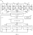
- FIG. 1 is a simplified diagram of an example of a dynamic testing system 100, in accordance with embodiments of the present disclosure.
- the testing system 100 may include one or more test stations 102, each of which may be configured to perform a test or conditions simulation through the application of forces and/or displacements to a test subject 103 (e.g., an automobile, a building, etc.) using hydraulic actuators 104, which are driven by flows 107 of hydraulic fluid.
- a test subject 103 e.g., an automobile, a building, etc.
- hydraulic actuators 104 which are driven by flows 107 of hydraulic fluid.
- the flows 107 may be provided based on hydraulic fluid flows 108 generated by one or more hydraulic power units (HPU's) 110.
- the system 100 may include an accumulator 116 that stores pressurized hydraulic fluid received from the HPU's 110 and discharges a hydraulic fluid flow 118 that may be used to form the flows 107 supplied to the test stations 102.
- the system 100 may include a distributor 120 that receives the hydraulic fluid flows from the HPU's 110 and/or the accumulator 116 and distributes the flows 107 of hydraulic fluid to the test stations 102. Other configurations of the system 100 may be used to supply the test stations 102 with the demanded hydraulic fluid flows 107.
- a system controller 126 may operate to control various aspects of the system 100 including functions of the HPU's 110, valving (e.g., valving of the accumulator and/or distributor) and/or other aspects of the system 100 to supply the test stations 102 with the demanded hydraulic fluid flows 107.
- valving e.g., valving of the accumulator and/or distributor
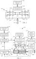
- FIG. 2 is a schematic diagram of an example of a test station 102, in accordance with embodiments of the present disclosure.
- the test station 102 includes a plurality of hydraulic actuators 104, such as hydraulic actuators 104A-D, that are configured to apply a force and/or drive a motion to the test subject 103.
- Each of the hydraulic actuators 104A-D is driven by a corresponding flow portion 106A-D of the hydraulic fluid flow 107 that is generated by one or more of the hydraulic power units 110 ( FIG. 1 ).
- a computing device 134 may be configured to generate a graphical user interface through which a user may interact with and/or control the test station 102, the execution of a test program, view data, and/or perform other tasks, such as through a series of communications with the test station controller 130, for example.
- One or more safety input valves 136 may control the high pressure hydraulic fluid flow 107 input to the test stations 102, such as in response to a control signal from the test station controller 130, the system controller 126, or another suitable device (e.g., emergency stop), for example.
- Each safety input valve 136 has a fully open state that provides a mostly unrestricted pathway for the hydraulic fluid flow 107 to travel to the test station 102.
- the valve 136 also has a closed or substantially closed state, in which the valve 136 blocks or substantially blocks the hydraulic fluid flow 107 to the test station 102.
- the solenoid of the valve 136 may have a default or deenergized state corresponding to the closed or substantially closed state.
- valve 136 When the safety input valve 136 is in the substantially closed state, an opening in the valve 136 allows the hydraulic fluid flow 107 to travel to the test station 102. However, the flow rate of the flow 106 is substantially restricted. This limits the flow rate of the hydraulic fluid 107 to the test station 102 and to the actuators 104 regardless of the settings of the control valves 132, thus limiting the speed at which the actuators 104 can move.
- the safety input valve 136 may be set to the substantially closed state by the test station controller 130, the system controller 126 or another controller of the system 100, such as in response to a detected malfunction or before operators enter the testing area where the actuators 104 and the test subject 103 are located, for example.
- the one or more safety input valves 136 provide a level of safety for the testing stations 102.
- FIG. 3 is a simplified diagram of an example of a test station 102, in accordance with embodiments of the present disclosure.
- the test station 102 includes a test station controller 130 and at least one hydraulic actuator 104 and its corresponding control valve 132. While only a single hydraulic actuator 104 and control valve 132 pair is shown in FIG. 3 to simplify the illustration, it is understood that the test station 102 may include two or more actuators 104 and corresponding control valves 132, such as indicated in FIG. 2 .
- the control valve 132 for each hydraulic actuator 104 operates to control a flow rate (e.g., gallons per minute) of the flow 106 of hydraulic fluid to the actuator 104 that is received from a high pressure source (e.g., HPU 110) 137, and the discharge of the flow 107' to a low pressure reservoir 138 (e.g., return to reservoir of HPU 110). Additionally, the control valve 132 controls the direction of the flow through the hydraulic actuator 104 to control the actuation that is applied to the test subject 130.
- a flow rate e.g., gallons per minute
- the hydraulic actuator 104 includes a cylinder 140 and an actuator rod 142 having a piston 144 that is contained within the cylinder 140.
- the cylinder 140 includes first and second ports 146 and 148, through which the flow 106 of hydraulic fluid travels.
- the valve 132 controls the direction of the hydraulic fluid flow 106 through the first and second ports 146 and 148 to control the direction of movement of the actuator rod 142 and the speed at which the actuator rod 142 moves relative to the cylinder 140 based on the flow rate of the hydraulic fluid flow 106.
- the control valve 132 may take on any suitable form. Examples of the control valve 132 include servo valves or solenoid valves that are configured to provide the variable flow rate and direction control described above. As indicated in FIG. 3 , the control valve 103 generally includes electronics 150, a valve body 152 and a valve body driver 154. The valve body 152 has an adjustable position that controls the direction and flow rate of the hydraulic fluid flow 106. The electronics 150 are configured to control the valve body driver 154 to adjust the position of the valve body 152 in response to an actuator command signal 156. For example, the valve body 152 may take the form of a spool and the valve body driver 154 may take the form of a servo. An example of this type of control valve 132 is described in U.S. Publication No. 2016/0123355 .
- control valve 132 includes a position sensor 158 that is configured to detect the position of the valve body 152, such as relative to a housing 160 of the valve 132.
- the electronics 150 are configured to output a position signal 162 that is indicative of the detected position of the valve body 152 and, thus, the flow rate and direction of the flow 106 through the valve 132.
- the position signal 162 may be used to facilitate various diagnostics on the system 100, such as diagnostics on the valve 132, the corresponding hydraulic actuator 104 and the test station 102, for example.
- each actuator 104 includes an actuation sensor 166 that is configured to sense a parameter of the actuation performed by the actuator 104, such as a displacement and/or a force, and issue a feedback signal 168 that is indicative of the sensed parameter.
- the actuation sensor 166 may comprise, for example, a displacement sensor 166A, such as a linear variable differential transformer that is configured to detect a displacement and/or movement of the actuator rod 142 relative to the cylinder 140 and produce a feedback signal 168A that is indicative of the detected displacement and/or movement, and/or a load cell 166B that is configured to detect a force applied by the actuator 104, such as a force applied by the actuator rod 142 to the test subject 103, and produce a feedback signal 168B that is indicative of the detected force, as indicated in FIG. 3 .
- a conventional conditioner circuit 169 may be used to process the signals 168A and/or 168B (e.g., amplify, filter, etc.) to produce the final feedback signal 168.
- An actuator controller 170 is configured to compare the reference signals 164 and the feedback signal 168 corresponding to each actuator 104 and issue a differential signal as the command signal 156 for the corresponding control valve 132. While the actuator controller 170 is illustrated in FIG. 3 as receiving a single reference signal 164 and issuing a single command signal 156 corresponding to the depicted actuator 104, the actuator controller 170 may be configured to receive multiple reference signals 164 from the test station controller 130 for each hydraulic actuator 104 of the test station 102 and corresponding feedback signals 168, and issue command signals 156 to control the valves 132.
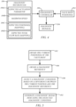
- FIG. 4 is a simplified diagram illustrating diagnostic functions that may be performed using a valve body position signal 162, in accordance with embodiments of the present disclosure.
- a diagnostics controller 180 represents at least one controller of the system 100, such as the system controller 126, the test station controller 130 and/or a separate controller of the system 100.
- the diagnostics controller 180 is generally configured to perform the method illustrated by the flowchart of FIG. 5 . While the illustrated method relates to diagnostics performed based on a valve body position of a single control valve 132, it is understood that the diagnostics controller 180 may be configured to perform the method on multiple valves 132.
- the diagnostics controller 180 obtains a current position 184 of the valve body 152 of a valve 132, and at 186, the diagnostic controller 180 obtains a diagnostic reference 188.
- the diagnostics controller 180 obtains the current position by receiving and possibly processing the corresponding position signal 162 ( FIG. 3 ), or by accessing the current position 184 from memory of the system 100, such as after the position signal 162 has been received and processed by a controller of the system 100.
- the diagnostic controller 180 may obtain the diagnostic reference 188 from memory of the system 100.
- “memory” corresponds to non-transitory computer-readable media.
- the current position 184 may take the form of a value that is obtained after processing the corresponding position signal 162.
- the position signal 162 indicates a position (value) of the valve body 152 relative to the housing 160 and is directly related to the flow rate of the flow 106, it may be beneficial to convert the position of the valve body 152 into value representing the flow rate, a value representing the speed of the actuator rod 142 of the corresponding actuator 104, or another value that allows for a comparison to the value of the diagnostic reference 188. Accordingly, the position 184 may take these or another suitable form.
- the diagnostics controller 180 detects a diagnostic condition based on a difference between the current position 184 and the diagnostic reference 188.
- the diagnostic controller 180 generates one or more diagnostic signals 194 that indicate the detected diagnostic condition, as indicated in FIG. 4 .
- the diagnostic signal 194 indicates the corresponding valve 132 and/or hydraulic actuator 104. This may be accomplished, for example, by including one or more identification codes in the signal 194, or based on the channel in which the diagnostic signal 194 is communicated (e.g., channel of a multiplexer). As a result, the signal 194 may allow a technician to easily target the malfunction, thereby saving time in correcting the malfunction and reducing downtime of the test station 102.
- the detected diagnostic condition may indicate a malfunction, such as when the difference meets a threshold condition, such as being greater than, equal to, or less than a predefined value.
- the malfunction may relate to a leak of hydraulic fluid at the valve 132, the hydraulic actuator 104, or another location along the pathway through which the flow 106 travels, a malfunction in the operation of the position sensor 158 and/or the actuation sensor 166, a malfunction in the operation of the valve electronics 150, a malfunction of the actuation performed by the hydraulic actuator 104, and/or another malfunction.
- a controller of the system 100 performs one or more safety measures when the diagnostic condition indicates a malfunction.
- the safety measure include a notification of the malfunction, such as through an audible and/or visible alarm or signal, the issuance of an electronic message, or another notification.
- the safety measure may include an action to prevent the further operation of the hydraulic actuator 104 and/or the test station 102.
- the actuator controller 170 may issue an actuator command 156 that directs the position of the valve body 152 to restrict or block the hydraulic fluid flow 106 to the actuator 104 and reduce the flow rate of the flow 106 to zero or close to zero (e.g., less than 0.5 gallons per minute) to clamp or substantially clamp the actuator rod 142 in its current position relative to the housing 140 and stop the actuation.
- a controller of the system 100 may also close one or more safety input valves 136 to limit the hydraulic fluid flow 106 to the test station 102. Other safety measures may also be employed.
- the diagnostic reference 188 includes an expected actuation parameter 188A corresponding to the valve body position 184.
- the actuation reference 188A indicates, for a given valve body position 184, an expected actuation parameter, such as expected speed and/or direction of movement of the actuator rod 142 relative to the cylinder 140 or an expected force applied by the hydraulic actuator 104.
- actuation parameters may be determined based on parameters of the hydraulic actuator (e.g., cross-sectional area of the cylinder 140 or piston 144) and the pressure of the fluid flow 106.
- the expected actuation parameter 188A may be determined through a real-time calculation or using a mapping of the expected actuation parameter 188A to positions of the valve body 152 stored in memory and accessible by the diagnostic controller 180.
- a diagnostic condition may be detected (step 190) based on a difference between the expected actuation parameter 188A and the feedback signal 168 relating to the corresponding actual actuation parameter detected or measured by the actuation sensor 166.
- the diagnostic condition may indicate a malfunction, such as a hydraulic fluid leak, a failure of the position sensor 158 and/or a failure of the actuation sensor 166.
- the diagnostics controller 180 may determine a difference between this measured actuation parameter and the expected direction and/or movement of the actuator rod 142 indicated by the actuation reference 188A to detect the diagnostic condition in step 190.
- the diagnostic signal 194 indicating the detected diagnostic condition may then be generated in step 192. If the difference exceeds a threshold condition, the diagnostic signal 194 may indicate a malfunction relating to a leak of hydraulic fluid, a malfunction of the position sensor 158, a malfunction of the displacement sensor 166B, a malfunction of the valve electronics 150, and/or another malfunction. For example, if the speed indicated by the feedback signal 166A is less than the expected speed 188A by a predefined amount, this would tend to indicate a possible leak of hydraulic fluid and/or another malfunction.
- the diagnostics controller 180 may determine a difference between this measured force and the expected force indicated by the actuation reference 188A to detect the diagnostic condition in step 190.
- the diagnostic signal indicating the detected diagnostic condition may then be generated in step 192.
- the diagnostic signal 194 indicating the detected diagnostic condition may then be generated in step 192. If the difference exceeds a threshold condition, the diagnostic signal 194 may indicate a malfunction relating to a leak of hydraulic fluid, a malfunction of the position sensor 158, a malfunction of the load cell 166B, a malfunction of the valve electronics 150, and/or another malfunction. For example, if the force indicated by the feedback signal 166B is less than the expected force 188A by a predefined amount, this would tend to indicate a possible leak of hydraulic fluid and/or another malfunction.
- the diagnostic reference 188 may include a maximum speed 188B for the actuator rod 142 relative to the cylinder 140 stored in memory.
- the maximum speed 188B is directly related to the flow rate of the hydraulic fluid flow 106 and parameters of the hydraulic actuator (e.g., cross-sectional area of the cylinder 140 or piston 144).
- the maximum speed 188B diagnostic reference may take the form of a value corresponding to a speed limit of the actuator rod 142 or a flow rate of the hydraulic fluid flow.
- the maximum speed 188B may be set by a user and stored in memory based on parameters of the hydraulic actuator 104 (e.g., speed and/or force limit), a location or function performed by the hydraulic actuator 104, and/or a state of the test station 102.
- the maximum speed 188B may have a high setting for when the test station 102 is performing a test program, and a relatively low setting (e.g., less than about 10-15 millimeters per second or a corresponding flow rate) when workers are in the vicinity of the hydraulic actuator 104.
- a diagnostic condition may be detected (step 190) based on a difference between the maximum speed 188B and the valve body position 184.
- the maximum speed 188B and/or the valve body position 184 may be converted as necessary to allow for a direct comparison of the values, such that the difference may be determined.
- the diagnostic signal 194 may indicate an overspeed malfunction of the hydraulic actuator 104.
- a controller of the system 100 may then perform a safety measure, such as discussed above to stop or limit movement of the actuator rod 142.
- a diagnostic condition is detected using an expected position 188C diagnostic reference relating to an expected position of the valve body 152 and an expected flow rate of the hydraulic fluid flow 106 through one of the valves 132 of the test station 102 at a given time during the performance of a test program.
- a diagnostic condition such as a leak of hydraulic fluid, may be detected (step 190) when a difference between the current valve body position 184 and the expected position 188C meets a threshold condition. For example, when the current valve body position 184 indicates a flow rate of the hydraulic fluid flow 106 that is greater than the flow rate indicated by the expected position 188C by a predefined threshold, this may indicate the existence of a leak of hydraulic fluid in the pathway through the valve 132 and the hydraulic actuator 104.
- the expected position 188C may be obtained (step 186) using various techniques. In one embodiment, the expected position 188C is obtained based on one or more prior performances of the test program.
- the position of the valve body 152 of each valve 132 of the test station 102 is adjusted over time in response to the actuation command 156 to adjust the flow rate and direction of the hydraulic fluid flow 106 and cause the corresponding hydraulic actuator 104 to perform a desired actuation on the test subject 103. Since the test program may be repeated numerous times by the test station, the valve body 152 of each of the valves 132 will, barring a significant malfunction, substantially repeat a pattern of positions over the period of time that the test program is performed. An example of such a pattern 196 of a position 184 of a valve body 152 of a control valve 132 over time during the performance of a test program is illustrated in FIG. 6 .
- a mapping of the pattern 196 of the valve body position 184 over the test period is formed, from which the expected valve body positions 188C may be obtained in step 186 of the method.
- the mapping is stored in memory and may take on any suitable form.
- the mapping includes a series of samplings of the valve body position 184 in the pattern 196 at various times during the performance of the test.
- FIG. 7 is a flowchart illustrating an example of a method for forming the mapping, in accordance with embodiments of the present disclosure.
- a plurality of command signals 156 are generated over a test period during the performance of a test program.
- the command signals 156 control the position of the valve body 152, which controls the actuation performed by the hydraulic actuator 104.
- a plurality of the positions 184 of the valve body 152 are obtained over the test period, such as based on the position signal 162 from the position sensor 158, for example.
- the plurality of obtained positions 184 are then mapped over the test period, and the mapping is stored in memory at 206.
- embodiments of the method step 186 include the diagnostic controller 180 obtaining the valve body position 184 at a given time t 1 during the performance of a test program.
- the expected position 188C Pi corresponding to the time t 1 is obtained from the mapping, as indicated in FIG. 6 .
- the diagnostic signal 194 is generated (step 192) that indicates a diagnostic condition, which is detected (step 190) based on a difference between the current position 184 and the expected position 188C (Pi).
- the diagnostic condition may be a malfunction, such as a leak in the fluid path through the valve 132 and the corresponding hydraulic actuator 194, for example.
- the system controller 126 or another controller of the system 100 may perform a safety measure, such as one or more of the safety measures described above.
- the safety measure may include closing the safety input valve 136 and/or issuing actuator command signals 156 that adjust the valve body 152 to a position that prevents or substantially prevents the flow 106 from traveling through the valve 132.
- Additional embodiments of the present disclosure relate to the detection of a malfunction, such as a leak of hydraulic fluid, in the test station 102 based on an estimated total flow rate of the hydraulic fluid flows 106 (e.g., flows 106A-D in FIG. 2 ) through the control valves 132 at a given time during the performance of a test program and an expected total flow rate 188D diagnostic reference ( FIG. 4 ) corresponding to an expected total flow rate of the hydraulic fluid flows 106 at the time.
- a malfunction such as a leak of hydraulic fluid
- FIG. 8 is a flowchart illustrating a method performed by the diagnostic controller 180 to control the system 100, such as a test station 102 of the system 100, in accordance with this embodiment of the present disclosure that may be performed by the system 100.
- the current positions 184 of the control valves 132 of the test station 102 are obtained using the diagnostic controller 180.
- a total flow rate of the hydraulic fluid flows 106 through the control valves 132 is estimated at the time.
- the estimated total flow rate may be a value that is indicative of or related to the total of the flow rates of the hydraulic fluid flows 106 through the individual control valves 132 or the hydraulic fluid flow 107 input to the test station 102.
- the estimated total flow rate of the hydraulic fluid flows 106 through the control valves 132 at the time is determined based on the current positions 184 of the corresponding valve bodies 152 at the time, which may be indicated by the corresponding position signals 162.
- the estimated total flow rate may be determined based on a sum of the current positions 184 at the time, which may be calculated by the diagnostic controller 180.
- the expected total flow rate 188D is obtained by the diagnostic controller 180, such as from memory of the system 100.
- the expected total flow rate 188D is determined based on one or more prior performances of the test program.
- the expected total flow rate 188D may be obtained from or represented by a total flow rate mapping of the flow rate 107 to the test station 102 over time during the performance of the test program.
- the total flow rate mapping may be stored in memory that is accessible to the diagnostic controller 180.
- the system 100 may include a flowmeter 210 that is configured to measure the flow rate of the hydraulic fluid flow 107 traveling through the test station 102, as indicated in FIG. 2 .
- the total flow rate mapping may be established, for example, by sampling the measured flow rate of the hydraulic fluid flow 107 during the performance of the test program.
- the expected total flow rate 188D may be determined based on the mapping of the pattern 196 of valve body positions 184 during one or more prior performances of the test discussed above.
- the expected position mappings may either be summed together to form the total flow rate mapping, or the diagnostic controller 180 may use the expected position mappings to obtain an expected position of each of the valve bodies 152 at the time. The expected positions may then be summed together by the diagnostic controller 180 to obtain the expected total flow rate 188D for the time in step 214.
- a diagnostic condition is detected based on a difference between the estimated and expected total flow rates, and a diagnostic signal 194 that is indicative of the diagnostic condition is generated at 218.
- the diagnostic condition may be a malfunction, such as a leak in the fluid path through the valves 132 and the corresponding hydraulic actuators 194, for example.
- the system controller 126 or another controller of the system 100 may perform a safety measure, such as one or more of the safety measures described above.
- the safety measure may include closing the safety input valve 136 and/or issuing actuator command signals 156 that adjust the valve bodies 152 to positions that prevent or substantially prevent the flows 106 from traveling through the valves 132.
- the controllers of the system 100 may take on any suitable form to control the various functions described herein.
- the controllers of the system 100 may take the form of the example controller 220 shown in FIG. 9 .
- the controller 220 may include one or more processors 222 and memory 224, which may be local memory or memory that is accessible to the controller 220.
- the one or more processors 222 are configured to perform various functions described herein in response to the execution of instructions contained in the memory 224, such as a test program, for example.
- the one or more processors 222 may be components of one or more computer-based systems, and may include one or more control circuits, microprocessor-based engine control systems, and/or one or more programmable hardware components, such as a field programmable gate array (FPGA).
- the memory 224 represents local and/or remote memory or computer-readable media. As used herein, such memory 224 comprises any suitable patent subject matter eligible computer-readable media and does not include transitory waves or signals. Examples of the memory 224 include conventional data storage devices, such as hard disks, CD-ROMs, optical storage devices, magnetic storage devices and/or other suitable data storage devices.
- the controller 220 may include circuitry 226 for use by the one or more processors 222 to receive input signals 228 (e.g., sensor signals), issue control signals 230 (e.g., signals 156, 164, etc.) and/or communicate data 232, such as in response to the execution of the instructions stored in the memory 224 by the one or more processors 222.
- input signals 228 e.g., sensor signals
- issue control signals 230 e.g., signals 156, 164, etc.
- data 232 such as in response to the execution of the instructions stored in the memory 224 by the one or more processors 222.
Landscapes
- Engineering & Computer Science (AREA)
- Physics & Mathematics (AREA)
- Fluid Mechanics (AREA)
- Mechanical Engineering (AREA)
- General Engineering & Computer Science (AREA)
- General Physics & Mathematics (AREA)
- Chemical & Material Sciences (AREA)
- Analytical Chemistry (AREA)
- Automation & Control Theory (AREA)
- Fluid-Pressure Circuits (AREA)
- Testing Of Devices, Machine Parts, Or Other Structures Thereof (AREA)
- Control Of Position Or Direction (AREA)
Abstract
A dynamic testing system includes a test station and at least one controller. The test station includes a hydraulic actuator configured to drive an actuation of a test subject using a hydraulic fluid flow, and a control valve that includes a housing, a valve body contained within the housing having a position that controls a flow rate and direction of the hydraulic fluid flow, a valve body driver configured to adjust the position of the valve body based on a reference signal, and a valve position sensor configured to output a position signal that is indicative of the position of the valve body. The at least one controller is configured to obtain a current position of the valve body using the position signal, obtain a diagnostic reference, detect a diagnostic condition based on a difference between the current position and the diagnostic reference, and generate a diagnostic signal.
Description
- This application claims the benefit of priority from
U.S. Provisional Patent Application No. 63/580,102 filed September 1, 2023 - Embodiments of the present disclosure generally relate to test stations of dynamic testing systems and, more particularly, to speed control of a hydraulic actuator of a test station.
- Dynamic testing systems, such as those developed by MTS Systems Corporation, include test stations that perform various tests through the application of loads and displacements to a test subject using hydraulic actuators in accordance with a test program. Test stations may include, for example, a vehicle testing station that applies simulated driving conditions to a mobile vehicle, or a building testing station that applies simulated seismic activity to a building.
- The actuators of the test stations are driven by hydraulic fluid flows. The actuations performed by each actuator are controlled using a control valve (e.g., proportional control valve) that regulates the flow rate and direction of the hydraulic fluid flow through the actuator.
- Test stations may experience various types of malfunctions. Some of these malfunctions may relate to leaks along hydraulic fluid flow paths, such as at the control valves, the hydraulic actuators or other components of the test station. Such leaks reduce the efficiency at which the test station operates. Additionally, such leaks may be an early indication of the potential for a more serious failure.
- Other possible malfunctions relate to the accuracy at which the hydraulic actuators perform programmed or commanded actuations. For example, it is important that movement actuations of a test subject accurately reflect the desired movement indicated by the test program to ensure that the test is properly carried out and produces valid test results. The accuracy at which the hydraulic actuators perform programmed or commanded actuations is also important for safety reasons, such as by ensuring that maximum speed of the actuations does not exceed a safety threshold when workers are present.
- Accordingly, it is important to detect these and other test station malfunctions as early as possible.
- Embodiments of the present disclosure relate to diagnostic methods for dynamic testing systems and dynamic testing systems configured to perform the methods.
- One embodiment of a dynamic testing system includes a test station and at least one controller. The test station includes a hydraulic actuator configured to drive an actuation of a test subject using a hydraulic fluid flow, and a control valve. The control valve includes a housing, a valve body contained within the housing having a position that controls a flow rate and direction of the hydraulic fluid flow, a valve body driver configured to adjust the position of the valve body based on a reference signal, and a valve position sensor configured to output a position signal that is indicative of the position of the valve body. The at least one controller is configured to obtain a current position of the valve body using the position signal, obtain a diagnostic reference, detect a diagnostic condition based on a difference between the current position and the diagnostic reference, and generate a diagnostic signal indicating the detected diagnostic condition.
- In some embodiments, the hydraulic actuator includes a cylinder and an actuator rod including a piston contained within the cylinder, and movement of the piston and the actuator rod relative to the cylinder drives the actuation.
- In some embodiments, the housing of the control valve includes an inlet port coupled to a supply of high pressure hydraulic fluid, an outlet port coupled to a low pressure return reservoir, a first port coupled to a first working volume formed by an interior of the cylinder and the piston and a second port coupled to a second working volume formed by the interior of the cylinder and the piston, and the position of the valve body directs the hydraulic fluid flow received at the inlet port to one of the first and second ports or neither of the first and second ports and controls a flow rate of the hydraulic fluid flow.
- In some embodiments, the test station includes an actuation sensor configured to generate a feedback signal that is indicative of a parameter of the actuation, the at least one controller is configured to generate a control reference signal corresponding to a desired actuation based on a test program and generate an actuator command signal based on a difference between the control reference signal and the feedback signal, and the actuator command signal directs the valve body driver to adjust the position of the valve body.
- In some embodiments, the diagnostic reference includes a maximum speed of the actuator rod.
- In some embodiments, the diagnostic reference includes an actuation parameter relating to the feedback signal.
- In some embodiments, the actuation sensor comprises a displacement sensor, the feedback signal indicates a direction of movement or speed of the actuator rod relative to the cylinder and the actuation parameter relates to the direction of movement or speed indicated by the feedback signal.
- In some embodiments, the actuation sensor comprises a load cell, the feedback signal indicates a force applied by the actuator and the actuation parameter relates to the force indicated by the feedback signal.
- In some embodiments, the diagnostic condition comprises a malfunction of a displacement sensor, a malfunction of an actuation sensor, or a leak of hydraulic fluid.
- In some embodiments, the current position of the valve body is obtained by the at least one controller during a performance of a test program by the test station and the diagnostic reference includes an expected position of the valve body that is based on at least one prior performance of the test program.
- In some embodiments, the expected position of the valve body is obtained based on a mapping of positions of the valve body over time during the at least one prior performance of the test program stored in a computer-readable medium.
- In some embodiments, the at least one controller forms the mapping through a process comprising generating a plurality of the actuator command signals over a test period during a performance of the test program, obtaining a plurality of positions of the valve body over the test period, forming the mapping of the positions over the test period, and storing the mapping in the computer-readable medium.
- In some embodiments, the valve body driver comprises a servo or a solenoid and the valve body comprises a spool or a piston.
- In some embodiments, the at least one controller is configured to perform a safety measure when the difference meets a threshold condition.
- In some embodiments, the safety measure includes issuing an audible and/or visible alarm or signal, issuing an electronic notification, directing the valve body driver to adjust the position of the valve body to restrict or block the hydraulic fluid flow to the hydraulic actuator, and/or closing a safety input valve controlling the flow of the hydraulic fluid to the hydraulic actuator.
- One method controls a dynamic testing system, which includes a test station and at least one controller. The test station includes a hydraulic actuator configured to drive an actuation of a test subject using a hydraulic fluid flow, and a control valve. The control valve includes a housing, a valve body contained within the housing having a position that controls a flow rate and direction of the hydraulic fluid flow, a valve body driver configured to adjust the position of the valve body based on a reference signal, and a valve position sensor configured to output a position signal that is indicative of the position of the valve body. In the method, which is performed by the at least one controller, a current position of the valve body is obtained using the position signal and a diagnostic reference is obtained. A diagnostic condition is detected based on a difference between the current position and the diagnostic reference, and a diagnostic signal indicating the detected diagnostic condition is generated.
- In some embodiments, the hydraulic actuator includes a cylinder and an actuator rod including a piston contained within the cylinder, and movement of the piston and the actuator rod relative to the cylinder drives the actuation.
- In some embodiments, the housing of the control valve includes an inlet port coupled to a supply of high pressure hydraulic fluid, an outlet port coupled to a low pressure return reservoir, a first port coupled to a first working volume formed by an interior of the cylinder and the piston and a second port coupled to a second working volume formed by the interior of the cylinder and the piston.
- In some embodiments, the position of the valve body directs the hydraulic fluid flow received at the inlet port to one of the first and second ports or neither of the first and second ports and controls a flow rate of the hydraulic fluid flow.
- In some embodiments, the test station includes an actuation sensor configured to generate a feedback signal that is indicative of a parameter of the actuation, and the method includes generating a control reference signal corresponding to a desired actuation based on a test program and generating an actuator command signal based on a difference between the control reference signal and the feedback signal. In some embodiments, the actuator command signal is used to direct the valve body driver to adjust the position of the valve body.
- In some embodiments, the diagnostic reference includes a maximum speed of the actuator rod.
- In some embodiments, the diagnostic reference includes an actuation parameter relating to the feedback signal.
- In some embodiments, the actuation sensor comprises a displacement sensor, the feedback signal indicates a direction of movement or speed of the actuator rod relative to the cylinder and the actuation parameter relates to the direction of movement or speed indicated by the feedback signal.
- In some embodiments, the actuation sensor comprises a load cell, the feedback signal indicates a force applied by the actuator and the actuation parameter relates to the force indicated by the feedback signal.
- In some embodiments, the diagnostic condition comprises a malfunction of a displacement sensor, a malfunction of an actuation sensor, or a leak of hydraulic fluid.
- In some embodiments, the current position of the valve body is obtained by the at least one controller during a performance of a test program by the test station and the diagnostic reference includes an expected position of the valve body that is based on at least one prior performance of the test program.
- In some embodiments, the expected position of the valve body is obtained based on a mapping of positions of the valve body over time during the at least one prior performance of the test program stored in a computer-readable medium.
- In some embodiments, the method includes forming the mapping using the at least one controller comprising generating a plurality of the actuator command signals over a test period during a performance of the test program, obtaining a plurality of positions of the valve body over the test period, forming the mapping of the positions over the test period and storing the mapping in the computer-readable medium.
- In some embodiments, the valve body driver comprises a servo or a solenoid and the valve body comprises a spool or a piston.
- In some embodiments, the method includes performing a safety measure when the difference meets a threshold condition.
- In some embodiments, the safety measure includes issuing an audible and/or visible alarm or signal, issuing an electronic notification, directing the valve body driver to adjust the position of the valve body to restrict or block the hydraulic fluid flow to the hydraulic actuator, and/or closing a safety input valve controlling the flow of the hydraulic fluid to the hydraulic actuator.
- Another embodiment of a dynamic testing system includes a test station and at least one controller. The test station includes a plurality of hydraulic actuators, each configured to receive a hydraulic fluid flow and drive an actuation of a test subject using the hydraulic fluid flow during a test, and a plurality of control valves, each control valve corresponding to one of the hydraulic actuators. Each control valve includes a housing, a valve body contained within the housing having a position that controls a flow rate and direction of the corresponding hydraulic fluid flow, a valve body driver configured to adjust the position of the valve body based on a reference signal, and a valve position sensor configured to output a position signal that is indicative of the position of the valve body. The at least one controller is configured to obtain a current position of the valve body of each of the control valves at a time during a performance of a test program using the corresponding position signals, estimate a total flow rate of the hydraulic fluid flows at the time based on the obtained current positions of the control valves, obtain an expected total flow rate corresponding to the time based on at least one prior performance of the test program, and detect a diagnostic condition based on a difference between the estimated total flow rate and the expected total flow rate, and generate a diagnostic signal indicating the detected diagnostic condition.
- In some embodiments, the system includes a mapping of a total flow rate of the hydraulic fluid flows during the at least one prior performance of the test program and the expected total flow rate corresponds to the total flow rate indicated by the mapping at the time.
- In some embodiments, the at least one controller is configured to obtain the expected total flow rate corresponding to the time using a process comprising for each control valve, obtaining an expected position of the valve body corresponding to the time based on the at least one prior performance of the test program, and calculating the expected total flow rate of the hydraulic fluid flows based on a sum of the expected positions.
- In some embodiments, each of the hydraulic actuators includes a cylinder and an actuator rod including a piston contained within the cylinder, and movement of the piston and the actuator rod relative to the cylinder drives the actuation.
- In some embodiments, the housing each of the control valves includes an inlet port coupled to a supply of high pressure hydraulic fluid, an outlet port coupled to a low pressure return reservoir, a first port coupled to a first working volume formed by an interior of the cylinder and the piston and a second port coupled to a second working volume formed by the interior of the cylinder and the piston.
- In some embodiments, for each control valve, the position of the valve body directs the hydraulic fluid flow received at the inlet port to one of the first and second ports or neither of the first and second ports and controls a flow rate of the hydraulic fluid flow.
- In some embodiments, each hydraulic actuator includes a corresponding actuation sensor configured to generate a feedback signal that is indicative of a parameter of the corresponding actuation, and the at least one controller is configured to generate a control reference signal for each control valve corresponding to a desired actuation by the corresponding controller based on a test program and generate an actuator command signal for each control reference signal based on a difference between the control reference signal and the corresponding feedback signal. Each actuator command signal directs the corresponding valve body driver to adjust the position of the valve body.
- In some embodiments, the at least one controller is configured to perform a safety measure when the difference meets a threshold condition.
- In some embodiments, the safety measure includes issuing an audible and/or visible alarm or signal, issuing an electronic notification, directing the valve body drivers to adjust the position of the corresponding valve body to restrict or block the hydraulic fluid flow to the hydraulic actuator, and/or closing a safety input valve controlling the hydraulic fluid flows to the hydraulic actuators.
- Another method controls a dynamic testing system, which includes a test station and at least one controller. The test station includes a plurality of hydraulic actuators, each configured to receive a hydraulic fluid flow and drive an actuation of a test subject using the hydraulic fluid flow during a test, and a plurality of control valves, each corresponding to one of the hydraulic actuators. Each control valve includes a housing, a valve body contained within the housing having a position that controls a flow rate and direction of the corresponding hydraulic fluid flow, a valve body driver configured to adjust the position of the valve body based on a reference signal, and a valve position sensor configured to output a position signal that is indicative of the position of the valve body. The method is performed by the at least one controller and includes obtaining a current position of the valve body of each of the control valves at a time using the corresponding position signals, estimating a total flow rate of the hydraulic fluid flows at the time based on the obtained current positions of the control valves, obtaining an expected total flow rate corresponding to the time based on at least one prior performance of the test program, detecting a diagnostic condition based on a difference between the estimated total flow rate and the expected total flow rate, and generating a diagnostic signal indicating the detected diagnostic condition.
- In some embodiments, the system includes a mapping of a total flow rate of the hydraulic fluid flows during the at least one prior performance of the test program and the expected total flow rate corresponds to the total flow rate indicated by the mapping at the time.
- In some embodiments, obtaining the expected total flow rate corresponding to the time comprises for each control valve, obtaining an expected position of the valve body corresponding to the time based on the at least one prior performance of the test program and calculating the expected total flow rate of the hydraulic fluid flows based on a sum of the expected positions.
- In some embodiments, each of the hydraulic actuators includes a cylinder and an actuator rod including a piston contained within the cylinder, wherein movement of the piston and the actuator rod relative to the cylinder drives the actuation.
- In some embodiments, the housing each of the control valves includes an inlet port coupled to a supply of high pressure hydraulic fluid, an outlet port coupled to a low pressure return reservoir, a first port coupled to a first working volume formed by an interior of the cylinder and the piston and a second port coupled to a second working volume formed by the interior of the cylinder and the piston. For each control valve, the position of the valve body directs the hydraulic fluid flow received at the inlet port to one of the first and second ports or neither of the first and second ports and controls a flow rate of the hydraulic fluid flow.
- In some embodiments, each hydraulic actuator includes a corresponding actuation sensor configured to generate a feedback signal that is indicative of a parameter of the corresponding actuation.
- In some embodiments, the at least one controller is configured to generate a control reference signal for each control valve corresponding to a desired actuation by the corresponding controller based on a test program and generate an actuator command signal for each control reference signal based on a difference between the control reference signal and the corresponding feedback signal. Each actuator command signal directs the corresponding valve body driver to adjust the position of the valve body.
- In some embodiments, the method includes performing a safety measure when the difference meets a threshold condition.
- In some embodiments, the safety measure includes issuing an audible and/or visible alarm or signal, issuing an electronic notification, directing the valve body drivers to adjust the position of the corresponding valve body to restrict or block the hydraulic fluid flow to the hydraulic actuator, and/or closing a safety input valve controlling the hydraulic fluid flows to the hydraulic actuators.
- This Summary is provided to introduce a selection of concepts in a simplified form that are further described below in the Detailed Description. This Summary is not intended to identify key features or essential features of the claimed subject matter, nor is it intended to be used as an aid in determining the scope of the claimed subject matter. The claimed subject matter is not limited to implementations that solve any or all disadvantages noted in the Background.
-
-
FIG. 1 is a simplified diagram of an example of a dynamic testing system, in accordance with embodiments of the present disclosure. -
FIGS. 2 and 3 are schematic diagrams of an example of a test station, in accordance with embodiments of the present disclosure. -
FIG. 4 is a simplified diagram illustrating diagnostic functions that may be performed using a valve body position signal, in accordance with embodiments of the present disclosure. -
FIG. 5 is a flowchart illustrating a diagnostics method, in accordance with embodiments of the present disclosure. -
FIG. 6 is a chart illustrating a pattern of valve body positions over time during the performance of a test program, in accordance with embodiments of the present disclosure. -
FIG. 7 is a flowchart illustrating an example of a method for forming the mapping, in accordance with embodiments of the present disclosure. -
FIG. 8 is a flowchart illustrating a method of controlling a dynamic testing system, in accordance with embodiments of the present disclosure. -
FIG. 9 is a simplified diagram of an example of a controller, in accordance with embodiments of the present disclosure. - Embodiments of the present disclosure are described more fully hereinafter with reference to the accompanying drawings. Elements that are identified using the same or similar reference characters refer to the same or similar elements. The various embodiments of the present disclosure may, however, be embodied in many different forms and should not be construed as limited to the embodiments set forth herein. Rather, these embodiments are provided so that this disclosure will be thorough and complete, and will fully convey the scope of the present disclosure to those skilled in the art.
- Functions recited herein may be performed by a single controller, multiple controllers, or at least one controller. As used herein, when one or more functions are described as being performed by "a controller," such as a specific controller, one or more controllers, or at least one controller, embodiments include the performance of the function(s) by a single controller or processor or multiple controllers or processors, unless otherwise specified. Furthermore, as used herein, when multiple functions are performed by at least one controller, all of the functions may be performed by a single controller, or some functions may be performed by one controller and other functions may be performed by another controller. Thus, the performance of one or more functions by at least one controller does not require that all of the functions are performed by each of the controllers.
-
FIG. 1 is a simplified diagram of an example of adynamic testing system 100, in accordance with embodiments of the present disclosure. Thetesting system 100 may include one ormore test stations 102, each of which may be configured to perform a test or conditions simulation through the application of forces and/or displacements to a test subject 103 (e.g., an automobile, a building, etc.) usinghydraulic actuators 104, which are driven byflows 107 of hydraulic fluid. - The
flows 107 may be provided based on hydraulic fluid flows 108 generated by one or more hydraulic power units (HPU's) 110. Thesystem 100 may include anaccumulator 116 that stores pressurized hydraulic fluid received from the HPU's 110 and discharges ahydraulic fluid flow 118 that may be used to form theflows 107 supplied to thetest stations 102. Thesystem 100 may include adistributor 120 that receives the hydraulic fluid flows from the HPU's 110 and/or theaccumulator 116 and distributes theflows 107 of hydraulic fluid to thetest stations 102. Other configurations of thesystem 100 may be used to supply thetest stations 102 with the demanded hydraulic fluid flows 107. - The
system 100 may be a closed system, in which the low pressure hydraulic fluid flows 107' discharged from thetest stations 102 are returned, such as a combinedreturn flow 124 through thehydraulic distribution system 120 back to the HPU's 110, for example. - A
system controller 126 may operate to control various aspects of thesystem 100 including functions of the HPU's 110, valving (e.g., valving of the accumulator and/or distributor) and/or other aspects of thesystem 100 to supply thetest stations 102 with the demanded hydraulic fluid flows 107. -
FIG. 2 is a schematic diagram of an example of atest station 102, in accordance with embodiments of the present disclosure. As mentioned above, thetest station 102 includes a plurality ofhydraulic actuators 104, such ashydraulic actuators 104A-D, that are configured to apply a force and/or drive a motion to thetest subject 103. Each of thehydraulic actuators 104A-D is driven by acorresponding flow portion 106A-D of thehydraulic fluid flow 107 that is generated by one or more of the hydraulic power units 110 (FIG. 1 ). - Each
test station 102 may include atest station controller 130, which is generally configured to perform a test on the test subject 103 based on the execution of a test program stored in a non-transitory computer-readable medium, for example. Thetest station controller 130 controls theactuators 104 to apply forces and/or motions in a conventional manner to the test subject 103 in response to the execution of the test program through the control of the hydraulic fluid flows 106A-D usingcorresponding control valves 132. - A
computing device 134 may be configured to generate a graphical user interface through which a user may interact with and/or control thetest station 102, the execution of a test program, view data, and/or perform other tasks, such as through a series of communications with thetest station controller 130, for example. - One or more
safety input valves 136, such as solenoid valves, may control the high pressurehydraulic fluid flow 107 input to thetest stations 102, such as in response to a control signal from thetest station controller 130, thesystem controller 126, or another suitable device (e.g., emergency stop), for example. Eachsafety input valve 136 has a fully open state that provides a mostly unrestricted pathway for thehydraulic fluid flow 107 to travel to thetest station 102. Thevalve 136 also has a closed or substantially closed state, in which thevalve 136 blocks or substantially blocks thehydraulic fluid flow 107 to thetest station 102. The solenoid of thevalve 136 may have a default or deenergized state corresponding to the closed or substantially closed state. - When the
safety input valve 136 is in the substantially closed state, an opening in thevalve 136 allows thehydraulic fluid flow 107 to travel to thetest station 102. However, the flow rate of theflow 106 is substantially restricted. This limits the flow rate of thehydraulic fluid 107 to thetest station 102 and to theactuators 104 regardless of the settings of thecontrol valves 132, thus limiting the speed at which theactuators 104 can move. - The
safety input valve 136 may be set to the substantially closed state by thetest station controller 130, thesystem controller 126 or another controller of thesystem 100, such as in response to a detected malfunction or before operators enter the testing area where theactuators 104 and thetest subject 103 are located, for example. Thus, the one or moresafety input valves 136 provide a level of safety for thetesting stations 102. -
FIG. 3 is a simplified diagram of an example of atest station 102, in accordance with embodiments of the present disclosure. As discussed above, thetest station 102 includes atest station controller 130 and at least onehydraulic actuator 104 and itscorresponding control valve 132. While only a singlehydraulic actuator 104 andcontrol valve 132 pair is shown inFIG. 3 to simplify the illustration, it is understood that thetest station 102 may include two ormore actuators 104 andcorresponding control valves 132, such as indicated inFIG. 2 . - The
control valve 132 for eachhydraulic actuator 104 operates to control a flow rate (e.g., gallons per minute) of theflow 106 of hydraulic fluid to theactuator 104 that is received from a high pressure source (e.g., HPU 110) 137, and the discharge of the flow 107' to a low pressure reservoir 138 (e.g., return to reservoir of HPU 110). Additionally, thecontrol valve 132 controls the direction of the flow through thehydraulic actuator 104 to control the actuation that is applied to thetest subject 130. - In one example, the
hydraulic actuator 104 includes acylinder 140 and anactuator rod 142 having apiston 144 that is contained within thecylinder 140. Thecylinder 140 includes first andsecond ports flow 106 of hydraulic fluid travels. Thevalve 132 controls the direction of thehydraulic fluid flow 106 through the first andsecond ports actuator rod 142 and the speed at which theactuator rod 142 moves relative to thecylinder 140 based on the flow rate of thehydraulic fluid flow 106. - The
control valve 132 may take on any suitable form. Examples of thecontrol valve 132 include servo valves or solenoid valves that are configured to provide the variable flow rate and direction control described above. As indicated inFIG. 3 , thecontrol valve 103 generally includeselectronics 150, avalve body 152 and avalve body driver 154. Thevalve body 152 has an adjustable position that controls the direction and flow rate of thehydraulic fluid flow 106. Theelectronics 150 are configured to control thevalve body driver 154 to adjust the position of thevalve body 152 in response to anactuator command signal 156. For example, thevalve body 152 may take the form of a spool and thevalve body driver 154 may take the form of a servo. An example of this type ofcontrol valve 132 is described inU.S. Publication No. 2016/0123355 . - In some embodiments, the
control valve 132 includes aposition sensor 158 that is configured to detect the position of thevalve body 152, such as relative to ahousing 160 of thevalve 132. Theelectronics 150 are configured to output aposition signal 162 that is indicative of the detected position of thevalve body 152 and, thus, the flow rate and direction of theflow 106 through thevalve 132. As discussed below, the position signal 162 may be used to facilitate various diagnostics on thesystem 100, such as diagnostics on thevalve 132, the correspondinghydraulic actuator 104 and thetest station 102, for example. - During the execution of a test program, the
test station controller 130 issues referencesignals 164 relating to desired actuations that are to be performed by thehydraulic actuators 104 on thetest subject 103. Eachactuator 104 includes anactuation sensor 166 that is configured to sense a parameter of the actuation performed by theactuator 104, such as a displacement and/or a force, and issue afeedback signal 168 that is indicative of the sensed parameter. Theactuation sensor 166 may comprise, for example, adisplacement sensor 166A, such as a linear variable differential transformer that is configured to detect a displacement and/or movement of theactuator rod 142 relative to thecylinder 140 and produce afeedback signal 168A that is indicative of the detected displacement and/or movement, and/or aload cell 166B that is configured to detect a force applied by theactuator 104, such as a force applied by theactuator rod 142 to thetest subject 103, and produce afeedback signal 168B that is indicative of the detected force, as indicated inFIG. 3 . Aconventional conditioner circuit 169 may be used to process thesignals 168A and/or 168B (e.g., amplify, filter, etc.) to produce thefinal feedback signal 168. - An
actuator controller 170 is configured to compare the reference signals 164 and thefeedback signal 168 corresponding to each actuator 104 and issue a differential signal as thecommand signal 156 for thecorresponding control valve 132. While theactuator controller 170 is illustrated inFIG. 3 as receiving asingle reference signal 164 and issuing asingle command signal 156 corresponding to the depictedactuator 104, theactuator controller 170 may be configured to receivemultiple reference signals 164 from thetest station controller 130 for eachhydraulic actuator 104 of thetest station 102 and corresponding feedback signals 168, and issue command signals 156 to control thevalves 132. - Some embodiments of the present disclosure relate to dynamic testing system diagnostics using the position signals 162 issued by the
control valves 132.FIG. 4 is a simplified diagram illustrating diagnostic functions that may be performed using a valve body position signal 162, in accordance with embodiments of the present disclosure. Adiagnostics controller 180 represents at least one controller of thesystem 100, such as thesystem controller 126, thetest station controller 130 and/or a separate controller of thesystem 100. Thediagnostics controller 180 is generally configured to perform the method illustrated by the flowchart ofFIG. 5 . While the illustrated method relates to diagnostics performed based on a valve body position of asingle control valve 132, it is understood that thediagnostics controller 180 may be configured to perform the method onmultiple valves 132. - At 182 of the method, the
diagnostics controller 180 obtains acurrent position 184 of thevalve body 152 of avalve 132, and at 186, thediagnostic controller 180 obtains adiagnostic reference 188. In some embodiments, thediagnostics controller 180 obtains the current position by receiving and possibly processing the corresponding position signal 162 (FIG. 3 ), or by accessing thecurrent position 184 from memory of thesystem 100, such as after the position signal 162 has been received and processed by a controller of thesystem 100. Thediagnostic controller 180 may obtain thediagnostic reference 188 from memory of thesystem 100. As used herein, "memory" corresponds to non-transitory computer-readable media. - The
current position 184 may take the form of a value that is obtained after processing thecorresponding position signal 162. For example, since the position signal 162 indicates a position (value) of thevalve body 152 relative to thehousing 160 and is directly related to the flow rate of theflow 106, it may be beneficial to convert the position of thevalve body 152 into value representing the flow rate, a value representing the speed of theactuator rod 142 of thecorresponding actuator 104, or another value that allows for a comparison to the value of thediagnostic reference 188. Accordingly, theposition 184 may take these or another suitable form. - At 190 of the method, the
diagnostics controller 180 detects a diagnostic condition based on a difference between thecurrent position 184 and thediagnostic reference 188. At 192 of the method, thediagnostic controller 180 generates one or morediagnostic signals 194 that indicate the detected diagnostic condition, as indicated inFIG. 4 . - In some embodiments, the
diagnostic signal 194 indicates thecorresponding valve 132 and/orhydraulic actuator 104. This may be accomplished, for example, by including one or more identification codes in thesignal 194, or based on the channel in which thediagnostic signal 194 is communicated (e.g., channel of a multiplexer). As a result, thesignal 194 may allow a technician to easily target the malfunction, thereby saving time in correcting the malfunction and reducing downtime of thetest station 102. - The detected diagnostic condition may indicate a malfunction, such as when the difference meets a threshold condition, such as being greater than, equal to, or less than a predefined value. The malfunction may relate to a leak of hydraulic fluid at the
valve 132, thehydraulic actuator 104, or another location along the pathway through which theflow 106 travels, a malfunction in the operation of theposition sensor 158 and/or theactuation sensor 166, a malfunction in the operation of thevalve electronics 150, a malfunction of the actuation performed by thehydraulic actuator 104, and/or another malfunction. - In some embodiments, a controller of the
system 100 performs one or more safety measures when the diagnostic condition indicates a malfunction. Examples of the safety measure include a notification of the malfunction, such as through an audible and/or visible alarm or signal, the issuance of an electronic message, or another notification. The safety measure may include an action to prevent the further operation of thehydraulic actuator 104 and/or thetest station 102. For example, theactuator controller 170 may issue anactuator command 156 that directs the position of thevalve body 152 to restrict or block thehydraulic fluid flow 106 to theactuator 104 and reduce the flow rate of theflow 106 to zero or close to zero (e.g., less than 0.5 gallons per minute) to clamp or substantially clamp theactuator rod 142 in its current position relative to thehousing 140 and stop the actuation. A controller of thesystem 100 may also close one or moresafety input valves 136 to limit thehydraulic fluid flow 106 to thetest station 102. Other safety measures may also be employed. - Since the
current position 184 of thevalve body 152 indicates a direction and flow rate of thehydraulic flow 106 through thevalve 132 and thehydraulic actuator 104 for a given pressure of the hydraulic fluid (e.g., 3000 psi), a correlation exists between thecurrent position 184 of thevalve body 152 and one or more parameters of the actuation performed by thehydraulic actuator 104, such as the direction and speed of movement of theactuator rod 142 relative to thecylinder 140, and/or the force applied by thehydraulic actuator 104. Accordingly, in one embodiment, thediagnostic reference 188 includes an expectedactuation parameter 188A corresponding to thevalve body position 184. - In one example, the
actuation reference 188A indicates, for a givenvalve body position 184, an expected actuation parameter, such as expected speed and/or direction of movement of theactuator rod 142 relative to thecylinder 140 or an expected force applied by thehydraulic actuator 104. These actuation parameters may be determined based on parameters of the hydraulic actuator (e.g., cross-sectional area of thecylinder 140 or piston 144) and the pressure of thefluid flow 106. The expectedactuation parameter 188A may be determined through a real-time calculation or using a mapping of the expectedactuation parameter 188A to positions of thevalve body 152 stored in memory and accessible by thediagnostic controller 180. - A diagnostic condition may be detected (step 190) based on a difference between the expected
actuation parameter 188A and thefeedback signal 168 relating to the corresponding actual actuation parameter detected or measured by theactuation sensor 166. When the difference meets a threshold condition, the diagnostic condition may indicate a malfunction, such as a hydraulic fluid leak, a failure of theposition sensor 158 and/or a failure of theactuation sensor 166. - When the expected
actuation parameter 188A relates to thefeedback signal 166A and indicates a direction of movement or speed of theactuator rod 142 relative to thecylinder 140, thediagnostics controller 180 may determine a difference between this measured actuation parameter and the expected direction and/or movement of theactuator rod 142 indicated by theactuation reference 188A to detect the diagnostic condition instep 190. Thediagnostic signal 194 indicating the detected diagnostic condition may then be generated instep 192. If the difference exceeds a threshold condition, thediagnostic signal 194 may indicate a malfunction relating to a leak of hydraulic fluid, a malfunction of theposition sensor 158, a malfunction of thedisplacement sensor 166B, a malfunction of thevalve electronics 150, and/or another malfunction. For example, if the speed indicated by thefeedback signal 166A is less than the expectedspeed 188A by a predefined amount, this would tend to indicate a possible leak of hydraulic fluid and/or another malfunction. - When the expected
actuation parameter 188A relates to thefeedback signal 166B and indicates a force applied by the hydraulic actuator, thediagnostics controller 180 may determine a difference between this measured force and the expected force indicated by theactuation reference 188A to detect the diagnostic condition instep 190. The diagnostic signal indicating the detected diagnostic condition may then be generated instep 192. Thediagnostic signal 194 indicating the detected diagnostic condition may then be generated instep 192. If the difference exceeds a threshold condition, thediagnostic signal 194 may indicate a malfunction relating to a leak of hydraulic fluid, a malfunction of theposition sensor 158, a malfunction of theload cell 166B, a malfunction of thevalve electronics 150, and/or another malfunction. For example, if the force indicated by thefeedback signal 166B is less than the expectedforce 188A by a predefined amount, this would tend to indicate a possible leak of hydraulic fluid and/or another malfunction. - The
diagnostic reference 188 may include amaximum speed 188B for theactuator rod 142 relative to thecylinder 140 stored in memory. Themaximum speed 188B is directly related to the flow rate of thehydraulic fluid flow 106 and parameters of the hydraulic actuator (e.g., cross-sectional area of thecylinder 140 or piston 144). Thus, for example, themaximum speed 188B diagnostic reference may take the form of a value corresponding to a speed limit of theactuator rod 142 or a flow rate of the hydraulic fluid flow. - The
maximum speed 188B may be set by a user and stored in memory based on parameters of the hydraulic actuator 104 (e.g., speed and/or force limit), a location or function performed by thehydraulic actuator 104, and/or a state of thetest station 102. For example, themaximum speed 188B may have a high setting for when thetest station 102 is performing a test program, and a relatively low setting (e.g., less than about 10-15 millimeters per second or a corresponding flow rate) when workers are in the vicinity of thehydraulic actuator 104. - A diagnostic condition may be detected (step 190) based on a difference between the
maximum speed 188B and thevalve body position 184. Themaximum speed 188B and/or thevalve body position 184 may be converted as necessary to allow for a direct comparison of the values, such that the difference may be determined. When the difference meets a threshold condition, such as when thevalve body position 184 indicates a speed that matches or exceeds themaximum speed 188B diagnostic reference, thediagnostic signal 194 may indicate an overspeed malfunction of thehydraulic actuator 104. A controller of thesystem 100 may then perform a safety measure, such as discussed above to stop or limit movement of theactuator rod 142. - In accordance with another embodiment, a diagnostic condition is detected using an expected
position 188C diagnostic reference relating to an expected position of thevalve body 152 and an expected flow rate of thehydraulic fluid flow 106 through one of thevalves 132 of thetest station 102 at a given time during the performance of a test program. A diagnostic condition, such as a leak of hydraulic fluid, may be detected (step 190) when a difference between the currentvalve body position 184 and the expectedposition 188C meets a threshold condition. For example, when the currentvalve body position 184 indicates a flow rate of thehydraulic fluid flow 106 that is greater than the flow rate indicated by the expectedposition 188C by a predefined threshold, this may indicate the existence of a leak of hydraulic fluid in the pathway through thevalve 132 and thehydraulic actuator 104. - The expected
position 188C may be obtained (step 186) using various techniques. In one embodiment, the expectedposition 188C is obtained based on one or more prior performances of the test program. - During the performance of a test program, the position of the
valve body 152 of eachvalve 132 of thetest station 102 is adjusted over time in response to theactuation command 156 to adjust the flow rate and direction of thehydraulic fluid flow 106 and cause the correspondinghydraulic actuator 104 to perform a desired actuation on thetest subject 103. Since the test program may be repeated numerous times by the test station, thevalve body 152 of each of thevalves 132 will, barring a significant malfunction, substantially repeat a pattern of positions over the period of time that the test program is performed. An example of such a pattern 196 of aposition 184 of avalve body 152 of acontrol valve 132 over time during the performance of a test program is illustrated inFIG. 6 . - In some embodiments, a mapping of the pattern 196 of the
valve body position 184 over the test period is formed, from which the expected valve body positions 188C may be obtained instep 186 of the method. The mapping is stored in memory and may take on any suitable form. - In one example, the mapping includes a series of samplings of the
valve body position 184 in the pattern 196 at various times during the performance of the test.FIG. 7 is a flowchart illustrating an example of a method for forming the mapping, in accordance with embodiments of the present disclosure. - At 200 of the method, a plurality of
command signals 156 are generated over a test period during the performance of a test program. As mentioned above, the command signals 156 control the position of thevalve body 152, which controls the actuation performed by thehydraulic actuator 104. At 202, a plurality of thepositions 184 of thevalve body 152 are obtained over the test period, such as based on the position signal 162 from theposition sensor 158, for example. At 204, the plurality of obtainedpositions 184 are then mapped over the test period, and the mapping is stored in memory at 206. - Accordingly, embodiments of the method step 186 (
FIG. 5 ) include thediagnostic controller 180 obtaining thevalve body position 184 at a given time t1 during the performance of a test program. At 186, the expectedposition 188C Pi corresponding to the time t1 is obtained from the mapping, as indicated inFIG. 6 . Thediagnostic signal 194 is generated (step 192) that indicates a diagnostic condition, which is detected (step 190) based on a difference between thecurrent position 184 and the expectedposition 188C (Pi). - As mentioned above, when the difference meets a threshold condition, such as being greater than a predefined threshold amount, the diagnostic condition may be a malfunction, such as a leak in the fluid path through the
valve 132 and the correspondinghydraulic actuator 194, for example. When a malfunction is indicated by thediagnostic signal 194, thesystem controller 126 or another controller of thesystem 100 may perform a safety measure, such as one or more of the safety measures described above. For example, the safety measure may include closing thesafety input valve 136 and/or issuing actuator command signals 156 that adjust thevalve body 152 to a position that prevents or substantially prevents theflow 106 from traveling through thevalve 132. - Additional embodiments of the present disclosure relate to the detection of a malfunction, such as a leak of hydraulic fluid, in the
test station 102 based on an estimated total flow rate of the hydraulic fluid flows 106 (e.g., flows 106A-D inFIG. 2 ) through thecontrol valves 132 at a given time during the performance of a test program and an expectedtotal flow rate 188D diagnostic reference (FIG. 4 ) corresponding to an expected total flow rate of the hydraulic fluid flows 106 at the time. -
FIG. 8 is a flowchart illustrating a method performed by thediagnostic controller 180 to control thesystem 100, such as atest station 102 of thesystem 100, in accordance with this embodiment of the present disclosure that may be performed by thesystem 100. At a time during the performance of a test program, thecurrent positions 184 of thecontrol valves 132 of thetest station 102 are obtained using thediagnostic controller 180. At 212, a total flow rate of the hydraulic fluid flows 106 through thecontrol valves 132 is estimated at the time. - As used herein, the estimated total flow rate may be a value that is indicative of or related to the total of the flow rates of the hydraulic fluid flows 106 through the
individual control valves 132 or thehydraulic fluid flow 107 input to thetest station 102. In one embodiment, the estimated total flow rate of the hydraulic fluid flows 106 through thecontrol valves 132 at the time is determined based on thecurrent positions 184 of thecorresponding valve bodies 152 at the time, which may be indicated by the corresponding position signals 162. In one example, the estimated total flow rate may be determined based on a sum of thecurrent positions 184 at the time, which may be calculated by thediagnostic controller 180. - At 214 of the method, the expected
total flow rate 188D is obtained by thediagnostic controller 180, such as from memory of thesystem 100. In some embodiments, the expectedtotal flow rate 188D is determined based on one or more prior performances of the test program. In one example, the expectedtotal flow rate 188D may be obtained from or represented by a total flow rate mapping of theflow rate 107 to thetest station 102 over time during the performance of the test program. The total flow rate mapping may be stored in memory that is accessible to thediagnostic controller 180. - In some embodiments, the
system 100 may include aflowmeter 210 that is configured to measure the flow rate of thehydraulic fluid flow 107 traveling through thetest station 102, as indicated inFIG. 2 . The total flow rate mapping may be established, for example, by sampling the measured flow rate of thehydraulic fluid flow 107 during the performance of the test program. - In another example, the expected
total flow rate 188D may be determined based on the mapping of the pattern 196 of valve body positions 184 during one or more prior performances of the test discussed above. Here, the expected position mappings may either be summed together to form the total flow rate mapping, or thediagnostic controller 180 may use the expected position mappings to obtain an expected position of each of thevalve bodies 152 at the time. The expected positions may then be summed together by thediagnostic controller 180 to obtain the expectedtotal flow rate 188D for the time instep 214. - At 216, a diagnostic condition is detected based on a difference between the estimated and expected total flow rates, and a
diagnostic signal 194 that is indicative of the diagnostic condition is generated at 218. When the difference meets a threshold condition, such as being greater than a predefined threshold amount, the diagnostic condition may be a malfunction, such as a leak in the fluid path through thevalves 132 and the correspondinghydraulic actuators 194, for example. When a malfunction is indicated by thediagnostic signal 194, thesystem controller 126 or another controller of thesystem 100, may perform a safety measure, such as one or more of the safety measures described above. For example, the safety measure may include closing thesafety input valve 136 and/or issuing actuator command signals 156 that adjust thevalve bodies 152 to positions that prevent or substantially prevent theflows 106 from traveling through thevalves 132. - The controllers of the
system 100, such as thesystem controller 126, thetest station controller 130, theactuator controller 170, thediagnostic controller 180, thevalve electronics 150, etc., may take on any suitable form to control the various functions described herein. In one example, the controllers of thesystem 100 may take the form of theexample controller 220 shown inFIG. 9 . Thecontroller 220 may include one ormore processors 222 andmemory 224, which may be local memory or memory that is accessible to thecontroller 220. The one ormore processors 222 are configured to perform various functions described herein in response to the execution of instructions contained in thememory 224, such as a test program, for example. - The one or
more processors 222 may be components of one or more computer-based systems, and may include one or more control circuits, microprocessor-based engine control systems, and/or one or more programmable hardware components, such as a field programmable gate array (FPGA). Thememory 224 represents local and/or remote memory or computer-readable media. As used herein,such memory 224 comprises any suitable patent subject matter eligible computer-readable media and does not include transitory waves or signals. Examples of thememory 224 include conventional data storage devices, such as hard disks, CD-ROMs, optical storage devices, magnetic storage devices and/or other suitable data storage devices. Thecontroller 220 may includecircuitry 226 for use by the one ormore processors 222 to receive input signals 228 (e.g., sensor signals), issue control signals 230 (e.g., signals 156, 164, etc.) and/or communicatedata 232, such as in response to the execution of the instructions stored in thememory 224 by the one ormore processors 222. - Although the embodiments of the present disclosure have been described with reference to preferred embodiments, workers skilled in the art will recognize that changes may be made in form and detail without departing from the spirit and scope of the present disclosure.
Claims (15)
- A dynamic testing system comprising:a test station including:a hydraulic actuator configured to drive an actuation of a test subject using a hydraulic fluid flow; anda control valve comprising:a housing;a valve body contained within the housing having a position that controls a flow rate and direction of the hydraulic fluid flow;a valve body driver configured to adjust the position of the valve body based on a reference signal; anda valve position sensor configured to output a position signal that is indicative of the position of the valve body; andat least one controller configured to:obtain a current position of the valve body using the position signal;obtain a diagnostic reference;detect a diagnostic condition based on a difference between the current position and the diagnostic reference; andgenerate a diagnostic signal indicating the detected diagnostic condition.
- The dynamic testing system according to claim 1, wherein:the hydraulic actuator includes:a cylinder; andan actuator rod including a piston contained within the cylinder;wherein movement of the piston and the actuator rod relative to the cylinder drives the actuation;the housing of the control valve includes:an inlet port coupled to a supply of high pressure hydraulic fluid;an outlet port coupled to a low pressure return reservoir;a first port coupled to a first working volume formed by an interior of the cylinder and the piston; anda second port coupled to a second working volume formed by the interior of the cylinder and the piston; andthe position of the valve body directs the hydraulic fluid flow received at the inlet port to one of the first and second ports or neither of the first and second ports and controls a flow rate of the hydraulic fluid flow.
- The dynamic testing system according to claim 2, wherein:the test station includes an actuation sensor configured to generate a feedback signal that is indicative of a parameter of the actuation;the at least one controller is configured to:generate a control reference signal corresponding to a desired actuation based on a test program; andgenerate an actuator command signal based on a difference between the control reference signal and the feedback signal;the actuator command signal directs the valve body driver to adjust the position of the valve body; andin further embodiments, wherein the diagnostic reference includes a maximum speed of the actuator rod, and/or the diagnostic reference includes an actuation parameter relating to the feedback signal.
- The dynamic testing system according to any one of the preceding claims, wherein:the actuation sensor comprises a displacement sensor;the feedback signal indicates a direction of movement or speed of the actuator rod relative to the cylinder; andthe actuation parameter relates to the direction of movement or speed indicated by the feedback signal, orwherein:the actuation sensor comprises a load cell;the feedback signal indicates a force applied by the actuator; andthe actuation parameter relates to the force indicated by the feedback signal.
- The dynamic testing system according to claim 3, wherein:the current position of the valve body is obtained by the at least one controller during a performance of a test program by the test station;the diagnostic reference includes an expected position of the valve body that is based on at least one prior performance of the test program; andin one embodiment, wherein the expected position of the valve body is obtained based on a mapping of positions of the valve body over time during the at least one prior performance of the test program stored in a computer-readable medium.
- The dynamic testing system according to any one of the preceding claims, wherein:the at least one controller is configured to perform a safety measure when the difference meets a threshold condition; andthe safety measure includes:issuing an audible and/or visible alarm or signal;issuing an electronic notification;directing the valve body driver to adjust the position of the valve body to restrict or block the hydraulic fluid flow to the hydraulic actuator; and/orclosing a safety input valve controlling the flow of the hydraulic fluid to the hydraulic actuator.
- A method of controlling a dynamic testing system, which comprises:a test station including:a hydraulic actuator configured to drive an actuation of a test subject using a hydraulic fluid flow; anda control valve comprising:a housing;a valve body contained within the housing having a position that controls a flow rate and direction of the hydraulic fluid flow;a valve body driver configured to adjust the position of the valve body based on a reference signal; anda valve position sensor configured to output a position signal that is indicative of the position of the valve body; andat least one controller, the method, which is performed by the at least one controller, comprises:obtaining a current position of the valve body using the position signal;obtaining a diagnostic reference;detecting a diagnostic condition based on a difference between the current position and the diagnostic reference; andgenerating a diagnostic signal indicating the detected diagnostic condition.
- The method according to claim 7, wherein:the hydraulic actuator includes:a cylinder; andan actuator rod including a piston contained within the cylinder;wherein movement of the piston and the actuator rod relative to the cylinder drives the actuation;the housing of the control valve includes:an inlet port coupled to a supply of high pressure hydraulic fluid;an outlet port coupled to a low pressure return reservoir;a first port coupled to a first working volume formed by an interior of the cylinder and the piston; anda second port coupled to a second working volume formed by the interior of the cylinder and the piston; andthe position of the valve body directs the hydraulic fluid flow received at the inlet port to one of the first and second ports or neither of the first and second ports and controls a flow rate of the hydraulic fluid flow.
- The method according to claim 8, wherein:the test station includes an actuation sensor configured to generate a feedback signal that is indicative of a parameter of the actuation; andthe method includes:generating a control reference signal corresponding to a desired actuation based on a test program,generating an actuator command signal based on a difference between the control reference signal and the feedback signal,wherein the actuator command signal is used to direct the valve body driver to adjust the position of the valve body,and in one embodiment, the current position of the valve body is obtained by the at least one controller during a performance of a test program by the test station, and the diagnostic reference includes an expected position of the valve body that is based on at least one prior performance of the test program,and in further embodiments, wherein the diagnostic reference includes a maximum speed of the actuator rod and/or the diagnostic reference includes an actuation parameter relating to the feedback signal.
- The method according to any one of claims 7-9, wherein:the actuation sensor comprises a displacement sensor;the feedback signal indicates a direction of movement or speed of the actuator rod relative to the cylinder; andthe actuation parameter relates to the direction of movement or speed indicated by the feedback signal, orwherein:the actuation sensor comprises a load cell;the feedback signal indicates a force applied by the actuator; andthe actuation parameter relates to the force indicated by the feedback signal.
- The method according to any one of claims 7-10, wherein the method includes:performing a safety measure when the difference meets a threshold condition; andthe safety measure includes:issuing an audible and/or visible alarm or signal;issuing an electronic notification;directing the valve body driver to adjust the position of the valve body to restrict or block the hydraulic fluid flow to the hydraulic actuator; and/orclosing a safety input valve controlling the flow of the hydraulic fluid to the hydraulic actuator.
- A dynamic testing system comprising:a test station including:a plurality of hydraulic actuators, each configured to receive a hydraulic fluid flow and drive an actuation of a test subject using the hydraulic fluid flow during a test; anda plurality of control valves, each control valve corresponding to one of the hydraulic actuators and comprising:a housing;a valve body contained within the housing having a position that controls a flow rate and direction of the corresponding hydraulic fluid flow;a valve body driver configured to adjust the position of the valve body based on a reference signal; anda valve position sensor configured to output a position signal that is indicative of the position of the valve body; andat least one controller configured to:obtain a current position of the valve body of each of the control vales at a time during a performance of a test program using the corresponding position signals;estimate a total flow rate of the hydraulic fluid flows at the time based on the obtained current positions of the control valves;obtain an expected total flow rate corresponding to the time based on at least one prior performance of the test program;detect a diagnostic condition based on a difference between the estimated total flow rate and the expected total flow rate;generate a diagnostic signal indicating the detected diagnostic condition, and in further embodiments, wherein:wherein the at least one controller is configured to obtain the expected total flow rate corresponding to the time using a process comprising:the system includes a mapping of a total flow rate of the hydraulic fluid flows during the at least one prior performance of the test program; andthe expected total flow rate corresponds to the total flow rate indicated by the mapping at the time; and/orfor each control valve, obtaining an expected position of the valve body corresponding to the time based on the at least one prior performance of the test program; andcalculating the expected total flow rate of the hydraulic fluid flows based on a sum of the expected positions.
- The dynamic testing system according to claim 12, wherein:each of the hydraulic actuators includes:a cylinder; andan actuator rod including a piston contained within the cylinder;wherein movement of the piston and the actuator rod relative to the cylinder drives the actuation;the housing each of the control valves includes:an inlet port coupled to a supply of high pressure hydraulic fluid;an outlet port coupled to a low pressure return reservoir;a first port coupled to a first working volume formed by an interior of the cylinder and the piston; anda second port coupled to a second working volume formed by the interior of the cylinder and the piston; andfor each control valve, the position of the valve body directs the hydraulic fluid flow received at the inlet port to one of the first and second ports or neither of the first and second ports and controls a flow rate of the hydraulic fluid flow.
- The dynamic testing system according claim 13, wherein:each hydraulic actuator includes a corresponding actuation sensor configured to generate a feedback signal that is indicative of a parameter of the corresponding actuation;the at least one controller is configured to:generate a control reference signal for each control valve corresponding to a desired actuation by the corresponding controller based on a test program; andgenerate an actuator command signal for each control reference signal based on a difference between the control reference signal and the corresponding feedback signal; andeach actuator command signal directs the corresponding valve body driver to adjust the position of the valve body.
- The dynamic testing system according to any one of claims 12-14, wherein:the at least one controller is configured to perform a safety measure when the difference meets a threshold condition; andthe safety measure includes:issuing an audible and/or visible alarm or signal;issuing an electronic notification;directing the valve body drivers to adjust the position of the corresponding valve body to restrict or block the hydraulic fluid flow to the hydraulic actuator; and/orclosing a safety input valve controlling the hydraulic fluid flows to the hydraulic actuators.
Applications Claiming Priority (1)
| Application Number | Priority Date | Filing Date | Title |
|---|---|---|---|
| US202363580102P | 2023-09-01 | 2023-09-01 |
Publications (1)
| Publication Number | Publication Date |
|---|---|
| EP4517106A1 true EP4517106A1 (en) | 2025-03-05 |
Family
ID=92627349
Family Applications (1)
| Application Number | Title | Priority Date | Filing Date |
|---|---|---|---|
| EP24197417.9A Pending EP4517106A1 (en) | 2023-09-01 | 2024-08-29 | Dynamic testing system diagnostics |
Country Status (5)
| Country | Link |
|---|---|
| US (1) | US20250075714A1 (en) |
| EP (1) | EP4517106A1 (en) |
| JP (1) | JP2025036363A (en) |
| KR (1) | KR20250033984A (en) |
| CN (1) | CN119555132A (en) |
Cited By (1)
| Publication number | Priority date | Publication date | Assignee | Title |
|---|---|---|---|---|
| CN119900746A (en) * | 2025-03-13 | 2025-04-29 | 安徽工业大学 | A comprehensive test bench and method for performance detection and fault diagnosis of hydraulic AGC system |
Families Citing this family (1)
| Publication number | Priority date | Publication date | Assignee | Title |
|---|---|---|---|---|
| US20250257746A1 (en) * | 2024-02-08 | 2025-08-14 | Caterpillar Inc. | Method for real-time hydraulic cylinder drift monitoring |
Citations (5)
| Publication number | Priority date | Publication date | Assignee | Title |
|---|---|---|---|---|
| JPS5137280A (en) * | 1974-07-29 | 1976-03-29 | Mts System Corp | |
| EP2056177A2 (en) * | 2007-03-12 | 2009-05-06 | Aron S.p.A. | Proportional valve means and method |
| US20160123355A1 (en) | 2013-06-12 | 2016-05-05 | Blagdon Actuation Research Limited | Servo valves |
| CN110726552A (en) * | 2019-11-19 | 2020-01-24 | 北京工业大学 | High-precision axial controllable loading test device for ball screw pair |
| US11028941B2 (en) * | 2019-08-19 | 2021-06-08 | General Equipment And Manufacturing Company, Inc. | Methods and apparatus for monitoring solenoid valve health |
Family Cites Families (4)
| Publication number | Priority date | Publication date | Assignee | Title |
|---|---|---|---|---|
| JPS6124805A (en) * | 1984-07-13 | 1986-02-03 | Sumitomo Metal Ind Ltd | Diagnostic method for flow servo valve |
| JPS62292213A (en) * | 1986-06-11 | 1987-12-18 | Hitachi Ltd | Hydraulic reduction control device |
| JP4479664B2 (en) * | 2006-01-24 | 2010-06-09 | 株式会社豊田中央研究所 | Multiple test system |
| JP7252863B2 (en) * | 2019-08-28 | 2023-04-05 | Kyb株式会社 | Abnormal location evaluation system for inspection device and method for evaluating abnormal location of inspection device |
-
2024
- 2024-08-29 EP EP24197417.9A patent/EP4517106A1/en active Pending
- 2024-08-29 KR KR1020240117166A patent/KR20250033984A/en active Pending
- 2024-08-30 JP JP2024148300A patent/JP2025036363A/en active Pending
- 2024-08-30 US US18/820,923 patent/US20250075714A1/en active Pending
- 2024-09-02 CN CN202411218175.XA patent/CN119555132A/en active Pending
Patent Citations (5)
| Publication number | Priority date | Publication date | Assignee | Title |
|---|---|---|---|---|
| JPS5137280A (en) * | 1974-07-29 | 1976-03-29 | Mts System Corp | |
| EP2056177A2 (en) * | 2007-03-12 | 2009-05-06 | Aron S.p.A. | Proportional valve means and method |
| US20160123355A1 (en) | 2013-06-12 | 2016-05-05 | Blagdon Actuation Research Limited | Servo valves |
| US11028941B2 (en) * | 2019-08-19 | 2021-06-08 | General Equipment And Manufacturing Company, Inc. | Methods and apparatus for monitoring solenoid valve health |
| CN110726552A (en) * | 2019-11-19 | 2020-01-24 | 北京工业大学 | High-precision axial controllable loading test device for ball screw pair |
Cited By (1)
| Publication number | Priority date | Publication date | Assignee | Title |
|---|---|---|---|---|
| CN119900746A (en) * | 2025-03-13 | 2025-04-29 | 安徽工业大学 | A comprehensive test bench and method for performance detection and fault diagnosis of hydraulic AGC system |
Also Published As
| Publication number | Publication date |
|---|---|
| JP2025036363A (en) | 2025-03-14 |
| CN119555132A (en) | 2025-03-04 |
| KR20250033984A (en) | 2025-03-10 |
| US20250075714A1 (en) | 2025-03-06 |
Similar Documents
| Publication | Publication Date | Title |
|---|---|---|
| US20250075714A1 (en) | Dynamic testing system diagnostics | |
| US5748469A (en) | Method and apparatus for detecting a fault of a control valve assembly in a control loop | |
| KR102221570B1 (en) | Method for operating a valve device, valve device and data storage medium with a computer programme | |
| US8306637B2 (en) | Methods and apparatus to limit a change of a drive value in an electro-pneumatic controller | |
| WO2010075216A2 (en) | Hydraulic control system having flow force compensation | |
| US20170138018A1 (en) | Hydraulic system having diagnostic mode of operation | |
| US20130041481A1 (en) | Methods and apparatus to limit a change of a drive value in an electro-pneumatic controller | |
| US11421717B2 (en) | System and method including a fluidic actuator and a pressurized fluid provision device | |
| US20160098044A1 (en) | Cut-Off Transition for Control Valve Positioners | |
| JP2012523529A (en) | Fluid circuit control using estimated sensor values. | |
| CA2723610C (en) | Method for determining dead zone of valve | |
| CN101263307B (en) | Servo-controlled metering poppet valve | |
| SU1818418A1 (en) | Device for regulating position of structures | |
| EP3688315B1 (en) | Method and apparatus for controlling a double-acting pneumatic actuator | |
| BR102024017894A2 (en) | DYNAMIC TEST SYSTEM DIAGNOSTICS | |
| EP4517107A1 (en) | Dynamic testing system hydraulic with hydraulic actuator speed control | |
| Saleem | Pilot operated cartridge valve-dynamic characteristics measurements for energy efficient operation and application | |
| US20240392538A1 (en) | Method for determining or adapting a characteristic curve of a hydraulic component or mobile working machine | |
| US20210018394A1 (en) | Diagnostic device, control device, fluid system and method for diagnosing leakage of pressurized fluid | |
| KR102031369B1 (en) | Method for diagnosing excavator and apparatus thereof | |
| EP4567285A1 (en) | On-service diagnostics of an intelligent positioner for pneumatic actuators | |
| US20250146516A1 (en) | Methods for fault diagnosis of pressure sensor of electro-hydraulic system with explicit controller and implicit controller in parallel | |
| KR100299251B1 (en) | Underwater pressure simulation test device of underwater vehicle | |
| US10458444B2 (en) | Optimized method for controlling position and crossover pressure in a double acting actuator | |
| FI4019928T3 (en) | Hybrid pressure calibration |
Legal Events
| Date | Code | Title | Description |
|---|---|---|---|
| PUAI | Public reference made under article 153(3) epc to a published international application that has entered the european phase |
Free format text: ORIGINAL CODE: 0009012 |
|
| STAA | Information on the status of an ep patent application or granted ep patent |
Free format text: STATUS: THE APPLICATION HAS BEEN PUBLISHED |
|
| AK | Designated contracting states |
Kind code of ref document: A1 Designated state(s): AL AT BE BG CH CY CZ DE DK EE ES FI FR GB GR HR HU IE IS IT LI LT LU LV MC ME MK MT NL NO PL PT RO RS SE SI SK SM TR |
|
| STAA | Information on the status of an ep patent application or granted ep patent |
Free format text: STATUS: REQUEST FOR EXAMINATION WAS MADE |
|
| 17P | Request for examination filed |
Effective date: 20250903 |