EP4517071A1 - Gas turbine engine bypass louver and baffle rib design - Google Patents
Gas turbine engine bypass louver and baffle rib design Download PDFInfo
- Publication number
- EP4517071A1 EP4517071A1 EP24197382.5A EP24197382A EP4517071A1 EP 4517071 A1 EP4517071 A1 EP 4517071A1 EP 24197382 A EP24197382 A EP 24197382A EP 4517071 A1 EP4517071 A1 EP 4517071A1
- Authority
- EP
- European Patent Office
- Prior art keywords
- baffle
- louver
- ribs
- gas turbine
- turbine engine
- Prior art date
- Legal status (The legal status is an assumption and is not a legal conclusion. Google has not performed a legal analysis and makes no representation as to the accuracy of the status listed.)
- Pending
Links
Images


Classifications
-
- F—MECHANICAL ENGINEERING; LIGHTING; HEATING; WEAPONS; BLASTING
- F02—COMBUSTION ENGINES; HOT-GAS OR COMBUSTION-PRODUCT ENGINE PLANTS
- F02C—GAS-TURBINE PLANTS; AIR INTAKES FOR JET-PROPULSION PLANTS; CONTROLLING FUEL SUPPLY IN AIR-BREATHING JET-PROPULSION PLANTS
- F02C7/00—Features, components parts, details or accessories, not provided for in, or of interest apart form groups F02C1/00 - F02C6/00; Air intakes for jet-propulsion plants
- F02C7/04—Air intakes for gas-turbine plants or jet-propulsion plants
-
- F—MECHANICAL ENGINEERING; LIGHTING; HEATING; WEAPONS; BLASTING
- F02—COMBUSTION ENGINES; HOT-GAS OR COMBUSTION-PRODUCT ENGINE PLANTS
- F02C—GAS-TURBINE PLANTS; AIR INTAKES FOR JET-PROPULSION PLANTS; CONTROLLING FUEL SUPPLY IN AIR-BREATHING JET-PROPULSION PLANTS
- F02C9/00—Controlling gas-turbine plants; Controlling fuel supply in air- breathing jet-propulsion plants
- F02C9/16—Control of working fluid flow
- F02C9/18—Control of working fluid flow by bleeding, bypassing or acting on variable working fluid interconnections between turbines or compressors or their stages
-
- F—MECHANICAL ENGINEERING; LIGHTING; HEATING; WEAPONS; BLASTING
- F02—COMBUSTION ENGINES; HOT-GAS OR COMBUSTION-PRODUCT ENGINE PLANTS
- F02K—JET-PROPULSION PLANTS
- F02K3/00—Plants including a gas turbine driving a compressor or a ducted fan
- F02K3/02—Plants including a gas turbine driving a compressor or a ducted fan in which part of the working fluid by-passes the turbine and combustion chamber
- F02K3/04—Plants including a gas turbine driving a compressor or a ducted fan in which part of the working fluid by-passes the turbine and combustion chamber the plant including ducted fans, i.e. fans with high volume, low pressure outputs, for augmenting the jet thrust, e.g. of double-flow type
- F02K3/06—Plants including a gas turbine driving a compressor or a ducted fan in which part of the working fluid by-passes the turbine and combustion chamber the plant including ducted fans, i.e. fans with high volume, low pressure outputs, for augmenting the jet thrust, e.g. of double-flow type with front fan
-
- F—MECHANICAL ENGINEERING; LIGHTING; HEATING; WEAPONS; BLASTING
- F05—INDEXING SCHEMES RELATING TO ENGINES OR PUMPS IN VARIOUS SUBCLASSES OF CLASSES F01-F04
- F05D—INDEXING SCHEME FOR ASPECTS RELATING TO NON-POSITIVE-DISPLACEMENT MACHINES OR ENGINES, GAS-TURBINES OR JET-PROPULSION PLANTS
- F05D2260/00—Function
- F05D2260/96—Preventing, counteracting or reducing vibration or noise
Definitions
- the invention relates to a flow diverting louver and baffle with ribs for use in a gas turbine engine.
- Gas turbine engines typically include a propulsor delivering air into a bypass duct, and into a core engine.
- the air in the core engine is compressed in a compressor, and delivered into a combustor.
- Fuel is mixed with the compressed air and it is ignited.
- Products of the combustion pass downstream over turbine rotors, driving them to rotate.
- the turbine motors in turn rotate the compressor and propulsor rotor.
- the core engine is within a core engine housing.
- a splitter of the core engine housing is at the upstream end of the core engine, and serves to split the bypass duct from the core engine.
- a gas turbine engine comprising a fan operable to deliver air into a bypass duct and into a core engine housing.
- the core engine housing encloses a compressor, a combustor and a turbine (e.g. a turbine section).
- the core engine housing has an upstream end defining a separation point between the bypass duct and the core engine housing.
- An air separation device is provided adjacent the upstream end.
- the air separation device includes a baffle and a louver opposed to the baffle. The baffle and the louver together define an airflow path to guide air adj acent the upstream end.
- the airflow path includes a radially outward component and an axially downstream component (e.g., extending radially outwardly with an axially downstream component into the bypass duct flow).
- the baffle comprises baffle ribs facing opposed louver ribs on the louver. At least one (e.g., at least some) of the louver ribs is circumferentially offset from the baffle ribs.
- the baffle ribs may extend radially inward of the louver such that the airflow path initially encounters the baffle and the baffle ribs to guide the air into a flow channel defined between (e.g., radially and/or axially between) the baffle and the louver before the airflow path encounters the louver ribs.
- the louver may be fixed to the baffle.
- a passage height (e.g., a maximum passage height) of a or the flow channel may be defined between the louver and the baffle.
- the baffle ribs may extend away from a nominal face of the baffle (a baffle face opposed to the louver) by a baffle rib height.
- a ratio of the baffle rib height to the passage height may be greater than or equal to 0.1 and less than or equal to 0.75.
- the louver ribs may extend away from a nominal face of the louver (a louver face opposed to the baffle) by a louver rib height.
- a ratio of the louver rib height to the passage height may be greater than or equal to 0.01 and less than or equal to 0.5.
- the passage height may be defined between a or the nominal face of the louver and a or the nominal face of the baffle.
- a baffle rib distance between circumferentially adjacent baffle ribs may be equal to a louver rib distance between circumferentially adjacent louver ribs.
- a baffle rib distance between circumferentially baffle ribs may be greater than a louver rib distance between circumferentially adjacent louver ribs.
- a louver rib distance between circumferentially adjacent louver ribs may be greater than a baffle rib distance between circumferentially adjacent baffle ribs.
- FIG. 1 schematically illustrates a gas turbine engine 20.
- the example gas turbine engine 20 is a turbofan that generally incorporates a fan section 22, a compressor section 24, a combustor section 26 and a turbine section 28.
- the fan section 22 drives air along a bypass flow path B in a bypass duct defined within a nacelle 30.
- the turbine engine 20 intakes air along a core flow path C into the compressor section 24 for compression and communication into the combustor section 26.
- the compressed air is mixed with fuel from a fuel system 32 and ignited by igniter 34 to generate an exhaust gas flow that expands through the turbine section 28 and is exhausted through exhaust nozzle 36.
- turbofan turbine engine in the disclosed non-limiting embodiment, it should be understood that the concepts described herein are not limited to use with turbofans as the teachings may be applied to other types of turbine engines.
- the propulsor may be an enclosed fan, the propulsor may be an open propeller. This embodiment can also be applied to industrial gas turbine engine as well.
- An engine housing 62 upstream most end is known as a splitter. This separates the bypass duct from the core engine. As shown schematically, an airflow diverter assembly 59 is at the upstream end.
- the airfoil diverter assembly 59 is better shown in Figure 2B .
- An outer housing 61 surrounds the flow diverter assembly 59.
- the flow diverter assembly includes a baffle 76 and a louver 70.
- the baffle and louver are curved so as to guide air from the splitter end 60 of the housing 62 with a radially outward and axially downstream component.
- the air adjacent the splitter 60 will initially encounter the baffle 76 and be guided by ribs (disclosed below) radially outwardly and curving with a downstream axial component until it reaches the louver 70. Ribs on the louver 70 will assist in guiding the air in the desired direction such that it blends easily into the bypass airflow B.
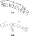
- the air diverter assembly 59 is illustrated in Figure 3A with baffle 76 and louver 70. As shown, a boss 74 on the louver 70 is secured to bolt holding tabs 78 on the baffle. Similarly, a post 80 on the louver is secured to a mating post on the baffle 76. There are ribs 72 on the baffle that serve to guide the airflow as explained above. The ribs 72 are spaced by a distance L.
- FIG. 3B shows detail of the louver 70 having the post 80 and its own ribs 82. Ribs 82 are spaced by a distance l.
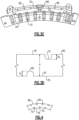
- Figure 3C is a view from the rear of the baffle plate 76 showing the ribs 72, which are also on the forward face as is clear from Figure 3A . However, one can also see that the louver 70 has ribs 82 facing the ribs 72 on the baffle plate 76. As shown, a height or distance of the airflow channel between an inner face of the louver 70 and the opposed face of the baffle 76 is defined as H.
- the ribs 82 on the louver 70 extend away from a nominal face 91 by a distance lh.
- the distance H is also illustrated here.
- the ribs 72 on the baffle 76 extend away from the nominal face 90 by a distance of Bh.
- a ratio of Bh/H is greater than or equal to 0.1 and less than or equal to 0.75 in the embodiments.
- the ratio of lh/H is greater than or equal to 0.01 and less than or equal to 0.5.
- the distances L and l are defined as shown in Figure 4 to achieve a staggered or circumferentially offset relationship between the ribs 82 and 72. That is, as illustrated, the ribs 72 are circumferentially offset from the ribs 82.
- the spacing Land l may be equal, or l may be greater than L, or L may be greater than 1. In the end, it is desired to achieve the staggered relationship.
- Ribs serve to direct and control airflow while also absorbing and distributing vibratory forces.
- the ribs effectively mitigate stress that is driven by airflow.
- the prior art has sometimes used ribs on the baffle, but there have not been staggered ribs on the two parts.
- ribs are shown as a particular shape, other shapes such as elliptical, rectangular, triangular may be utilized.
- a gas turbine engine under this disclosure could be said to include a fan 22 operable for delivering air into a bypass duct B.
- the fan is also operable for delivering air into a core engine housing 62.
- the core engine housing encloses a compressor 24, a combustor 34 and a turbine section 36.
- the core engine housing has an upstream end defining a separation point between the bypass duct and the core engine housing.
- An air separation device 59 is adjacent the upstream end.
- the air separation device includes a baffle 76 and an opposed louver 70.
- the baffle 76 and louver 70 together are structured for defining an airflow path to guide air adjacent the upstream end with a radially outward and axially downstream components.
- the baffle ribs 72 extend radially inward of the louver such that some airflow will initially encounter the baffle 70, and the ribs 72 for guiding the air into a flow channel defined between the baffle and the louver. The air will begin to encounter/interface the louver ribs and baffle ribs.
- the louver is fixed to the baffle.
- a passage height H of the flow channel between the louver and the baffle at a maximum distance is defined.
- louver rib height lh of the louver ribs extending away from a nominal face and a ratio of the louver rib height to the passage height H being greater than or equal to 0.01 and less than or equal to 0.5.
- baffle rib distance L circumferentially between circumferentially adjacent baffle ribs and there is a louver rib distance i between circumferentially adjacent louver ribs and the baffle rib distance is equal to the louver rib distance.
- baffle rib distance L circumferentially between circumferentially baffle ribs on the baffle and there is a louver rib distance l between circumferentially adjacent louver ribs on the louver and the baffle rib distance being greater than the louver rib distance.
- baffle rib there is a baffle rib distance circumferentially between circumferentially adjacent baffle ribs on the baffle and there is a louver rib distance between circumferentially adjacent louver ribs on the louver and the louver rib distance being greater than the baffle rib distance.
- the louver is fixed to the baffle.
- a passage height of a flow channel between the louver and the baffle at its maximum distance is defined.
- louver rib height of the louver ribs extending away from a nominal face of the louver and a ratio of the louver ribs height to the passage height being greater than or equal to 0.01 and less than or equal to 0.5.
- baffle rib there is a baffle rib distance circumferentially between circumferentially adjacent baffle ribs one the baffle and there is a louver rib distance between circumferentially adjacent louver ribs on the louver and the baffle rib distance being equal to the louver rib distance.
- baffle rib distance circumferentially between circumferentially baffle ribs on the baffle and there is a louver rib distance between circumferentially adjacent ribs on the louver and the baffle rib distance being greater than the louver rib distance.
- baffle rib there is a baffle rib distance circumferentially between circumferentially adjacent baffle ribs on the baffle and there is a louver rib distance between circumferentially adjacent louver ribs on the louver and the louver rib distance being greater than the baffle rib distance.
- a passage height of a flow channel between the louver and the baffle at a maximum distance is defined.
- louver rib height of the louver ribs extending away from a nominal face and a ratio of the louver ribs height to the passage height being greater than or equal to 0.01 and less than or equal to 0.5.
- baffle rib distance circumferentially between circumferentially adjacent baffle ribs and there is a louver rib distance between circumferentially adjacent louver ribs and the baffle rib distance being equal to the louver rib distance.
- baffle rib distance circumferentially between circumferentially baffle ribs and there is a louver rib distance between circumferentially adjacent louver ribs and the baffle rib distance being greater than the louver rib distance.
- baffle rib there is a baffle rib distance circumferentially between circumferentially adjacent baffle ribs and there is a louver rib distance between circumferentially adjacent louver ribs and the louver rib distance being greater than the baffle rib distance.
Landscapes
- Engineering & Computer Science (AREA)
- Chemical & Material Sciences (AREA)
- Combustion & Propulsion (AREA)
- Mechanical Engineering (AREA)
- General Engineering & Computer Science (AREA)
- Physics & Mathematics (AREA)
- Fluid Mechanics (AREA)
- Structures Of Non-Positive Displacement Pumps (AREA)
Abstract
Description
- The invention relates to a flow diverting louver and baffle with ribs for use in a gas turbine engine.
- Gas turbine engines are known, and typically include a propulsor delivering air into a bypass duct, and into a core engine. The air in the core engine is compressed in a compressor, and delivered into a combustor. Fuel is mixed with the compressed air and it is ignited. Products of the combustion pass downstream over turbine rotors, driving them to rotate. The turbine motors in turn rotate the compressor and propulsor rotor.
- The core engine is within a core engine housing. A splitter of the core engine housing is at the upstream end of the core engine, and serves to split the bypass duct from the core engine. There is an air diverter at the upstream end of the core housing, and having a louver and baffle. The purpose of the louver and baffle is to divert the air from the splitter radially outwardly and with an axially downstream component into the bypass duct flow.
- In an aspect of the invention a gas turbine engine is provided. The gas turbine engine comprises a fan operable to deliver air into a bypass duct and into a core engine housing. The core engine housing encloses a compressor, a combustor and a turbine (e.g. a turbine section). The core engine housing has an upstream end defining a separation point between the bypass duct and the core engine housing. An air separation device is provided adjacent the upstream end. The air separation device includes a baffle and a louver opposed to the baffle. The baffle and the louver together define an airflow path to guide air adj acent the upstream end. The airflow path includes a radially outward component and an axially downstream component (e.g., extending radially outwardly with an axially downstream component into the bypass duct flow). The baffle comprises baffle ribs facing opposed louver ribs on the louver. At least one (e.g., at least some) of the louver ribs is circumferentially offset from the baffle ribs.
- In any of the aspects or embodiments described above and herein, the baffle ribs may extend radially inward of the louver such that the airflow path initially encounters the baffle and the baffle ribs to guide the air into a flow channel defined between (e.g., radially and/or axially between) the baffle and the louver before the airflow path encounters the louver ribs.
- In any of the aspects or embodiments described above and herein, the louver may be fixed to the baffle.
- In any of the aspects or embodiments described above and herein, a passage height (e.g., a maximum passage height) of a or the flow channel may be defined between the louver and the baffle.
- In any of the aspects or embodiments described above and herein, the baffle ribs may extend away from a nominal face of the baffle (a baffle face opposed to the louver) by a baffle rib height. A ratio of the baffle rib height to the passage height may be greater than or equal to 0.1 and less than or equal to 0.75.
- In any of the aspects or embodiments described above and herein, the louver ribs may extend away from a nominal face of the louver (a louver face opposed to the baffle) by a louver rib height. A ratio of the louver rib height to the passage height may be greater than or equal to 0.01 and less than or equal to 0.5.
- In any of the aspects or embodiments described above and herein, the passage height may be defined between a or the nominal face of the louver and a or the nominal face of the baffle.
- In any of the aspects or embodiments described above and herein, a baffle rib distance between circumferentially adjacent baffle ribs may be equal to a louver rib distance between circumferentially adjacent louver ribs.
- In any of the aspects or embodiments described above and herein, a baffle rib distance between circumferentially baffle ribs may be greater than a louver rib distance between circumferentially adjacent louver ribs.
- In any of the aspects or embodiments described above and herein, a louver rib distance between circumferentially adjacent louver ribs may be greater than a baffle rib distance between circumferentially adjacent baffle ribs.
- These and other features will be best understood from the following drawings and specification, the following is a brief description.
-
-
Figure 1 schematically shows a gas turbine engine. -
Figure 2A is a front view looking into a gas turbine engine. -
Figure 2B schematically shows an air diverter associated with a gas turbine engine. -
Figure 3A shows a flow diverting baffle and louver combination. -
Figure 3B is a view of the louver. -
Figure 3C shows the assembled baffle and louver. -
Figure 3D schematically shows a feature relating to ribs on the baffle and louver. -
Figure 4 schematically shows another feature with regard to the ribs. -
Figure 1 schematically illustrates agas turbine engine 20. The examplegas turbine engine 20 is a turbofan that generally incorporates afan section 22, acompressor section 24, acombustor section 26 and aturbine section 28. Thefan section 22 drives air along a bypass flow path B in a bypass duct defined within anacelle 30. Theturbine engine 20 intakes air along a core flow path C into thecompressor section 24 for compression and communication into thecombustor section 26. In thecombustor section 26, the compressed air is mixed with fuel from afuel system 32 and ignited byigniter 34 to generate an exhaust gas flow that expands through theturbine section 28 and is exhausted throughexhaust nozzle 36. Although depicted as a turbofan turbine engine in the disclosed non-limiting embodiment, it should be understood that the concepts described herein are not limited to use with turbofans as the teachings may be applied to other types of turbine engines. As one example, rather than having the propulsor be an enclosed fan, the propulsor may be an open propeller. This embodiment can also be applied to industrial gas turbine engine as well. - An engine housing 62 upstream most end is known as a splitter. This separates the bypass duct from the core engine. As shown schematically, an
airflow diverter assembly 59 is at the upstream end. - The
airfoil diverter assembly 59 is better shown inFigure 2B . Anouter housing 61 surrounds theflow diverter assembly 59. - As shown, the flow diverter assembly includes a
baffle 76 and alouver 70. The baffle and louver are curved so as to guide air from thesplitter end 60 of thehousing 62 with a radially outward and axially downstream component. The air adjacent thesplitter 60 will initially encounter thebaffle 76 and be guided by ribs (disclosed below) radially outwardly and curving with a downstream axial component until it reaches thelouver 70. Ribs on thelouver 70 will assist in guiding the air in the desired direction such that it blends easily into the bypass airflow B. - The
air diverter assembly 59 is illustrated inFigure 3A withbaffle 76 andlouver 70. As shown, aboss 74 on thelouver 70 is secured tobolt holding tabs 78 on the baffle. Similarly, apost 80 on the louver is secured to a mating post on thebaffle 76. There areribs 72 on the baffle that serve to guide the airflow as explained above. Theribs 72 are spaced by a distance L. -
Figure 3B shows detail of thelouver 70 having thepost 80 and itsown ribs 82.Ribs 82 are spaced by a distance l. -
Figure 3C is a view from the rear of thebaffle plate 76 showing theribs 72, which are also on the forward face as is clear fromFigure 3A . However, one can also see that thelouver 70 hasribs 82 facing theribs 72 on thebaffle plate 76. As shown, a height or distance of the airflow channel between an inner face of thelouver 70 and the opposed face of thebaffle 76 is defined as H. - As shown in
Figure 3D , theribs 82 on thelouver 70 extend away from anominal face 91 by a distance lh. The distance H is also illustrated here. Theribs 72 on thebaffle 76 extend away from thenominal face 90 by a distance of Bh. - In embodiments a ratio of Bh/H is greater than or equal to 0.1 and less than or equal to 0.75 in the embodiments. The ratio of lh/H is greater than or equal to 0.01 and less than or equal to 0.5.
- The distances L and l are defined as shown in
Figure 4 to achieve a staggered or circumferentially offset relationship between theribs ribs 72 are circumferentially offset from theribs 82. The spacing Land l may be equal, or l may be greater than L, or L may be greater than 1. In the end, it is desired to achieve the staggered relationship. - Applicant has found that this staggered relationship provides several benefits.
- Ribs serve to direct and control airflow while also absorbing and distributing vibratory forces. The ribs effectively mitigate stress that is driven by airflow. By having the staggered ribs along the length of the baffle and louver, superior control of the airflow and vibratory stress reduction are achieved. The prior art has sometimes used ribs on the baffle, but there have not been staggered ribs on the two parts.
- While the ribs are shown as a particular shape, other shapes such as elliptical, rectangular, triangular may be utilized.
- A gas turbine engine under this disclosure could be said to include a
fan 22 operable for delivering air into a bypass duct B. The fan is also operable for delivering air into acore engine housing 62. The core engine housing encloses acompressor 24, acombustor 34 and aturbine section 36. The core engine housing has an upstream end defining a separation point between the bypass duct and the core engine housing. Anair separation device 59 is adjacent the upstream end. The air separation device includes abaffle 76 and anopposed louver 70. Thebaffle 76 andlouver 70 together are structured for defining an airflow path to guide air adjacent the upstream end with a radially outward and axially downstream components. There arebaffle ribs 72 on thebaffle 76 facing opposedlouver ribs 82 on thelouver 70, with at least some of thelouver ribs 82 being circumferentially offset from thebaffle ribs 72. - In another embodiment according to the previous embodiment, the
baffle ribs 72 extend radially inward of the louver such that some airflow will initially encounter thebaffle 70, and theribs 72 for guiding the air into a flow channel defined between the baffle and the louver. The air will begin to encounter/interface the louver ribs and baffle ribs. - In another embodiment according to any of the previous embodiments, the louver is fixed to the baffle.
- In another embodiment according to any of the previous embodiments, a passage height H of the flow channel between the louver and the baffle at a maximum distance is defined. There is a baffle rib height Bh of the baffle ribs on the baffle extending away from a nominal face of the baffle, with a ratio of the baffle rib height to the passage height being greater than or equal to 0.1 and less than or equal to 0.75.
- In another embodiment according to any of the previous embodiments, there is a louver rib height lh of the louver ribs extending away from a nominal face and a ratio of the louver rib height to the passage height H being greater than or equal to 0.01 and less than or equal to 0.5.
- In another embodiment according to any of the previous embodiments, there is a baffle rib distance L circumferentially between circumferentially adjacent baffle ribs and there is a louver rib distance i between circumferentially adjacent louver ribs and the baffle rib distance is equal to the louver rib distance.
- In another embodiment according to any of the previous embodiments, there is a baffle rib distance L circumferentially between circumferentially baffle ribs on the baffle and there is a louver rib distance l between circumferentially adjacent louver ribs on the louver and the baffle rib distance being greater than the louver rib distance.
- In another embodiment according to any of the previous embodiments, there is a baffle rib distance circumferentially between circumferentially adjacent baffle ribs on the baffle and there is a louver rib distance between circumferentially adjacent louver ribs on the louver and the louver rib distance being greater than the baffle rib distance.
- In another embodiment according to any of the previous embodiments, the louver is fixed to the baffle.
- In another embodiment according to any of the previous embodiments, a passage height of a flow channel between the louver and the baffle at its maximum distance is defined. There is a baffle rib height of the baffle ribs on the baffle extending away from a nominal face of the baffle, with a ratio of the baffle rib height to the passage height being greater than or equal to 0.1 and less than or equal to 0.75.
- In another embodiment according to any of the previous embodiments, there is a louver rib height of the louver ribs extending away from a nominal face of the louver and a ratio of the louver ribs height to the passage height being greater than or equal to 0.01 and less than or equal to 0.5.
- In another embodiment according to any of the previous embodiments, there is a baffle rib distance circumferentially between circumferentially adjacent baffle ribs one the baffle and there is a louver rib distance between circumferentially adjacent louver ribs on the louver and the baffle rib distance being equal to the louver rib distance.
- In another embodiment according to any of the previous embodiments, there is a baffle rib distance circumferentially between circumferentially baffle ribs on the baffle and there is a louver rib distance between circumferentially adjacent ribs on the louver and the baffle rib distance being greater than the louver rib distance.
- In another embodiment according to any of the previous embodiments, there is a baffle rib distance circumferentially between circumferentially adjacent baffle ribs on the baffle and there is a louver rib distance between circumferentially adjacent louver ribs on the louver and the louver rib distance being greater than the baffle rib distance.
- In another embodiment according to any of the previous embodiments, a passage height of a flow channel between the louver and the baffle at a maximum distance is defined. There is a baffle rib height of the baffle ribs on the baffle extending away from a nominal face of the baffle, with a ratio of the baffle rib height to the passage height being greater than or equal to 0.1 and less than or equal to 0.75.
- In another embodiment according to any of the previous embodiments, there is a louver rib height of the louver ribs extending away from a nominal face and a ratio of the louver ribs height to the passage height being greater than or equal to 0.01 and less than or equal to 0.5.
- In another embodiment according to any of the previous embodiments, there is a passage height of a flow channel between the louver and the baffle at a maximum distance a louver rib height of the louver ribs extending away from a nominal face of the louver and a ratio of the louver ribs height to the passage height being greater than or equal to 0.01 and less than or equal to 0.5.
- In another embodiment according to any of the previous embodiments, there is a baffle rib distance circumferentially between circumferentially adjacent baffle ribs and there is a louver rib distance between circumferentially adjacent louver ribs and the baffle rib distance being equal to the louver rib distance.
- In another embodiment according to any of the previous embodiments, there is a baffle rib distance circumferentially between circumferentially baffle ribs and there is a louver rib distance between circumferentially adjacent louver ribs and the baffle rib distance being greater than the louver rib distance.
- In another embodiment according to any of the previous embodiments, there is a baffle rib distance circumferentially between circumferentially adjacent baffle ribs and there is a louver rib distance between circumferentially adjacent louver ribs and the louver rib distance being greater than the baffle rib distance.
- Although embodiments have been disclosed, a worker of skill in this art would recognize that modifications would come within the scope of this disclosure. For that reason, the following claims should be studied to determine the true scope and content.
Claims (10)
- A gas turbine engine (20) comprising:a fan (22) operable to deliver air into a bypass duct and into a core engine housing (62), the core engine housing (62) enclosing a compressor (24), a combustor (34) and a turbine (28), and the core engine housing (62) having an upstream end (60) defining a separation point between the bypass duct and the core engine housing (62); andan air separation device (59) adjacent the upstream end (60), the air separation device (59) including a baffle (76) and a louver (70) opposed to the baffle (76), wherein:the baffle (76) and the louver (70) together define an airflow path to guide air adjacent the upstream end (60), the airflow path including a radially outward component and an axially downstream component; andthe baffle (76) comprises baffle ribs (72) facing opposed louver ribs (82) on the louver (70), with at least one of the louver ribs (82) being circumferentially offset from the baffle ribs (72).
- The gas turbine engine (20) as set forth in claim 1, wherein the baffle ribs (72) extend radially inward of the louver (70) such that the airflow path initially encounters the baffle (76) and the baffle ribs (72) to guide the air into a flow channel defined between the baffle (76) and the louver (70) before the airflow path encounters the louver ribs (82).
- The gas turbine engine (20) as set forth in claim 1 or 2, wherein the louver (70) is fixed to the baffle (76).
- The gas turbine engine (20) as set forth in claim 1, 2 or 3, wherein a passage height (H) of a or the flow channel is defined between the louver (70) and the baffle (76).
- The gas turbine engine (20) as set forth in claim 4, wherein the baffle ribs (72) extend away from a nominal face (90) of the baffle (76) by a baffle rib height (Bh) and a ratio of the baffle rib height (Bh) to the passage height (H) is greater than or equal to 0.1 and less than or equal to 0.75.
- The gas turbine engine (20) as set forth in claim 4 or 5, wherein the louver ribs (82) extend away from a nominal face (91) of the louver (70) by a louver rib height (lh) and a ratio of the louver rib height (lh) to the passage height (H) is greater than or equal to 0.01 and less than or equal to 0.5.
- The gas turbine engine (20) as set forth in claim 4, 5 or 6, wherein the passage height (H) is defined between a or the nominal face (91) of the louver (70) and a or the nominal face (90) of the baffle (76).
- The gas turbine engine (20) as set forth in any preceding claim, wherein a baffle rib distance (L) between circumferentially adjacent baffle ribs (72) is equal to a louver rib distance (l) between circumferentially adjacent louver ribs (82).
- The gas turbine engine (20) as set forth in any of claims 1 to 7, wherein a baffle rib distance (L) between circumferentially baffle ribs (72) is greater than a louver rib distance (l) between circumferentially adjacent louver ribs (82).
- The gas turbine engine (20) as set forth in any of claims 1 to 7, wherein a louver rib distance (l) between circumferentially adjacent louver ribs (82) is greater than a baffle rib distance (L) between circumferentially adjacent baffle ribs (72).
Applications Claiming Priority (1)
| Application Number | Priority Date | Filing Date | Title |
|---|---|---|---|
| US18/239,320 US12326112B2 (en) | 2023-08-29 | 2023-08-29 | Gas turbine engine bypass louver and baffle rib design |
Publications (1)
| Publication Number | Publication Date |
|---|---|
| EP4517071A1 true EP4517071A1 (en) | 2025-03-05 |
Family
ID=92627106
Family Applications (1)
| Application Number | Title | Priority Date | Filing Date |
|---|---|---|---|
| EP24197382.5A Pending EP4517071A1 (en) | 2023-08-29 | 2024-08-29 | Gas turbine engine bypass louver and baffle rib design |
Country Status (3)
| Country | Link |
|---|---|
| US (1) | US12326112B2 (en) |
| EP (1) | EP4517071A1 (en) |
| CA (1) | CA3250579A1 (en) |
Citations (4)
| Publication number | Priority date | Publication date | Assignee | Title |
|---|---|---|---|---|
| US20100180573A1 (en) * | 2009-01-21 | 2010-07-22 | Rolls-Royce Plc | A gas turbine engine |
| US10280872B2 (en) * | 2015-08-27 | 2019-05-07 | Rolls-Royce North American Technologies Inc. | System and method for a fluidic barrier from the upstream splitter |
| EP4043715A2 (en) * | 2021-02-16 | 2022-08-17 | Pratt & Whitney Canada Corp. | Fluid cooler installation and method for turbofan engine |
| US20230073647A1 (en) * | 2021-09-09 | 2023-03-09 | General Electric Company | Compressor bleed for gas turbine engine |
Family Cites Families (7)
| Publication number | Priority date | Publication date | Assignee | Title |
|---|---|---|---|---|
| US5809772A (en) * | 1996-03-29 | 1998-09-22 | General Electric Company | Turbofan engine with a core driven supercharged bypass duct |
| US6438941B1 (en) * | 2001-04-26 | 2002-08-27 | General Electric Company | Bifurcated splitter for variable bleed flow |
| WO2006091138A1 (en) * | 2005-02-25 | 2006-08-31 | Volvo Aero Corporation | A bleed structure for a bleed passage in a gas turbine engine |
| EP2075194B1 (en) * | 2007-12-27 | 2017-08-16 | Techspace Aero | Air-oil heat exchanger for a turbojet, corresponding turbojet and use of said heat exchanger |
| US10823055B2 (en) | 2016-08-08 | 2020-11-03 | Pratt & Whitney Canada Corp. | Bypass duct louver for noise mitigation |
| GB201903465D0 (en) | 2019-03-14 | 2019-05-01 | Rolls Royce Plc | Louvre system |
| US11702995B2 (en) | 2020-07-15 | 2023-07-18 | Pratt & Whitney Canada Corp. | Devices and methods for guiding bleed air in a turbofan engine |
-
2023
- 2023-08-29 US US18/239,320 patent/US12326112B2/en active Active
-
2024
- 2024-07-31 CA CA3250579A patent/CA3250579A1/en active Pending
- 2024-08-29 EP EP24197382.5A patent/EP4517071A1/en active Pending
Patent Citations (4)
| Publication number | Priority date | Publication date | Assignee | Title |
|---|---|---|---|---|
| US20100180573A1 (en) * | 2009-01-21 | 2010-07-22 | Rolls-Royce Plc | A gas turbine engine |
| US10280872B2 (en) * | 2015-08-27 | 2019-05-07 | Rolls-Royce North American Technologies Inc. | System and method for a fluidic barrier from the upstream splitter |
| EP4043715A2 (en) * | 2021-02-16 | 2022-08-17 | Pratt & Whitney Canada Corp. | Fluid cooler installation and method for turbofan engine |
| US20230073647A1 (en) * | 2021-09-09 | 2023-03-09 | General Electric Company | Compressor bleed for gas turbine engine |
Also Published As
| Publication number | Publication date |
|---|---|
| US12326112B2 (en) | 2025-06-10 |
| CA3250579A1 (en) | 2025-06-05 |
| US20250075657A1 (en) | 2025-03-06 |
Similar Documents
| Publication | Publication Date | Title |
|---|---|---|
| JP7011502B2 (en) | Centrifugal compressor pipe diffuser | |
| CN108930557B (en) | Method and system for auxiliary guide vanes at the leading edge of compressor guide vanes | |
| EP2812558B1 (en) | Gas turbine engine with separate core and propulsion unit | |
| EP2014901A2 (en) | Gas turbine engine with dual fans driven about a central core axis | |
| EP3284942B1 (en) | Direct drive aft fan engine | |
| US20030136102A1 (en) | Diffuser for terrestrial or aviation gas turbine | |
| EP3282117B1 (en) | Exhaust duct for turbine forward of fan | |
| EP3090126B1 (en) | Gas turbine engine component comprising endwall countouring trench | |
| EP3263867B1 (en) | Particle extraction system for a gas turbine engine | |
| EP3225818A1 (en) | Turbine engine designs for improved fine particle separation efficiency | |
| EP3036422B1 (en) | High performance convergent divergent nozzle | |
| CN108952823A (en) | Method and system for leading edge auxiliary blade | |
| EP3111057B1 (en) | Tie rod connection for mid-turbine frame | |
| EP3181824A1 (en) | Gas turbine engine with short inlet and mistuned fan blades | |
| EP2927433A1 (en) | Active clearance control for gas turbine engine | |
| EP3056685B1 (en) | Stator vane with platform having sloped face | |
| EP2587037A2 (en) | Turbofan engine mixer assembly | |
| CA3075160A1 (en) | Tandem stators with flow recirculation conduit | |
| CA2567940C (en) | Methods and apparatuses for gas turbine engines | |
| EP3159503A1 (en) | Compressor bleeding arrangement for a gas turbine and method of manufacturing a compressor section for a gas turbine | |
| EP3536902B1 (en) | Gas turbine engine component | |
| EP4624733A2 (en) | Open pusher rotor with remote exhaust | |
| US12326112B2 (en) | Gas turbine engine bypass louver and baffle rib design | |
| EP2904209B1 (en) | Bi-directional compression fan rotor for a gas turbine engine | |
| US11578654B2 (en) | Centrifical compressor assembly for a gas turbine engine |
Legal Events
| Date | Code | Title | Description |
|---|---|---|---|
| PUAI | Public reference made under article 153(3) epc to a published international application that has entered the european phase |
Free format text: ORIGINAL CODE: 0009012 |
|
| STAA | Information on the status of an ep patent application or granted ep patent |
Free format text: STATUS: THE APPLICATION HAS BEEN PUBLISHED |
|
| AK | Designated contracting states |
Kind code of ref document: A1 Designated state(s): AL AT BE BG CH CY CZ DE DK EE ES FI FR GB GR HR HU IE IS IT LI LT LU LV MC ME MK MT NL NO PL PT RO RS SE SI SK SM TR |
|
| STAA | Information on the status of an ep patent application or granted ep patent |
Free format text: STATUS: REQUEST FOR EXAMINATION WAS MADE |
|
| 17P | Request for examination filed |
Effective date: 20250905 |
|
| STAA | Information on the status of an ep patent application or granted ep patent |
Free format text: STATUS: EXAMINATION IS IN PROGRESS |
|
| RIC1 | Information provided on ipc code assigned before grant |
Ipc: F02C 7/04 20060101AFI20260106BHEP |
|
| 17Q | First examination report despatched |
Effective date: 20260115 |