EP4517070A1 - Heat exchanger bypass ejector - Google Patents
Heat exchanger bypass ejector Download PDFInfo
- Publication number
- EP4517070A1 EP4517070A1 EP24197058.1A EP24197058A EP4517070A1 EP 4517070 A1 EP4517070 A1 EP 4517070A1 EP 24197058 A EP24197058 A EP 24197058A EP 4517070 A1 EP4517070 A1 EP 4517070A1
- Authority
- EP
- European Patent Office
- Prior art keywords
- flow
- heat exchanger
- exhaust gas
- nozzle
- propulsion system
- Prior art date
- Legal status (The legal status is an assumption and is not a legal conclusion. Google has not performed a legal analysis and makes no representation as to the accuracy of the status listed.)
- Pending
Links
Images

Classifications
-
- F—MECHANICAL ENGINEERING; LIGHTING; HEATING; WEAPONS; BLASTING
- F02—COMBUSTION ENGINES; HOT-GAS OR COMBUSTION-PRODUCT ENGINE PLANTS
- F02C—GAS-TURBINE PLANTS; AIR INTAKES FOR JET-PROPULSION PLANTS; CONTROLLING FUEL SUPPLY IN AIR-BREATHING JET-PROPULSION PLANTS
- F02C6/00—Plural gas-turbine plants; Combinations of gas-turbine plants with other apparatus; Adaptations of gas-turbine plants for special use
- F02C6/04—Gas-turbine plants providing heated or pressurised working fluid for other apparatus, e.g. without mechanical power output
- F02C6/06—Gas-turbine plants providing heated or pressurised working fluid for other apparatus, e.g. without mechanical power output providing compressed gas
- F02C6/08—Gas-turbine plants providing heated or pressurised working fluid for other apparatus, e.g. without mechanical power output providing compressed gas the gas being bled from the gas-turbine compressor
-
- F—MECHANICAL ENGINEERING; LIGHTING; HEATING; WEAPONS; BLASTING
- F02—COMBUSTION ENGINES; HOT-GAS OR COMBUSTION-PRODUCT ENGINE PLANTS
- F02C—GAS-TURBINE PLANTS; AIR INTAKES FOR JET-PROPULSION PLANTS; CONTROLLING FUEL SUPPLY IN AIR-BREATHING JET-PROPULSION PLANTS
- F02C7/00—Features, components parts, details or accessories, not provided for in, or of interest apart form groups F02C1/00 - F02C6/00; Air intakes for jet-propulsion plants
- F02C7/12—Cooling of plants
- F02C7/14—Cooling of plants of fluids in the plant, e.g. lubricant or fuel
- F02C7/141—Cooling of plants of fluids in the plant, e.g. lubricant or fuel of working fluid
-
- F—MECHANICAL ENGINEERING; LIGHTING; HEATING; WEAPONS; BLASTING
- F02—COMBUSTION ENGINES; HOT-GAS OR COMBUSTION-PRODUCT ENGINE PLANTS
- F02C—GAS-TURBINE PLANTS; AIR INTAKES FOR JET-PROPULSION PLANTS; CONTROLLING FUEL SUPPLY IN AIR-BREATHING JET-PROPULSION PLANTS
- F02C3/00—Gas-turbine plants characterised by the use of combustion products as the working fluid
- F02C3/04—Gas-turbine plants characterised by the use of combustion products as the working fluid having a turbine driving a compressor
- F02C3/06—Gas-turbine plants characterised by the use of combustion products as the working fluid having a turbine driving a compressor the compressor comprising only axial stages
-
- F—MECHANICAL ENGINEERING; LIGHTING; HEATING; WEAPONS; BLASTING
- F02—COMBUSTION ENGINES; HOT-GAS OR COMBUSTION-PRODUCT ENGINE PLANTS
- F02C—GAS-TURBINE PLANTS; AIR INTAKES FOR JET-PROPULSION PLANTS; CONTROLLING FUEL SUPPLY IN AIR-BREATHING JET-PROPULSION PLANTS
- F02C6/00—Plural gas-turbine plants; Combinations of gas-turbine plants with other apparatus; Adaptations of gas-turbine plants for special use
- F02C6/20—Adaptations of gas-turbine plants for driving vehicles
- F02C6/206—Adaptations of gas-turbine plants for driving vehicles the vehicles being airscrew driven
-
- F—MECHANICAL ENGINEERING; LIGHTING; HEATING; WEAPONS; BLASTING
- F02—COMBUSTION ENGINES; HOT-GAS OR COMBUSTION-PRODUCT ENGINE PLANTS
- F02C—GAS-TURBINE PLANTS; AIR INTAKES FOR JET-PROPULSION PLANTS; CONTROLLING FUEL SUPPLY IN AIR-BREATHING JET-PROPULSION PLANTS
- F02C9/00—Controlling gas-turbine plants; Controlling fuel supply in air- breathing jet-propulsion plants
- F02C9/16—Control of working fluid flow
- F02C9/18—Control of working fluid flow by bleeding, bypassing or acting on variable working fluid interconnections between turbines or compressors or their stages
-
- F—MECHANICAL ENGINEERING; LIGHTING; HEATING; WEAPONS; BLASTING
- F02—COMBUSTION ENGINES; HOT-GAS OR COMBUSTION-PRODUCT ENGINE PLANTS
- F02C—GAS-TURBINE PLANTS; AIR INTAKES FOR JET-PROPULSION PLANTS; CONTROLLING FUEL SUPPLY IN AIR-BREATHING JET-PROPULSION PLANTS
- F02C7/00—Features, components parts, details or accessories, not provided for in, or of interest apart form groups F02C1/00 - F02C6/00; Air intakes for jet-propulsion plants
- F02C7/32—Arrangement, mounting, or driving, of auxiliaries
-
- F—MECHANICAL ENGINEERING; LIGHTING; HEATING; WEAPONS; BLASTING
- F05—INDEXING SCHEMES RELATING TO ENGINES OR PUMPS IN VARIOUS SUBCLASSES OF CLASSES F01-F04
- F05D—INDEXING SCHEME FOR ASPECTS RELATING TO NON-POSITIVE-DISPLACEMENT MACHINES OR ENGINES, GAS-TURBINES OR JET-PROPULSION PLANTS
- F05D2220/00—Application
- F05D2220/60—Application making use of surplus or waste energy
- F05D2220/62—Application making use of surplus or waste energy with energy recovery turbines
-
- F—MECHANICAL ENGINEERING; LIGHTING; HEATING; WEAPONS; BLASTING
- F05—INDEXING SCHEMES RELATING TO ENGINES OR PUMPS IN VARIOUS SUBCLASSES OF CLASSES F01-F04
- F05D—INDEXING SCHEME FOR ASPECTS RELATING TO NON-POSITIVE-DISPLACEMENT MACHINES OR ENGINES, GAS-TURBINES OR JET-PROPULSION PLANTS
- F05D2220/00—Application
- F05D2220/70—Application in combination with
- F05D2220/72—Application in combination with a steam turbine
-
- F—MECHANICAL ENGINEERING; LIGHTING; HEATING; WEAPONS; BLASTING
- F05—INDEXING SCHEMES RELATING TO ENGINES OR PUMPS IN VARIOUS SUBCLASSES OF CLASSES F01-F04
- F05D—INDEXING SCHEME FOR ASPECTS RELATING TO NON-POSITIVE-DISPLACEMENT MACHINES OR ENGINES, GAS-TURBINES OR JET-PROPULSION PLANTS
- F05D2260/00—Function
- F05D2260/20—Heat transfer, e.g. cooling
- F05D2260/213—Heat transfer, e.g. cooling by the provision of a heat exchanger within the cooling circuit
-
- F—MECHANICAL ENGINEERING; LIGHTING; HEATING; WEAPONS; BLASTING
- F05—INDEXING SCHEMES RELATING TO ENGINES OR PUMPS IN VARIOUS SUBCLASSES OF CLASSES F01-F04
- F05D—INDEXING SCHEME FOR ASPECTS RELATING TO NON-POSITIVE-DISPLACEMENT MACHINES OR ENGINES, GAS-TURBINES OR JET-PROPULSION PLANTS
- F05D2260/00—Function
- F05D2260/60—Fluid transfer
- F05D2260/601—Fluid transfer using an ejector or a jet pump
Definitions
- Turbine engines compress incoming core airflow, mix the compressed airflow with fuel that is ignited in a combustor to generate an exhaust gas flow.
- Improvements to conventional turbine engine architectures may include heat exchangers disposed in a core flow path. Heat exchangers impact exhaust gas flows, which generate a portion of engine thrust. Heat exchangers are a necessary component for improvements to engine architectures but present challenges to realization of improved engine efficiencies.
- the bottom cycle includes a recuperator heat exchanger where the first heat transfer medium is in thermal communication with a second heat transfer medium that is exhausted from the compressor and a cold sink heat exchanger where the second heat transfer medium is cooled by communication with a cold sink.
- an area ratio between an inlet throat area and a nozzle throat area of the ejector is between 10.0 and 9.0.
- a method of operating a gas turbine engine includes, among other possible things, generating an exhaust gas flow by igniting a mixture of compressed inlet air and fuel, communicating a first portion of the exhaust gas flow through a heat exchanger for communicating thermal energy into another flow, bypassing a second portion of the exhaust gas flow around the heat exchanger, increasing a pressure of an exit flow from the heat exchanger with a motive flow in an ejector, and communicating an outlet flow from the ejector and the second portion through an exhaust nozzle.
- the outlet flow may match a pressure of the second portion of the exhaust gas flow.
- the method further includes recovering a portion of thermal energy from the exhaust gas flow with a bottoming cycle by transferring thermal energy to a first heat transfer medium within the heat exchanger.
- the method further includes tapping the motive flow from a compressor section of the gas turbine engine.
- Figure 1 schematically illustrates an example propulsion system 20 that includes an ejector placed between a heat exchanger an exhaust nozzle to pressurize exit flow from the heat exchanger to a desired nozzle pressure. Only a portion of exhaust gas flow is communicated through the heat exchanger. The ejector increases the pressure of the exit flow to substantially match exhaust gas flow bypassed around the heat exchanger.
- the example propulsion system 20 includes a fan section 24 and a core engine 22.
- the core engine 22 includes a compressor section 26, a combustor section 28 and the turbine section 30 disposed along an engine longitudinal axis A.
- the fan section 24 drives inlet airflow along a bypass flow path B, while the compressor section 26 draws air in along a core flow path C.
- the inlet airflow is compressed and communicated to the combustor section 28 where the compressed core airflow is mixed with a fuel flow 36 and ignited to generate the exhaust gas flow 48.
- the exhaust gas flow 48 expands through the turbine section 30 where energy is extracted and utilized to drive the fan section 24 and the compressor section 26.
- the example core engine 22 includes a low pressure compressor 38 coupled to a low pressure turbine 44 and a high pressure compressor 40 coupled to be driven by a high pressure turbine 42.
- the fan 24 is driven by the low pressure turbine 44 through a gear system 32.
- the example gear system 32 provides a speed reduction so that both the fan 24 and the low pressure turbine 44 may operate at or near respective optimum speeds.
- a fuel system 34 provides a fuel flow 36 to the combustor 28.
- the example fuel system 34 may provide a hydrogen based fuel such as a liquid hydrogen (LH 2 ).
- a hydrogen based fuel such as a liquid hydrogen (LH 2 ).
- LH 2 liquid hydrogen
- hydrogen is disclosed as one example embodiment, other non-carbon based fuels could be utilized and are within the contemplation of this disclosure.
- the disclosed features may also be beneficial in an engine configured to operate with traditional carbon fuels and/or biofuels, such as sustainable aviation fuel.
- the exhaust gas flow 48 is split into a first flow portion 58 that is communicated through a heat exchanger 46 and a second flow portion 60 that is bypassed around the heat exchanger 46 and communicated directly to an exhaust nozzle 56.
- the heat exchanger 46 provides for the transfer of thermal energy from the first portion of the exhaust gas flow 58 into another fluid flow to recover and utilize thermal energy to improve engine efficiency.
- the heat exchanger 46 heats a first heat transfer medium 66 utilized by a bottoming cycle 64.
- the heat exchanger 46 may be part of other systems that utilize thermal energy to improve engine efficiency.
- the heat exchanger 46 may be part of an evaporator or condenser for a water recovery and steam generation system that recovers water from the exhaust gas flow 48 and uses heat to generate steam for injection into the core flow.
- other systems that utilize and recover thermal energy from the exhaust gas flow 48 with a heat exchanger are within the contemplation and scope of this disclosure.
- the first flow portion 58 of the exhaust gas flow 48 through the heat exchanger 46 experiences a drop in pressure.
- An exit flow 50 exiting the heat exchanger 46 is of a lower pressure than the first flow portion 58 and the second flow portion 60.
- the pressure drop across the heat exchanger 46 removes energy from the exhaust gas flow 48 that is utilized to generate propulsive thrust flow 84 through the nozzle 56.
- the pressure drop through the heat exchanger 46 creates an imbalance in gas flow pressures communicated to the nozzle 56 that reduces overall propulsive efficiency.
- the first flow portion 58 is less than half that of the second flow portion 60. In another disclosed example, the first flow portion 58 is less than about 25% of the total exhaust gas flow 48. In another example embodiment, the second flow portion is between 10% and 35% of the total exhaust flow 48.
- the example system 20 compensates for pressure drops through the heat exchanger 46 by increasing a pressure of the exit flow 50 with an ejector 52.
- the ejector 52 receives a motive flow 54 from a higher pressure location within the core engine 22 to draw the exit flow 50 from the heat exchanger 46.
- the exit flow 50 is mixed with the motive flow 54 to generate an increased pressure outlet flow 62 that closely matches the second flow portion 60 that is bypassed around the heat exchanger 46.
- a single ejector 52 is illustrated by way of example, however, several ejectors 52 may be utilized to tailor operation to different (e.g., application specific) configurations and provide the increased pressures of the outlet flow 62 to the nozzle.
- the motive flow 54 is drawn from a location 86 within the low pressure compressor 38. In another example embodiment, the motive flow 54 is drawn from a location 88 within the high pressure compressor 40.
- the motive flow 54 may be drawn from any location along the core flow path C that provides a desired flow and pressure determined to draw in the exit flow 50 and to generate the desired outlet flow 62.
- an actuator system 90 may be provided to vary the location from which the motive flow 54 is drawn based on current engine operating conditions. For example, the motive flow is taken from the location 86 based on a first operating condition and taken from second location 88 based on a second operation condition. In another disclosed example, the motive flow may be taken from a combination of the first location 86 and the second location 88 based on a third operating condition.
- the actuator system 90 may be a single valve or a system of many valves that are operated by the controller 92 to provide the motive flow 54 applicable to current engine operating conditions.
- the example controller 92 is a device and system for performing necessary computing or calculation operations of the actuator system 90.
- the controller 92 may be specially constructed for operation of the actuator system 90, or it may comprise at least a general-purpose computer selectively activated or reconfigured by software instructions stored in a memory device.
- the controller 92 may further be part of a full authority digital engine control (FADEC) or an electronic engine controller (EEC).
- FADEC full authority digital engine control
- EEC electronic engine controller
- the example heat exchanger 46 transfers thermal energy from the exhaust gas flow 48 to the bottoming cycle 64.
- the example bottoming cycle 64 includes a first heat transfer medium 66 that accepts heat from the first flow portion 58.
- the first heat transfer medium 66 is heated and expanded through a turbine 70 that is coupled to drive a compressor 72 through a gearbox 74.
- the turbine 70 may drive an output shaft 94 to drive an accessory component or device that is schematically indicated at 96.
- the accessory component 96 may include a pump, generator, actuator, or any other aircraft accessory device.
- the example bottoming cycle 64 includes a second heat transfer medium, shown schematically at 68 that is pressurized by the compressor 72 and heated in a recuperation heat exchanger 76 by the first heat transfer medium 66.
- the second heat transfer medium 68 may be further cooled in a cold sink heat exchanger 78 and recycled through the compressor 72.
- the propulsion system 120 includes a booster compressor 80 that is driven by an electric motor 82.
- the motive flow 54 drawn from the locations 86 and 88 may not provide the pressures required to generate the desired outlet flow 62. Accordingly, the booster compressor 80 is operated to increase pressure of the motive flow 54.
- the example booster compressor 80 is driven by an electric motor 82 that is controlled by the controller 92.
- the booster compressor 80 provides for drawing of location within the compressor section 26 that may not be of sufficient pressure, but that have a lesser impact on engine operation.
- the booster compressor 80 provides for the use of a bleed airflow from other locations within the core flow path C.
Landscapes
- Engineering & Computer Science (AREA)
- Chemical & Material Sciences (AREA)
- Combustion & Propulsion (AREA)
- Mechanical Engineering (AREA)
- General Engineering & Computer Science (AREA)
- Physics & Mathematics (AREA)
- Fluid Mechanics (AREA)
- Jet Pumps And Other Pumps (AREA)
Abstract
An aircraft propulsion system (20) includes a core engine (22) for generating an exhaust gas flow (48) that is expanded through a turbine (42,44) to generate shaft power. A heat exchanger (46) is in communication with a first portion (58) of the exhaust gas flow (48) and an exit flow (50) is emitted from the heat exchanger (46). An ejector (52) is configured to increase a pressure of the exit flow (50) with a motive flow (54) taken from a core flow path (C).
Description
- The present invention relates generally to an aircraft propulsion system that includes an ejector for increasing flow pressures of exhaust flows exiting a heat exchanger.
- Reduction and/or elimination of carbon emissions generated by aircraft operation is a stated goal of aircraft manufacturers and airline operators. Turbine engines compress incoming core airflow, mix the compressed airflow with fuel that is ignited in a combustor to generate an exhaust gas flow. Improvements to conventional turbine engine architectures may include heat exchangers disposed in a core flow path. Heat exchangers impact exhaust gas flows, which generate a portion of engine thrust. Heat exchangers are a necessary component for improvements to engine architectures but present challenges to realization of improved engine efficiencies.
- An aircraft propulsion system according to an aspect of the present invention includes, among other possible things, a core engine where an inlet flow is communicated along a core flow path and is compressed, mixed with fuel, and ignited to generate an exhaust gas flow that is expanded through a turbine to generate shaft power. A heat exchanger is in communication with a first portion of the exhaust gas flow, an exit flow is emitted from the heat exchanger. A second portion of the exhaust gas flow is bypassed around the heat exchanger. An ejector is configured to increase a pressure of the exit flow from the heat exchanger with a motive flow taken from the core flow path. This may generate an emitted flow that matches the pressure of the second portion of the exhaust gas flow bypassed around the heat exchanger. A nozzle receives the second portion of the exhaust gas flow and the emitted exit flow from the ejector.
- Optionally, and in accordance with the above, the motive flow is taken from a compressor section within the core flow path.
- Optionally, and in accordance with any of the above, a location within the core flow path from which the motive flow is taken varies based on operating conditions.
- Optionally, and in accordance with any of the above, the motive flow is further pressurized by a booster compressor.
- Optionally, and in accordance with any of the above, the booster compressor is selectively driven by an electric motor.
- Optionally, and in accordance with any of the above, the aircraft propulsion system further includes a bottoming cycle that includes a first heat transfer medium that is in thermal communication with the partial portion of the exhaust gas flow within the heat exchanger.
- Optionally, and in accordance with any of the above, the bottoming cycle includes a turbine that is coupled to a compressor, and the first heat transfer medium expands through the turbine to drive the compressor.
- Optionally, and in accordance with any of the above, the bottom cycle includes a recuperator heat exchanger where the first heat transfer medium is in thermal communication with a second heat transfer medium that is exhausted from the compressor and a cold sink heat exchanger where the second heat transfer medium is cooled by communication with a cold sink.
- Optionally, and in accordance with any of the above, the ejector includes a motive flow nozzle configured to receive the motive flow, the motive flow nozzle including a nozzle inlet and a converging diverging nozzle, wherein the ejector includes an inlet throat area disposed around the converging diverging nozzle, the converging diverging nozzle includes a nozzle throat area, the motive flow nozzle includes an exit area. The inlet throat area may be defined as the cross-sectional area of the ejector around the converging diverging nozzle in a plane perpendicular to the longitudinal axis of the ejector at the axial location of an outlet of the converging diverging nozzle. The nozzle throat area may be defined as the cross-sectional area of the converging diverging nozzle in a plane perpendicular to the longitudinal axis of the converging diverging nozzle at the throat (i.e. the smallest cross-sectional area) of the converging diverging nozzle. The exit area may be defined as the cross-sectional area of the converging diverging nozzle in the plane perpendicular to the longitudinal axis of the converging diverging nozzle at an outlet of the converging diverging nozzle.
- Optionally, and in accordance with any of the above, an area ratio between an inlet throat area and a nozzle throat area of the ejector is between 10.0 and 9.0.
- Optionally, and in accordance with any of the above, an area ratio between an exit area and a throat area of a motive nozzle of the ejector is between 0.25 and 0.75.
- An aircraft propulsion system according to another aspect of the present invention includes, among other possible things, a propulsor for generating a propulsive thrust and a compressor section where an inlet airflow is compressed, the compressor section includes a low pressure compressor and a high pressure compressor, a combustor section where the compressed inlet airflow is mixed with fuel and ignited to generate an exhaust gas flow, a turbine section through which the exhaust gas flow expands to generate a mechanical power output for driving the propulsor and the compressor section, the turbine section includes a high pressure compressor and a low pressure compressor. A heat exchanger is in communication with a first portion of the exhaust gas flow, an exit flow is emitted from the heat exchanger. A second portion of the exhaust gas flow is bypassed around the heat exchanger. An ejector is configured to increase a pressure of the exit flow from the heat exchanger with a motive flow taken from the compressor section. This may generate an emitted flow that matches the pressure of the second portion of the exhaust gas flow bypassed around the heat exchanger. A nozzle receives the second portion of the exhaust gas flow and the emitted exit flow from the ejector.
- Optionally, and in accordance with any of the above, the motive flow is taken from a compressor section.
- Optionally, and in accordance with any of the above, a location within the compressor section from which the motive flow is taken varies based on operating conditions.
- Optionally, and in accordance with any of the above, the aircraft propulsion system includes an electrically driven booster compressor that further pressurizes the motive flow taken from the compressor section.
- Optionally, and in accordance with any of the above, the aircraft propulsion system further includes a bottoming cycle that includes a first heat transfer medium that is in thermal communication with the partial portion of the exhaust gas flow within the heat exchanger.
- Optionally, and in accordance with any of the above, an area ratio between an inlet throat area and a nozzle throat area of the ejector is between 10.0 and 9.0.
- Optionally, and in accordance with any of the above, the aircraft propulsion system includes a controller that is programed to operate a control device to vary the motive flow to the ejector based on engine operating conditions.
- A method of operating a gas turbine engine according to another aspect of the present invention includes, among other possible things, generating an exhaust gas flow by igniting a mixture of compressed inlet air and fuel, communicating a first portion of the exhaust gas flow through a heat exchanger for communicating thermal energy into another flow, bypassing a second portion of the exhaust gas flow around the heat exchanger, increasing a pressure of an exit flow from the heat exchanger with a motive flow in an ejector, and communicating an outlet flow from the ejector and the second portion through an exhaust nozzle. The outlet flow may match a pressure of the second portion of the exhaust gas flow.
- Optionally, and in accordance with any of the above, the method further includes recovering a portion of thermal energy from the exhaust gas flow with a bottoming cycle by transferring thermal energy to a first heat transfer medium within the heat exchanger.
- Optionally, and in accordance with any of the above, the method further includes tapping the motive flow from a compressor section of the gas turbine engine.
- Although the different examples have the specific components shown in the illustrations, embodiments of this invention are not limited to those particular combinations. It is possible to use some of the components or features from one of the examples in combination with features or components from another one of the examples.
- These and other features disclosed herein can be best understood from the following specification and drawings, the following of which is a brief description.
-
-
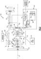
Figure 1 is a schematic view of an example aircraft propulsion system embodiment. -
Figure 2 is a schematic view of another example aircraft propulsion system embodiment. -
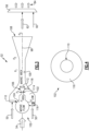
Figure 3 is a schematic view of an example ejector embodiment. -
Figure 4 is a schematic view of an inlet of the example ejector shown inFigure 3 . -
Figure 1 schematically illustrates anexample propulsion system 20 that includes an ejector placed between a heat exchanger an exhaust nozzle to pressurize exit flow from the heat exchanger to a desired nozzle pressure. Only a portion of exhaust gas flow is communicated through the heat exchanger. The ejector increases the pressure of the exit flow to substantially match exhaust gas flow bypassed around the heat exchanger. - The
example propulsion system 20 includes afan section 24 and acore engine 22. Thecore engine 22 includes acompressor section 26, acombustor section 28 and theturbine section 30 disposed along an engine longitudinal axis A. Thefan section 24 drives inlet airflow along a bypass flow path B, while thecompressor section 26 draws air in along a core flow path C. The inlet airflow is compressed and communicated to thecombustor section 28 where the compressed core airflow is mixed with afuel flow 36 and ignited to generate theexhaust gas flow 48. Theexhaust gas flow 48 expands through theturbine section 30 where energy is extracted and utilized to drive thefan section 24 and thecompressor section 26. - The
example core engine 22 includes alow pressure compressor 38 coupled to alow pressure turbine 44 and ahigh pressure compressor 40 coupled to be driven by ahigh pressure turbine 42. In one example embodiment, thefan 24 is driven by thelow pressure turbine 44 through agear system 32. Theexample gear system 32 provides a speed reduction so that both thefan 24 and thelow pressure turbine 44 may operate at or near respective optimum speeds. - Although an example engine architecture is disclosed by way of example, other turbine engine architectures are within the contemplation and scope of this disclosure. Moreover, although the disclosed non-limiting embodiment depicts a turbofan turbine engine, it should be understood that the concepts described herein are not limited to use with turbofans as the teachings may be applied to other types of turbine engines. Additionally, the features of this disclosure may be applied to other engine configurations utilized to generate shaft power.
- A
fuel system 34 provides afuel flow 36 to thecombustor 28. Theexample fuel system 34 may provide a hydrogen based fuel such as a liquid hydrogen (LH2). Although hydrogen is disclosed as one example embodiment, other non-carbon based fuels could be utilized and are within the contemplation of this disclosure. Moreover, the disclosed features may also be beneficial in an engine configured to operate with traditional carbon fuels and/or biofuels, such as sustainable aviation fuel. - The
exhaust gas flow 48 is split into afirst flow portion 58 that is communicated through aheat exchanger 46 and asecond flow portion 60 that is bypassed around theheat exchanger 46 and communicated directly to anexhaust nozzle 56. Theheat exchanger 46 provides for the transfer of thermal energy from the first portion of theexhaust gas flow 58 into another fluid flow to recover and utilize thermal energy to improve engine efficiency. In one disclosed example, theheat exchanger 46 heats a firstheat transfer medium 66 utilized by a bottomingcycle 64. - Although the bottoming
cycle 64 is disclosed by way of example, theheat exchanger 46 may be part of other systems that utilize thermal energy to improve engine efficiency. For example, theheat exchanger 46 may be part of an evaporator or condenser for a water recovery and steam generation system that recovers water from theexhaust gas flow 48 and uses heat to generate steam for injection into the core flow. Moreover, other systems that utilize and recover thermal energy from theexhaust gas flow 48 with a heat exchanger are within the contemplation and scope of this disclosure. - The
first flow portion 58 of theexhaust gas flow 48 through theheat exchanger 46 experiences a drop in pressure. Anexit flow 50 exiting theheat exchanger 46 is of a lower pressure than thefirst flow portion 58 and thesecond flow portion 60. The pressure drop across theheat exchanger 46 removes energy from theexhaust gas flow 48 that is utilized to generatepropulsive thrust flow 84 through thenozzle 56. Moreover, the pressure drop through theheat exchanger 46 creates an imbalance in gas flow pressures communicated to thenozzle 56 that reduces overall propulsive efficiency. - In one disclosed example, the
first flow portion 58 is less than half that of thesecond flow portion 60. In another disclosed example, thefirst flow portion 58 is less than about 25% of the totalexhaust gas flow 48. In another example embodiment, the second flow portion is between 10% and 35% of thetotal exhaust flow 48. - The
example system 20 compensates for pressure drops through theheat exchanger 46 by increasing a pressure of theexit flow 50 with anejector 52. Theejector 52 receives amotive flow 54 from a higher pressure location within thecore engine 22 to draw theexit flow 50 from theheat exchanger 46. Theexit flow 50 is mixed with themotive flow 54 to generate an increasedpressure outlet flow 62 that closely matches thesecond flow portion 60 that is bypassed around theheat exchanger 46. Asingle ejector 52 is illustrated by way of example, however,several ejectors 52 may be utilized to tailor operation to different (e.g., application specific) configurations and provide the increased pressures of theoutlet flow 62 to the nozzle. - In one example embodiment, the
motive flow 54 is drawn from alocation 86 within thelow pressure compressor 38. In another example embodiment, themotive flow 54 is drawn from alocation 88 within thehigh pressure compressor 40. Themotive flow 54 may be drawn from any location along the core flow path C that provides a desired flow and pressure determined to draw in theexit flow 50 and to generate the desiredoutlet flow 62. - Moreover, an
actuator system 90 may be provided to vary the location from which themotive flow 54 is drawn based on current engine operating conditions. For example, the motive flow is taken from thelocation 86 based on a first operating condition and taken fromsecond location 88 based on a second operation condition. In another disclosed example, the motive flow may be taken from a combination of thefirst location 86 and thesecond location 88 based on a third operating condition. - The
actuator system 90 may be a single valve or a system of many valves that are operated by thecontroller 92 to provide themotive flow 54 applicable to current engine operating conditions. - The
example controller 92 is a device and system for performing necessary computing or calculation operations of theactuator system 90. Thecontroller 92 may be specially constructed for operation of theactuator system 90, or it may comprise at least a general-purpose computer selectively activated or reconfigured by software instructions stored in a memory device. Thecontroller 92 may further be part of a full authority digital engine control (FADEC) or an electronic engine controller (EEC). - The
example heat exchanger 46 transfers thermal energy from theexhaust gas flow 48 to the bottomingcycle 64. Theexample bottoming cycle 64 includes a firstheat transfer medium 66 that accepts heat from thefirst flow portion 58. The firstheat transfer medium 66 is heated and expanded through aturbine 70 that is coupled to drive acompressor 72 through agearbox 74. Theturbine 70 may drive anoutput shaft 94 to drive an accessory component or device that is schematically indicated at 96. The accessory component 96 may include a pump, generator, actuator, or any other aircraft accessory device. - The
example bottoming cycle 64 includes a second heat transfer medium, shown schematically at 68 that is pressurized by thecompressor 72 and heated in arecuperation heat exchanger 76 by the firstheat transfer medium 66. The secondheat transfer medium 68 may be further cooled in a coldsink heat exchanger 78 and recycled through thecompressor 72. - Although an
example bottoming cycle 64 is shown and described by way of example, other systems that recover thermal energy from theexhaust gas flow 48 could be utilized and are within the contemplation and scope of this disclosure. - Referring to
Figure 2 , another example propulsion system is schematically shown and generally indicated at 120. Thepropulsion system 120 includes abooster compressor 80 that is driven by anelectric motor 82. Themotive flow 54 drawn from thelocations outlet flow 62. Accordingly, thebooster compressor 80 is operated to increase pressure of themotive flow 54. Theexample booster compressor 80 is driven by anelectric motor 82 that is controlled by thecontroller 92. Thebooster compressor 80 provides for drawing of location within thecompressor section 26 that may not be of sufficient pressure, but that have a lesser impact on engine operation. Thebooster compressor 80 provides for the use of a bleed airflow from other locations within the core flow path C. - Referring to
Figures 3 and 4 , with continued reference toFigures 1 and2 , theexample ejector 52 is schematically shown and draws in themotive flow 54 along alongitudinal axis 98. Theexample ejector 52 includes amotive flow nozzle 110 that receives themotive flow 54 and is disposed along theaxis 98. Themotive flow nozzle 110 includes anozzle inlet 104 and a converging divergingnozzle 106. The lowpressure exit flow 50 enters alow pressure inlet 102 that converges toward amixing area 100. In themixing area 100, themotive flow 54 and theexit flow 50 are mixed before being exhausted through a divergingexit opening 108. The higherpressure motive flow 54 creates a suction that draws theexit flow 50 into the mixingarea 100. - The
motive flow nozzle 110 receives themotive flow 54 at a high pressure (P high). Thelow pressure inlet 102 receives thelower exit flow 50 at a low pressure (P low). The velocity of themotive flow 54 increases through theflow nozzle 110 and is injected into the mixingarea 100. The pressure of themotive flow 54 changes to a throat area pressure (Pt) as velocity of the flow is increased. In themixing area 100, as the flows intermix and slow, pressure increases from a high velocity low pressure (P1) to a lower velocity higher pressure (P2). The final pressure (P3) of theoutlet flow 62 corresponds to the pressure of thesecond flow 60 that bypassed theheat exchanger 46. Theoutlet flow 62 andsecond flow 60 may not be identical, but are within a desired range that provides the desired flow through thenozzle 56 to generate the desiredpropulsive thrust flow 84. - The
example nozzle 106 is configured to accelerate themotive flow 54. In one example embodiment, thenozzle 106 includes a ratio of athroat area 114 to anexit area 112 that is between 0.35 and 0.75. - The
low pressure inlet 102 includes anannular inlet area 116 disposed about themotive flow nozzle 110 and aninlet throat area 118 that is disposed around thenozzle 106. In one example embodiment, a ratio of theinlet area 116 to theinlet throat area 118 is between 2.5 and 1.75. - In one example embodiment, an area ratio between the
inlet throat area 118 and thenozzle throat area 114 is between 10.0 and 9.0. - Although an example ejector embodiment is illustrated and disclosed by example, other ejector configurations with different area ratios could be utilized and are within the contemplation and scope of this disclosure.
- Accordingly, the example propulsion system embodiments accommodate pressure drops generated by heat exchangers within a partial portion of the exhaust gas flow by pressurizing exit flows with an ejector using motive flow drawn from high pressure locations within the core flow path.
- Although an example embodiment has been disclosed, a worker of ordinary skill in this art would recognize that certain modifications would come within the scope of this disclosure. For that reason, the following claims should be studied to determine the scope and content of this disclosure.
Claims (15)
- An aircraft propulsion system (20; 120) comprising:a core engine (22) in which an inlet flow is communicated along a core flow path (C) and is compressed, mixed with fuel, and ignited to generate an exhaust gas flow (48) that is expanded through a turbine (42,44) to generate shaft power;a heat exchanger (46) in communication with a first portion (58) of the exhaust gas flow (48), wherein the heat exchanger (46) is configured to emit an exit flow (50);an ejector (52) configured to increase a pressure of the exit flow (50) using a motive flow (54) taken from the core flow path (C); anda nozzle (56) configured to receive a second portion (60) of the exhaust gas flow (48) and an outlet flow (62) from the ejector (52).
- The aircraft propulsion system (20; 120) as recited in claim 1, wherein the motive flow (54) is taken from a compressor section (26) within the core flow path (C).
- The aircraft propulsion system (20; 120) as recited in claim 1 or 2, configured such that a location (86,88) within the core flow path (C) from which the motive flow (54) is taken is variable based on operating conditions.
- The aircraft propulsion system (120) as recited in claim 1, 2 or 3, wherein the motive flow (54) is further pressurized by a booster compressor (80), optionally wherein:
the booster compressor (80) is selectively driven by an electric motor (82). - The aircraft propulsion system (20; 120) as recited in any preceding claim, further comprising a bottoming cycle (64) that includes a first heat transfer medium (66) in thermal communication with the first portion (58) of the exhaust gas flow (48) within the heat exchanger (46).
- The aircraft propulsion system (20; 120) as recited in claim 5, wherein the bottoming cycle (64) comprises a turbine (70) coupled to a compressor (72), and the first heat transfer medium (66) expands through the turbine (70) to drive the compressor (72).
- The aircraft propulsion system (20;120) as recited in claim 6, wherein the bottoming cycle (64) includes a recuperator heat exchanger (76) in which the first heat transfer medium (66) is in thermal communication with a second heat transfer medium (68) exhausted from the compressor (72) and a cold sink heat exchanger (78) in which the second heat transfer medium (68) is cooled by communication with a cold sink.
- The aircraft propulsion system (20;120) as recited in any preceding claim, wherein the ejector (52) includes a motive flow nozzle (110) configured to receive the motive flow (54), the motive flow nozzle (110) including a nozzle inlet (104) and a converging diverging nozzle (106), wherein:the ejector (52) includes an inlet throat area (118) disposed around the converging diverging nozzle (106);the converging diverging nozzle (106) includes a nozzle throat area (114);the motive flow nozzle (110) includes an exit area (112).
- The aircraft propulsion system (20; 120) as recited in claim 8, wherein:an area ratio between the inlet throat area (118) and the nozzle throat area (114) is between 9.0 and 10.0; and/oran area ratio between the nozzle throat area (114) and the exit area (112) is between 0.25 and 0.75.
- The aircraft propulsion system (20; 120) of any preceding claim comprising:a propulsor (24) for generating a propulsive thrust;a compressor section (26) for compressing the inlet airflow, the compressor section (26) including a low pressure compressor (38) and a high pressure compressor (40);a combustor section (28) in which the compressed inlet airflow is mixed with fuel and ignited to generate the exhaust gas flow (48);a turbine section (30) through which the exhaust gas flow (48) expands to generate a mechanical power output for driving the propulsor (24) and the compressor section (26), wherein the turbine section (30) includes a high pressure turbine (42) and a low pressure turbine (44).
- The aircraft propulsion system (20;120) as recited in claim 10, wherein the motive flow (54) is taken from:a first location (86) based on a first operating condition; a second location (88) based on a second operation condition; and/ora combination of the first location (86) and the second location (88) based on a third operating condition.
- The aircraft propulsion system (20;120) as recited in claim 10 or 11, including a controller (92) programed to operate a control device (90) to vary the motive flow (54) to the ejector (52) based on engine operating conditions.
- A method of operating a gas turbine engine comprising:generating an exhaust gas flow (48) by igniting a mixture of compressed inlet air and fuel;communicating a first portion (58) of the exhaust gas flow (48) through a heat exchanger (46) for communicating thermal energy into another flow;bypassing a second portion (60) of the exhaust gas flow around the heat exchanger (46);increasing a pressure of an exit flow (50) from the heat exchanger (46) using a motive flow (54) in an ejector (52) to generate an outlet flow (62); andcommunicating the outlet flow (62) and the second portion (60) of the exhaust gas flow through an exhaust nozzle (56).
- The method as recited in claim 13, further comprising recovering a portion of thermal energy from the exhaust gas flow (48) with a bottoming cycle (64) by transferring thermal energy to a first heat transfer medium (66) within the heat exchanger (46).
- The method as recited in claim 13 or 14, further comprising tapping the motive flow (54) from a compressor section (26) of the gas turbine engine.
Applications Claiming Priority (1)
| Application Number | Priority Date | Filing Date | Title |
|---|---|---|---|
| US18/238,669 US12098676B1 (en) | 2023-08-28 | 2023-08-28 | Heat exchanger bypass ejector |
Publications (1)
| Publication Number | Publication Date |
|---|---|
| EP4517070A1 true EP4517070A1 (en) | 2025-03-05 |
Family
ID=92593314
Family Applications (1)
| Application Number | Title | Priority Date | Filing Date |
|---|---|---|---|
| EP24197058.1A Pending EP4517070A1 (en) | 2023-08-28 | 2024-08-28 | Heat exchanger bypass ejector |
Country Status (2)
| Country | Link |
|---|---|
| US (1) | US12098676B1 (en) |
| EP (1) | EP4517070A1 (en) |
Families Citing this family (2)
| Publication number | Priority date | Publication date | Assignee | Title |
|---|---|---|---|---|
| US20240083603A1 (en) * | 2023-11-17 | 2024-03-14 | Daniel Keith Schlak | Bladeless eVTOL Passenger Aircraft with Fixed-Wing Forward Flight Travel, and Method and Power Plant Therefor |
| US20250207529A1 (en) * | 2023-12-21 | 2025-06-26 | The Boeing Company | Non-recuperated supercritical carbon-dioxide brayton cycle heating for liquid natural gas-powered engines |
Citations (2)
| Publication number | Priority date | Publication date | Assignee | Title |
|---|---|---|---|---|
| EP1243757A1 (en) * | 1997-07-25 | 2002-09-25 | Alstom | Process for operating a power plant |
| JP2013148082A (en) * | 2011-12-21 | 2013-08-01 | Japan Aerospace Exploration Agency | Gas turbine device |
Family Cites Families (8)
| Publication number | Priority date | Publication date | Assignee | Title |
|---|---|---|---|---|
| US5003782A (en) * | 1990-07-06 | 1991-04-02 | Zoran Kucerija | Gas expander based power plant system |
| US9003762B2 (en) * | 2012-10-02 | 2015-04-14 | General Electric Company | Turbine exhaust plume mitigation system |
| KR102303676B1 (en) * | 2014-12-30 | 2021-09-23 | 삼성전자주식회사 | Ejector and Cooling Apparatus having the same |
| US20160273409A1 (en) * | 2015-03-19 | 2016-09-22 | General Electric Company | Power generation system having compressor creating excess air flow and turbo-expander for supplemental generator |
| US11473497B2 (en) * | 2016-03-15 | 2022-10-18 | Hamilton Sundstrand Corporation | Engine bleed system with motorized compressor |
| US11428162B2 (en) * | 2020-01-17 | 2022-08-30 | Raytheon Technologies Corporation | Supercritical CO2 cycle for gas turbine engines using powered cooling flow |
| US12286927B2 (en) * | 2021-02-08 | 2025-04-29 | General Electric Company | Vehicle with energy conversion system |
| US11828223B2 (en) * | 2021-05-28 | 2023-11-28 | Honeywell International Inc. | Variable jet pump |
-
2023
- 2023-08-28 US US18/238,669 patent/US12098676B1/en active Active
-
2024
- 2024-08-28 EP EP24197058.1A patent/EP4517070A1/en active Pending
Patent Citations (2)
| Publication number | Priority date | Publication date | Assignee | Title |
|---|---|---|---|---|
| EP1243757A1 (en) * | 1997-07-25 | 2002-09-25 | Alstom | Process for operating a power plant |
| JP2013148082A (en) * | 2011-12-21 | 2013-08-01 | Japan Aerospace Exploration Agency | Gas turbine device |
Also Published As
| Publication number | Publication date |
|---|---|
| US12098676B1 (en) | 2024-09-24 |
Similar Documents
| Publication | Publication Date | Title |
|---|---|---|
| EP4279722B1 (en) | WATER SEPARATOR FOR HYDROGEN-DRIVED TURBINE ENGINE | |
| EP3623604B1 (en) | Hybrid expander cycle with pre-compression cooling and turbo-generator | |
| EP4517070A1 (en) | Heat exchanger bypass ejector | |
| EP4095369B1 (en) | Dual cycle intercooled hydrogen engine architecture | |
| EP4279720A1 (en) | Superheated steam injection turbine engine | |
| US11920526B1 (en) | Inter-cooled preheat of steam injected turbine engine | |
| EP4520934A1 (en) | Partial exhaust gas condensation with inverse brayton control | |
| EP4361419A1 (en) | Gas turbine engine fuel system | |
| EP4517067A1 (en) | Partial exhaust condensation intercooling | |
| EP4279718A1 (en) | Hydrogen fueled turbine engine condenser duct | |
| EP1992788B1 (en) | Aircraft combination engines plural airflow conveyances system | |
| EP4123146B1 (en) | Dual cycle intercooled engine architectures | |
| EP4279723A1 (en) | Hydrogen steam injected and inter-cooled turbine engine | |
| EP4407160A1 (en) | Power electronics waste heat recovery in recuperation cycle | |
| US12577907B2 (en) | Inter-turbine burner in recuperation cycle engine | |
| EP4411121A1 (en) | Turbine engine bottoming cycle heat exchanger bypass | |
| EP4279721B1 (en) | Reverse flow hydrogen steam injected turbine engine | |
| EP4279719A1 (en) | Hydrogen steam injected turbine engine with cooled cooling air | |
| EP4517069A1 (en) | Partial exhaust bottoming cycle | |
| EP4365427A1 (en) | Compounded turbo power unit with boost combustor |
Legal Events
| Date | Code | Title | Description |
|---|---|---|---|
| PUAI | Public reference made under article 153(3) epc to a published international application that has entered the european phase |
Free format text: ORIGINAL CODE: 0009012 |
|
| STAA | Information on the status of an ep patent application or granted ep patent |
Free format text: STATUS: THE APPLICATION HAS BEEN PUBLISHED |
|
| AK | Designated contracting states |
Kind code of ref document: A1 Designated state(s): AL AT BE BG CH CY CZ DE DK EE ES FI FR GB GR HR HU IE IS IT LI LT LU LV MC ME MK MT NL NO PL PT RO RS SE SI SK SM TR |
|
| STAA | Information on the status of an ep patent application or granted ep patent |
Free format text: STATUS: REQUEST FOR EXAMINATION WAS MADE |
|
| 17P | Request for examination filed |
Effective date: 20250905 |