EP4517068A1 - Extraction of water from the exhaust gas flow of a turbine engine assembly using centrifugal water molecular separation - Google Patents
Extraction of water from the exhaust gas flow of a turbine engine assembly using centrifugal water molecular separation Download PDFInfo
- Publication number
- EP4517068A1 EP4517068A1 EP24197743.8A EP24197743A EP4517068A1 EP 4517068 A1 EP4517068 A1 EP 4517068A1 EP 24197743 A EP24197743 A EP 24197743A EP 4517068 A1 EP4517068 A1 EP 4517068A1
- Authority
- EP
- European Patent Office
- Prior art keywords
- exhaust gas
- gas flow
- flow
- core
- separator
- Prior art date
- Legal status (The legal status is an assumption and is not a legal conclusion. Google has not performed a legal analysis and makes no representation as to the accuracy of the status listed.)
- Pending
Links
Images




Classifications
-
- F—MECHANICAL ENGINEERING; LIGHTING; HEATING; WEAPONS; BLASTING
- F02—COMBUSTION ENGINES; HOT-GAS OR COMBUSTION-PRODUCT ENGINE PLANTS
- F02C—GAS-TURBINE PLANTS; AIR INTAKES FOR JET-PROPULSION PLANTS; CONTROLLING FUEL SUPPLY IN AIR-BREATHING JET-PROPULSION PLANTS
- F02C3/00—Gas-turbine plants characterised by the use of combustion products as the working fluid
- F02C3/20—Gas-turbine plants characterised by the use of combustion products as the working fluid using a special fuel, oxidant, or dilution fluid to generate the combustion products
- F02C3/30—Adding water, steam or other fluids for influencing combustion, e.g. to obtain cleaner exhaust gases
- F02C3/305—Increasing the power, speed, torque or efficiency of a gas turbine or the thrust of a turbojet engine by injecting or adding water, steam or other fluids
-
- F—MECHANICAL ENGINEERING; LIGHTING; HEATING; WEAPONS; BLASTING
- F01—MACHINES OR ENGINES IN GENERAL; ENGINE PLANTS IN GENERAL; STEAM ENGINES
- F01K—STEAM ENGINE PLANTS; STEAM ACCUMULATORS; ENGINE PLANTS NOT OTHERWISE PROVIDED FOR; ENGINES USING SPECIAL WORKING FLUIDS OR CYCLES
- F01K23/00—Plants characterised by more than one engine delivering power external to the plant, the engines being driven by different fluids
- F01K23/02—Plants characterised by more than one engine delivering power external to the plant, the engines being driven by different fluids the engine cycles being thermally coupled
- F01K23/06—Plants characterised by more than one engine delivering power external to the plant, the engines being driven by different fluids the engine cycles being thermally coupled combustion heat from one cycle heating the fluid in another cycle
- F01K23/10—Plants characterised by more than one engine delivering power external to the plant, the engines being driven by different fluids the engine cycles being thermally coupled combustion heat from one cycle heating the fluid in another cycle with exhaust fluid of one cycle heating the fluid in another cycle
-
- F—MECHANICAL ENGINEERING; LIGHTING; HEATING; WEAPONS; BLASTING
- F01—MACHINES OR ENGINES IN GENERAL; ENGINE PLANTS IN GENERAL; STEAM ENGINES
- F01D—NON-POSITIVE DISPLACEMENT MACHINES OR ENGINES, e.g. STEAM TURBINES
- F01D25/00—Component parts, details, or accessories, not provided for in, or of interest apart from, other groups
- F01D25/30—Exhaust heads, chambers, or the like
-
- F—MECHANICAL ENGINEERING; LIGHTING; HEATING; WEAPONS; BLASTING
- F01—MACHINES OR ENGINES IN GENERAL; ENGINE PLANTS IN GENERAL; STEAM ENGINES
- F01D—NON-POSITIVE DISPLACEMENT MACHINES OR ENGINES, e.g. STEAM TURBINES
- F01D25/00—Component parts, details, or accessories, not provided for in, or of interest apart from, other groups
- F01D25/32—Collecting of condensation water; Drainage ; Removing solid particles
-
- F—MECHANICAL ENGINEERING; LIGHTING; HEATING; WEAPONS; BLASTING
- F01—MACHINES OR ENGINES IN GENERAL; ENGINE PLANTS IN GENERAL; STEAM ENGINES
- F01K—STEAM ENGINE PLANTS; STEAM ACCUMULATORS; ENGINE PLANTS NOT OTHERWISE PROVIDED FOR; ENGINES USING SPECIAL WORKING FLUIDS OR CYCLES
- F01K3/00—Plants characterised by the use of steam or heat accumulators, or intermediate steam heaters, therein
- F01K3/18—Plants characterised by the use of steam or heat accumulators, or intermediate steam heaters, therein having heaters
- F01K3/26—Plants characterised by the use of steam or heat accumulators, or intermediate steam heaters, therein having heaters with heating by steam
-
- F—MECHANICAL ENGINEERING; LIGHTING; HEATING; WEAPONS; BLASTING
- F01—MACHINES OR ENGINES IN GENERAL; ENGINE PLANTS IN GENERAL; STEAM ENGINES
- F01K—STEAM ENGINE PLANTS; STEAM ACCUMULATORS; ENGINE PLANTS NOT OTHERWISE PROVIDED FOR; ENGINES USING SPECIAL WORKING FLUIDS OR CYCLES
- F01K7/00—Steam engine plants characterised by the use of specific types of engine; Plants or engines characterised by their use of special steam systems, cycles or processes; Control means specially adapted for such systems, cycles or processes; Use of withdrawn or exhaust steam for feed-water heating
- F01K7/16—Steam engine plants characterised by the use of specific types of engine; Plants or engines characterised by their use of special steam systems, cycles or processes; Control means specially adapted for such systems, cycles or processes; Use of withdrawn or exhaust steam for feed-water heating the engines being only of turbine type
-
- F—MECHANICAL ENGINEERING; LIGHTING; HEATING; WEAPONS; BLASTING
- F02—COMBUSTION ENGINES; HOT-GAS OR COMBUSTION-PRODUCT ENGINE PLANTS
- F02C—GAS-TURBINE PLANTS; AIR INTAKES FOR JET-PROPULSION PLANTS; CONTROLLING FUEL SUPPLY IN AIR-BREATHING JET-PROPULSION PLANTS
- F02C3/00—Gas-turbine plants characterised by the use of combustion products as the working fluid
- F02C3/20—Gas-turbine plants characterised by the use of combustion products as the working fluid using a special fuel, oxidant, or dilution fluid to generate the combustion products
- F02C3/22—Gas-turbine plants characterised by the use of combustion products as the working fluid using a special fuel, oxidant, or dilution fluid to generate the combustion products the fuel or oxidant being gaseous at standard temperature and pressure
-
- F—MECHANICAL ENGINEERING; LIGHTING; HEATING; WEAPONS; BLASTING
- F05—INDEXING SCHEMES RELATING TO ENGINES OR PUMPS IN VARIOUS SUBCLASSES OF CLASSES F01-F04
- F05D—INDEXING SCHEME FOR ASPECTS RELATING TO NON-POSITIVE-DISPLACEMENT MACHINES OR ENGINES, GAS-TURBINES OR JET-PROPULSION PLANTS
- F05D2220/00—Application
- F05D2220/30—Application in turbines
- F05D2220/32—Application in turbines in gas turbines
- F05D2220/323—Application in turbines in gas turbines for aircraft propulsion, e.g. jet engines
Definitions
- the present disclosure relates generally to an aircraft propulsion system that includes a steam generation system transforming recovered water into a steam flow for injection into a core flow.
- Turbine engines compress incoming core airflow, mix the compressed airflow with fuel that is ignited in a combustor to generate an exhaust gas flow.
- Steam injection can provide improved propulsive efficiencies.
- Water recovered from the exhaust gas flow may be transformed into steam using thermal energy from the exhaust gas flow.
- Exit steam from the turbine section is diluted with air including nitrogen, carbon dioxide and oxygen. The additional components can reduce water extraction efficiency.
- An aircraft propulsion system includes, among other possible things, a compressor section where an inlet airflow is compressed, a combustor section where the compressed inlet airflow is mixed with fuel and ignited to generate an exhaust gas flow that is communicated through a core flow path, a turbine section through which the exhaust gas flow expands to generate a mechanical power output, a condenser at least partially disposed within the core flow path where water is extracted from the exhaust gas flow, an evaporator system that is at least partially disposed within the core flow path upstream of the condenser where thermal energy from the exhaust gas flow is utilized to generate a steam flow from at least a portion of water that is extracted by the condenser for injection into a core flow path, and a core exhaust gas separator where the exhaust gas flow is separated into a first exhaust gas flow and a second exhaust gas flow.
- the second exhaust gas flow contains a higher concentration of steam than the first exhaust gas flow.
- only the second exhaust gas flow is communicated to the condenser.
- thermal energy from both the first exhaust gas flow and the second exhaust gas flow is communicated to the evaporator system for generating the steam flow.
- the second exhaust gas flow is smaller than the first exhaust gas flow.
- the core exhaust gas separator is configured to utilize a radially directed flow to separate components of the exhaust gas flow by molecular weight.
- the core exhaust gas separator includes an outer outlet that is in communication with a first exhaust gas passage for the first exhaust gas flow and an inner outlet that is in communication with a second exhaust passage for the second exhaust gas flow.
- the core exhaust gas separator includes a separator portion that is disposed within an axial length between a rotating blade of the turbine section and an exit guide vane and the outer outlet and the inner outlet are disposed proximate the exit guide vane.
- the core exhaust gas separator includes a separator portion that is disposed within an axial length between a rotating blade of the turbine section and an exit guide vane and inner outlet is disposed upstream of the exit guide vane and at an angle relative to an engine longitudinal axis.
- the inner outlet is only partially annular about the longitudinal axis.
- the separator portion includes a radially outward curved portion for increasing rotational acceleration of the exhaust gas flow.
- the aircraft propulsion system further includes a fixed swirling vane assembly that is disposed within the separator portion that is configured to induce swirling in exhaust gas flow that enters the separator portion.
- the fixed swirling vane assembly includes multiple swirling vanes that are spaced circumferentially about an axis of rotation within the separator portion.
- the rotating blade includes an aft most rotating blade and the turbine section includes a second rotating blade immediately upstream of the aft most rotating blade without a stator vane disposed therebetween.
- the core exhaust gas separator is annular about an engine axis.
- a steam generation system for a turbine engine assembly includes, among other possible things, a core exhaust gas separator where an exhaust gas flow is separated into a first exhaust gas flow and a second exhaust gas flow, the second exhaust gas flow contains more water than the first exhaust gas flow and is less than the first exhaust gas flow, the core exhaust gas separator is configured to utilize a radially directed flow to separate components of the exhaust gas flow by molecular weight, a condenser where the second exhaust gas flow is received and water is extracted, and an evaporator system where thermal energy from the exhaust gas flow is utilized to generate a steam flow from at least a portion of water that is extracted by the condenser for injection into a core flow path of a turbine engine.
- the core exhaust gas separator includes an outer outlet that is in communication with a first exhaust gas passage for the first exhaust gas flow and an inner outlet that is in communication with a second exhaust passage for the second exhaust gas flow.
- the separator portion includes a radially outward curved portion for increasing rotational acceleration of the exhaust gas flow.
- the steam generation system further includes a fixed swirling vane assembly that is disposed within the separator portion that is configured to induce swirling in exhaust gas flow that enters the separator portion.
- a method of generating steam for injection into a core flow path of a turbine engine includes, among other possible things, separating an exhaust gas flow into a first exhaust gas flow and a second exhaust gas flow, the second exhaust gas flow contains more water than the first exhaust gas flow and is less than the first exhaust gas flow, cooling the second exhaust gas flow to condense water into a liquid form, and extracting liquid water from the second exhaust gas flow.
- the method further includes heating the extracted liquid water to generate a steam flow for communication to a core flow path.
- separating the exhaust gas flow includes generating a swirling flow in the exhaust gas flow to communicate heavier components through an outer outlet as part of the first exhaust gas flow and communicating more water through an inner outlet than the outer outlet as the second exhaust gas flow.
- Figure 1 schematically illustrates an example propulsion system 20 that includes an exhaust gas separator 44 for generating a water enriched gas stream for communication to a condenser 60.
- the remaining portion of exhaust gas is not routed through the condenser 60.
- Water condensation and extraction from the exhaust gas flow is improved by condensing only a portion of the exhaust gas flow that includes an increased moisture content.
- the example propulsion system 20 includes a fan section 24 and a core engine 22.
- the core engine 22 includes a compressor section 26, a combustor section 28 and the turbine section 30 disposed along an engine longitudinal axis A.
- the fan section 24 drives inlet airflow along a bypass flow path B, while the compressor section 26 draws air in along a core flow path C.
- the inlet airflow is compressed and communicated to the combustor section 28 where the compressed core airflow is mixed with a fuel flow 38 and ignited to generate the exhaust gas flow 40.
- the exhaust gas flow 40 expands through the turbine section 30 where energy is extracted and utilized to drive the fan section 24 and the compressor section 26.
- a fuel system 32 including at least a fuel tank 34 and a fuel pump 36 to provide the fuel flow 38 to the combustor 28.
- the example fuel system 32 is configured to provide a hydrogen based fuel such as a liquid hydrogen (LH 2 ).
- a hydrogen based fuel such as a liquid hydrogen (LH 2 ).
- LH 2 liquid hydrogen
- hydrogen is disclosed by way of example, other non-carbon based fuels could be utilized and are within the contemplation of this disclosure.
- the disclosed features may also be beneficial in an engine configured to operate with traditional carbon fuels and/or biofuels, such as sustainable aviation fuel.
- An evaporator system 56, a condenser 58 and a water separator 60 are disposed downstream of the turbine section 30 and receive portions of the exhaust gas flow 40.
- the evaporator system 56 utilizes thermal energy from the exhaust gas flow 40 to generate a steam flow 68 from water 62 extracted by the condenser 58 and separated by the water separator 60. Extracted water 62 is gathered in a tank 64 and pressurized by a pump 66 for communication to the evaporator system 56.
- a bypass airflow 42 is utilized as a cold sink to cool the exhaust gas flow within the condenser 58.
- Other cold sink flows, such as fuel flow 38 may be utilized within the condenser 58 and are within the contemplation and scope of this disclosure.
- the steam flow 68 from the evaporator 56 is communicated to the combustor 28 and combined with a core flow 45 to increase mass flow through the turbine section 30 and thereby increase engine power and efficiency.
- the propulsion system 20 has an increased power output utilizing the injected steam flow 68 due to increased mass flow through the turbine section 30 without a corresponding increase in work from the compressor section 26.
- the example steam flow 68 is shown as injected into the combustor 28, the steam flow 68 may be injected at other locations along the core flow path C and remain with the contemplation of this disclosure.
- some or all of the steam flow 74 could be injected in an inlet of the propulsion system 20, the compressor section 26, and/or the turbine section 30.
- the exhaust gas flow 40 is a mix of steam, and components from combustion of fuel.
- the components from combustion can include, among other possible components, nitrogen, carbon dioxide and oxygen. These combustion components reduce the efficiency of the condenser 56 in condensing liquid water from the exhaust gas flow 40.
- the bypass airflow 42 has a limited capacity for cooling that may further reduce condenser efficiencies.
- the example propulsion system provides for increased condenser efficiencies by separating the exhaust gas flow 40 into a first exhaust gas flow 70 and a second exhaust gas flow 72 with the core exhaust gas separator 44. Steam and water is accumulated in the second exhaust gas flow 72 and only the second exhaust gas flow 72 is communicated to the condenser 58.
- the separator 44 receives the exhaust gas flow 40 through an inlet 46 and communicates the first exhaust gas flow 70 through an outer outlet 48 into a first exhaust gas passage 52.
- the separator 44 communicates the second exhaust gas flow 72 through an inner outlet 50 into a second exhaust gas passage 54. Thermal energy from each of the first and second exhaust gas flows 70, 72 are communicated to the evaporator 56 to provide for the generation of the steam flow 68.
- the second exhaust gas flow 70 is communicated to the condenser 56 where water is condensed and separated by the water separator 60.
- the second exhaust gas flow 72 is of smaller flow volume than that of the first exhaust gas flow 70.
- Each of the first and second exhaust gas flows 70, 72 are ultimately exhausted to the ambient environment through a nozzle.
- separate nozzles 74A, 74B and 74C are shown for each of the first and second exhaust gas flows 70, 72 and the bypass airflow 42.
- the nozzles 74A, 74B and 74C may be a single nozzle having a common outlet, a single nozzle having different outlet paths or separate nozzles.
- the specific configuration of the nozzles 74A, 74B and 74C may vary based on application specific parameters and requirements and remain within the contemplation and scope of this disclosure.
- the example separator 44 is schematically shown and utilizes swirling flows to separate heavier components produced by combustion from lighter water.
- the components produced during combustion such as nitrogen, oxygen and carbon dioxide have molecular weights of 28, 32 and 44 respectively.
- Water has a molecular weight of 18.
- the example separator 44 utilizes the swirling flow of exhaust gas 40 from the turbine section 30 to separate the components from the water.
- Figure 2 schematically illustrates the components of combustion as arrows 92 and water as arrows 90.
- the heavier components 92 are driven radially outward toward the outer outlet 48.
- the lighter water 90 is not driven radially outward as far and is communicated through the inner outlet 50.
- Separation of the components 92 and water 90 is not total as some portion of the components 92 and water 90 will be communicated through each of the outer and inner outlets 48, 50.
- the resulting first and second exhaust gas flows 70, 72 are not a total separation. However, the resulting second exhaust gas flow 72 contains proportionally more water 90 than that of the first exhaust gas flow 70.
- the percent difference in water content between the first and second exhaust gas flows 70, 72 may be small, but is quantifiable and sufficient to provide improved condenser efficiencies or sizing.
- the second exhaust gas flow 72 includes more than 5% more water than that of the first exhaust gas flow. In another example embodiment, the second exhaust gas flow 72 includes more than 20% more water than that of the first exhaust gas flow 70. For example, if the first exhaust gas flow includes five parts water per 100 parts of mass flow, the second exhaust gas flow 72 may include more than six parts water per 100 parts of mass flow, a 20% increase. Although example ranges of water content are disclosed by way of example, other differences in water content are within the contemplation and scope of this disclosure and may provide for increased condenser efficiencies.
- the example separator 44 is disposed within an axial length 84 between an aft most rotating turbine blade 76 and a turbine exit guide vane (TEGV) 80.
- a separator portion 86 within the axial length 84 provides space and time for the swirling flow exiting the turbine section 30 to generate separation of the components 92 from the water 90.
- the separator portion 86 is an annular cavity 88 disposed along the engine axis A. More of the heavier components 92 are driven radially outward and exit through the outer outlet 48 into the first exhaust gas passage 52 than exit through the inner outlet 50. Similarly, more of the lighter water 90 exits the cavity 88 through the inner outlet 50 than through the outer outlet 48 to generate the water enriched second exhaust gas flow 72.
- the example turbine section 30, includes the aft-most rotating blade 76, a stator 78 and a second rotating blade 82.
- Each of the aft rotating blade 76, stator 78 and second rotating blade 82 represent a row of blades supported on a corresponding rotating rotor or fixed static structure in the case of the stator 78.
- Exhaust gas flow 40 exiting the aft-most rotating blade 76 has some circumferential flow component that generates a swirling flow.
- the example separator 44 does not include features that induce the swirling flow, but instead provides the separator portion 86 within an axial distance that provides the space and time for the swirling exiting exhaust gas flow 40 to induce some separation of the components 92 from the water 90.
- the example axial length 84 may be any length that is determined to provide sufficient space and time to induce sufficient separation for generation of the water enriched second exhaust gas flow 72.
- the axial length 84 is more than ten (10) times an axial length 85 of a turbine stage 110 including the second blade 82 and the stator 78.
- the axial length 84 is between ten (10) and fifty (50) times the axial length of the turbine stage 110.
- an inner outlet 50' is disposed upstream of the TEGV 80 and is disposed at an angle 116 relative to the axis A.
- the inner outlet 50' is further only partially annular.
- Figure 5 is a schematic view of an axial cross-section through the inner outlet 50' and is disposed only a partial annular distance 118.
- FIG. 6 another example separator 94 is shown schematically and includes a radially curved portion 96 within the axial length 84.
- a separator portion 112 includes the curved portion 96 to facilitate acceleration of the components 92 to enhance separation.
- the curved portion 96 is bent inward a radial distance 98 toward the axis A.
- the example radial distance 98 is shown schematically and exaggerated to illustrate a configuration that may provide increased separation without significant additional structures.
- the radial distance 98 may be much smaller than shown to accommodate engine structures.
- the components 92 are driven radially outward toward the outer outlet 48.
- the water 90 is communicated through the inner outlet 50.
- the separation of at least some of the components 92 into the first exhaust gas flow 70 provides for the second exhaust gas flow 72 to have a greater concentration of water 90 to improve combustor efficiency.
- FIG. 7 another example separator 100 is schematically shown and includes the curved portion 96 without the stator 78 (illustrated in Figure 4 ), and instead includes an open space 102.
- the curved portion 96 induces swirling by accelerating the exhaust gas flow.
- the elimination of the stator 78 provides an additional feature for further enhancing swirling flow.
- the stator 78 straightens and orientates flow between rotating turbine blades 82, 76.
- the exhaust gas flow 40 begins to swirl prior to and/or upon exiting the aft-most turbine blade 76.
- the additional swirling provides additional forces that drive the heavier component flows 92 radially outward into the first exhaust gas passage 52.
- the elimination of the last stator 78 is combined with the curved portion 96.
- elimination of the last stator 78 could be implemented without the curved portion 96 and remain within the contemplation of this disclosure.
- FIG. 8 another example separator 104 is shown and includes a swirler 106 for inducing a swirling flow into the exhaust gas flow 40 aft of the aft-most blade 76.
- the example swirler 106 includes a plurality of fixed vanes 108 ( Figure 9 ) that induces a swirling flow that provides the driving force utilized to separate the components 92 from the water 90.
- the plurality of vanes 108 may be disposed anywhere within separator portion 114 in the axial length 84.
- the number and angular orientation of the vanes 108 is configured to generate a desired swirling flow component to facilitate separation.
- the vanes 108 may be disposed annularly about the axis A.
- the vanes 108 may spirally wrap about the axis A within the separator portion 114.
- another example separator portion 114 may include individual swirlers 116 circumferentially spaced apart about the axis A. Each of the swirlers 116 may induce a swirling flow component that provides for separation of the components 92 and water 90.
- swirler configurations are disclosed by way of example, other swirler configurations could be utilized and are within the contemplation of this disclosure.
- the example propulsion system 20 provides for improved condenser efficiency by generating a water enriched gas stream for communication to the condenser 60.
Landscapes
- Engineering & Computer Science (AREA)
- Mechanical Engineering (AREA)
- General Engineering & Computer Science (AREA)
- Chemical & Material Sciences (AREA)
- Combustion & Propulsion (AREA)
- Separating Particles In Gases By Inertia (AREA)
Abstract
An aircraft propulsion system includes a condenser (60) at least partially disposed within the core flow path (C) where water is extracted from the exhaust gas flow (40), an evaporator system (56) that is at least partially disposed within the core flow path (C) upstream of the condenser (60) where thermal energy from the exhaust gas flow (40) is utilized to generate a steam flow (68) from at least a portion of water that is extracted by the condenser (60). Steam within the exhaust gas flow (40) is concentrated into a portion of the exhaust gas flow (40) that is communicated through the condenser (60).
Description
- The present disclosure relates generally to an aircraft propulsion system that includes a steam generation system transforming recovered water into a steam flow for injection into a core flow.
- Reduction and/or elimination of carbon emissions generated by aircraft operation is a stated goal of aircraft manufacturers and airline operators. Turbine engines compress incoming core airflow, mix the compressed airflow with fuel that is ignited in a combustor to generate an exhaust gas flow. Steam injection can provide improved propulsive efficiencies. Water recovered from the exhaust gas flow may be transformed into steam using thermal energy from the exhaust gas flow. Exit steam from the turbine section is diluted with air including nitrogen, carbon dioxide and oxygen. The additional components can reduce water extraction efficiency.
- An aircraft propulsion system according to an aspect of the present invention includes, among other possible things, a compressor section where an inlet airflow is compressed, a combustor section where the compressed inlet airflow is mixed with fuel and ignited to generate an exhaust gas flow that is communicated through a core flow path, a turbine section through which the exhaust gas flow expands to generate a mechanical power output, a condenser at least partially disposed within the core flow path where water is extracted from the exhaust gas flow, an evaporator system that is at least partially disposed within the core flow path upstream of the condenser where thermal energy from the exhaust gas flow is utilized to generate a steam flow from at least a portion of water that is extracted by the condenser for injection into a core flow path, and a core exhaust gas separator where the exhaust gas flow is separated into a first exhaust gas flow and a second exhaust gas flow. The second exhaust gas flow contains a higher concentration of steam than the first exhaust gas flow.
- In an embodiment of the foregoing aircraft propulsion system, only the second exhaust gas flow is communicated to the condenser.
- In a further embodiment of any of the foregoing aircraft propulsion systems, thermal energy from both the first exhaust gas flow and the second exhaust gas flow is communicated to the evaporator system for generating the steam flow.
- In a further embodiment of any of the foregoing aircraft propulsion systems, the second exhaust gas flow is smaller than the first exhaust gas flow.
- In a further embodiment of any of the foregoing aircraft propulsion systems, the core exhaust gas separator is configured to utilize a radially directed flow to separate components of the exhaust gas flow by molecular weight.
- In a further embodiment of any of the foregoing aircraft propulsion systems, the core exhaust gas separator includes an outer outlet that is in communication with a first exhaust gas passage for the first exhaust gas flow and an inner outlet that is in communication with a second exhaust passage for the second exhaust gas flow.
- In a further embodiment of any of the foregoing aircraft propulsion systems, the core exhaust gas separator includes a separator portion that is disposed within an axial length between a rotating blade of the turbine section and an exit guide vane and the outer outlet and the inner outlet are disposed proximate the exit guide vane.
- In a further embodiment of any of the foregoing aircraft propulsion systems, the core exhaust gas separator includes a separator portion that is disposed within an axial length between a rotating blade of the turbine section and an exit guide vane and inner outlet is disposed upstream of the exit guide vane and at an angle relative to an engine longitudinal axis.
- In a further embodiment of any of the foregoing aircraft propulsion systems, the inner outlet is only partially annular about the longitudinal axis.
- In a further embodiment of any of the foregoing aircraft propulsion systems, the separator portion includes a radially outward curved portion for increasing rotational acceleration of the exhaust gas flow.
- In a further embodiment of any of the foregoing, the aircraft propulsion system further includes a fixed swirling vane assembly that is disposed within the separator portion that is configured to induce swirling in exhaust gas flow that enters the separator portion. The fixed swirling vane assembly includes multiple swirling vanes that are spaced circumferentially about an axis of rotation within the separator portion.
- In a further embodiment of any of the foregoing aircraft propulsion systems, the rotating blade includes an aft most rotating blade and the turbine section includes a second rotating blade immediately upstream of the aft most rotating blade without a stator vane disposed therebetween.
- In a further embodiment of any of the foregoing aircraft propulsion systems, the core exhaust gas separator is annular about an engine axis.
- A steam generation system for a turbine engine assembly, the water extraction system according to another aspect of the present invention includes, among other possible things, a core exhaust gas separator where an exhaust gas flow is separated into a first exhaust gas flow and a second exhaust gas flow, the second exhaust gas flow contains more water than the first exhaust gas flow and is less than the first exhaust gas flow, the core exhaust gas separator is configured to utilize a radially directed flow to separate components of the exhaust gas flow by molecular weight, a condenser where the second exhaust gas flow is received and water is extracted, and an evaporator system where thermal energy from the exhaust gas flow is utilized to generate a steam flow from at least a portion of water that is extracted by the condenser for injection into a core flow path of a turbine engine.
- In an embodiment of the foregoing steam generation system, the core exhaust gas separator includes an outer outlet that is in communication with a first exhaust gas passage for the first exhaust gas flow and an inner outlet that is in communication with a second exhaust passage for the second exhaust gas flow.
- In a further embodiment of any of the foregoing steam generation systems, the separator portion includes a radially outward curved portion for increasing rotational acceleration of the exhaust gas flow.
- In a further embodiment of any of the foregoing, the steam generation system further includes a fixed swirling vane assembly that is disposed within the separator portion that is configured to induce swirling in exhaust gas flow that enters the separator portion.
- A method of generating steam for injection into a core flow path of a turbine engine, the method according to another aspect of the present invention includes, among other possible things, separating an exhaust gas flow into a first exhaust gas flow and a second exhaust gas flow, the second exhaust gas flow contains more water than the first exhaust gas flow and is less than the first exhaust gas flow, cooling the second exhaust gas flow to condense water into a liquid form, and extracting liquid water from the second exhaust gas flow.
- In an embodiment of the foregoing, the method further includes heating the extracted liquid water to generate a steam flow for communication to a core flow path.
- In a further embodiment of any of the foregoing methods, separating the exhaust gas flow includes generating a swirling flow in the exhaust gas flow to communicate heavier components through an outer outlet as part of the first exhaust gas flow and communicating more water through an inner outlet than the outer outlet as the second exhaust gas flow.
- Although the different examples have the specific components shown in the illustrations, embodiments of this invention are not limited to those particular combinations. It is possible to use some of the components or features from one of the examples in combination with features or components from another one of the examples.
- These and other features disclosed herein can be best understood from the following specification and drawings, the following of which is a brief description.
-
-
Figure 1 is a schematic view of an example aircraft propulsion system embodiment. -
Figure 2 is a schematic view of an example core exhaust gas separator embodiment. -
Figure 3 is an axial view of the example core exhaust separator embodiment. -
Figure 4 is a schematic view of another example core exhaust separator embodiment. -
Figure 5 is an axial schematic view of a portion of the example core exhaust separator shown inFigure 4 . -
Figure 6 is a schematic view of another example core exhaust gas separator embodiment. -
Figure 7 is a schematic view of yet another example core exhaust gas separator embodiment. -
Figure 8 is a schematic view of still another example core exhaust gas separator embodiment. -
Figure 9 is a schematic view of an example fixed swirling vane assembly. -
Figure 10 is an axial view of another example fixed swirling vane assembly. -
Figure 1 schematically illustrates anexample propulsion system 20 that includes anexhaust gas separator 44 for generating a water enriched gas stream for communication to acondenser 60. The remaining portion of exhaust gas is not routed through thecondenser 60. Water condensation and extraction from the exhaust gas flow is improved by condensing only a portion of the exhaust gas flow that includes an increased moisture content. - The
example propulsion system 20 includes afan section 24 and acore engine 22. Thecore engine 22 includes acompressor section 26, acombustor section 28 and theturbine section 30 disposed along an engine longitudinal axis A. Thefan section 24 drives inlet airflow along a bypass flow path B, while thecompressor section 26 draws air in along a core flow path C. The inlet airflow is compressed and communicated to thecombustor section 28 where the compressed core airflow is mixed with afuel flow 38 and ignited to generate theexhaust gas flow 40. Theexhaust gas flow 40 expands through theturbine section 30 where energy is extracted and utilized to drive thefan section 24 and thecompressor section 26. - Although an example engine architecture is disclosed by way of example, other turbine engine architectures are within the contemplation and scope of this disclosure. Moreover, although the disclosed non-limiting embodiment depicts a turbofan turbine engine, it should be understood that the concepts described herein are not limited to use with turbofans as the teachings may be applied to other types of turbine engines. Additionally, the features of this disclosure may be applied to other engine configurations utilized to generate shaft power.
- A
fuel system 32 including at least afuel tank 34 and afuel pump 36 to provide thefuel flow 38 to thecombustor 28. Theexample fuel system 32 is configured to provide a hydrogen based fuel such as a liquid hydrogen (LH2). Although hydrogen is disclosed by way of example, other non-carbon based fuels could be utilized and are within the contemplation of this disclosure. Moreover, the disclosed features may also be beneficial in an engine configured to operate with traditional carbon fuels and/or biofuels, such as sustainable aviation fuel. - An
evaporator system 56, acondenser 58 and awater separator 60 are disposed downstream of theturbine section 30 and receive portions of theexhaust gas flow 40. Theevaporator system 56 utilizes thermal energy from theexhaust gas flow 40 to generate asteam flow 68 fromwater 62 extracted by thecondenser 58 and separated by thewater separator 60. Extractedwater 62 is gathered in a tank 64 and pressurized by apump 66 for communication to theevaporator system 56. In one disclosed example, abypass airflow 42 is utilized as a cold sink to cool the exhaust gas flow within thecondenser 58. Other cold sink flows, such asfuel flow 38 may be utilized within thecondenser 58 and are within the contemplation and scope of this disclosure. - The steam flow 68 from the
evaporator 56 is communicated to thecombustor 28 and combined with acore flow 45 to increase mass flow through theturbine section 30 and thereby increase engine power and efficiency. Thepropulsion system 20 has an increased power output utilizing the injectedsteam flow 68 due to increased mass flow through theturbine section 30 without a corresponding increase in work from thecompressor section 26. Although theexample steam flow 68 is shown as injected into thecombustor 28, thesteam flow 68 may be injected at other locations along the core flow path C and remain with the contemplation of this disclosure. For example, some or all of the steam flow 74 could be injected in an inlet of thepropulsion system 20, thecompressor section 26, and/or theturbine section 30. - The
exhaust gas flow 40 is a mix of steam, and components from combustion of fuel. The components from combustion can include, among other possible components, nitrogen, carbon dioxide and oxygen. These combustion components reduce the efficiency of thecondenser 56 in condensing liquid water from theexhaust gas flow 40. Moreover, thebypass airflow 42 has a limited capacity for cooling that may further reduce condenser efficiencies. The example propulsion system provides for increased condenser efficiencies by separating theexhaust gas flow 40 into a firstexhaust gas flow 70 and a secondexhaust gas flow 72 with the coreexhaust gas separator 44. Steam and water is accumulated in the secondexhaust gas flow 72 and only the secondexhaust gas flow 72 is communicated to thecondenser 58. - The
separator 44 receives theexhaust gas flow 40 through aninlet 46 and communicates the firstexhaust gas flow 70 through anouter outlet 48 into a firstexhaust gas passage 52. Theseparator 44 communicates the secondexhaust gas flow 72 through aninner outlet 50 into a secondexhaust gas passage 54. Thermal energy from each of the first and second exhaust gas flows 70, 72 are communicated to theevaporator 56 to provide for the generation of thesteam flow 68. The secondexhaust gas flow 70 is communicated to thecondenser 56 where water is condensed and separated by thewater separator 60. In one disclosed example, the secondexhaust gas flow 72 is of smaller flow volume than that of the firstexhaust gas flow 70. - Each of the first and second exhaust gas flows 70, 72 are ultimately exhausted to the ambient environment through a nozzle. In this example,
separate nozzles bypass airflow 42. Thenozzles nozzles - Referring to
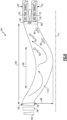
Figures 2 and 3 , with continued reference toFigure 1 , theexample separator 44 is schematically shown and utilizes swirling flows to separate heavier components produced by combustion from lighter water. For example, the components produced during combustion such as nitrogen, oxygen and carbon dioxide have molecular weights of 28, 32 and 44 respectively. Water has a molecular weight of 18. Theexample separator 44 utilizes the swirling flow ofexhaust gas 40 from theturbine section 30 to separate the components from the water.Figure 2 schematically illustrates the components of combustion asarrows 92 and water asarrows 90. Theheavier components 92 are driven radially outward toward theouter outlet 48. Thelighter water 90 is not driven radially outward as far and is communicated through theinner outlet 50. - Separation of the
components 92 andwater 90 is not total as some portion of thecomponents 92 andwater 90 will be communicated through each of the outer andinner outlets exhaust gas flow 72 contains proportionallymore water 90 than that of the firstexhaust gas flow 70. The percent difference in water content between the first and second exhaust gas flows 70, 72 may be small, but is quantifiable and sufficient to provide improved condenser efficiencies or sizing. - In one example embodiment, the second
exhaust gas flow 72 includes more than 5% more water than that of the first exhaust gas flow. In another example embodiment, the secondexhaust gas flow 72 includes more than 20% more water than that of the firstexhaust gas flow 70. For example, if the first exhaust gas flow includes five parts water per 100 parts of mass flow, the secondexhaust gas flow 72 may include more than six parts water per 100 parts of mass flow, a 20% increase. Although example ranges of water content are disclosed by way of example, other differences in water content are within the contemplation and scope of this disclosure and may provide for increased condenser efficiencies. - The
example separator 44 is disposed within anaxial length 84 between an aft mostrotating turbine blade 76 and a turbine exit guide vane (TEGV) 80. Aseparator portion 86 within theaxial length 84 provides space and time for the swirling flow exiting theturbine section 30 to generate separation of thecomponents 92 from thewater 90. In one disclosed example, theseparator portion 86 is anannular cavity 88 disposed along the engine axis A. More of theheavier components 92 are driven radially outward and exit through theouter outlet 48 into the firstexhaust gas passage 52 than exit through theinner outlet 50. Similarly, more of thelighter water 90 exits thecavity 88 through theinner outlet 50 than through theouter outlet 48 to generate the water enriched secondexhaust gas flow 72. - The
example turbine section 30, includes the aft-mostrotating blade 76, astator 78 and a secondrotating blade 82. Each of the aftrotating blade 76,stator 78 and secondrotating blade 82 represent a row of blades supported on a corresponding rotating rotor or fixed static structure in the case of thestator 78.Exhaust gas flow 40 exiting the aft-mostrotating blade 76 has some circumferential flow component that generates a swirling flow. Theexample separator 44 does not include features that induce the swirling flow, but instead provides theseparator portion 86 within an axial distance that provides the space and time for the swirling exitingexhaust gas flow 40 to induce some separation of thecomponents 92 from thewater 90. The exampleaxial length 84 may be any length that is determined to provide sufficient space and time to induce sufficient separation for generation of the water enriched secondexhaust gas flow 72. In one example embodiment, theaxial length 84 is more than ten (10) times anaxial length 85 of aturbine stage 110 including thesecond blade 82 and thestator 78. In another example embodiment, theaxial length 84 is between ten (10) and fifty (50) times the axial length of theturbine stage 110. Although axial lengths are disclosed by example, other axial lengths may be utilized and are within the contemplation and scope of this disclosure. - Referring to
Figures 4 and 5 , in another disclosed example an inner outlet 50' is disposed upstream of theTEGV 80 and is disposed at anangle 116 relative to the axis A. The inner outlet 50' is further only partially annular.Figure 5 is a schematic view of an axial cross-section through the inner outlet 50' and is disposed only a partialannular distance 118. - Referring to
Figure 6 with continued reference toFigure 1 , anotherexample separator 94 is shown schematically and includes a radiallycurved portion 96 within theaxial length 84. Aseparator portion 112 includes thecurved portion 96 to facilitate acceleration of thecomponents 92 to enhance separation. In this example, thecurved portion 96 is bent inward aradial distance 98 toward the axis A. Theexample radial distance 98 is shown schematically and exaggerated to illustrate a configuration that may provide increased separation without significant additional structures. Theradial distance 98 may be much smaller than shown to accommodate engine structures. As in the previous disclosed example, thecomponents 92 are driven radially outward toward theouter outlet 48. Thewater 90 is communicated through theinner outlet 50. The separation of at least some of thecomponents 92 into the firstexhaust gas flow 70 provides for the secondexhaust gas flow 72 to have a greater concentration ofwater 90 to improve combustor efficiency. - Referring to
Figure 7 , anotherexample separator 100 is schematically shown and includes thecurved portion 96 without the stator 78 (illustrated inFigure 4 ), and instead includes anopen space 102. Thecurved portion 96 induces swirling by accelerating the exhaust gas flow. The elimination of thestator 78 provides an additional feature for further enhancing swirling flow. Thestator 78 straightens and orientates flow betweenrotating turbine blades stator 78, theexhaust gas flow 40 begins to swirl prior to and/or upon exiting theaft-most turbine blade 76. The additional swirling provides additional forces that drive the heavier component flows 92 radially outward into the firstexhaust gas passage 52. In this example, the elimination of thelast stator 78 is combined with thecurved portion 96. However, elimination of thelast stator 78 could be implemented without thecurved portion 96 and remain within the contemplation of this disclosure. - Referring to
Figures 8 and 9 with continued reference toFigure 1 , anotherexample separator 104 is shown and includes aswirler 106 for inducing a swirling flow into theexhaust gas flow 40 aft of theaft-most blade 76. Theexample swirler 106 includes a plurality of fixed vanes 108 (Figure 9 ) that induces a swirling flow that provides the driving force utilized to separate thecomponents 92 from thewater 90. The plurality ofvanes 108 may be disposed anywhere withinseparator portion 114 in theaxial length 84. The number and angular orientation of thevanes 108 is configured to generate a desired swirling flow component to facilitate separation. Thevanes 108 may be disposed annularly about the axis A. Thevanes 108 may spirally wrap about the axis A within theseparator portion 114. - Referring to
Figure 10 , anotherexample separator portion 114 may includeindividual swirlers 116 circumferentially spaced apart about the axis A. Each of theswirlers 116 may induce a swirling flow component that provides for separation of thecomponents 92 andwater 90. Although different swirler configurations are disclosed by way of example, other swirler configurations could be utilized and are within the contemplation of this disclosure. - Accordingly, the
example propulsion system 20 provides for improved condenser efficiency by generating a water enriched gas stream for communication to thecondenser 60. - Although an example embodiment has been disclosed, a worker of ordinary skill in this art would recognize that certain modifications would come within the scope of this disclosure. For that reason, the following claims should be studied to determine the scope and content of this disclosure.
Claims (15)
- An aircraft propulsion system comprising:a compressor section (26) where an inlet airflow is compressed;a combustor section (28) where the compressed inlet airflow is mixed with fuel and ignited to generate an exhaust gas flow (40) that is communicated through a core flow path (C);a turbine section (30) through which the exhaust gas flow (40) expands to generate a mechanical power output;a condenser (60) at least partially disposed within the core flow path (C) where water is extracted from the exhaust gas flow (40);an evaporator system (56) at least partially disposed within the core flow path (C) upstream of the condenser (60) where thermal energy from the exhaust gas flow (40) is utilized to generate a steam flow (68) from at least a portion of water extracted by the condenser (60) for injection into a core flow path (C); anda core exhaust gas separator (44) where the exhaust gas flow (40) is separated into a first exhaust gas flow (70) and a second exhaust gas flow (72), wherein the second exhaust gas flow (72) contains a higher concentration of steam than the first exhaust gas flow (70).
- The aircraft propulsion system as recited in claim 1, wherein:only the second exhaust gas flow (72) is communicated to the condenser (60); and/orthe second exhaust gas flow (72) has a smaller flow volume than the first exhaust gas flow (70).
- The aircraft propulsion system as recited in claim 1 or 2, wherein thermal energy from both the first exhaust gas flow (70) and the second exhaust gas flow (72) is communicated to the evaporator system (56) for generating the steam flow (68).
- The aircraft propulsion system as recited in any preceding claim, wherein the core exhaust gas separator (44) is configured to utilize a radially directed flow to separate components of the exhaust gas flow (40) by molecular weight.
- The aircraft propulsion system as recited in any preceding claim, wherein the core exhaust gas separator (44) includes an outer outlet (48) in communication with a first exhaust gas passage (52) for the first exhaust gas flow (70) and an inner outlet (50) in communication with a second exhaust passage (54) for the second exhaust gas flow (72).
- The aircraft propulsion system as recited in claim 5, wherein the core exhaust gas separator (44) includes a separator portion (86, 112) disposed within an axial length (84) between a rotating blade (76, 82) of the turbine section (30) and an exit guide vane (80) and the outer outlet (48) and the inner outlet (50) are disposed proximate the exit guide vane (80).
- The aircraft propulsion system as recited in claim 5 or 6, wherein the core exhaust gas separator (44) includes a or the separator portion (86, 112) disposed within an or the axial length (84) between a or the rotating blade (76, 82) of the turbine section (30) and an or the exit guide vane (80) and the inner outlet (50) is disposed upstream of the exit guide vane (80) and at an angle relative to an engine longitudinal axis (A).
- The aircraft propulsion system as recited in claim 6 or 7, wherein the separator portion (112) includes a radially outward curved portion (96) for increasing rotational acceleration of the exhaust gas flow (40).
- The aircraft propulsion system as recited in any of claims 6 to 8, wherein:the aircraft propulsion system (20) further includes a fixed swirling vane assembly (106) disposed within the separator portion (86) that is configured to induce swirling in exhaust gas flow (40) entering the separator portion (86), wherein the fixed swirling vane assembly (106) comprises multiple swirling vanes (108) spaced circumferentially about an axis of rotation within the separator portion; and/orthe rotating blade (76, 82) comprises an aft most rotating blade (76) and the turbine section (30) includes a second rotating blade (82) immediately upstream of the aft most rotating blade (76) without a stator vane disposed therebetween.
- The aircraft propulsion system as recited in any of claims 5 to 9, wherein the inner outlet (50) is only partially annular about the longitudinal axis (A).
- The aircraft propulsion system as recited in any preceding claim, wherein the core exhaust gas separator (44) is annular about an engine axis (A).
- A steam generation system for a turbine engine assembly, the water extraction system comprising:a core exhaust gas separator (44) where an exhaust gas flow (40) is separated into a first exhaust gas flow (70) and a second exhaust gas flow (72), wherein the second exhaust gas flow (72) contains more water than the first exhaust gas flow (70), wherein the core exhaust gas separator (44) is configured to utilize a radially directed flow to separate components of the exhaust gas flow (40) by molecular weight;a condenser (60) where the second exhaust gas flow (72) is received and water is extracted; andan evaporator system (56) where thermal energy from the exhaust gas flow (40) is utilized to generate a steam flow (68) from at least a portion of water extracted by the condenser (60) for injection into a core flow path (C) of a turbine engine (22), optionally wherein the core exhaust gas separator (44) includes an outer outlet (48) in communication with a first exhaust gas passage (52) for the first exhaust gas flow (70) and an inner outlet (50) in communication with a second exhaust passage (54) for the second exhaust gas flow (72).
- The steam generation system as recited in claim 12, wherein a separator portion (86) includes a radially outward curved portion (96) for increasing rotational acceleration of the exhaust gas flow (40), optionally further including a fixed swirling vane assembly (106) disposed within the separator portion (86) that is configured to induce swirling in exhaust gas flow (40) entering the separator portion.
- A method of generating steam for injection into a core flow path of a turbine engine, the method comprising:separating an exhaust gas flow (40) into a first exhaust gas flow (70) and a second exhaust gas flow (72), wherein the second exhaust gas flow (72) contains more water than the first exhaust gas flow (70) and is of a smaller flow volume than the first exhaust gas flow (70);cooling the second exhaust gas flow (72) to condense water into a liquid form; andextracting liquid water from the second exhaust gas flow (72).
- The method as recited in claim 14, wherein:the method further includes heating the extracted liquid water to generate a steam flow (68) for communication to a core flow path (C); and/orseparating the exhaust gas flow (40) comprises generating a swirling flow in the exhaust gas flow (40) to communicate heavier components through an outer outlet (48) as part of the first exhaust gas flow (70) and communicating more water through an inner outlet (50) than the outer outlet (48) as the second exhaust gas flow (72).
Applications Claiming Priority (1)
| Application Number | Priority Date | Filing Date | Title |
|---|---|---|---|
| US18/458,696 US12338751B2 (en) | 2023-08-30 | 2023-08-30 | Centrifugal water molecular separation |
Publications (1)
| Publication Number | Publication Date |
|---|---|
| EP4517068A1 true EP4517068A1 (en) | 2025-03-05 |
Family
ID=92632851
Family Applications (1)
| Application Number | Title | Priority Date | Filing Date |
|---|---|---|---|
| EP24197743.8A Pending EP4517068A1 (en) | 2023-08-30 | 2024-08-30 | Extraction of water from the exhaust gas flow of a turbine engine assembly using centrifugal water molecular separation |
Country Status (2)
| Country | Link |
|---|---|
| US (1) | US12338751B2 (en) |
| EP (1) | EP4517068A1 (en) |
Families Citing this family (2)
| Publication number | Priority date | Publication date | Assignee | Title |
|---|---|---|---|---|
| US12529333B2 (en) * | 2022-07-22 | 2026-01-20 | Rtx Corporation | Partial exhaust condensation with cryogenic assisted bottoming cycle |
| US12546236B2 (en) * | 2024-04-29 | 2026-02-10 | Numerical Analysis Inc. | Parallel heat recovery in gas power generation |
Citations (4)
| Publication number | Priority date | Publication date | Assignee | Title |
|---|---|---|---|---|
| US5628183A (en) * | 1994-10-12 | 1997-05-13 | Rice; Ivan G. | Split stream boiler for combined cycle power plants |
| US20090173073A1 (en) * | 2006-08-07 | 2009-07-09 | Alstom Technology Ltd. | Method of separating co2 from a gas flow, co2 separating device for carrying out the method, swirl nozzle for a co2 separating device |
| WO2022223073A1 (en) * | 2021-04-19 | 2022-10-27 | MTU Aero Engines AG | Method for operating a flight-propulsion system |
| US11635022B1 (en) * | 2022-02-11 | 2023-04-25 | Raytheon Technologies Corporation | Reducing contrails from an aircraft powerplant |
Family Cites Families (7)
| Publication number | Priority date | Publication date | Assignee | Title |
|---|---|---|---|---|
| US3799249A (en) * | 1969-11-26 | 1974-03-26 | Air Reduction Inc | Hot gas heat exchanger |
| US7837752B2 (en) | 2007-12-03 | 2010-11-23 | Honeywell International Inc. | Water removal downstream of a turbine |
| US20150000298A1 (en) * | 2013-03-15 | 2015-01-01 | Advanced Green Technologies, Llc | Fuel conditioner, combustor and gas turbine improvements |
| US10358976B2 (en) * | 2014-10-29 | 2019-07-23 | Swapnil Sarjerao Jagtap | Heat recuperation system for the family of shaft powered aircraft gas turbine engines |
| DE102018208026A1 (en) | 2018-05-22 | 2019-11-28 | MTU Aero Engines AG | An exhaust treatment device, aircraft propulsion system, and method of treating an exhaust flow |
| US11828200B2 (en) * | 2022-02-11 | 2023-11-28 | Raytheon Technologies Corporation | Hydrogen-oxygen fueled powerplant with water and heat recovery |
| US11603798B1 (en) * | 2022-02-11 | 2023-03-14 | Raytheon Technologies Corporation | Cryogenically assisted exhaust condensation |
-
2023
- 2023-08-30 US US18/458,696 patent/US12338751B2/en active Active
-
2024
- 2024-08-30 EP EP24197743.8A patent/EP4517068A1/en active Pending
Patent Citations (4)
| Publication number | Priority date | Publication date | Assignee | Title |
|---|---|---|---|---|
| US5628183A (en) * | 1994-10-12 | 1997-05-13 | Rice; Ivan G. | Split stream boiler for combined cycle power plants |
| US20090173073A1 (en) * | 2006-08-07 | 2009-07-09 | Alstom Technology Ltd. | Method of separating co2 from a gas flow, co2 separating device for carrying out the method, swirl nozzle for a co2 separating device |
| WO2022223073A1 (en) * | 2021-04-19 | 2022-10-27 | MTU Aero Engines AG | Method for operating a flight-propulsion system |
| US11635022B1 (en) * | 2022-02-11 | 2023-04-25 | Raytheon Technologies Corporation | Reducing contrails from an aircraft powerplant |
Also Published As
| Publication number | Publication date |
|---|---|
| US12338751B2 (en) | 2025-06-24 |
| US20250075641A1 (en) | 2025-03-06 |
Similar Documents
| Publication | Publication Date | Title |
|---|---|---|
| EP4517068A1 (en) | Extraction of water from the exhaust gas flow of a turbine engine assembly using centrifugal water molecular separation | |
| US10975731B2 (en) | Turbine engine, components, and methods of cooling same | |
| US8695324B2 (en) | Multistage tip fan | |
| US7185484B2 (en) | Methods and apparatus for assembling a gas turbine engine | |
| US20110120083A1 (en) | Gas turbine engine with outer fans | |
| US8006477B2 (en) | Re-heat combustor for a gas turbine engine | |
| US20250052190A1 (en) | Turbine engine including a steam system | |
| EP4553304A1 (en) | Combustor for a gas turbine engine | |
| EP4656858A2 (en) | Circumferential flow condenser arrangement for an aircraft propulsion system | |
| EP4477856A2 (en) | Gas turbine engine with water recovery system | |
| US11927132B1 (en) | Water separator for hydrogen steam injected turbine engine | |
| EP4197621A1 (en) | Diffuser nozzle for a gas turbine engine | |
| US12571345B2 (en) | Turbine engine including a steam system | |
| US12359612B2 (en) | Turbine engine with three air streams | |
| EP4542017A1 (en) | Turbine engine with three air streams | |
| US12421873B1 (en) | Propulsion and electrical system for an aircraft including a fuel cell and turbine engine with a steam system | |
| US12241406B1 (en) | Turbine engine including a steam system | |
| US20250251129A1 (en) | Gas turbine engine having a steam generating system providing steam to a combustor | |
| EP4656860A1 (en) | Axial flow tapered condenser arrangement for an aircraft propulsion system | |
| US11459953B2 (en) | Gas turbine engine with fuel-cooled turbine | |
| EP4560129A1 (en) | Turbine engine including a steam system | |
| US20260063068A1 (en) | Evaporator system within an inner fixed structure of an aircraft propulsion system | |
| EP4617482A1 (en) | Hydrogen fuel heating with open loop waste heat recovery cycle |
Legal Events
| Date | Code | Title | Description |
|---|---|---|---|
| PUAI | Public reference made under article 153(3) epc to a published international application that has entered the european phase |
Free format text: ORIGINAL CODE: 0009012 |
|
| STAA | Information on the status of an ep patent application or granted ep patent |
Free format text: STATUS: THE APPLICATION HAS BEEN PUBLISHED |
|
| AK | Designated contracting states |
Kind code of ref document: A1 Designated state(s): AL AT BE BG CH CY CZ DE DK EE ES FI FR GB GR HR HU IE IS IT LI LT LU LV MC ME MK MT NL NO PL PT RO RS SE SI SK SM TR |
|
| STAA | Information on the status of an ep patent application or granted ep patent |
Free format text: STATUS: REQUEST FOR EXAMINATION WAS MADE |
|
| 17P | Request for examination filed |
Effective date: 20250901 |