EP4517056A1 - Integral stator vane weld shield - Google Patents
Integral stator vane weld shield Download PDFInfo
- Publication number
- EP4517056A1 EP4517056A1 EP24194970.0A EP24194970A EP4517056A1 EP 4517056 A1 EP4517056 A1 EP 4517056A1 EP 24194970 A EP24194970 A EP 24194970A EP 4517056 A1 EP4517056 A1 EP 4517056A1
- Authority
- EP
- European Patent Office
- Prior art keywords
- vane
- inches
- weld shield
- stator vane
- shield
- Prior art date
- Legal status (The legal status is an assumption and is not a legal conclusion. Google has not performed a legal analysis and makes no representation as to the accuracy of the status listed.)
- Pending
Links
Images


Classifications
-
- F—MECHANICAL ENGINEERING; LIGHTING; HEATING; WEAPONS; BLASTING
- F01—MACHINES OR ENGINES IN GENERAL; ENGINE PLANTS IN GENERAL; STEAM ENGINES
- F01D—NON-POSITIVE DISPLACEMENT MACHINES OR ENGINES, e.g. STEAM TURBINES
- F01D25/00—Component parts, details, or accessories, not provided for in, or of interest apart from, other groups
- F01D25/24—Casings; Casing parts, e.g. diaphragms, casing fastenings
- F01D25/246—Fastening of diaphragms or stator-rings
-
- F—MECHANICAL ENGINEERING; LIGHTING; HEATING; WEAPONS; BLASTING
- F01—MACHINES OR ENGINES IN GENERAL; ENGINE PLANTS IN GENERAL; STEAM ENGINES
- F01D—NON-POSITIVE DISPLACEMENT MACHINES OR ENGINES, e.g. STEAM TURBINES
- F01D25/00—Component parts, details, or accessories, not provided for in, or of interest apart from, other groups
- F01D25/28—Supporting or mounting arrangements, e.g. for turbine casing
- F01D25/285—Temporary support structures, e.g. for testing, assembling, installing, repairing; Assembly methods using such structures
-
- B—PERFORMING OPERATIONS; TRANSPORTING
- B22—CASTING; POWDER METALLURGY
- B22F—WORKING METALLIC POWDER; MANUFACTURE OF ARTICLES FROM METALLIC POWDER; MAKING METALLIC POWDER; APPARATUS OR DEVICES SPECIALLY ADAPTED FOR METALLIC POWDER
- B22F10/00—Additive manufacturing of workpieces or articles from metallic powder
- B22F10/20—Direct sintering or melting
- B22F10/28—Powder bed fusion, e.g. selective laser melting [SLM] or electron beam melting [EBM]
-
- B—PERFORMING OPERATIONS; TRANSPORTING
- B22—CASTING; POWDER METALLURGY
- B22F—WORKING METALLIC POWDER; MANUFACTURE OF ARTICLES FROM METALLIC POWDER; MAKING METALLIC POWDER; APPARATUS OR DEVICES SPECIALLY ADAPTED FOR METALLIC POWDER
- B22F7/00—Manufacture of composite layers, workpieces, or articles, comprising metallic powder, by sintering the powder, with or without compacting wherein at least one part is obtained by sintering or compression
- B22F7/06—Manufacture of composite layers, workpieces, or articles, comprising metallic powder, by sintering the powder, with or without compacting wherein at least one part is obtained by sintering or compression of composite workpieces or articles from parts, e.g. to form tipped tools
- B22F7/062—Manufacture of composite layers, workpieces, or articles, comprising metallic powder, by sintering the powder, with or without compacting wherein at least one part is obtained by sintering or compression of composite workpieces or articles from parts, e.g. to form tipped tools involving the connection or repairing of preformed parts
-
- F—MECHANICAL ENGINEERING; LIGHTING; HEATING; WEAPONS; BLASTING
- F01—MACHINES OR ENGINES IN GENERAL; ENGINE PLANTS IN GENERAL; STEAM ENGINES
- F01D—NON-POSITIVE DISPLACEMENT MACHINES OR ENGINES, e.g. STEAM TURBINES
- F01D9/00—Stators
- F01D9/02—Nozzles; Nozzle boxes; Stator blades; Guide conduits, e.g. individual nozzles
- F01D9/04—Nozzles; Nozzle boxes; Stator blades; Guide conduits, e.g. individual nozzles forming ring or sector
- F01D9/041—Nozzles; Nozzle boxes; Stator blades; Guide conduits, e.g. individual nozzles forming ring or sector using blades
-
- F—MECHANICAL ENGINEERING; LIGHTING; HEATING; WEAPONS; BLASTING
- F01—MACHINES OR ENGINES IN GENERAL; ENGINE PLANTS IN GENERAL; STEAM ENGINES
- F01D—NON-POSITIVE DISPLACEMENT MACHINES OR ENGINES, e.g. STEAM TURBINES
- F01D9/00—Stators
- F01D9/02—Nozzles; Nozzle boxes; Stator blades; Guide conduits, e.g. individual nozzles
- F01D9/04—Nozzles; Nozzle boxes; Stator blades; Guide conduits, e.g. individual nozzles forming ring or sector
- F01D9/042—Nozzles; Nozzle boxes; Stator blades; Guide conduits, e.g. individual nozzles forming ring or sector fixing blades to stators
- F01D9/044—Nozzles; Nozzle boxes; Stator blades; Guide conduits, e.g. individual nozzles forming ring or sector fixing blades to stators permanently, e.g. by welding, brazing, casting or the like
-
- F—MECHANICAL ENGINEERING; LIGHTING; HEATING; WEAPONS; BLASTING
- F01—MACHINES OR ENGINES IN GENERAL; ENGINE PLANTS IN GENERAL; STEAM ENGINES
- F01D—NON-POSITIVE DISPLACEMENT MACHINES OR ENGINES, e.g. STEAM TURBINES
- F01D9/00—Stators
- F01D9/02—Nozzles; Nozzle boxes; Stator blades; Guide conduits, e.g. individual nozzles
- F01D9/04—Nozzles; Nozzle boxes; Stator blades; Guide conduits, e.g. individual nozzles forming ring or sector
-
- F—MECHANICAL ENGINEERING; LIGHTING; HEATING; WEAPONS; BLASTING
- F05—INDEXING SCHEMES RELATING TO ENGINES OR PUMPS IN VARIOUS SUBCLASSES OF CLASSES F01-F04
- F05D—INDEXING SCHEME FOR ASPECTS RELATING TO NON-POSITIVE-DISPLACEMENT MACHINES OR ENGINES, GAS-TURBINES OR JET-PROPULSION PLANTS
- F05D2230/00—Manufacture
- F05D2230/20—Manufacture essentially without removing material
- F05D2230/23—Manufacture essentially without removing material by permanently joining parts together
- F05D2230/232—Manufacture essentially without removing material by permanently joining parts together by welding
- F05D2230/234—Laser welding
-
- F—MECHANICAL ENGINEERING; LIGHTING; HEATING; WEAPONS; BLASTING
- F05—INDEXING SCHEMES RELATING TO ENGINES OR PUMPS IN VARIOUS SUBCLASSES OF CLASSES F01-F04
- F05D—INDEXING SCHEME FOR ASPECTS RELATING TO NON-POSITIVE-DISPLACEMENT MACHINES OR ENGINES, GAS-TURBINES OR JET-PROPULSION PLANTS
- F05D2230/00—Manufacture
- F05D2230/30—Manufacture with deposition of material
-
- F—MECHANICAL ENGINEERING; LIGHTING; HEATING; WEAPONS; BLASTING
- F05—INDEXING SCHEMES RELATING TO ENGINES OR PUMPS IN VARIOUS SUBCLASSES OF CLASSES F01-F04
- F05D—INDEXING SCHEME FOR ASPECTS RELATING TO NON-POSITIVE-DISPLACEMENT MACHINES OR ENGINES, GAS-TURBINES OR JET-PROPULSION PLANTS
- F05D2230/00—Manufacture
- F05D2230/80—Repairing, retrofitting or upgrading methods
Definitions
- the present disclosure relates generally to gas turbine engine stator vane rings and, more particularly, to a replacement stator vane made with a powder bed fusion additive machine.
- gas turbine engines include a compressor section, combustor section, and turbine section.
- Many gas turbine engines used for aviation propulsion include a fan section upstream of the compressor section and, in some configurations, a gear box between the fan section and the compressor section.
- the compressor section may be further divided into two or more compressors (e.g., a low pressure compressor and a high pressure compressor).
- the turbine section may be divided into two or more turbines (e.g., high pressure turbine and a low pressure turbine).
- the compressors and turbines are formed from successive stages of stationary vanes (i.e., stator vanes) and rotating blades.
- compressor stator vanes and blades are typically solid parts and can be formed as complete stator vane rings (for compressor vanes) or integrally bladed rotors (for compressor blades). Such components can be made using traditional casting methods or by additive manufacturing methods. Regardless of the manufacturing method used to make these parts, these parts, particularly stator vane rings, can have low yields that result in many parts being scrapped.
- One aspect of the present invention is directed to a stator vane for a gas turbine engine combustor having a vane segment that includes a vane having a leading edge, a trailing edge, a suction side, a pressure side, a vane inner base, and a vane outer base, an inner shroud segment attached to the vane at the vane inner base, and an outer shroud segment attached to the vane at the vane outer base.
- the stator vane further includes a support structure attached to the vane at a vane trailing edge, and a first weld shield attached to the support structure by a first connector. The first weld shield is positioned over and spaced away from the suction side.
- the vane, inner shroud segment, outer shroud segment, support structure, and first weld shield are integrally formed during a single, continuous additive manufacturing process.
- the stator vane of the preceding paragraph can optionally include, additionally and/or alternatively, any one or more of the following features, configurations and/or additional elements:
- the first weld shield is between 0.002 inches (0.0508 mm) and 0.012 inches (0.3048 mm) thick
- the first connector is at least 0.012 inches (0.3048 mm) thick
- the first weld shield is spaced away from the suction side by at least 0.010 inches (0.254 mm).
- the first weld shield and the support structure are configured to be removed from the vane segment after installation of the stator vane into a stator vane ring.
- the additive manufacturing process is a powder bed fusion additive manufacturing process.
- the stator vane further comprises: a second weld shield attached to the support structure by a second connector, wherein the second weld shield is positioned over and spaced away from the pressure side, wherein the vane, inner shroud segment, outer shroud segment, support structure, first connector, first weld shield, second connector, and second weld shield are integrally formed during a single, continuous additive manufacturing process.
- the first weld shield is between 0.002 inches (0.0508 mm) and 0.012 inches (0.3048 mm) thick
- the first connector is at least 0.012 inches (0.3048 mm) thick
- the first weld shield is spaced away from the suction side by at least 0.010 inches (0.254 mm)
- the second weld shield is between 0.002 inches (0.0508 mm) and 0.012 inches (0.3048 mm) thick
- the second connector is at least 0.012 inches (0.3048 mm) thick
- the second weld shield is spaced away from the pressure side by at least 0.010 inches (0.254 mm).
- the first weld shield, the second weld shield, and the support structure are configured to be removed from the vane segment after installation of the stator vane into a stator vane ring.
- the additive manufacturing process is a powder bed fusion additive manufacturing process.
- Another aspect of the present invention is directed to a method of making a stator vane for a gas turbine engine combustor that includes integrally forming during a single, continuous additive manufacturing process: a vane segment having a vane having a leading edge, a trailing edge, a suction side, a pressure side, a vane inner base, and a vane outer base; an inner shroud segment attached to the vane at the vane inner base; and an outer shroud segment attached to the vane at the vane outer base.
- a support structure attached to the vane at a vane trailing edge; and a first weld shield attached to the support structure by a first connector are also integrally formed during the same single, continuous additive manufacturing process.
- the first weld shield is positioned over and spaced away from the suction side.
- the method of the preceding paragraph can optionally include, additionally and/or alternatively, any one or more of the following features, configurations and/or additional elements:
- the first weld shield is between 0.002 inches (0.0508 mm) and 0.012 inches (0.3048 mm) thick
- the first connector is at least 0.012 inches (0.3048 mm) thick
- the first weld shield is spaced away from the suction side by at least 0.010 inches (0.254 mm).
- the first weld shield and the support structure are configured to be removed from the vane segment after installation of the stator vane into a stator vane ring.
- the additive manufacturing process is a powder bed fusion additive manufacturing process.
- the method further comprises integrally forming during the same single, continuous additive manufacturing process a second weld shield attached to the support structure by a second connector, wherein the second weld shield is positioned over and spaced away from the pressure side.
- the method comprises removing the first weld shield, the second weld shield, and the support shield from the stator vane.
- the first weld shield is between 0.002 inches (0.0508 mm) and 0.012 inches (0.3048 mm) thick
- the first connector is at least 0.012 inches (0.3048 mm) thick
- the first weld shield is spaced away from the suction side by at least 0.010 inches (0.254 mm)
- the second weld shield is between 0.002 inches (0.0508 mm) and 0.012 inches (0.3048 mm) thick
- the second connector is at least 0.012 inches (0.3048 mm) thick
- the second weld shield is spaced away from the pressure side by at least 0.010 inches (0.254 mm).
- the first weld shield, the second weld shield, and the support structure are configured to be removed from the vane segment after installation of the stator vane into a stator vane ring.
- the additive manufacturing process is a powder bed fusion additive manufacturing process.
- Yet another aspect of the present invention is directed to a method of replacing a damaged stator vane in a gas turbine engine combustor stator vane ring, including identifying the damaged stator vane in the gas turbine engine combustor stator vane ring, removing the damaged stator vane from the gas turbine engine combustor stator vane ring to create an opening in the gas turbine engine combustor stator vane ring, inserting into the opening in the gas turbine engine combustor stator vane ring a stator vane described above, and removing the first weld shield and the support shield from the stator vane.
- the method of the preceding paragraph can optionally include, additionally and/or alternatively, any one or more of the following features, configurations and/or additional elements:
- the first weld shield is between 0.002 inches (0.0508 mm) and 0.012 inches (0.3048 mm) thick
- the first connector is at least 0.012 inches (0.3048 mm) thick
- the first weld shield is spaced away from the suction side by at least 0.010 inches (0.254 mm).
- the first weld shield is between 0.002 inches (0.0508 mm) and 0.012 inches (0.3048 mm) thick
- the first connector is at least 0.012 inches (0.3048 mm) thick
- the first weld shield is spaced away from the suction side by at least 0.010 inches (0.254 mm)
- the second weld shield is between 0.002 inches (0.0508 mm) and 0.012 inches (0.3048 mm) thick
- the second connector is at least 0.012 inches (0.3048 mm) thick
- the second weld shield is spaced away from the pressure side by at least 0.010 inches (0.254 mm).
- Gas turbine engine compressor stator vane rings can be made using traditional manufacturing methods (e.g., forging, casting, and other traditional methods) or by additive manufacturing methods, including powder bed fusion (PBF) additive manufacturing (AM) methods.
- PBF AM is an additive manufacturing, or 3-D printing, technology that uses an energy source, such as a laser (PBF-LB) or electron beam (PBF-EB), to sinter or fuse metallic or polymeric particles together in a layer-by-layer process.
- PBF is typically used as an industrial process to make near net shape parts with various geometries.
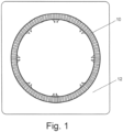
- Fig. 1 shows a non-limiting, exemplary gas turbine engine compressor stator vane ring 10 made using a PBF AM process.
- annular-shaped parts such as the gas turbine engine compressor stator vane ring 10
- stator vane rings can have low yields that result in many parts being scrapped.
- the present disclosure is directed to replacement stator vanes made with AM methods, such as PBF AM methods, that can be used to address defects in gas turbine engine compressor stator vane rings.
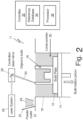
- Fig. 2 is a schematic of an exemplary, non-limiting PBF-LB system 11. While this disclosure is applicable to all PBF systems, including PBF-LB and PBF-EB systems, the exemplary, non-limiting PBF-LB system 11 will be used to describe the AM system and method of the disclosure.
- a typical PBF-LB system 11 includes a build plate 12, a build station piston 14 that adjusts the height of the build plate 12, a part or part 16 that is built on top of the build plate 12, a powder chamber 18 to contain loose, and unconsolidated build powder 20 that surrounds the part 16.
- a typical PBF-LB system 11 also includes a powder coater 22 that distributes additional build powder 24 over the part 16 after completion of each layer formed on the part 16.
- a recoater blade 25 follows the powder coater 22 as it distributes additional build powder 24 to create an even layer of consolidated built powder 20.
- the recoater blade 25 can be made from silicone, polyurethane, rubber, or other elastomeric materials.
- a laser system 26 combined with a controlled laser mirror 28 directs a laser beam 30 onto loose build powder 20 to form a melt pool (not shown) that, when solidified, forms a layer of the part 16.
- the build station piston 14 lowers the built plate 12 and part 16 by a predetermined distance that corresponds to the desired thickness of the next layer of the part 16.
- the powder coater 22 then moves across the top of the loose build powder 20 to distribute a layer of additional build powder 24 that will then be consolidated with the laser beam 30 to form the next layer of the part 16.
- Controller 32 controls the height of the build plate 12 by moving the build station piston 14, which in turn controls the thickness of each layer of the part 16. Controller 32 also controls the movement of the powder coater 22 as it distributes additional build powder 24 and the movement of the laser beam 30 as it forms the melt pool that consolidates loose build powder 20 to form each layer of the part 16. For example, the controller 32 controls PBF-LB system 10 operating parameters, including:
- Controller 32 typically includes a reference database 34 and processor 36.
- Reference database 34 contains processing data relevant to the PBF-LB system 10, build powder to be used to produce the part 16, and the specific work piece 16 to be produced.
- Processor 36 contains programming to interface with the reference database 34 to control the PBF-LB system 10 to products parts, such as part 16, as is known to a person of ordinary skill in the art.
- Part 16 can be a near-net-shaped part (i.e., initial production of the part that is very close to the final (net) shape).
- the PBF-LB system 11 can be used with a variety of build powders to produce part 24.
- the powder can be a metal powder or polymeric powder.
- Metallic powders compatible with typical PBF-LB systems 11 include aluminum, aluminum alloys (e.g., aluminum-lithium alloys), titanium, nickel, nickel alloys, and other metals and alloys known in the art.
- Polymeric powders compatible with typical PBF-LB systems 11 include a wide variety of polymers as known in the art.
- Fig. 3 shows a segment of an inner compressor stator vane ring 40 that includes a plurality of stator vanes 42 fixed into the stator vane ring 40.
- One of the stator vanes 42 is shaded to depict a donor stator vane 44 that was inserted into the stator vane ring 40 to replace a defective stator vane.
- One option for making a donor stator vane 44 is to use PBF-LB AM techniques.
- the defective stator vane 42 is excised from the stator vane ring 40, for example, using wire electrical discharge machining (EDM) techniques, to create an opening into which the donor stator vane 44 can be inserted and welded into place.
- EDM wire electrical discharge machining
- the welding procedure used to secure the donor stator vane 44 to the stator vane ring 40 can result in weld spatter depositing onto the donor stator vane 44.
- Weld spatter deposited on the donor stator vane 44 requires removal, which is an additional operation that adds cost to the vane replacement process and can potentially damage the donor stator vane 44.
- Fig. 4 shows one configuration of a donor stator vane 44 made with PBF-LB AM techniques that includes an inner shroud segment 46, a vane segment 48, and an outer shroud segment 50.
- the vane segment 48 includes a leading edge 52, a trailing edge 54, a suction side 56, a pressure side 58, a vane inner base 60, and a vane outer base 62.
- the vane segment 48 has a support structure 64 formed on the trailing edge 54.
- the inner shroud segment 46, vane segment 48, and outer shroud segment 50 are portions of the donor stator vane 44 that are used operationally after the donor stator vane 44 is inserted into the stator vane ring 40.
- the support structure 64 is formed on the donor stator vane 44 during the PBF-LB AM process to support the donor stator vane 44 during processing.
- the support structure 64 is removed after the donor stator vane 44 is inserted into the stator vane ring 40 and welded into place.
- the donor stator vane 44 and all of its constituent parts i.e., the inner shroud segment 46, vane segment 48, outer shroud segment 50 and support structure 64
- the donor stator vane 44, stator vane ring 40, and the other the stator vanes 42 can be made from any suitable material for a gas turbine engine compressor section component, such as titanium.
- Fig. 5 shows another configuration of a donor stator vane 44 made with PBF-LB AM techniques.
- the donor stator vane 44 of Fig. 5 includes an inner shroud segment 46, a vane segment 48 (not visible in Fig. 5 ), an outer shroud segment 50, a support structure 64 (formed on the trailing edge 54 of the vane segment 48 as in the example of Fig. 4 ), and a weld shield 66 that is formed above the vane segment 48 and is spaced away from the vane segment 48.
- the weld shield 66 obscures vane segment 48 in Fig. 5 due to its position above and spaced away from the vane segment 48.
- the weld shield 66 can be spaced away from the vane segment 48 by at least 0.010 inches (0.254 mm).
- the weld shield 66 is formed integrally with (i.e., formed as a unit of the same structure during a single, continuous additive manufacturing process) the support structure 64 and is connected to the support structure 64 by connector 68.
- the connector 68 can be a very thin "line-on-line" structure that can be defined as an "infinitely thin" structure between the weld shield 66 and the support structure 64.
- the connector 68 can be formed by a single laser beam pass during the PBF-LB AM process used to make the donor stator vane 44.
- the connector 68 can be at least 0.012 inches (0.3048 mm) thick, for example, between 0.012 inches (0.3048 mm) to 0.030 inches (0.762 mm) thick or between 0.015 inches (0.381 mm) to 0.030 inches (0.762 mm) thick or any other thickness deemed appropriate for a particular operation.
- the weld shield 66 is also a thin structure that can be about the thickness of a sheet of paper, for example, about 0.004 inches (0.1016 mm) thick. In various examples, the weld shield 66 can be between 0.002 inches (0.0508 mm) and 0.012 inches (0.3048 mm) thick.
- the donor stator vane 44 can have one (a first) weld shield 66 positioned over the suction side 56 of the vane segment 48 and a second weld shield (not shown) positioned over the pressure side 58 of the vane segment 48.
- the second weld shield (not shown) can be connected to the support structure 64 with a second connector (also not shown).
- the donor stator vane 44 of Fig. 5 (i.e., having either a single weld shield 66, or a combination of the first weld shield 66 and a second weld shield) is inserted in the position in the vane ring 40 from which the defective vane 42 was excised and the donor stator vane 44 is welded into place.
- Weld spatter from the weld operation deposits onto the weld shield 66 (or a combination of the first weld shield 66 and the second weld shield) rather than on the vane segment 48, obviating the need to remove weld spatter from the vane segment 48 as would be the case for a donor stator vane 44 that does not include the weld shield 66 (or a combination of the first weld shield 66 and the second weld shield).
- the welding operation used to secure the donor stator vane 44 to the vane ring 40 leaves a residual indication (i.e., the weld bead around the donor stator vane 44) that the vane replacement was made.
- the weld shield 66 (or a combination of the first weld shield 66 and the second weld shield) can be removed by hand or using hand tools while leaving little or no residual material.
- the support structure 64 should likewise be removed from the donor stator vane 44 using hand tools or light machining leaving little or no residual material. Any residual material remaining after removal of the weld shield 66 and supporting structure 64 can be removed by media blasting or other mechanical techniques.
- any residual material remaining after all of the operations is in a less aerodynamically sensitive portion of the vane segment 48 than if it had been attached to the leading edge 52 of the vane segment 48.
- the donor stator vane 44 and related processes of this disclosure provide a number of benefits.
- Printing the weld shield 66 does not significantly increase build time and removal can be done manually without extensive fixturing or tooling. Mitigating the need to further reduce surface roughness will reduce cost of the repair.
- Weld spatter will not deposit on the critical surfaces of the vane segment 48 and instead land on the weld shield 66 which functions as an ablative surface.
- This technique can be applied to other similar vanes additively manufactured using PBF-LB and is not limited specifically to a particular stage.
- a stator vane for a gas turbine engine combustor comprises a vane segment having a vane having a leading edge, a trailing edge, a suction side, a pressure side, a vane inner base, and a vane outer base; an inner shroud segment attached to the vane at the vane inner base; and an outer shroud segment attached to the vane at the vane outer base.
- the stator vane further comprises a support structure attached to the vane at a vane trailing edge; and a first weld shield attached to the support structure by a first connector.
- the first weld shield is positioned over and spaced away from the suction side, and the vane, inner shroud segment, outer shroud segment, support structure, and first weld shield are integrally formed during a single, continuous additive manufacturing process.
- the stator vane of the preceding paragraph can optionally include, additionally and/or alternatively, any one or more of the following features, configurations and/or additional elements:
- the stator vane of the preceding paragraph wherein the first weld shield is between 0.002 inches (0.0508 mm) and 0.012 inches (0.3048 mm) thick, the first connector is at least 0.012 inches (0.3048 mm) thick, and the first weld shield is spaced away from the suction side by at least 0.010 inches (0.254 mm).
- stator vane of any of the preceding paragraphs wherein the first weld shield and the support structure are configured to be removed from the vane segment after installation of the stator vane into a stator vane ring.
- stator vane of the preceding paragraph wherein the additive manufacturing process is a powder bed fusion additive manufacturing process.
- the first weld shield is between 0.002 inches (0.0508 mm) and 0.012 inches (0.3048 mm) thick
- the first connector is at least 0.012 inches (0.3048 mm) thick
- the first weld shield is spaced away from the suction side by at least 0.010 inches (0.254 mm)
- the second weld shield is between 0.002 inches (0.0508 mm) and 0.012 inches (0.3048 mm) thick
- the second connector is at least 0.012 inches (0.3048 mm) thick
- the second weld shield is spaced away from the pressure side by at least 0.010 inches (0.254 mm).
- a method of replacing a damaged stator vane in a gas turbine engine combustor stator vane ring comprising identifying the damaged stator vane in the gas turbine engine combustor stator vane ring; removing the damaged stator vane from the gas turbine engine combustor stator vane ring to create an opening in the gas turbine engine combustor stator vane ring; inserting into the opening in the gas turbine engine combustor stator vane ring a stator vane of claim 1; and removing the first weld shield and the support shield from the stator vane.
- the method of the preceding paragraph can optionally include, additionally and/or alternatively, any one or more of the following features, configurations and/or additional elements:
- the method of the preceding paragraph wherein the first weld shield is between 0.002 inches (0.0508 mm) and 0.012 inches (0.3048 mm) thick, the first connector is at least 0.012 inches (0.3048 mm) thick, and the first weld shield is spaced away from the suction side by at least 0.010 inches (0.254 mm).
Landscapes
- Engineering & Computer Science (AREA)
- Mechanical Engineering (AREA)
- General Engineering & Computer Science (AREA)
- Chemical & Material Sciences (AREA)
- Manufacturing & Machinery (AREA)
- Materials Engineering (AREA)
- Composite Materials (AREA)
- Physics & Mathematics (AREA)
- Plasma & Fusion (AREA)
- Structures Of Non-Positive Displacement Pumps (AREA)
- Turbine Rotor Nozzle Sealing (AREA)
Abstract
A stator vane (44) for a gas turbine engine combustor has a vane segment (48) that includes a vane having a leading edge (52), a trailing edge (54), a suction side (56), a pressure side, a vane inner base (60), and a vane outer base (62), an inner shroud segment (46) attached to the vane at the vane inner base (60), and an outer shroud segment (50) attached to the vane at the vane outer base (62). The stator vane (44) further includes a support structure (64) attached to the vane at a vane trailing edge, and a first weld shield (66) attached to the support structure (64) by a first connector (68). The first weld shield (66) is positioned over and spaced away from the suction side (56). The vane, inner shroud segment (46), outer shroud segment (50), support structure (64), and first weld shield (66) are integrally formed during a single, continuous additive manufacturing process.
Description
- The present disclosure relates generally to gas turbine engine stator vane rings and, more particularly, to a replacement stator vane made with a powder bed fusion additive machine.
- As well known, gas turbine engines include a compressor section, combustor section, and turbine section. Many gas turbine engines used for aviation propulsion include a fan section upstream of the compressor section and, in some configurations, a gear box between the fan section and the compressor section. The compressor section may be further divided into two or more compressors (e.g., a low pressure compressor and a high pressure compressor). Similarly, the turbine section may be divided into two or more turbines (e.g., high pressure turbine and a low pressure turbine). The compressors and turbines are formed from successive stages of stationary vanes (i.e., stator vanes) and rotating blades. While turbine blades and vanes typically include internal cooling features that require them to be cast as individual parts, compressor stator vanes and blades are typically solid parts and can be formed as complete stator vane rings (for compressor vanes) or integrally bladed rotors (for compressor blades). Such components can be made using traditional casting methods or by additive manufacturing methods. Regardless of the manufacturing method used to make these parts, these parts, particularly stator vane rings, can have low yields that result in many parts being scrapped.
- One aspect of the present invention is directed to a stator vane for a gas turbine engine combustor having a vane segment that includes a vane having a leading edge, a trailing edge, a suction side, a pressure side, a vane inner base, and a vane outer base, an inner shroud segment attached to the vane at the vane inner base, and an outer shroud segment attached to the vane at the vane outer base. The stator vane further includes a support structure attached to the vane at a vane trailing edge, and a first weld shield attached to the support structure by a first connector. The first weld shield is positioned over and spaced away from the suction side. The vane, inner shroud segment, outer shroud segment, support structure, and first weld shield are integrally formed during a single, continuous additive manufacturing process.
- The stator vane of the preceding paragraph can optionally include, additionally and/or alternatively, any one or more of the following features, configurations and/or additional elements:
In an embodiment of the above, the first weld shield is between 0.002 inches (0.0508 mm) and 0.012 inches (0.3048 mm) thick, the first connector is at least 0.012 inches (0.3048 mm) thick, and the first weld shield is spaced away from the suction side by at least 0.010 inches (0.254 mm). - In an embodiment according to any of the previous embodiments, the first weld shield and the support structure are configured to be removed from the vane segment after installation of the stator vane into a stator vane ring.
- In an embodiment according to any of the previous embodiments, the additive manufacturing process is a powder bed fusion additive manufacturing process.
- In an embodiment according to any of the previous embodiments, the stator vane further comprises: a second weld shield attached to the support structure by a second connector, wherein the second weld shield is positioned over and spaced away from the pressure side, wherein the vane, inner shroud segment, outer shroud segment, support structure, first connector, first weld shield, second connector, and second weld shield are integrally formed during a single, continuous additive manufacturing process.
- In an embodiment according to any of the previous embodiments, the first weld shield is between 0.002 inches (0.0508 mm) and 0.012 inches (0.3048 mm) thick, the first connector is at least 0.012 inches (0.3048 mm) thick, and the first weld shield is spaced away from the suction side by at least 0.010 inches (0.254 mm) and the second weld shield is between 0.002 inches (0.0508 mm) and 0.012 inches (0.3048 mm) thick, the second connector is at least 0.012 inches (0.3048 mm) thick, and the second weld shield is spaced away from the pressure side by at least 0.010 inches (0.254 mm).
- In an embodiment according to any of the previous embodiments, the first weld shield, the second weld shield, and the support structure are configured to be removed from the vane segment after installation of the stator vane into a stator vane ring.
- In an embodiment according to any of the previous embodiments, the additive manufacturing process is a powder bed fusion additive manufacturing process.
Another aspect of the present invention is directed to a method of making a stator vane for a gas turbine engine combustor that includes integrally forming during a single, continuous additive manufacturing process: a vane segment having a vane having a leading edge, a trailing edge, a suction side, a pressure side, a vane inner base, and a vane outer base; an inner shroud segment attached to the vane at the vane inner base; and an outer shroud segment attached to the vane at the vane outer base. A support structure attached to the vane at a vane trailing edge; and a first weld shield attached to the support structure by a first connector are also integrally formed during the same single, continuous additive manufacturing process. The first weld shield is positioned over and spaced away from the suction side. - The method of the preceding paragraph can optionally include, additionally and/or alternatively, any one or more of the following features, configurations and/or additional elements:
In an embodiment of the above, the first weld shield is between 0.002 inches (0.0508 mm) and 0.012 inches (0.3048 mm) thick, the first connector is at least 0.012 inches (0.3048 mm) thick, and the first weld shield is spaced away from the suction side by at least 0.010 inches (0.254 mm). - In an embodiment according to any of the previous embodiments, the first weld shield and the support structure are configured to be removed from the vane segment after installation of the stator vane into a stator vane ring.
- In an embodiment according to any of the previous embodiments, the additive manufacturing process is a powder bed fusion additive manufacturing process.
- In an embodiment according to any of the previous embodiments, the method further comprises integrally forming during the same single, continuous additive manufacturing process a second weld shield attached to the support structure by a second connector, wherein the second weld shield is positioned over and spaced away from the pressure side.
- In an embodiment of the above, the method comprises removing the first weld shield, the second weld shield, and the support shield from the stator vane.
- In an embodiment according to any of the previous embodiments, the first weld shield is between 0.002 inches (0.0508 mm) and 0.012 inches (0.3048 mm) thick, the first connector is at least 0.012 inches (0.3048 mm) thick, and the first weld shield is spaced away from the suction side by at least 0.010 inches (0.254 mm) and the second weld shield is between 0.002 inches (0.0508 mm) and 0.012 inches (0.3048 mm) thick, the second connector is at least 0.012 inches (0.3048 mm) thick, and the second weld shield is spaced away from the pressure side by at least 0.010 inches (0.254 mm).
- In an embodiment according to any of the previous embodiments, the first weld shield, the second weld shield, and the support structure are configured to be removed from the vane segment after installation of the stator vane into a stator vane ring.
- In an embodiment according to any of the previous embodiments, the additive manufacturing process is a powder bed fusion additive manufacturing process.
- Yet another aspect of the present invention is directed to a method of replacing a damaged stator vane in a gas turbine engine combustor stator vane ring, including identifying the damaged stator vane in the gas turbine engine combustor stator vane ring, removing the damaged stator vane from the gas turbine engine combustor stator vane ring to create an opening in the gas turbine engine combustor stator vane ring, inserting into the opening in the gas turbine engine combustor stator vane ring a stator vane described above, and removing the first weld shield and the support shield from the stator vane.
- The method of the preceding paragraph can optionally include, additionally and/or alternatively, any one or more of the following features, configurations and/or additional elements:
In an embodiment of the above, the first weld shield is between 0.002 inches (0.0508 mm) and 0.012 inches (0.3048 mm) thick, the first connector is at least 0.012 inches (0.3048 mm) thick, and the first weld shield is spaced away from the suction side by at least 0.010 inches (0.254 mm). - In an embodiment according to any of the previous embodiments, the first weld shield is between 0.002 inches (0.0508 mm) and 0.012 inches (0.3048 mm) thick, the first connector is at least 0.012 inches (0.3048 mm) thick, and the first weld shield is spaced away from the suction side by at least 0.010 inches (0.254 mm) and the second weld shield is between 0.002 inches (0.0508 mm) and 0.012 inches (0.3048 mm) thick, the second connector is at least 0.012 inches (0.3048 mm) thick, and the second weld shield is spaced away from the pressure side by at least 0.010 inches (0.254 mm).
-
-
Fig. 1 is an illustration of one type of annular-shaped build that can be made with a powder bed fusion (PBF) additive manufacturing system. -
Fig. 2 is a schematic of an exemplary laser powder bed fusion (PBF-LB) additive manufacturing system. -
Fig 3 is a view of a segment of a gas turbine engine compressor stator ring. -
Fig. 4 is an example donor stator vane made on a PBF-LB manufacturing system. -
Fig. 5 is another example donor stator vane made on a PBF-LB manufacturing system. - Gas turbine engine compressor stator vane rings can be made using traditional manufacturing methods (e.g., forging, casting, and other traditional methods) or by additive manufacturing methods, including powder bed fusion (PBF) additive manufacturing (AM) methods. PBF AM is an additive manufacturing, or 3-D printing, technology that uses an energy source, such as a laser (PBF-LB) or electron beam (PBF-EB), to sinter or fuse metallic or polymeric particles together in a layer-by-layer process. PBF is typically used as an industrial process to make near net shape parts with various geometries.
Fig. 1 shows a non-limiting, exemplary gas turbine engine compressorstator vane ring 10 made using a PBF AM process. Generally, annular-shaped parts, such as the gas turbine engine compressorstator vane ring 10, can be printed in their entirety in a large format PBF AM machine, often on a rectangular orsquare build plates 12. Regardless of the manufacturing method (i.e., traditional methods or AM methods) used to make gas turbine engine compressor stator vane rings, stator vane rings can have low yields that result in many parts being scrapped. The present disclosure is directed to replacement stator vanes made with AM methods, such as PBF AM methods, that can be used to address defects in gas turbine engine compressor stator vane rings. -
Fig. 2 is a schematic of an exemplary, non-limiting PBF-LB system 11. While this disclosure is applicable to all PBF systems, including PBF-LB and PBF-EB systems, the exemplary, non-limiting PBF-LB system 11 will be used to describe the AM system and method of the disclosure. A typical PBF-LB system 11 includes abuild plate 12, abuild station piston 14 that adjusts the height of thebuild plate 12, a part orpart 16 that is built on top of thebuild plate 12, apowder chamber 18 to contain loose, andunconsolidated build powder 20 that surrounds thepart 16. A typical PBF-LB system 11 also includes apowder coater 22 that distributesadditional build powder 24 over thepart 16 after completion of each layer formed on thepart 16. Arecoater blade 25 follows thepowder coater 22 as it distributesadditional build powder 24 to create an even layer of consolidated built powder 20.Therecoater blade 25 can be made from silicone, polyurethane, rubber, or other elastomeric materials. Alaser system 26 combined with a controlledlaser mirror 28 directs alaser beam 30 ontoloose build powder 20 to form a melt pool (not shown) that, when solidified, forms a layer of thepart 16. As each layer of thepart 16 is formed, thebuild station piston 14 lowers the builtplate 12 andpart 16 by a predetermined distance that corresponds to the desired thickness of the next layer of thepart 16. Thepowder coater 22 then moves across the top of theloose build powder 20 to distribute a layer ofadditional build powder 24 that will then be consolidated with thelaser beam 30 to form the next layer of thepart 16. -
Controller 32 controls the height of thebuild plate 12 by moving thebuild station piston 14, which in turn controls the thickness of each layer of thepart 16.Controller 32 also controls the movement of thepowder coater 22 as it distributesadditional build powder 24 and the movement of thelaser beam 30 as it forms the melt pool that consolidatesloose build powder 20 to form each layer of thepart 16. For example, thecontroller 32 controls PBF-LB system 10 operating parameters, including: - (1) laser beam power, laser beam velocity, and laser beam spot size, build plate temperature, and layer thickness;
- (2) temperature-dependent thermophysical properties of the powder;
- (3) feedstock properties including average powder particle size; and
- (4) laser hatching strategy including hatch distance, hatch delay time, and stripe width.
-
Controller 32 typically includes areference database 34 andprocessor 36.Reference database 34 contains processing data relevant to the PBF-LB system 10, build powder to be used to produce thepart 16, and thespecific work piece 16 to be produced.Processor 36 contains programming to interface with thereference database 34 to control the PBF-LB system 10 to products parts, such aspart 16, as is known to a person of ordinary skill in the art.Part 16 can be a near-net-shaped part (i.e., initial production of the part that is very close to the final (net) shape). - The PBF-
LB system 11 can be used with a variety of build powders to producepart 24. For example the powder can be a metal powder or polymeric powder. Metallic powders compatible with typical PBF-LB systems 11 include aluminum, aluminum alloys (e.g., aluminum-lithium alloys), titanium, nickel, nickel alloys, and other metals and alloys known in the art. Polymeric powders compatible with typical PBF-LB systems 11 include a wide variety of polymers as known in the art. -
Fig. 3 shows a segment of an inner compressorstator vane ring 40 that includes a plurality ofstator vanes 42 fixed into thestator vane ring 40. One of thestator vanes 42 is shaded to depict adonor stator vane 44 that was inserted into thestator vane ring 40 to replace a defective stator vane. One option for making adonor stator vane 44 is to use PBF-LB AM techniques. Thedefective stator vane 42 is excised from thestator vane ring 40, for example, using wire electrical discharge machining (EDM) techniques, to create an opening into which thedonor stator vane 44 can be inserted and welded into place. The welding procedure used to secure thedonor stator vane 44 to thestator vane ring 40 can result in weld spatter depositing onto thedonor stator vane 44. Weld spatter deposited on thedonor stator vane 44 requires removal, which is an additional operation that adds cost to the vane replacement process and can potentially damage thedonor stator vane 44. -
Fig. 4 shows one configuration of adonor stator vane 44 made with PBF-LB AM techniques that includes aninner shroud segment 46, avane segment 48, and anouter shroud segment 50. Thevane segment 48 includes aleading edge 52, a trailingedge 54, asuction side 56, apressure side 58, a vaneinner base 60, and a vaneouter base 62. Thevane segment 48 has asupport structure 64 formed on the trailingedge 54. Theinner shroud segment 46,vane segment 48, andouter shroud segment 50 are portions of thedonor stator vane 44 that are used operationally after thedonor stator vane 44 is inserted into thestator vane ring 40. Thesupport structure 64 is formed on thedonor stator vane 44 during the PBF-LB AM process to support thedonor stator vane 44 during processing. Thesupport structure 64 is removed after thedonor stator vane 44 is inserted into thestator vane ring 40 and welded into place. Thedonor stator vane 44 and all of its constituent parts (i.e., theinner shroud segment 46,vane segment 48,outer shroud segment 50 and support structure 64) should be made from the same material as thestator vane ring 40 and the other the stator vanes 42. For example, thedonor stator vane 44,stator vane ring 40, and the other thestator vanes 42 can be made from any suitable material for a gas turbine engine compressor section component, such as titanium. -
Fig. 5 shows another configuration of adonor stator vane 44 made with PBF-LB AM techniques. Thedonor stator vane 44 ofFig. 5 includes aninner shroud segment 46, a vane segment 48 (not visible inFig. 5 ), anouter shroud segment 50, a support structure 64 (formed on the trailingedge 54 of thevane segment 48 as in the example ofFig. 4 ), and aweld shield 66 that is formed above thevane segment 48 and is spaced away from thevane segment 48. Theweld shield 66 obscuresvane segment 48 inFig. 5 due to its position above and spaced away from thevane segment 48. For example, theweld shield 66 can be spaced away from thevane segment 48 by at least 0.010 inches (0.254 mm). Theweld shield 66 is formed integrally with (i.e., formed as a unit of the same structure during a single, continuous additive manufacturing process) thesupport structure 64 and is connected to thesupport structure 64 byconnector 68. Theconnector 68 can be a very thin "line-on-line" structure that can be defined as an "infinitely thin" structure between theweld shield 66 and thesupport structure 64. For example, theconnector 68 can be formed by a single laser beam pass during the PBF-LB AM process used to make thedonor stator vane 44. Theconnector 68 can be at least 0.012 inches (0.3048 mm) thick, for example, between 0.012 inches (0.3048 mm) to 0.030 inches (0.762 mm) thick or between 0.015 inches (0.381 mm) to 0.030 inches (0.762 mm) thick or any other thickness deemed appropriate for a particular operation. Theweld shield 66 is also a thin structure that can be about the thickness of a sheet of paper, for example, about 0.004 inches (0.1016 mm) thick. In various examples, theweld shield 66 can be between 0.002 inches (0.0508 mm) and 0.012 inches (0.3048 mm) thick. - While the example for
Fig. 5 depicts asingle weld shield 66 over thesuction side 56 of the vane segment 48 (seeFig. 4 ), in another example (not expressly shown inFig. 5 ), thedonor stator vane 44 can have one (a first)weld shield 66 positioned over thesuction side 56 of thevane segment 48 and a second weld shield (not shown) positioned over thepressure side 58 of thevane segment 48. As with thefirst weld shield 66 discussed above, the second weld shield (not shown) can be connected to thesupport structure 64 with a second connector (also not shown). The second weld shield and second connector are similarly formed integrally (i.e., i.e., formed as a unit of the same structure during a single, continuous additive manufacturing process) with thesupport structure 64 and have the same thickness as thefirst weld shield 66 andconnector 68 discussed above and be spaced away from thepressure side 58 of thevane segment 48 by the same distance that thefirst weld shield 66 is spaced away from thesuction side 56 of thevane segment 48. The weld shield 66 (or a combination of thefirst weld shield 66 and the second weld shield) remains in place after it is formed integrally with thesupport structure 64 and after removal from the PBF-LP machine build plate. - After being formed, the
donor stator vane 44 ofFig. 5 (i.e., having either asingle weld shield 66, or a combination of thefirst weld shield 66 and a second weld shield) is inserted in the position in thevane ring 40 from which thedefective vane 42 was excised and thedonor stator vane 44 is welded into place. Weld spatter from the weld operation deposits onto the weld shield 66 (or a combination of thefirst weld shield 66 and the second weld shield) rather than on thevane segment 48, obviating the need to remove weld spatter from thevane segment 48 as would be the case for adonor stator vane 44 that does not include the weld shield 66 (or a combination of thefirst weld shield 66 and the second weld shield). The welding operation used to secure thedonor stator vane 44 to thevane ring 40 leaves a residual indication (i.e., the weld bead around the donor stator vane 44) that the vane replacement was made. - The weld shield 66 (or a combination of the
first weld shield 66 and the second weld shield) should remain in place during the weld process used to secure thedonor stator vane 44 tovane ring 40. Once thedonor stator vane 44 is welded to thevane ring 40, the weld shield 66 (or a combination of thefirst weld shield 66 and the second weld shield) can be removed from thesupport structure 64. Because of the verythin connector 68 connecting the weld shield 66 (or a combination of thefirst weld shield 66 and the second weld shield) to thesupport structure 64, the weld shield 66 (or a combination of thefirst weld shield 66 and the second weld shield) can be removed by hand or using hand tools while leaving little or no residual material. Thesupport structure 64 should likewise be removed from thedonor stator vane 44 using hand tools or light machining leaving little or no residual material. Any residual material remaining after removal of theweld shield 66 and supportingstructure 64 can be removed by media blasting or other mechanical techniques. Because thesupport structure 64 is formed on the trailingedge 54 of thevane segment 48, any residual material remaining after all of the operations is in a less aerodynamically sensitive portion of thevane segment 48 than if it had been attached to the leadingedge 52 of thevane segment 48. - The
donor stator vane 44 and related processes of this disclosure provide a number of benefits. Printing theweld shield 66 does not significantly increase build time and removal can be done manually without extensive fixturing or tooling. Mitigating the need to further reduce surface roughness will reduce cost of the repair. Weld spatter will not deposit on the critical surfaces of thevane segment 48 and instead land on theweld shield 66 which functions as an ablative surface. This technique can be applied to other similar vanes additively manufactured using PBF-LB and is not limited specifically to a particular stage. - The following are non-exclusive descriptions of possible embodiments of the present invention.
- A stator vane for a gas turbine engine combustor comprises a vane segment having a vane having a leading edge, a trailing edge, a suction side, a pressure side, a vane inner base, and a vane outer base; an inner shroud segment attached to the vane at the vane inner base; and an outer shroud segment attached to the vane at the vane outer base. The stator vane further comprises a support structure attached to the vane at a vane trailing edge; and a first weld shield attached to the support structure by a first connector. The first weld shield is positioned over and spaced away from the suction side, and the vane, inner shroud segment, outer shroud segment, support structure, and first weld shield are integrally formed during a single, continuous additive manufacturing process.
- The stator vane of the preceding paragraph can optionally include, additionally and/or alternatively, any one or more of the following features, configurations and/or additional elements:
The stator vane of the preceding paragraph, wherein the first weld shield is between 0.002 inches (0.0508 mm) and 0.012 inches (0.3048 mm) thick, the first connector is at least 0.012 inches (0.3048 mm) thick, and the first weld shield is spaced away from the suction side by at least 0.010 inches (0.254 mm). - The stator vane of any of the preceding paragraphs, wherein the first weld shield and the support structure are configured to be removed from the vane segment after installation of the stator vane into a stator vane ring.
- The stator vane of any of the preceding paragraphs, wherein the additive manufacturing process is a powder bed fusion additive manufacturing process.
- The stator vane of any of the preceding paragraphs, further comprising: a second weld shield attached to the support structure by a second connector, wherein the second weld shield is positioned over and spaced away from the pressure side, wherein the vane, inner shroud segment, outer shroud segment, support structure, first connector, first weld shield, second connector, and second weld shield are integrally formed during a single, continuous additive manufacturing process.
- The stator vane of the preceding paragraph, wherein the first weld shield is between 0.002 inches (0.0508 mm) and 0.012 inches (0.3048 mm) thick, the first connector is at least 0.012 inches (0.3048 mm) thick, and the first weld shield is spaced away from the suction side by at least 0.010 inches (0.254 mm) and the second weld shield is between 0.002 inches (0.0508 mm) and 0.012 inches (0.3048 mm) thick, the second connector is at least 0.012 inches (0.3048 mm) thick, and the second weld shield is spaced away from the pressure side by at least 0.010 inches (0.254 mm).
- The stator vane of the preceding paragraph, wherein the first weld shield, the second weld shield, and the support structure are configured to be removed from the vane segment after installation of the stator vane into a stator vane ring.
- The stator vane of the preceding paragraph, wherein the additive manufacturing process is a powder bed fusion additive manufacturing process.
- A method of making a stator vane for a gas turbine engine combustor comprises integrally forming during a single, continuous additive manufacturing process a vane segment including a vane having a leading edge, a trailing edge, a suction side, a pressure side, a vane inner base, and a vane outer base; an inner shroud segment attached to the vane at the vane inner base; and an outer shroud segment attached to the vane at the vane outer base; a support structure attached to the vane at a vane trailing edge; and a first weld shield attached to the support structure by a first connector, wherein the first weld shield is positioned over and spaced away from the suction side.
- The method of the preceding paragraph can optionally include, additionally and/or alternatively, any one or more of the following features, configurations and/or additional elements:
The method of the preceding paragraph, wherein the first weld shield is between 0.002 inches (0.0508 mm) and 0.012 inches (0.3048 mm) thick, the first connector is at least 0.012 inches (0.3048 mm) thick, and the first weld shield is spaced away from the suction side by at least 0.010 inches (0.254 mm). - The method of any of the preceding paragraphs, wherein the first weld shield and the support structure are configured to be removed from the vane segment after installation of the stator vane into a stator vane ring.
- The method of any of the preceding paragraphs, wherein the additive manufacturing process is a powder bed fusion additive manufacturing process.
- The method of any of the preceding paragraphs, further comprising integrally forming during the same single, continuous additive manufacturing process a second weld shield attached to the support structure by a second connector, wherein the second weld shield is positioned over and spaced away from the pressure side.
- The method of the preceding paragraph, wherein the first weld shield is between 0.002 inches (0.0508 mm) and 0.012 inches (0.3048 mm) thick, the first connector is at least 0.012 inches (0.3048 mm) thick, and the first weld shield is spaced away from the suction side by at least 0.010 inches (0.254 mm) and the second weld shield is between 0.002 inches (0.0508 mm) and 0.012 inches (0.3048 mm) thick, the second connector is at least 0.012 inches (0.3048 mm) thick, and the second weld shield is spaced away from the pressure side by at least 0.010 inches (0.254 mm).
- The method of the preceding paragraph, wherein the first weld shield, the second weld shield, and the support structure are configured to be removed from the vane segment after installation of the stator vane into a stator vane ring.
- The method of the preceding paragraph, wherein the additive manufacturing process is a powder bed fusion additive manufacturing process.
- A method of replacing a damaged stator vane in a gas turbine engine combustor stator vane ring, comprising identifying the damaged stator vane in the gas turbine engine combustor stator vane ring; removing the damaged stator vane from the gas turbine engine combustor stator vane ring to create an opening in the gas turbine engine combustor stator vane ring; inserting into the opening in the gas turbine engine combustor stator vane ring a stator vane of claim 1; and removing the first weld shield and the support shield from the stator vane.
- The method of the preceding paragraph can optionally include, additionally and/or alternatively, any one or more of the following features, configurations and/or additional elements:
The method of the preceding paragraph, wherein the first weld shield is between 0.002 inches (0.0508 mm) and 0.012 inches (0.3048 mm) thick, the first connector is at least 0.012 inches (0.3048 mm) thick, and the first weld shield is spaced away from the suction side by at least 0.010 inches (0.254 mm). - The method of the preceding paragraph, wherein the steps of inserting into the opening in the gas turbine engine combustor stator vane ring a stator vane of claim 1; and removing the first weld shield and the support shield from the stator vane; are replaced with the steps of: inserting into the opening in the gas turbine engine combustor stator vane ring a stator vane of claim 5; and removing the first weld shield, the second weld shield, and the support shield from the stator vane.
- The method of the preceding paragraph, wherein the first weld shield is between 0.002 inches (0.0508 mm) and 0.012 inches (0.3048 mm) thick, the first connector is at least 0.012 inches (0.3048 mm) thick, and the first weld shield is spaced away from the suction side by at least 0.010 inches (0.254 mm) and the second weld shield is between 0.002 inches (0.0508 mm) and 0.012 inches (0.3048 mm) thick, the second connector is at least 0.012 inches (0.3048 mm) thick, and the second weld shield is spaced away from the pressure side by at least 0.010 inches (0.254 mm).
- While the invention has been described with reference to an exemplary embodiment(s), it will be understood by those skilled in the art that various changes may be made and equivalents may be substituted for elements thereof without departing from the scope of the invention. In addition, many modifications may be made to adapt a particular situation or material to the teachings of the invention without departing from the essential scope thereof. Therefore, it is intended that the invention not be limited to the particular embodiment(s) disclosed, but that the invention will include all embodiments falling within the scope of the appended claims.
Claims (15)
- A stator vane for a gas turbine engine combustor comprising:a vane segment (48) comprising:a vane having a leading edge (52), a trailing edge (54), a suction side (56), a pressure side (58), a vane inner base (60), and a vane outer base (62);an inner shroud segment (46) attached to the vane at the vane inner base (60); andan outer shroud segment (50) attached to the vane at the vane outer base (62);a support structure (64) attached to the vane at the trailing edge (54); anda first weld shield (66) attached to the support structure (64) by a first connector (68), wherein the first weld shield (66) is positioned over and spaced away from the suction side (56), wherein the vane, inner shroud segment (46), outer shroud segment (50), support structure (64), and first weld shield (66) are integrally formed during a single, continuous additive manufacturing process.
- The stator vane of claim 1, wherein the first weld shield (66) is between 0.002 inches (0.0508 mm) and 0.012 inches (0.3048 mm) thick, the first connector (68) is at least 0.012 inches (0.3048 mm) thick, and the first weld shield (66) is spaced away from the suction side (56) by at least 0.010 inches (0.254 mm).
- The stator vane of claim 1 or 2, wherein the first weld shield (66) and the support structure (64) are configured to be removed from the vane segment (48) after installation of the stator vane (44) into a stator vane ring (40).
- The stator vane of any preceding claim, further comprising a second weld shield attached to the support structure (64) by a second connector, wherein the second weld shield is positioned over and spaced away from the pressure side (58), wherein the vane, inner shroud segment (46), outer shroud segment (50), support structure (64), first connector (68), first weld shield (66), second connector, and second weld shield are integrally formed during a single, continuous additive manufacturing process.
- The stator vane of claim 4, wherein the second weld shield is between 0.002 inches (0.0508 mm) and 0.012 inches (0.3048 mm) thick, the second connector is at least 0.012 inches (0.3048 mm) thick, and the second weld shield is spaced away from the pressure side (58) by at least 0.010 inches (0.254 mm).
- The stator vane of claim 4 or 5, wherein the first weld shield (66), the second weld shield, and the support structure (64) are configured to be removed from the vane segment (48) after installation of the stator vane (44) into a stator vane ring (40).
- The stator vane of any preceding claim, wherein the additive manufacturing process is a powder bed fusion additive manufacturing process.
- A method of making a stator vane for a gas turbine engine combustor comprising:
integrally forming during a single, continuous additive manufacturing process:a vane segment (48) comprising:a vane having a leading edge (52), a trailing edge (54), a suction side (56), a pressure side (58), a vane inner base (60), and a vane outer base (62);an inner shroud segment (46) attached to the vane at the vane inner base (60); andan outer shroud segment (50) attached to the vane at the vane outer base (62);a support structure (64) attached to the vane at the trailing edge (54); anda first weld shield (66) attached to the support structure (64) by a first connector (68), wherein the first weld shield (66) is positioned over and spaced away from the suction side (56). - The method of claim 8, wherein the first weld shield (66) is between 0.002 inches (0.0508 mm) and 0.012 inches (0.3048 mm) thick, the first connector (68) is at least 0.012 inches (0.3048 mm) thick, and the first weld shield (66) is spaced away from the suction side (56) by at least 0.010 inches (0.254 mm).
- The method of claim 8 or 9, wherein the first weld shield (66) and the support structure (64) are configured to be removed from the vane segment (48) after installation of the stator vane (44) into a stator vane ring (40).
- The method of any of claims 8 to 10, wherein the additive manufacturing process is a powder bed fusion additive manufacturing process.
- The method of any of claims 8 to 11, further comprising integrally forming during the same single, continuous additive manufacturing process a second weld shield attached to the support structure (64) by a second connector, wherein the second weld shield is positioned over and spaced away from the pressure side (58), optionally wherein:the second weld shield is between 0.002 inches (0.0508 mm) and 0.012 inches (0.3048 mm) thick, the second connector is at least 0.012 inches (0.3048 mm) thick, and the second weld shield is spaced away from the pressure side (58) by at least 0.010 inches (0.254 mm); and/orthe first weld shield (66), the second weld shield, and the support structure (64) are configured to be removed from the vane segment (48) after installation of the stator vane (44) into a stator vane ring (40).
- A method of replacing a damaged stator vane in a gas turbine engine combustor stator vane ring, comprising:identifying the damaged stator vane (44) in the gas turbine engine combustor stator vane ring (40);removing the damaged stator vane (44) from the gas turbine engine combustor stator vane ring (40) to create an opening in the gas turbine engine combustor stator vane ring (40);inserting the stator vane (44) of claim 1 into the opening in the gas turbine engine combustor stator vane ring (40); andremoving the first weld shield (66) and the support shield from the stator vane (44).
- The method of claim 13, wherein:the stator vane (44) comprises a second weld shield attached to the support structure (64) by a second connector, wherein the second weld shield is positioned over and spaced away from the pressure side (58), wherein the vane, inner shroud segment (46), outer shroud segment (50), support structure (64), first connector (68), first weld shield (66), second connector, and second weld shield are integrally formed during a single, continuous additive manufacturing process; andthe method comprises removing the second weld shield from the stator vane (44).
- The method of claim 13 or 14, wherein the first weld shield (66) is between 0.002 inches (0.0508 mm) and 0.012 inches (0.3048 mm) thick, the first connector (68) is at least 0.012 inches (0.3048 mm) thick, and the first weld shield (66) is spaced away from the suction side (56) by at least 0.010 inches (0.254 mm) and the second weld shield is between 0.002 inches (0.0508 mm) and 0.012 inches (0.3048 mm) thick, the second connector is at least 0.012 inches (0.3048 mm) thick, and the second weld shield is spaced away from the pressure side (58) by at least 0.010 inches (0.254 mm).
Applications Claiming Priority (1)
| Application Number | Priority Date | Filing Date | Title |
|---|---|---|---|
| US18/453,093 US12253003B1 (en) | 2023-08-21 | 2023-08-21 | Integral stator vane weld shield |
Publications (1)
| Publication Number | Publication Date |
|---|---|
| EP4517056A1 true EP4517056A1 (en) | 2025-03-05 |
Family
ID=92458056
Family Applications (1)
| Application Number | Title | Priority Date | Filing Date |
|---|---|---|---|
| EP24194970.0A Pending EP4517056A1 (en) | 2023-08-21 | 2024-08-16 | Integral stator vane weld shield |
Country Status (2)
| Country | Link |
|---|---|
| US (1) | US12253003B1 (en) |
| EP (1) | EP4517056A1 (en) |
Citations (3)
| Publication number | Priority date | Publication date | Assignee | Title |
|---|---|---|---|---|
| US20070235505A1 (en) * | 2004-07-24 | 2007-10-11 | Mtu Aero Engines Gmbh | Method for Repairing or Manufacturing a Component |
| US20180010458A1 (en) * | 2016-07-08 | 2018-01-11 | General Electric Company | Coupon for hot gas path component having manufacturing assist features |
| EP3351320A2 (en) * | 2017-01-23 | 2018-07-25 | General Electric Company | System and method for the hybrid construction of multi-piece parts |
Family Cites Families (19)
| Publication number | Priority date | Publication date | Assignee | Title |
|---|---|---|---|---|
| US5182855A (en) * | 1990-12-13 | 1993-02-02 | General Electric Company | Turbine nozzle manufacturing method |
| US6233822B1 (en) * | 1998-12-22 | 2001-05-22 | General Electric Company | Repair of high pressure turbine shrouds |
| DE19963371A1 (en) * | 1999-12-28 | 2001-07-12 | Alstom Power Schweiz Ag Baden | Chilled heat shield |
| US6494677B1 (en) * | 2001-01-29 | 2002-12-17 | General Electric Company | Turbine nozzle segment and method of repairing same |
| US7247000B2 (en) * | 2004-08-30 | 2007-07-24 | Honeywell International, Inc. | Weld shielding device for automated welding of impellers and blisks |
| US7425118B2 (en) * | 2005-10-27 | 2008-09-16 | Honeywell International Inc. | Mask for shielding impellers and blisks during automated welding |
| US8950069B2 (en) * | 2006-12-29 | 2015-02-10 | Rolls-Royce North American Technologies, Inc. | Integrated compressor vane casing |
| US8083465B2 (en) * | 2008-09-05 | 2011-12-27 | United Technologies Corporation | Repaired turbine exhaust strut heat shield vanes and repair methods |
| RU2539404C2 (en) * | 2010-11-29 | 2015-01-20 | Альстом Текнолоджи Лтд | Axial gas turbine |
| US9085980B2 (en) * | 2011-03-04 | 2015-07-21 | Honeywell International Inc. | Methods for repairing turbine components |
| US9266170B2 (en) * | 2012-01-27 | 2016-02-23 | Honeywell International Inc. | Multi-material turbine components |
| EP2949873A1 (en) * | 2014-05-27 | 2015-12-02 | Siemens Aktiengesellschaft | Turbomachine with an ingestion shield and use of the turbomachine |
| US10060272B2 (en) * | 2015-01-30 | 2018-08-28 | Rolls-Royce Corporation | Turbine vane with load shield |
| US10196910B2 (en) * | 2015-01-30 | 2019-02-05 | Rolls-Royce Corporation | Turbine vane with load shield |
| IT201600092574A1 (en) * | 2016-09-14 | 2018-03-14 | Danieli Off Mecc | PROTECTION DEVICE FOR WELDING SPRAYS WITH INTEGRATED CLEANING SYSTEM |
| GB201707101D0 (en) * | 2017-05-04 | 2017-06-21 | Rolls Royce Plc | Vane arrangement for a gas turbine engine |
| US11980938B2 (en) * | 2020-11-24 | 2024-05-14 | Rolls-Royce Corporation | Bladed disk repair process with shield |
| US11512611B2 (en) * | 2021-02-09 | 2022-11-29 | General Electric Company | Stator apparatus for a gas turbine engine |
| US12571311B2 (en) * | 2022-10-25 | 2026-03-10 | General Electric Company | Erosion-shielded turbine blades and methods of manufacturing the same |
-
2023
- 2023-08-21 US US18/453,093 patent/US12253003B1/en active Active
-
2024
- 2024-08-16 EP EP24194970.0A patent/EP4517056A1/en active Pending
Patent Citations (3)
| Publication number | Priority date | Publication date | Assignee | Title |
|---|---|---|---|---|
| US20070235505A1 (en) * | 2004-07-24 | 2007-10-11 | Mtu Aero Engines Gmbh | Method for Repairing or Manufacturing a Component |
| US20180010458A1 (en) * | 2016-07-08 | 2018-01-11 | General Electric Company | Coupon for hot gas path component having manufacturing assist features |
| EP3351320A2 (en) * | 2017-01-23 | 2018-07-25 | General Electric Company | System and method for the hybrid construction of multi-piece parts |
Also Published As
| Publication number | Publication date |
|---|---|
| US20250067198A1 (en) | 2025-02-27 |
| US12253003B1 (en) | 2025-03-18 |
Similar Documents
| Publication | Publication Date | Title |
|---|---|---|
| EP1604770B1 (en) | Method of replacing damaged aerofoil | |
| EP2317075B1 (en) | Method for repairing a gas turbine component | |
| EP1227218B1 (en) | Method of repairing a turbine nozzle segment | |
| US9951632B2 (en) | Hybrid bonded turbine rotors and methods for manufacturing the same | |
| EP1685923B1 (en) | Repair and reclassification of superalloy components | |
| US10895157B2 (en) | Gas turbine engine components with air-cooling features, and related methods of manufacturing the same | |
| EP1965023A2 (en) | Repaired vane assemblies and methods of repairing vane assemblies | |
| EP1422381B1 (en) | Method of repairing a turbine nozzle segment, and turbine nozzle segment | |
| EP1674665B1 (en) | Turbine nozzle segment and method of repairing the same | |
| US20100064515A1 (en) | Method for repairing and/or replacing individual elements of a gas turbine component | |
| EP2753799B2 (en) | Nutreparatur einer rotordrahtdichtung | |
| EP3434395B1 (en) | Method for repairing a component by additive manufacturing | |
| EP3381603B1 (en) | Hybrid article, method for forming hybrid article and method for welding | |
| US12253003B1 (en) | Integral stator vane weld shield | |
| EP2412930B1 (en) | Turbine nozzle segment and method of repairing same | |
| EP4361399A1 (en) | Manufacturing method for forming an erosion shield and an erosion-shielded turbine blade | |
| EP4360780A1 (en) | Erosion-shielded turbine blades and methods of manufacturing the same | |
| EP4538504A1 (en) | Erosion compensated vane geometry | |
| JP2024505777A (en) | Method of forming or repairing parts with overhangs and related turbomachinery parts | |
| JP2024505779A (en) | Method for forming or repairing parts with overhangs and related turbomachinery parts |
Legal Events
| Date | Code | Title | Description |
|---|---|---|---|
| PUAI | Public reference made under article 153(3) epc to a published international application that has entered the european phase |
Free format text: ORIGINAL CODE: 0009012 |
|
| STAA | Information on the status of an ep patent application or granted ep patent |
Free format text: STATUS: THE APPLICATION HAS BEEN PUBLISHED |
|
| AK | Designated contracting states |
Kind code of ref document: A1 Designated state(s): AL AT BE BG CH CY CZ DE DK EE ES FI FR GB GR HR HU IE IS IT LI LT LU LV MC ME MK MT NL NO PL PT RO RS SE SI SK SM TR |
|
| STAA | Information on the status of an ep patent application or granted ep patent |
Free format text: STATUS: REQUEST FOR EXAMINATION WAS MADE |
|
| 17P | Request for examination filed |
Effective date: 20250829 |