EP4517050A1 - Cmc vane with rotatable baffle design to accommodate re-stagger - Google Patents
Cmc vane with rotatable baffle design to accommodate re-stagger Download PDFInfo
- Publication number
- EP4517050A1 EP4517050A1 EP24195731.5A EP24195731A EP4517050A1 EP 4517050 A1 EP4517050 A1 EP 4517050A1 EP 24195731 A EP24195731 A EP 24195731A EP 4517050 A1 EP4517050 A1 EP 4517050A1
- Authority
- EP
- European Patent Office
- Prior art keywords
- vane
- bathtub
- seal
- baffle
- airfoil
- Prior art date
- Legal status (The legal status is an assumption and is not a legal conclusion. Google has not performed a legal analysis and makes no representation as to the accuracy of the status listed.)
- Pending
Links
Images


Classifications
-
- F—MECHANICAL ENGINEERING; LIGHTING; HEATING; WEAPONS; BLASTING
- F01—MACHINES OR ENGINES IN GENERAL; ENGINE PLANTS IN GENERAL; STEAM ENGINES
- F01D—NON-POSITIVE DISPLACEMENT MACHINES OR ENGINES, e.g. STEAM TURBINES
- F01D5/00—Blades; Blade-carrying members; Heating, heat-insulating, cooling or antivibration means on the blades or the members
- F01D5/12—Blades
- F01D5/14—Form or construction
- F01D5/18—Hollow blades, i.e. blades with cooling or heating channels or cavities; Heating, heat-insulating or cooling means on blades
- F01D5/187—Convection cooling
- F01D5/188—Convection cooling with an insert in the blade cavity to guide the cooling fluid, e.g. forming a separation wall
- F01D5/189—Convection cooling with an insert in the blade cavity to guide the cooling fluid, e.g. forming a separation wall the insert having a tubular cross-section, e.g. airfoil shape
-
- F—MECHANICAL ENGINEERING; LIGHTING; HEATING; WEAPONS; BLASTING
- F01—MACHINES OR ENGINES IN GENERAL; ENGINE PLANTS IN GENERAL; STEAM ENGINES
- F01D—NON-POSITIVE DISPLACEMENT MACHINES OR ENGINES, e.g. STEAM TURBINES
- F01D5/00—Blades; Blade-carrying members; Heating, heat-insulating, cooling or antivibration means on the blades or the members
- F01D5/12—Blades
- F01D5/14—Form or construction
- F01D5/18—Hollow blades, i.e. blades with cooling or heating channels or cavities; Heating, heat-insulating or cooling means on blades
- F01D5/187—Convection cooling
-
- F—MECHANICAL ENGINEERING; LIGHTING; HEATING; WEAPONS; BLASTING
- F01—MACHINES OR ENGINES IN GENERAL; ENGINE PLANTS IN GENERAL; STEAM ENGINES
- F01D—NON-POSITIVE DISPLACEMENT MACHINES OR ENGINES, e.g. STEAM TURBINES
- F01D5/00—Blades; Blade-carrying members; Heating, heat-insulating, cooling or antivibration means on the blades or the members
- F01D5/12—Blades
- F01D5/28—Selecting particular materials; Particular measures relating thereto; Measures against erosion or corrosion
- F01D5/282—Selecting composite materials, e.g. blades with reinforcing filaments
-
- F—MECHANICAL ENGINEERING; LIGHTING; HEATING; WEAPONS; BLASTING
- F01—MACHINES OR ENGINES IN GENERAL; ENGINE PLANTS IN GENERAL; STEAM ENGINES
- F01D—NON-POSITIVE DISPLACEMENT MACHINES OR ENGINES, e.g. STEAM TURBINES
- F01D9/00—Stators
- F01D9/02—Nozzles; Nozzle boxes; Stator blades; Guide conduits, e.g. individual nozzles
- F01D9/04—Nozzles; Nozzle boxes; Stator blades; Guide conduits, e.g. individual nozzles forming ring or sector
- F01D9/041—Nozzles; Nozzle boxes; Stator blades; Guide conduits, e.g. individual nozzles forming ring or sector using blades
-
- F—MECHANICAL ENGINEERING; LIGHTING; HEATING; WEAPONS; BLASTING
- F01—MACHINES OR ENGINES IN GENERAL; ENGINE PLANTS IN GENERAL; STEAM ENGINES
- F01D—NON-POSITIVE DISPLACEMENT MACHINES OR ENGINES, e.g. STEAM TURBINES
- F01D9/00—Stators
- F01D9/02—Nozzles; Nozzle boxes; Stator blades; Guide conduits, e.g. individual nozzles
- F01D9/04—Nozzles; Nozzle boxes; Stator blades; Guide conduits, e.g. individual nozzles forming ring or sector
- F01D9/042—Nozzles; Nozzle boxes; Stator blades; Guide conduits, e.g. individual nozzles forming ring or sector fixing blades to stators
-
- F—MECHANICAL ENGINEERING; LIGHTING; HEATING; WEAPONS; BLASTING
- F01—MACHINES OR ENGINES IN GENERAL; ENGINE PLANTS IN GENERAL; STEAM ENGINES
- F01D—NON-POSITIVE DISPLACEMENT MACHINES OR ENGINES, e.g. STEAM TURBINES
- F01D11/00—Preventing or minimising internal leakage of working-fluid, e.g. between stages
- F01D11/001—Preventing or minimising internal leakage of working-fluid, e.g. between stages for sealing space between stator blade and rotor
-
- F—MECHANICAL ENGINEERING; LIGHTING; HEATING; WEAPONS; BLASTING
- F01—MACHINES OR ENGINES IN GENERAL; ENGINE PLANTS IN GENERAL; STEAM ENGINES
- F01D—NON-POSITIVE DISPLACEMENT MACHINES OR ENGINES, e.g. STEAM TURBINES
- F01D5/00—Blades; Blade-carrying members; Heating, heat-insulating, cooling or antivibration means on the blades or the members
- F01D5/12—Blades
- F01D5/14—Form or construction
- F01D5/18—Hollow blades, i.e. blades with cooling or heating channels or cavities; Heating, heat-insulating or cooling means on blades
Definitions
- This application relates to a method and apparatus for utilizing re-staggering with gas turbine engine static vanes formed of ceramic matrix composites.
- Gas turbine engines typically include a fan delivering air into a bypass duct as propulsion air.
- the air is also delivered into a compressor and from the compressor into a combustor.
- the air is mixed with fuel and ignited in the combustor, and products of the combustion pass downstream through turbine rotor stages driving them to rotate.
- the turbine rotors in turn drives the fan and compressor rotors.
- CMCs ceramic matrix composites
- the turbine section typically includes rotating turbine blades axially alternating with rows of static vanes.
- the static vanes may sometimes be re-staggered, meaning the orientation of one or more airfoils in a static vane row are adjusted relative to others.
- Re-stagger may be utilized to adjust for variation in an individual vane due to manufacturing tolerances.
- re-stagger is sometimes utilized to achieve a desired turbine stage flow area based upon an upstream flow in the compressor section.
- a method of forming a vane assembly for a gas turbine engine includes the steps of 1) determining a re-stagger angle for an airfoil on a ceramic matrix composite ("CMC") vane, 2) determining an adjusted position of a baffle to be inserted within a central chamber in the vane, inserting the baffle into a bathtub seal, and adjusting an upper face of the baffle to an orientation relative to a bathtub seal support face to account for the adjusted position of the baffle and 3) fixing the baffle upper face to the bathtub seal flange support face.
- CMC ceramic matrix composite
- step 3 is performed by brazing.
- the fixed bathtub seal and baffle are inserted into the central chamber in the vane and the vane is then mounted into a vane row with the bathtub seal providing support between the vane, the baffle and static structure.
- the static structure includes a first vane support having a tab extending into a seal chamber defined between an inner and an outer wall of the bathtub seal.
- a mount structure on an upper surface of a vane platform is provided with a coating on an outer surface, and adjusts the coating to account for the re-stagger angle of the airfoil and connecting the mount structure on the vane to the bathtub seal.
- the mount structure of the vane is connected to the bathtub seal through a flange cap secured across the outer wall of the bathtub seal and the mount structure.
- the method includes the steps of assembling a vane row of a plurality of the vanes with at least a first vane having the airfoil with a first re-stagger angle that is different relative to at least the airfoil of a second of the plurality of vanes and the orientation of the baffle upper face relative to the bathtub seal support face is distinct between the first vane and the second vane.
- a vane assembly in another aspect of the present invention, includes a vane having an outer platform with mount structure and an airfoil extending inwardly from the mount structure and formed of ceramic matrix composites ("CMC").
- the vane has an internal cooling chamber.
- a metal baffle is received within the internal cooling chamber and extends beyond the platform to an upper face fixed to a bathtub seal at a bathtub seal support face, and an orientation of the upper face relative to the bathtub seal support face is adjusted to accommodate a re-stagger angle on the airfoil of the vane.
- the upper face and the support face are brazed together.
- the vane is mounted into a vane row with the bathtub seal providing support between the vane, the baffle and static structure.
- the static structure includes a first vane support having a tab extending into a seal chamber defined between an inner and an outer wall of the bathtub seal.
- a mount structure on an upper surface of a vane platform is provided with a coating on an outer surface.
- a flange cap extends across the mount structure of the vane and across an outer wall of the bathtub seal.
- a flange cap extends across the mount structure of the vane and across the outer wall of the bathtub seal.
- the vane assembly includes a vane row of a plurality of the vanes with at least a first vane having the airfoil with a first re-stagger angle that is different relative to at least the airfoil of a second of the plurality of vanes and the orientation of the baffle upper face relative to the bathtub seal support face is distinct between the first vane and the second vane.
- a gas turbine engine in another aspect of the present invention, includes a compressor section, a combustor and a turbine section.
- the turbine section includes rotating blade rows alternating with static vane rows.
- the vane rows include a vane assembly having a plurality of vanes with an outer platform having mount structure and an airfoil extending inwardly from the mount structure and the vane formed of ceramic matrix composites ("CMC").
- CMC ceramic matrix composites
- the vane has an internal cooling chamber.
- a metal baffle is received within the internal cooling chamber and extends beyond the platform to an upper face fixed to a bathtub seal at a bathtub seal support face. An orientation of the upper face relative to the bathtub seal support face is adjusted to accommodate a re-stagger angle on the airfoil of the vane.
- the upper face and the support face are brazed together.
- the vane is mounted into a vane row with the bathtub seal providing support between the vane and the baffle and static structure.
- a plurality of the vanes including a first vane having an airfoil with a first re-stagger angle that is different relative to at least the airfoil of a second of the plurality of vanes and the orientation of the upper face relative to the bathtub seal support face is distinct between the first vane and the second vane.
- a plurality of the vanes including a first vane having an airfoil with a first re-stagger angle that is different relative to at least the airfoil of a second of the plurality of vanes and the orientation of the upper face relative to the bathtub seal support face is distinct between the first vane and the second vane.
- the present disclosure may include any one or more of the individual features disclosed above and/or below alone or in any combination thereof.
- FIG. 1 schematically illustrates a gas turbine engine 20.
- the gas turbine engine 20 is disclosed herein as a two-spool turbofan that generally incorporates a fan section 22, a compressor section 24, a combustor section 26 and a turbine section 28.
- the fan section 22 may include a single-stage fan 42 having a plurality of fan blades 43.
- the fan blades 43 may have a fixed stagger angle or may have a variable pitch to direct incoming airflow from an engine inlet.
- the fan 42 drives air along a bypass flow path B in a bypass duct 13 defined within a housing 15 such as a fan case or nacelle, and also drives air along a core flow path C for compression and communication into the combustor section 26 then expansion through the turbine section 28.
- a splitter 29 aft of the fan 42 divides the air between the bypass flow path B and the core flow path C.
- the housing 15 may surround the fan 42 to establish an outer diameter of the bypass duct 13.
- the splitter 29 may establish an inner diameter of the bypass duct 13.
- the exemplary engine 20 generally includes a low speed spool 30 and a high speed spool 32 mounted for rotation about an engine central longitudinal axis A relative to an engine static structure 36 via several bearing systems 38. It should be understood that various bearing systems 38 at various locations may alternatively or additionally be provided, and the location of bearing systems 38 may be varied as appropriate to the application.
- the low speed spool 30 generally includes an inner shaft 40 that interconnects, a first (or low) pressure compressor 44 and a first (or low) pressure turbine 46.
- the inner shaft 40 is connected to the fan 42 through a speed change mechanism, which in the exemplary gas turbine engine 20 is illustrated as a geared architecture 48 to drive the fan 42 at a lower speed than the low speed spool 30.
- the inner shaft 40 may interconnect the low pressure compressor 44 and low pressure turbine 46 such that the low pressure compressor 44 and low pressure turbine 46 are rotatable at a common speed and in a common direction.
- the low pressure turbine 46 drives both the fan 42 and low pressure compressor 44 through the geared architecture 48 such that the fan 42 and low pressure compressor 44 are rotatable at a common speed.
- the high speed spool 32 includes an outer shaft 50 that interconnects a second (or high) pressure compressor 52 and a second (or high) pressure turbine 54.
- a combustor 56 is arranged in the exemplary gas turbine 20 between the high pressure compressor 52 and the high pressure turbine 54.
- a mid-turbine frame 57 of the engine static structure 36 may be arranged generally between the high pressure turbine 54 and the low pressure turbine 46.
- the mid-turbine frame 57 further supports bearing systems 38 in the turbine section 28.
- the inner shaft 40 and the outer shaft 50 are concentric and rotate via bearing systems 38 about the engine central longitudinal axis A which is collinear with their longitudinal axes.
- Airflow in the core flow path C is compressed by the low pressure compressor 44 then the high pressure compressor 52, mixed and burned with fuel in the combustor 56, then expanded through the high pressure turbine 54 and low pressure turbine 46.
- the mid-turbine frame 57 includes airfoils 59 which are in the core flow path C.
- the turbines 46, 54 rotationally drive the respective low speed spool 30 and high speed spool 32 in response to the expansion.
- gear system 48 may be located aft of the low pressure compressor, or aft of the combustor section 26 or even aft of turbine section 28, and fan 42 may be positioned forward or aft of the location of gear system 48.
- the fan 42 may have at least 10 fan blades 43 but no more than 20 or 24 fan blades 43. In examples, the fan 42 may have between 12 and 18 fan blades 43, such as 14 fan blades 43.
- An exemplary fan size measurement is a maximum radius between the tips of the fan blades 43 and the engine central longitudinal axis A. The maximum radius of the fan blades 43 can be at least 40 inches, or more narrowly no more than 75 inches. For example, the maximum radius of the fan blades 43 can be between 45 inches and 60 inches, such as between 50 inches and 55 inches.
- Another exemplary fan size measurement is a hub radius, which is defined as distance between a hub of the fan 42 at a location of the leading edges of the fan blades 43 and the engine central longitudinal axis A.
- the fan blades 43 may establish a fan hub-to-tip ratio, which is defined as a ratio of the hub radius divided by the maximum radius of the fan 42.
- the fan hub-to-tip ratio can be less than or equal to 0.35, or more narrowly greater than or equal to 0.20, such as between 0.25 and 0.30.
- the combination of fan blade counts and fan hub-to-tip ratios disclosed herein can provide the engine 20 with a relatively compact fan arrangement.
- the low pressure compressor 44, high pressure compressor 52, high pressure turbine 54 and low pressure turbine 46 each include one or more stages having a row of rotatable airfoils. Each stage may include a row of vanes adjacent the rotatable airfoils.
- the rotatable airfoils are schematically indicated at 47, and the vanes are schematically indicated at 49.
- the low pressure compressor 44 and low pressure turbine 46 can include an equal number of stages.
- the engine 20 can include a three-stage low pressure compressor 44, an eight-stage high pressure compressor 52, a two-stage high pressure turbine 54, and a three-stage low pressure turbine 46 to provide a total of sixteen stages.
- the low pressure compressor 44 includes a different (e.g., greater) number of stages than the low pressure turbine 46.
- the engine 20 can include a five-stage low pressure compressor 44, a nine-stage high pressure compressor 52, a two-stage high pressure turbine 54, and a four-stage low pressure turbine 46 to provide a total of twenty stages.
- the engine 20 includes a four-stage low pressure compressor 44, a nine-stage high pressure compressor 52, a two-stage high pressure turbine 54, and a three-stage low pressure turbine 46 to provide a total of eighteen stages. It should be understood that the engine 20 can incorporate other compressor and turbine stage counts, including any combination of stages disclosed herein.
- the engine 20 may be a high-bypass geared aircraft engine.
- the bypass ratio can be greater than or equal to 10.0 and less than or equal to about 18.0, or more narrowly can be less than or equal to 16.0.
- the geared architecture 48 may be an epicyclic gear train, such as a planetary gear system or a star gear system.
- the epicyclic gear train may include a sun gear, a ring gear, a plurality of intermediate gears meshing with the sun gear and ring gear, and a carrier that supports the intermediate gears.
- the sun gear may provide an input to the gear train.
- the ring gear (e.g., star gear system) or carrier (e.g., planetary gear system) may provide an output of the gear train to drive the fan 42.
- a gear reduction ratio may be greater than or equal to 2.3, or more narrowly greater than or equal to 3.0, and in some embodiments the gear reduction ratio is greater than or equal to 3.4.
- the gear reduction ratio may be less than or equal to 4.0.
- the fan diameter is significantly larger than that of the low pressure compressor 44.
- the low pressure turbine 46 can have a pressure ratio that is greater than or equal to 8.0 and in some embodiments is greater than or equal to 10.0.
- the low pressure turbine pressure ratio can be less than or equal to 13.0, or more narrowly less than or equal to 12.0.
- Low pressure turbine 46 pressure ratio is pressure measured prior to an inlet of low pressure turbine 46 as related to the pressure at the outlet of the low pressure turbine 46 prior to an exhaust nozzle. It should be understood, however, that the above parameters are only exemplary of one embodiment of a geared architecture engine and that the present invention is applicable to other gas turbine engines including direct drive turbofans. All of these parameters are measured at the cruise condition described below.
- the fan section 22 of the engine 20 is designed for a particular flight condition -- typically cruise at about 0.8 Mach and about 35,000 feet (10,668 meters).
- the flight condition of 0.8 Mach and 35,000 ft (10,668 meters), with the engine at its best fuel consumption - also known as "bucket cruise Thrust Specific Fuel Consumption ('TSFC')" - is the industry standard parameter of Ibm of fuel being burned divided by Ibf of thrust the engine produces at that minimum point.
- 'TSFC' Thrust Specific Fuel Consumption
- Fan pressure ratio is the pressure ratio across the fan blade 43 alone, without a Fan Exit Guide Vane (“FEGV”) system.
- a distance is established in a radial direction between the inner and outer diameters of the bypass duct 13 at an axial position corresponding to a leading edge of the splitter 29 relative to the engine central longitudinal axis A.
- the fan pressure ratio is a spanwise average of the pressure ratios measured across the fan blade 43 alone over radial positions corresponding to the distance.
- the fan pressure ratio can be less than or equal to 1.45, or more narrowly greater than or equal to 1.25, such as between 1.30 and 1.40.
- “Corrected fan tip speed” is the actual fan tip speed in ft/sec divided by an industry standard temperature correction of [(Tram °R) / (518.7 °R)] 0.5 .
- the corrected fan tip speed can be less than or equal to 1150.0 ft / second (350.5 meters/second), and can be greater than or equal to 1000.0 ft / second (304.8 meters/second).
- the fan 42, low pressure compressor 44 and high pressure compressor 52 can provide different amounts of compression of the incoming airflow that is delivered downstream to the turbine section 28 and cooperate to establish an overall pressure ratio (OPR).
- OPR is a product of the fan pressure ratio across a root (i.e., 0% span) of the fan blade 43 alone, a pressure ratio across the low pressure compressor 44 and a pressure ratio across the high pressure compressor 52.
- the pressure ratio of the low pressure compressor 44 is measured as the pressure at the exit of the low pressure compressor 44 divided by the pressure at the inlet of the low pressure compressor 44.
- a sum of the pressure ratio of the low pressure compressor 44 and the fan pressure ratio is between 3.0 and 6.0, or more narrowly is between 4.0 and 5.5.
- the pressure ratio of the high pressure compressor ratio 52 is measured as the pressure at the exit of the high pressure compressor 52 divided by the pressure at the inlet of the high pressure compressor 52.
- the pressure ratio of the high pressure compressor 52 is between 9.0 and 12.0, or more narrowly is between 10.0 and 11.5.
- the OPR can be equal to or greater than 45.0, and can be less than or equal to 70.0, such as between 50.0 and 60.0.
- the overall and compressor pressure ratios disclosed herein are measured at the cruise condition described above, and can be utilized in two-spool architectures such as the engine 20 as well as three-spool engine architectures.
- the engine 20 establishes a turbine entry temperature (TET).
- TET turbine entry temperature
- the TET is defined as a maximum temperature of combustion products communicated to an inlet of the turbine section 28 at a maximum takeoff (MTO) condition.
- MTO maximum takeoff
- the inlet is established at the leading edges of the axially forwardmost row of airfoils of the turbine section 28, and MTO is measured at maximum thrust of the engine 20 at static sea-level and 86 degrees Fahrenheit (°F) (30 °C).
- the TET may be greater than or equal to 2700.0 °F (1482.2 °C), or more narrowly less than or equal to 3500.0 °F (1926.7 °C), such as between 2750.0 °F (1510.0 °C) and 3350.0 °F (1843.3 °C).
- the relatively high TET can be utilized in combination with the other techniques disclosed herein to provide a compact turbine arrangement.
- the engine 20 establishes an exhaust gas temperature (EGT).
- EGT is defined as a maximum temperature of combustion products in the core flow path C communicated to at the trailing edges of the axially aftmost row of airfoils of the turbine section 28 at the MTO condition.
- the EGT may be less than or equal to 1000.0 °F (537.8 °C), or more narrowly greater than or equal to 800.0 °F (426.7 °C), such as between 900.0 °F (482.2 °C) and 975.0 °F (523.9 °C).
- the relatively low EGT can be utilized in combination with the other techniques disclosed herein to reduce fuel consumption.
- FIG. 2A shows a turbine section 100.
- turbine blades 102 rotating in a circumferentially spaced row.
- a blade outer air seal 104 may be positioned radially outwardly of the blade 102.
- Static stator vanes 106 are positioned in circumferentially spaced rows axially intermediate rows of turbine blades 102.
- Each stator vane 106 has an airfoil 108 extending between an outer platform 110 and an inner platform 111. It should be understood that in some cases there need not be an inner platform 111.
- mount structure 116 As shown, on the outer platform 110 there is mount structure 116. Static mount 118 is shown schematically for mounting the vane 106 in the engine.
- Figure 2B shows a stator vane 106 and the airfoil 108 having a leading edge 112 and a trailing edge 114.
- an internal baffle 115 provides cooling air passages within a cooling chamber in the interior of the airfoil 108.
- FIG. 2C shows a detail of the baffle 115 sitting in the cooling chamber 117 of the vane 106.
- the baffle has internal passages to deliver cooling air into the chamber 117.
- FIG. 2D shows the stator vanes 106 aligned in circumferentially spaced locations. As can be seen, there are typically a plurality of individual stator vanes 106 which together extend for 360 degrees about a rotational axis X of the turbine blades 102. In practice there will typically be more vanes 106 than are illustrated here.
- Stator vanes according to this disclosure could be formed of any composite material including polymer composites and metal composites, but CMC material and/or a monolithic ceramics are of specific interest and will be the focus of this disclosure.
- a CMC material is comprised of one or more ceramic fiber plies in a ceramic matrix.
- Example ceramic matrices are silicon-containing ceramic, such as but not limited to, a silicon carbide (SiC) matrix or a silicon nitride (Si3N4) matrix.
- Example ceramic reinforcement of the CMC are silicon-containing ceramic fibers, such as but not limited to, silicon carbide (SiC) fiber or silicon nitride (Si3N4) fibers.
- the CMC may be, but is not limited to, a SiC/SiC ceramic matrix composite in which SiC fiber plies are disposed within a SiC matrix.
- a fiber ply has a fiber architecture, which refers to an ordered arrangement of the fiber tows relative to one another, such as a 2D woven ply or a 3D structure.
- a monolithic ceramic does not contain fibers or reinforcement and is formed of a single material.
- Example monolithic ceramics include silicon-containing ceramics, such as silicon carbide (SiC) or silicon nitride (Si3N4).
- the baffle may be formed of a Haynes 188 alloy.
- teachings of this disclosure would extend to the use of other super alloys, and in particular those that are thermo chemically compatible with CMCs. That is, an alloy that can withstand the elevated temperatures does not react with the silicon in the CMC to create a eutectic metal point and/or result in accelerated oxidation of the alloy.
- Figure 3 shows adjacent vanes 106A and 106B.
- the orientation of the respective airfoils 108 is shown being distinct from each other. Such positioning would be utilized to achieve re-staggering.
- the reason for using re-staggering and determining the re-stagger angles may be as known. In practice the trailing edges of the vane platforms may be machined to be parallel.
- a mount structure 130 includes a vane support 133 having an inner tab 135 moving into a chamber 148 defined between wall 142, a riser, or wall 144 and base 300 of a component known as a bathtub seal 143.
- a riser 144 includes structure securing the baffle 115 to the bathtub seal 143, as explained below.
- Mount structure 130 has a flange cap 154 also received within the chamber 148 of the bathtub seal.
- Flange cap 154 extends across vane mount structure 113 and a wall of bathtub seal 143.
- Coatings 150 are formed between the flange cap 154 and the mount structure 113.
- Flange cap 154 is formed of an appropriate metal, such as Haynes 188 TM .
- the mount structure 113 of the vane 106 is connected to the bathtub seal 143 through flange cap 154 secured across an outer wall 142 of the bathtub seal and the mount structure.
- the orientation of the mount structure 113 will also change. This can be accommodated by machining away a portion of the coating 150.
- Openings 201 and 200 through the support 133 into a chamber 137. Opening 200 communicates with a source of air at a pressure, such as air from the compressor of an associated engine. Chamber 137 supplies air into an opening 197 at an outer end of the baffle 115. This provides cooling air within the vane 106.
- a stop 203 is also illustrated holding a plurality of shims 201.
- Shims 261 control a spacing between an inner wall of a second vane supply support 139 and an upper end of the mount structure 113.
- the shims 201 include a plurality of shims which could be removed to control the clearance.
- the flange cap 154 extends across a wall of bathtub seal 143 and the mount structure 113.
- the bathtub seal 143 also provides sealing with the vanes supporting hardware and is constrained and supported by the vane supporting hardware.
- the bathtub seal wall 142 seals against a side of an adjacent vane 106A via pressure loading and thermal expansion.
- Figure 5B shows further detail of the connection between the upper face 147 and the upper face 145 of bathtub seal 143.
- Figure 5C shows the bathtub seal 143 having walls 142 and 144 along with upper support face 145.
- FIG. 6 shows another feature of the disclosed bathtub seal 143.
- a vane 106A with an adjacent vane 106B.
- the platform 110 of the vane is illustrated.
- the bathtub seal 143 has its base wall 300 covering the majority of a surface area of the platform 110.
- There is a small tab 310 at one circumferential end of the platform that is not covered.
- the overall surface area of the platform 110 is at least 75% covered by the base wall 300.
- the air moving into chamber 148 is at a higher pressure due to it being compressed.
- baffle When a metal turbine vane is utilized with a baffle, the baffle is typically fixed to the vane itself. Thus, if the vane airfoil is re-staggered, the baffle will rotate with the airfoil. However, a metal baffle cannot be joined to a CMC vane. The baffle needs to be supported by other hardware.
- the bathtub seal provides sealing with the vane supporting hardware and is constrained and supported by the vane supporting hardware. The bathtub seal also supports the baffle via the riser.
- a method of forming a vane assembly for a gas turbine engine under this disclosure could be said to include the steps of: 1) determining a re-stagger angle for an airfoil on a ceramic matrix composite ("CMC") vane, 2) determining an adjusted position of a baffle to be inserted within a central chamber in the vane, inserting the baffle into a bathtub seal, and adjusting an upper face of the baffle to an orientation relative to a bathtub seal support face to account for the adjusted position of the baffle and 3) fixing the baffle upper face to the bathtub seal flange support face.
- CMC ceramic matrix composite
- a gas turbine engine under this disclosure could be said to include a compressor section, a combustor and a turbine section.
- the turbine section includes rotating blade rows alternating with static vane rows.
- the vane rows include a vane assembly having a plurality of vanes with an outer platform having mount structure and an airfoil extending inwardly from the mount structure and the vane formed of ceramic matrix composites ("CMC").
- CMC ceramic matrix composites
- the vane has an internal cooling chamber.
- a metal baffle is received within the cooling chamber and extends beyond the platform to a riser.
- the riser includes an upper face fixed to a bathtub seal at a bathtub seal support face, and an orientation of the upper face relative to said bathtub seal support face being adjusted to accommodate a re-stagger angle on the airfoil of the vane.
Landscapes
- Engineering & Computer Science (AREA)
- Mechanical Engineering (AREA)
- General Engineering & Computer Science (AREA)
- Chemical & Material Sciences (AREA)
- Materials Engineering (AREA)
- Composite Materials (AREA)
- Structures Of Non-Positive Displacement Pumps (AREA)
Abstract
A method of forming a vane assembly for a gas turbine engine (20) includes the steps of 1) determining a re-stagger angle for an airfoil (108) on a ceramic matrix composite ("CMC") vane (106), 2) determining an adjusted position of a baffle (115) to be inserted within a central chamber (117) in the vane (106), inserting the baffle (115) into a bathtub seal (143), and adjusting an upper face (147) of the baffle (115) to an orientation relative to a bathtub seal support face (145) to account for the adjusted position of the baffle (115) and 3) fixing the baffle upper face (147) to the bathtub seal flange support face (145). A vane assembly and a gas turbine engine (20) are also disclosed.
Description
- This application relates to a method and apparatus for utilizing re-staggering with gas turbine engine static vanes formed of ceramic matrix composites.
- Gas turbine engines are known, and typically include a fan delivering air into a bypass duct as propulsion air. The air is also delivered into a compressor and from the compressor into a combustor. The air is mixed with fuel and ignited in the combustor, and products of the combustion pass downstream through turbine rotor stages driving them to rotate. The turbine rotors in turn drives the fan and compressor rotors.
- It is known that components in the turbine section of a gas turbine engine see very high temperatures from the products of combustion. As such, various efforts are taken to ensure the components can withstand these temperatures.
- One development for forming turbine section components is the use of ceramic matrix composites ("CMCs"). CMCs can withstand very high temperatures. However, they also raise unique manufacturing challenges relative to their metallic counterparts.
- It is known that the turbine section typically includes rotating turbine blades axially alternating with rows of static vanes. The static vanes may sometimes be re-staggered, meaning the orientation of one or more airfoils in a static vane row are adjusted relative to others.
- Re-stagger may be utilized to adjust for variation in an individual vane due to manufacturing tolerances. In addition, re-stagger is sometimes utilized to achieve a desired turbine stage flow area based upon an upstream flow in the compressor section.
- In an aspect of the present invention, a method of forming a vane assembly for a gas turbine engine includes the steps of 1) determining a re-stagger angle for an airfoil on a ceramic matrix composite ("CMC") vane, 2) determining an adjusted position of a baffle to be inserted within a central chamber in the vane, inserting the baffle into a bathtub seal, and adjusting an upper face of the baffle to an orientation relative to a bathtub seal support face to account for the adjusted position of the baffle and 3) fixing the baffle upper face to the bathtub seal flange support face.
- In an embodiment of the above, step 3) is performed by brazing.
- In another embodiment according to any of the previous embodiments, the fixed bathtub seal and baffle are inserted into the central chamber in the vane and the vane is then mounted into a vane row with the bathtub seal providing support between the vane, the baffle and static structure.
- In another embodiment according to any of the previous embodiments, the static structure includes a first vane support having a tab extending into a seal chamber defined between an inner and an outer wall of the bathtub seal.
- In another embodiment according to any of the previous embodiments, a mount structure on an upper surface of a vane platform is provided with a coating on an outer surface, and adjusts the coating to account for the re-stagger angle of the airfoil and connecting the mount structure on the vane to the bathtub seal.
- In another embodiment according to any of the previous embodiments, the mount structure of the vane is connected to the bathtub seal through a flange cap secured across the outer wall of the bathtub seal and the mount structure.
- In another embodiment according to any of the previous embodiments, the method includes the steps of assembling a vane row of a plurality of the vanes with at least a first vane having the airfoil with a first re-stagger angle that is different relative to at least the airfoil of a second of the plurality of vanes and the orientation of the baffle upper face relative to the bathtub seal support face is distinct between the first vane and the second vane.
- In another aspect of the present invention, a vane assembly includes a vane having an outer platform with mount structure and an airfoil extending inwardly from the mount structure and formed of ceramic matrix composites ("CMC"). The vane has an internal cooling chamber. A metal baffle is received within the internal cooling chamber and extends beyond the platform to an upper face fixed to a bathtub seal at a bathtub seal support face, and an orientation of the upper face relative to the bathtub seal support face is adjusted to accommodate a re-stagger angle on the airfoil of the vane.
- In an embodiment of the above, the upper face and the support face are brazed together.
- In another embodiment according to any of the previous embodiments, the vane is mounted into a vane row with the bathtub seal providing support between the vane, the baffle and static structure.
- In another embodiment according to any of the previous embodiments, the static structure includes a first vane support having a tab extending into a seal chamber defined between an inner and an outer wall of the bathtub seal.
- In another embodiment according to any of the previous embodiments, a mount structure on an upper surface of a vane platform is provided with a coating on an outer surface.
- In another embodiment according to any of the previous embodiments, a flange cap extends across the mount structure of the vane and across an outer wall of the bathtub seal.
- In another embodiment according to any of the previous embodiments, a flange cap extends across the mount structure of the vane and across the outer wall of the bathtub seal.
- In another embodiment according to any of the previous embodiments, the vane assembly includes a vane row of a plurality of the vanes with at least a first vane having the airfoil with a first re-stagger angle that is different relative to at least the airfoil of a second of the plurality of vanes and the orientation of the baffle upper face relative to the bathtub seal support face is distinct between the first vane and the second vane.
- In another aspect of the present invention, a gas turbine engine includes a compressor section, a combustor and a turbine section. The turbine section includes rotating blade rows alternating with static vane rows. The vane rows include a vane assembly having a plurality of vanes with an outer platform having mount structure and an airfoil extending inwardly from the mount structure and the vane formed of ceramic matrix composites ("CMC"). The vane has an internal cooling chamber. A metal baffle is received within the internal cooling chamber and extends beyond the platform to an upper face fixed to a bathtub seal at a bathtub seal support face. An orientation of the upper face relative to the bathtub seal support face is adjusted to accommodate a re-stagger angle on the airfoil of the vane.
- In an embodiment of the above, the upper face and the support face are brazed together.
- In another embodiment according to any of the previous embodiments, the vane is mounted into a vane row with the bathtub seal providing support between the vane and the baffle and static structure.
- In another embodiment according to any of the previous embodiments, there are a plurality of the vanes including a first vane having an airfoil with a first re-stagger angle that is different relative to at least the airfoil of a second of the plurality of vanes and the orientation of the upper face relative to the bathtub seal support face is distinct between the first vane and the second vane.
- In another embodiment according to any of the previous embodiments, there are a plurality of the vanes including a first vane having an airfoil with a first re-stagger angle that is different relative to at least the airfoil of a second of the plurality of vanes and the orientation of the upper face relative to the bathtub seal support face is distinct between the first vane and the second vane.
- The present disclosure may include any one or more of the individual features disclosed above and/or below alone or in any combination thereof.
- These and other features of the present invention can be best understood from the following specification and drawings, the following of which is a brief description.
-
-
Figure 1 schematically shows a gas turbine engine. -
Figure 2A schematically shows a turbine section. -
Figure 2B shows a vane in theFigure 2A turbine section. -
Figure 2C is a cross-sectional view through the vane ofFigure 2B . -
Figure 2D shows a vane row. -
Figure 3 shows a re-stagger angle between two adjacent vanes. -
Figure 4 is a cross-section of an assembly of the vane, an internal baffle, and its mount structure. -
Figure 5A shows the baffle and a bathtub seal. -
Figure 5B is a detail of theFigure 5A vane and bathtub seal. -
Figure 5C shows the vane, baffle and bathtub seal. -
Figure 6 shows another feature of the bathtub seal. -
Figure 7A shows a first method step according to this disclosure. -
Figure 7B shows another step. -
Figure 8 shows a detail of two baffles and bathtub seals after a method according to this disclosure. -
Figure 1 schematically illustrates agas turbine engine 20. Thegas turbine engine 20 is disclosed herein as a two-spool turbofan that generally incorporates afan section 22, a compressor section 24, acombustor section 26 and aturbine section 28. Thefan section 22 may include a single-stage fan 42 having a plurality offan blades 43. Thefan blades 43 may have a fixed stagger angle or may have a variable pitch to direct incoming airflow from an engine inlet. Thefan 42 drives air along a bypass flow path B in abypass duct 13 defined within ahousing 15 such as a fan case or nacelle, and also drives air along a core flow path C for compression and communication into thecombustor section 26 then expansion through theturbine section 28. Asplitter 29 aft of thefan 42 divides the air between the bypass flow path B and the core flow path C. Thehousing 15 may surround thefan 42 to establish an outer diameter of thebypass duct 13. Thesplitter 29 may establish an inner diameter of thebypass duct 13. Although depicted as a two-spool turbofan gas turbine engine in the disclosed non-limiting embodiment, it should be understood that the concepts described herein are not limited to use with two-spool turbofans as the teachings may be applied to other types of turbine engines including three-spool architectures. Theengine 20 may incorporate a variable area nozzle for varying an exit area of the bypass flow path B and/or a thrust reverser for generating reverse thrust. - The
exemplary engine 20 generally includes alow speed spool 30 and ahigh speed spool 32 mounted for rotation about an engine central longitudinal axis A relative to an enginestatic structure 36 viaseveral bearing systems 38. It should be understood that various bearingsystems 38 at various locations may alternatively or additionally be provided, and the location of bearingsystems 38 may be varied as appropriate to the application. - The
low speed spool 30 generally includes aninner shaft 40 that interconnects, a first (or low)pressure compressor 44 and a first (or low)pressure turbine 46. Theinner shaft 40 is connected to thefan 42 through a speed change mechanism, which in the exemplarygas turbine engine 20 is illustrated as a gearedarchitecture 48 to drive thefan 42 at a lower speed than thelow speed spool 30. Theinner shaft 40 may interconnect thelow pressure compressor 44 andlow pressure turbine 46 such that thelow pressure compressor 44 andlow pressure turbine 46 are rotatable at a common speed and in a common direction. In other embodiments, thelow pressure turbine 46 drives both thefan 42 andlow pressure compressor 44 through the gearedarchitecture 48 such that thefan 42 andlow pressure compressor 44 are rotatable at a common speed. Although this application discloses gearedarchitecture 48, its teaching may benefit direct drive engines having no geared architecture. Thehigh speed spool 32 includes anouter shaft 50 that interconnects a second (or high) pressure compressor 52 and a second (or high)pressure turbine 54. Acombustor 56 is arranged in theexemplary gas turbine 20 between the high pressure compressor 52 and thehigh pressure turbine 54. Amid-turbine frame 57 of the enginestatic structure 36 may be arranged generally between thehigh pressure turbine 54 and thelow pressure turbine 46. Themid-turbine frame 57 furthersupports bearing systems 38 in theturbine section 28. Theinner shaft 40 and theouter shaft 50 are concentric and rotate via bearingsystems 38 about the engine central longitudinal axis A which is collinear with their longitudinal axes. - Airflow in the core flow path C is compressed by the
low pressure compressor 44 then the high pressure compressor 52, mixed and burned with fuel in thecombustor 56, then expanded through thehigh pressure turbine 54 andlow pressure turbine 46. Themid-turbine frame 57 includesairfoils 59 which are in the core flow path C. Theturbines low speed spool 30 andhigh speed spool 32 in response to the expansion. It will be appreciated that each of the positions of thefan section 22, compressor section 24,combustor section 26,turbine section 28, and fandrive gear system 48 may be varied. For example,gear system 48 may be located aft of the low pressure compressor, or aft of thecombustor section 26 or even aft ofturbine section 28, andfan 42 may be positioned forward or aft of the location ofgear system 48. - The
fan 42 may have at least 10fan blades 43 but no more than 20 or 24fan blades 43. In examples, thefan 42 may have between 12 and 18fan blades 43, such as 14fan blades 43. An exemplary fan size measurement is a maximum radius between the tips of thefan blades 43 and the engine central longitudinal axis A. The maximum radius of thefan blades 43 can be at least 40 inches, or more narrowly no more than 75 inches. For example, the maximum radius of thefan blades 43 can be between 45 inches and 60 inches, such as between 50 inches and 55 inches. Another exemplary fan size measurement is a hub radius, which is defined as distance between a hub of thefan 42 at a location of the leading edges of thefan blades 43 and the engine central longitudinal axis A. Thefan blades 43 may establish a fan hub-to-tip ratio, which is defined as a ratio of the hub radius divided by the maximum radius of thefan 42. The fan hub-to-tip ratio can be less than or equal to 0.35, or more narrowly greater than or equal to 0.20, such as between 0.25 and 0.30. The combination of fan blade counts and fan hub-to-tip ratios disclosed herein can provide theengine 20 with a relatively compact fan arrangement. - The
low pressure compressor 44, high pressure compressor 52,high pressure turbine 54 andlow pressure turbine 46 each include one or more stages having a row of rotatable airfoils. Each stage may include a row of vanes adjacent the rotatable airfoils. The rotatable airfoils are schematically indicated at 47, and the vanes are schematically indicated at 49. - The
low pressure compressor 44 andlow pressure turbine 46 can include an equal number of stages. For example, theengine 20 can include a three-stagelow pressure compressor 44, an eight-stage high pressure compressor 52, a two-stagehigh pressure turbine 54, and a three-stagelow pressure turbine 46 to provide a total of sixteen stages. In other examples, thelow pressure compressor 44 includes a different (e.g., greater) number of stages than thelow pressure turbine 46. For example, theengine 20 can include a five-stagelow pressure compressor 44, a nine-stage high pressure compressor 52, a two-stagehigh pressure turbine 54, and a four-stagelow pressure turbine 46 to provide a total of twenty stages. In other embodiments, theengine 20 includes a four-stagelow pressure compressor 44, a nine-stage high pressure compressor 52, a two-stagehigh pressure turbine 54, and a three-stagelow pressure turbine 46 to provide a total of eighteen stages. It should be understood that theengine 20 can incorporate other compressor and turbine stage counts, including any combination of stages disclosed herein. - The
engine 20 may be a high-bypass geared aircraft engine. The bypass ratio can be greater than or equal to 10.0 and less than or equal to about 18.0, or more narrowly can be less than or equal to 16.0. The gearedarchitecture 48 may be an epicyclic gear train, such as a planetary gear system or a star gear system. The epicyclic gear train may include a sun gear, a ring gear, a plurality of intermediate gears meshing with the sun gear and ring gear, and a carrier that supports the intermediate gears. The sun gear may provide an input to the gear train. The ring gear (e.g., star gear system) or carrier (e.g., planetary gear system) may provide an output of the gear train to drive thefan 42. A gear reduction ratio may be greater than or equal to 2.3, or more narrowly greater than or equal to 3.0, and in some embodiments the gear reduction ratio is greater than or equal to 3.4. The gear reduction ratio may be less than or equal to 4.0. The fan diameter is significantly larger than that of thelow pressure compressor 44. Thelow pressure turbine 46 can have a pressure ratio that is greater than or equal to 8.0 and in some embodiments is greater than or equal to 10.0. The low pressure turbine pressure ratio can be less than or equal to 13.0, or more narrowly less than or equal to 12.0.Low pressure turbine 46 pressure ratio is pressure measured prior to an inlet oflow pressure turbine 46 as related to the pressure at the outlet of thelow pressure turbine 46 prior to an exhaust nozzle. It should be understood, however, that the above parameters are only exemplary of one embodiment of a geared architecture engine and that the present invention is applicable to other gas turbine engines including direct drive turbofans. All of these parameters are measured at the cruise condition described below. - A significant amount of thrust is provided by the bypass flow B due to the high bypass ratio. The
fan section 22 of theengine 20 is designed for a particular flight condition -- typically cruise at about 0.8 Mach and about 35,000 feet (10,668 meters). The flight condition of 0.8 Mach and 35,000 ft (10,668 meters), with the engine at its best fuel consumption - also known as "bucket cruise Thrust Specific Fuel Consumption ('TSFC')" - is the industry standard parameter of Ibm of fuel being burned divided by Ibf of thrust the engine produces at that minimum point. The engine parameters described above, and those in the next paragraph are measured at this condition unless otherwise specified. - "Fan pressure ratio" is the pressure ratio across the
fan blade 43 alone, without a Fan Exit Guide Vane ("FEGV") system. A distance is established in a radial direction between the inner and outer diameters of thebypass duct 13 at an axial position corresponding to a leading edge of thesplitter 29 relative to the engine central longitudinal axis A. The fan pressure ratio is a spanwise average of the pressure ratios measured across thefan blade 43 alone over radial positions corresponding to the distance. The fan pressure ratio can be less than or equal to 1.45, or more narrowly greater than or equal to 1.25, such as between 1.30 and 1.40. "Corrected fan tip speed" is the actual fan tip speed in ft/sec divided by an industry standard temperature correction of [(Tram °R) / (518.7 °R)]0.5. The corrected fan tip speed can be less than or equal to 1150.0 ft / second (350.5 meters/second), and can be greater than or equal to 1000.0 ft / second (304.8 meters/second). - The
fan 42,low pressure compressor 44 and high pressure compressor 52 can provide different amounts of compression of the incoming airflow that is delivered downstream to theturbine section 28 and cooperate to establish an overall pressure ratio (OPR). The OPR is a product of the fan pressure ratio across a root (i.e., 0% span) of thefan blade 43 alone, a pressure ratio across thelow pressure compressor 44 and a pressure ratio across the high pressure compressor 52. The pressure ratio of thelow pressure compressor 44 is measured as the pressure at the exit of thelow pressure compressor 44 divided by the pressure at the inlet of thelow pressure compressor 44. In examples, a sum of the pressure ratio of thelow pressure compressor 44 and the fan pressure ratio is between 3.0 and 6.0, or more narrowly is between 4.0 and 5.5. The pressure ratio of the high pressure compressor ratio 52 is measured as the pressure at the exit of the high pressure compressor 52 divided by the pressure at the inlet of the high pressure compressor 52. In examples, the pressure ratio of the high pressure compressor 52 is between 9.0 and 12.0, or more narrowly is between 10.0 and 11.5. The OPR can be equal to or greater than 45.0, and can be less than or equal to 70.0, such as between 50.0 and 60.0. The overall and compressor pressure ratios disclosed herein are measured at the cruise condition described above, and can be utilized in two-spool architectures such as theengine 20 as well as three-spool engine architectures. - The
engine 20 establishes a turbine entry temperature (TET). The TET is defined as a maximum temperature of combustion products communicated to an inlet of theturbine section 28 at a maximum takeoff (MTO) condition. The inlet is established at the leading edges of the axially forwardmost row of airfoils of theturbine section 28, and MTO is measured at maximum thrust of theengine 20 at static sea-level and 86 degrees Fahrenheit (°F) (30 °C). The TET may be greater than or equal to 2700.0 °F (1482.2 °C), or more narrowly less than or equal to 3500.0 °F (1926.7 °C), such as between 2750.0 °F (1510.0 °C) and 3350.0 °F (1843.3 °C). The relatively high TET can be utilized in combination with the other techniques disclosed herein to provide a compact turbine arrangement. - The
engine 20 establishes an exhaust gas temperature (EGT). The EGT is defined as a maximum temperature of combustion products in the core flow path C communicated to at the trailing edges of the axially aftmost row of airfoils of theturbine section 28 at the MTO condition. The EGT may be less than or equal to 1000.0 °F (537.8 °C), or more narrowly greater than or equal to 800.0 °F (426.7 °C), such as between 900.0 °F (482.2 °C) and 975.0 °F (523.9 °C). The relatively low EGT can be utilized in combination with the other techniques disclosed herein to reduce fuel consumption. -
Figure 2A shows aturbine section 100. As known, there areturbine blades 102 rotating in a circumferentially spaced row. A bladeouter air seal 104 may be positioned radially outwardly of theblade 102.Static stator vanes 106 are positioned in circumferentially spaced rows axially intermediate rows ofturbine blades 102. Eachstator vane 106 has anairfoil 108 extending between anouter platform 110 and aninner platform 111. It should be understood that in some cases there need not be aninner platform 111. As shown, on theouter platform 110 there ismount structure 116. Static mount 118 is shown schematically for mounting thevane 106 in the engine. -
Figure 2B shows astator vane 106 and theairfoil 108 having aleading edge 112 and a trailing edge 114. - As shown schematically, an
internal baffle 115 provides cooling air passages within a cooling chamber in the interior of theairfoil 108. -
Figure 2C shows a detail of thebaffle 115 sitting in thecooling chamber 117 of thevane 106. As will be shown below, the baffle has internal passages to deliver cooling air into thechamber 117. -
Figure 2D shows thestator vanes 106 aligned in circumferentially spaced locations. As can be seen, there are typically a plurality ofindividual stator vanes 106 which together extend for 360 degrees about a rotational axis X of theturbine blades 102. In practice there will typically bemore vanes 106 than are illustrated here. - Stator vanes according to this disclosure could be formed of any composite material including polymer composites and metal composites, but CMC material and/or a monolithic ceramics are of specific interest and will be the focus of this disclosure. A CMC material is comprised of one or more ceramic fiber plies in a ceramic matrix. Example ceramic matrices are silicon-containing ceramic, such as but not limited to, a silicon carbide (SiC) matrix or a silicon nitride (Si3N4) matrix. Example ceramic reinforcement of the CMC are silicon-containing ceramic fibers, such as but not limited to, silicon carbide (SiC) fiber or silicon nitride (Si3N4) fibers. The CMC may be, but is not limited to, a SiC/SiC ceramic matrix composite in which SiC fiber plies are disposed within a SiC matrix. A fiber ply has a fiber architecture, which refers to an ordered arrangement of the fiber tows relative to one another, such as a 2D woven ply or a 3D structure. A monolithic ceramic does not contain fibers or reinforcement and is formed of a single material. Example monolithic ceramics include silicon-containing ceramics, such as silicon carbide (SiC) or silicon nitride (Si3N4).
- The baffle may be formed of a Haynes 188 alloy. However, it should be understood that the teachings of this disclosure would extend to the use of other super alloys, and in particular those that are thermo chemically compatible with CMCs. That is, an alloy that can withstand the elevated temperatures does not react with the silicon in the CMC to create a eutectic metal point and/or result in accelerated oxidation of the alloy.
-
Figure 3 showsadjacent vanes respective airfoils 108 is shown being distinct from each other. Such positioning would be utilized to achieve re-staggering. The reason for using re-staggering and determining the re-stagger angles may be as known. In practice the trailing edges of the vane platforms may be machined to be parallel. -
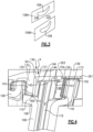
Figure 4 shows a challenge with re-staggering. Whenairfoil 108 is turned, thebaffle 115 must also turn. However, there is a common support structure for supporting the vane and the baffle. Thus, as shown in this Figure, amount structure 130 includes avane support 133 having aninner tab 135 moving into achamber 148 defined betweenwall 142, a riser, orwall 144 andbase 300 of a component known as abathtub seal 143. - A
riser 144 includes structure securing thebaffle 115 to thebathtub seal 143, as explained below. -
Mount structure 130 has aflange cap 154 also received within thechamber 148 of the bathtub seal.Flange cap 154 extends acrossvane mount structure 113 and a wall ofbathtub seal 143.Coatings 150 are formed between theflange cap 154 and themount structure 113.Flange cap 154 is formed of an appropriate metal, such as Haynes 188™. Themount structure 113 of thevane 106 is connected to thebathtub seal 143 throughflange cap 154 secured across anouter wall 142 of the bathtub seal and the mount structure. As can be appreciated, when the orientation of theairfoil 108 changes, the orientation of themount structure 113 will also change. This can be accommodated by machining away a portion of thecoating 150. However, there are challenges with accommodating the rotation of thebaffle 115 as thebathtub seal 143 is desirably in a common position for all of thevanes 106 to simply mounting. - As shown in
Figure 4 , there areopenings 201 and 200 through thesupport 133 into achamber 137. Opening 200 communicates with a source of air at a pressure, such as air from the compressor of an associated engine.Chamber 137 supplies air into anopening 197 at an outer end of thebaffle 115. This provides cooling air within thevane 106. - A
stop 203 is also illustrated holding a plurality ofshims 201.Shims 261 control a spacing between an inner wall of a secondvane supply support 139 and an upper end of themount structure 113. Theshims 201 include a plurality of shims which could be removed to control the clearance. - The
flange cap 154 extends across a wall ofbathtub seal 143 and themount structure 113. Thebathtub seal 143 also provides sealing with the vanes supporting hardware and is constrained and supported by the vane supporting hardware. - The
bathtub seal wall 142 seals against a side of anadjacent vane 106A via pressure loading and thermal expansion. - The
vertical wall 142 on the opposed side is trapped in a load path between themount structure 113 of thevane 106B and the support structure. This constraint provides sufficient loading to trap the baffle assembly within the load tap and seal against all mating surfaces, while still allowing the baffle to be cantilevered within the vane cavity and without fixing the baffle to the vane. - Details of this structure are betted disclosed and claimed in co-pending
United States patent application entitled "BATHTUB SEAL INTEGRATED INTO CMC VANE LOAD PATH," filed on August 21, 2024 by the Applicant of this application, and identified by Serial No. 18/452912 -
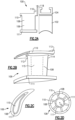
Figure 5A shows details of thebaffle 115. Thebathtub seal 143 is secured to the baffle. As can be appreciated, theriser 144 includesbathtub seal 143 having anupper support face 145 supporting anupper face 147 of thebaffle 115.Baffle 115 has coolingholes 160 for delivering air from aninternal chamber 162 into the chamber 117 (seeFigure 2C ). -
Figure 5B shows further detail of the connection between theupper face 147 and theupper face 145 ofbathtub seal 143. -
Figure 5C shows thebathtub seal 143 havingwalls upper support face 145. -
Figure 6 shows another feature of the disclosedbathtub seal 143. As can be seen, there is avane 106A with anadjacent vane 106B. Theplatform 110 of the vane is illustrated. As can be seen, thebathtub seal 143 has itsbase wall 300 covering the majority of a surface area of theplatform 110. There is asmall tab 310 at one circumferential end of the platform that is not covered. However, the overall surface area of theplatform 110 is at least 75% covered by thebase wall 300. As can be appreciated, the air moving intochamber 148 is at a higher pressure due to it being compressed. Thus, there is a pressure differential between a radially outer side of thebase wall 300 and a radially inner side. This provides a force pushing thebase wall 300 down into contact with theplatform 110. - A CMC vane, such as
vanes 106, can have relatively thin and unsupported platforms. Thus, they could be subject to potential modal excitation at various points in the running range of a gas turbine engine. Thebase wall 300 being biased into contact with theplatform 110 provides damping of this modal excitation. The areas of highest challenge are at the edges of the platform, and namely the leading edge, trailing edge, suction side and pressure side. Thus, ensuring coverage to be close to, if not at, each of those could be valuable. - Details of this feature are disclosed in copending
United States Patent Application, entitled "BATHTUB SEAL FOR DAMPING CMC VANE PLATFORM," filed on August 21, 2023 by the Applicant of this application, and identified as Serial No. 18/452922 - As shown in
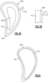
Figure 7A , in a method according to this invention, once it has been determined how much re-stagger a particular vane will require theupper face 147 is shifted accordingly relative to thesupport face 145. The twocomponents upper face 147 has been shifted, it is then brazed as shown schematically by abrazing tool 170. While brazing is specifically disclosed, the two pieces could be joined together via welding or other joining methods. Further, it could actually be locked in place by some mechanical locking method in some applications. Now, a common support structure can be utilized for thebathtub seal 143 by simply making each attachedbaffle 115 andbathtub seal 143 unique for the particular re-stagger angle. -
Figure 7B shows themount surface 113 on the vane having thecoating 150 with amachine 171 machining away thecoating 150 to also account for the re-stagger angle of the vane relative to the mount structure. - As shown in
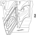
Figure 8 , a first orientation of anupper face 147 of thebaffle 115 is shown relative to theupper face 145 of the bathtub seal. Asecond orientation 161 of theupper face 147 is shown in phantom. As one can see, the relative positions will vary. The amount of variation may be somewhat exaggerated to show the existence. Thus, different vanes will have different orientations offace - When a metal turbine vane is utilized with a baffle, the baffle is typically fixed to the vane itself. Thus, if the vane airfoil is re-staggered, the baffle will rotate with the airfoil. However, a metal baffle cannot be joined to a CMC vane. The baffle needs to be supported by other hardware. The bathtub seal provides sealing with the vane supporting hardware and is constrained and supported by the vane supporting hardware. The bathtub seal also supports the baffle via the riser.
- A method of forming a vane assembly for a gas turbine engine under this disclosure could be said to include the steps of: 1) determining a re-stagger angle for an airfoil on a ceramic matrix composite ("CMC") vane, 2) determining an adjusted position of a baffle to be inserted within a central chamber in the vane, inserting the baffle into a bathtub seal, and adjusting an upper face of the baffle to an orientation relative to a bathtub seal support face to account for the adjusted position of the baffle and 3) fixing the baffle upper face to the bathtub seal flange support face.
- A vane assembly under this disclosure could be said to include a vane having an outer platform with mount structure and an airfoil extending inwardly from the mount structure and formed of ceramic matrix composites ("CMC"). The vane has an internal cooling chamber. A metal baffle is received within the cooling chamber and extends beyond the platform to a riser. The riser includes an upper face fixed to a bathtub seal at a bathtub seal support face, and an orientation of the upper face relative to the bathtub seal support face is adjusted to accommodate a re-stagger angle on the airfoil of the vane.
- A gas turbine engine under this disclosure could be said to include a compressor section, a combustor and a turbine section. The turbine section includes rotating blade rows alternating with static vane rows. The vane rows include a vane assembly having a plurality of vanes with an outer platform having mount structure and an airfoil extending inwardly from the mount structure and the vane formed of ceramic matrix composites ("CMC"). The vane has an internal cooling chamber. A metal baffle is received within the cooling chamber and extends beyond the platform to a riser. The riser includes an upper face fixed to a bathtub seal at a bathtub seal support face, and an orientation of the upper face relative to said bathtub seal support face being adjusted to accommodate a re-stagger angle on the airfoil of the vane.
- Although embodiments of this disclosure have been shown, a worker of ordinary skill in this art would recognize that modifications would come within the scope of this disclosure. For that reason, the following claims should be studied to determine the true scope and content of this disclosure.
Claims (15)
- A method of forming a vane assembly for a gas turbine engine (20) comprising the steps of:1) determining a re-stagger angle for an airfoil (108) on a ceramic matrix composite ("CMC") vane (106);2) determining an adjusted position of a baffle (115) to be inserted within a central chamber (117) in the vane (106), inserting the baffle (115) into a bathtub seal (143), and adjusting an upper face (147) of the baffle (115) to an orientation relative to a bathtub seal support face (145) to account for the adjusted position of the baffle (115); and3) fixing the baffle upper face (147) to the bathtub seal support face (145).
- The method as set forth in claim 1, wherein step 3) is performed by brazing.
- The method as set forth in claim 1 or 2, wherein the fixed bathtub seal (143) and baffle (115) are inserted into the central chamber (117) in the vane (106) and the vane (106) is then mounted into a vane row with the bathtub seal (143) providing support between the vane (106), the baffle (115) and static structure (130).
- The method as set forth in claim 3, wherein the static structure (130) includes a first vane support (133) having a tab (135) extending into a seal chamber (148) defined between an inner and an outer wall (144, 142) of the bathtub seal (143).
- The method as set forth in any preceding claim, wherein a mount structure (113) on an upper surface of a vane platform (110) is provided with a coating (150) on an outer surface, and further comprising adjusting the coating (150) to account for the re-stagger angle of the airfoil (108) and connecting the mount structure (113) on the vane (106) to the bathtub seal (143).
- The method as set forth in any preceding claim, wherein a/the mount structure (113) of the vane (106) is connected to the bathtub seal (143) through a flange cap (154) secured across the outer wall (142) of the bathtub seal (143) and the mount structure (113).
- The method as set forth in any preceding claim, including the steps of assembling a vane row of a plurality of the vanes (106) with at least a first vane (106A) having the airfoil (108) with a first re-stagger angle that is different relative to at least the airfoil (108) of a second of the plurality of vanes (106B) and the orientation of the baffle upper face (147) relative to the bathtub seal support face (145) is distinct between the first vane (106A) and the second vane (106B).
- A vane assembly comprising:a vane (106) having an outer platform (110) with mount structure (113, 116) and an airfoil (108) extending inwardly from the mount structure (113, 116) and formed of ceramic matrix composites ("CMC"), the vane (106) having an internal cooling chamber (117);a metal baffle (115) received within said internal cooling chamber (117) and extending beyond said platform (110) to an upper face (147) fixed to a bathtub seal (143) at a bathtub seal support face (145), and an orientation of said upper face (147) relative to said bathtub seal support face (145) being adjusted to accommodate a re-stagger angle on the airfoil (108) of the vane (106).
- The vane assembly as set forth in claim 8, wherein the upper face (147) and the support face (145) are brazed together.
- The vane assembly as set forth in claim 8 or 9, wherein the vane (106) is mounted into a vane row with the bathtub seal (143) providing support between the vane (106), the baffle (115) and static structure (130).
- The vane assembly as set forth in claim 10, wherein the static structure (130) includes a first vane support (133) having a tab (135) extending into a seal chamber (148) defined between an inner and an outer wall (144, 142) of the bathtub seal (143).
- The vane assembly as set forth in any of claims 8 to 11, wherein a mount structure (113) on an upper surface of a vane platform (110) is provided with a coating (150) on an outer surface, and/or wherein a flange cap (154) extends across a/the mount structure (113) of the vane (106) and across an/the outer wall (142) of the bathtub seal (143).
- The vane assembly as set forth in any of claims 8 to 12, including a vane row of a plurality of the vanes (106) with at least a first vane (106A) having the airfoil (108) with a first re-stagger angle that is different relative to at least the airfoil (108) of a second of the plurality of vanes (106B) and the orientation of the baffle upper face (147) relative to the bathtub seal support face (145) is distinct between the first vane (106A) and the second vane (106B).
- A gas turbine engine (20) comprising:
a compressor section (24), a combustor (56) and a turbine section (28; 100), the turbine section (100) including rotating blade rows alternating with static vane rows, and the vane rows including the vane assembly of any of claims 8 to 12, the vane assembly having a plurality of the vanes (106). - The gas turbine engine (20) as set forth in claim 14, wherein the plurality of the vanes (106) includes a first vane (106A) having an airfoil (108) with a first re-stagger angle that is different relative to at least the airfoil (108) of a second of the plurality of vanes (106B) and the orientation of the upper face (147) relative to the bathtub seal support face (145) is distinct between the first vane (106A) and the second vane (106B).
Applications Claiming Priority (1)
| Application Number | Priority Date | Filing Date | Title |
|---|---|---|---|
| US18/452,901 US12281597B2 (en) | 2023-08-21 | 2023-08-21 | CMC vane with rotatable baffle design to accommodate re-stagger |
Publications (1)
| Publication Number | Publication Date |
|---|---|
| EP4517050A1 true EP4517050A1 (en) | 2025-03-05 |
Family
ID=92503601
Family Applications (1)
| Application Number | Title | Priority Date | Filing Date |
|---|---|---|---|
| EP24195731.5A Pending EP4517050A1 (en) | 2023-08-21 | 2024-08-21 | Cmc vane with rotatable baffle design to accommodate re-stagger |
Country Status (2)
| Country | Link |
|---|---|
| US (1) | US12281597B2 (en) |
| EP (1) | EP4517050A1 (en) |
Families Citing this family (1)
| Publication number | Priority date | Publication date | Assignee | Title |
|---|---|---|---|---|
| US12509988B2 (en) | 2024-06-14 | 2025-12-30 | Pratt & Whitney Canada Corp. | Turbine engine airfoil |
Citations (3)
| Publication number | Priority date | Publication date | Assignee | Title |
|---|---|---|---|---|
| US5630700A (en) * | 1996-04-26 | 1997-05-20 | General Electric Company | Floating vane turbine nozzle |
| US20170081966A1 (en) * | 2015-09-18 | 2017-03-23 | General Electric Company | Stator component cooling |
| US20220082024A1 (en) * | 2020-09-17 | 2022-03-17 | Raytheon Technologies Corporation | Cmc vane with support spar and baffle |
Family Cites Families (24)
| Publication number | Priority date | Publication date | Assignee | Title |
|---|---|---|---|---|
| US3301527A (en) | 1965-05-03 | 1967-01-31 | Gen Electric | Turbine diaphragm structure |
| US5145315A (en) * | 1991-09-27 | 1992-09-08 | Westinghouse Electric Corp. | Gas turbine vane cooling air insert |
| US6019572A (en) | 1998-08-06 | 2000-02-01 | Siemens Westinghouse Power Corporation | Gas turbine row #1 steam cooled vane |
| US6382906B1 (en) | 2000-06-16 | 2002-05-07 | General Electric Company | Floating spoolie cup impingement baffle |
| US6464456B2 (en) | 2001-03-07 | 2002-10-15 | General Electric Company | Turbine vane assembly including a low ductility vane |
| US8393867B2 (en) * | 2008-03-31 | 2013-03-12 | United Technologies Corporation | Chambered airfoil cooling |
| US8251652B2 (en) | 2008-09-18 | 2012-08-28 | Siemens Energy, Inc. | Gas turbine vane platform element |
| JP2012246785A (en) | 2011-05-25 | 2012-12-13 | Mitsubishi Heavy Ind Ltd | Gas turbine stator vane |
| US20130004320A1 (en) * | 2011-06-28 | 2013-01-03 | United Technologies Corporation | Method of rotated airfoils |
| US20170198602A1 (en) * | 2016-01-11 | 2017-07-13 | General Electric Company | Gas turbine engine with a cooled nozzle segment |
| JP6651378B2 (en) | 2016-02-22 | 2020-02-19 | 三菱日立パワーシステムズ株式会社 | Insert assembly, blade, gas turbine, and method of manufacturing blade |
| US10794289B2 (en) * | 2016-08-09 | 2020-10-06 | General Electric Company | Modulated turbine component cooling |
| US10774665B2 (en) | 2018-07-31 | 2020-09-15 | General Electric Company | Vertically oriented seal system for gas turbine vanes |
| US11702941B2 (en) * | 2018-11-09 | 2023-07-18 | Raytheon Technologies Corporation | Airfoil with baffle having flange ring affixed to platform |
| US10774657B2 (en) | 2018-11-23 | 2020-09-15 | Raytheon Technologies Corporation | Baffle assembly for gas turbine engine components |
| US11473444B2 (en) | 2019-11-08 | 2022-10-18 | Raytheon Technologies Corporation | Ceramic airfoil with cooling air turn |
| US11346234B2 (en) | 2020-01-02 | 2022-05-31 | Rolls-Royce Plc | Turbine vane assembly incorporating ceramic matrix composite materials |
| US12359622B2 (en) * | 2020-04-09 | 2025-07-15 | Rtx Corporation | Vane support system |
| US11203981B1 (en) | 2020-08-06 | 2021-12-21 | Raytheon Technologies Corporation | Baffle systems for airfoils |
| US11486256B2 (en) | 2020-12-07 | 2022-11-01 | Raytheon Technologies Corporation | Vane arc segment with conformal thermal insulation blanket |
| US11454129B1 (en) | 2021-04-02 | 2022-09-27 | Raytheon Technologies Corporation | CMC component flow discourager flanges |
| US11643932B2 (en) * | 2021-04-30 | 2023-05-09 | General Electric Company | Compressor rotor blade airfoils |
| US11773735B2 (en) | 2021-12-22 | 2023-10-03 | Rolls-Royce Plc | Vane ring assembly with ceramic matrix composite airfoils |
| EP4469662A1 (en) | 2022-01-28 | 2024-12-04 | RTX Corporation | Cooled vane with forward rail for gas turbine engine |
-
2023
- 2023-08-21 US US18/452,901 patent/US12281597B2/en active Active
-
2024
- 2024-08-21 EP EP24195731.5A patent/EP4517050A1/en active Pending
Patent Citations (3)
| Publication number | Priority date | Publication date | Assignee | Title |
|---|---|---|---|---|
| US5630700A (en) * | 1996-04-26 | 1997-05-20 | General Electric Company | Floating vane turbine nozzle |
| US20170081966A1 (en) * | 2015-09-18 | 2017-03-23 | General Electric Company | Stator component cooling |
| US20220082024A1 (en) * | 2020-09-17 | 2022-03-17 | Raytheon Technologies Corporation | Cmc vane with support spar and baffle |
Also Published As
| Publication number | Publication date |
|---|---|
| US12281597B2 (en) | 2025-04-22 |
| US20250067185A1 (en) | 2025-02-27 |
Similar Documents
| Publication | Publication Date | Title |
|---|---|---|
| US12607129B2 (en) | Attachment region for CMC components | |
| EP3971391B1 (en) | Cmc vane for a gas turbine engine with support and impingement baffle | |
| EP4350126B1 (en) | Blade outer air seal cooling arrangement | |
| EP3461993B1 (en) | Gas turbine engine blade | |
| EP4513000A1 (en) | Bathtub seal for damping cmc vane platform | |
| US12281597B2 (en) | CMC vane with rotatable baffle design to accommodate re-stagger | |
| US20250230751A1 (en) | Turbine blade with boomerang shaped wall cooling passages | |
| EP4353949B1 (en) | Gas turbine engine vane and spar combination with variable air flow path | |
| EP4379190B1 (en) | Removable layer to adjust mount structure of a turbine vane for re-stagger | |
| EP4345256B1 (en) | Gas turbine engine and gas turbine engine component | |
| EP4517049A1 (en) | Bathtub seal integrated into cmc vane load path | |
| EP4549701B1 (en) | Combined gas turbine engine vane and blade outer air seal assembly and gas turbine engine | |
| EP4293197A1 (en) | Component for a gas turbine engine and gas turbine engine | |
| US12258867B1 (en) | Attachment for blade outer air seal | |
| EP4361405A1 (en) | Gas turbine engine turbine section with axial seal | |
| US12448708B2 (en) | Extended inner profile for mandrel for use in forming braided CMC structures | |
| EP4596833A1 (en) | Load bearing feature for ceramic matrix composite turbine components | |
| EP4417788A1 (en) | Gas turbine engine blade and method of sizing a damper for a gas turbine engine blade | |
| US12012870B1 (en) | Machinable coating for CMC and metal interface in a turbine section | |
| US20260139600A1 (en) | Machinable coating for damping |
Legal Events
| Date | Code | Title | Description |
|---|---|---|---|
| PUAI | Public reference made under article 153(3) epc to a published international application that has entered the european phase |
Free format text: ORIGINAL CODE: 0009012 |
|
| STAA | Information on the status of an ep patent application or granted ep patent |
Free format text: STATUS: THE APPLICATION HAS BEEN PUBLISHED |
|
| AK | Designated contracting states |
Kind code of ref document: A1 Designated state(s): AL AT BE BG CH CY CZ DE DK EE ES FI FR GB GR HR HU IE IS IT LI LT LU LV MC ME MK MT NL NO PL PT RO RS SE SI SK SM TR |
|
| STAA | Information on the status of an ep patent application or granted ep patent |
Free format text: STATUS: REQUEST FOR EXAMINATION WAS MADE |
|
| 17P | Request for examination filed |
Effective date: 20250905 |