EP4517046A1 - Nose cone/spinner power takeoff - Google Patents
Nose cone/spinner power takeoff Download PDFInfo
- Publication number
- EP4517046A1 EP4517046A1 EP24197163.9A EP24197163A EP4517046A1 EP 4517046 A1 EP4517046 A1 EP 4517046A1 EP 24197163 A EP24197163 A EP 24197163A EP 4517046 A1 EP4517046 A1 EP 4517046A1
- Authority
- EP
- European Patent Office
- Prior art keywords
- coupling
- fan hub
- auxiliary unit
- fan
- gas turbine
- Prior art date
- Legal status (The legal status is an assumption and is not a legal conclusion. Google has not performed a legal analysis and makes no representation as to the accuracy of the status listed.)
- Pending
Links
Images
Classifications
-
- F—MECHANICAL ENGINEERING; LIGHTING; HEATING; WEAPONS; BLASTING
- F01—MACHINES OR ENGINES IN GENERAL; ENGINE PLANTS IN GENERAL; STEAM ENGINES
- F01D—NON-POSITIVE DISPLACEMENT MACHINES OR ENGINES, e.g. STEAM TURBINES
- F01D5/00—Blades; Blade-carrying members; Heating, heat-insulating, cooling or antivibration means on the blades or the members
- F01D5/02—Blade-carrying members, e.g. rotors
- F01D5/026—Shaft to shaft connections
-
- F—MECHANICAL ENGINEERING; LIGHTING; HEATING; WEAPONS; BLASTING
- F02—COMBUSTION ENGINES; HOT-GAS OR COMBUSTION-PRODUCT ENGINE PLANTS
- F02C—GAS-TURBINE PLANTS; AIR INTAKES FOR JET-PROPULSION PLANTS; CONTROLLING FUEL SUPPLY IN AIR-BREATHING JET-PROPULSION PLANTS
- F02C7/00—Features, components parts, details or accessories, not provided for in, or of interest apart form groups F02C1/00 - F02C6/00; Air intakes for jet-propulsion plants
- F02C7/32—Arrangement, mounting, or driving, of auxiliaries
-
- F—MECHANICAL ENGINEERING; LIGHTING; HEATING; WEAPONS; BLASTING
- F02—COMBUSTION ENGINES; HOT-GAS OR COMBUSTION-PRODUCT ENGINE PLANTS
- F02C—GAS-TURBINE PLANTS; AIR INTAKES FOR JET-PROPULSION PLANTS; CONTROLLING FUEL SUPPLY IN AIR-BREATHING JET-PROPULSION PLANTS
- F02C7/00—Features, components parts, details or accessories, not provided for in, or of interest apart form groups F02C1/00 - F02C6/00; Air intakes for jet-propulsion plants
- F02C7/36—Power transmission arrangements between the different shafts of the gas turbine plant, or between the gas-turbine plant and the power user
-
- F—MECHANICAL ENGINEERING; LIGHTING; HEATING; WEAPONS; BLASTING
- F02—COMBUSTION ENGINES; HOT-GAS OR COMBUSTION-PRODUCT ENGINE PLANTS
- F02K—JET-PROPULSION PLANTS
- F02K3/00—Plants including a gas turbine driving a compressor or a ducted fan
- F02K3/02—Plants including a gas turbine driving a compressor or a ducted fan in which part of the working fluid by-passes the turbine and combustion chamber
- F02K3/04—Plants including a gas turbine driving a compressor or a ducted fan in which part of the working fluid by-passes the turbine and combustion chamber the plant including ducted fans, i.e. fans with high volume, low pressure outputs, for augmenting the jet thrust, e.g. of double-flow type
- F02K3/06—Plants including a gas turbine driving a compressor or a ducted fan in which part of the working fluid by-passes the turbine and combustion chamber the plant including ducted fans, i.e. fans with high volume, low pressure outputs, for augmenting the jet thrust, e.g. of double-flow type with front fan
-
- F—MECHANICAL ENGINEERING; LIGHTING; HEATING; WEAPONS; BLASTING
- F04—POSITIVE - DISPLACEMENT MACHINES FOR LIQUIDS; PUMPS FOR LIQUIDS OR ELASTIC FLUIDS
- F04D—NON-POSITIVE-DISPLACEMENT PUMPS
- F04D29/00—Details, component parts, or accessories
- F04D29/26—Rotors specially for elastic fluids
- F04D29/32—Rotors specially for elastic fluids for axial flow pumps
- F04D29/325—Rotors specially for elastic fluids for axial flow pumps for axial flow fans
- F04D29/329—Details of the hub
-
- F—MECHANICAL ENGINEERING; LIGHTING; HEATING; WEAPONS; BLASTING
- F05—INDEXING SCHEMES RELATING TO ENGINES OR PUMPS IN VARIOUS SUBCLASSES OF CLASSES F01-F04
- F05D—INDEXING SCHEME FOR ASPECTS RELATING TO NON-POSITIVE-DISPLACEMENT MACHINES OR ENGINES, GAS-TURBINES OR JET-PROPULSION PLANTS
- F05D2220/00—Application
- F05D2220/30—Application in turbines
- F05D2220/36—Application in turbines specially adapted for the fan of turbofan engines
-
- F—MECHANICAL ENGINEERING; LIGHTING; HEATING; WEAPONS; BLASTING
- F05—INDEXING SCHEMES RELATING TO ENGINES OR PUMPS IN VARIOUS SUBCLASSES OF CLASSES F01-F04
- F05D—INDEXING SCHEME FOR ASPECTS RELATING TO NON-POSITIVE-DISPLACEMENT MACHINES OR ENGINES, GAS-TURBINES OR JET-PROPULSION PLANTS
- F05D2260/00—Function
- F05D2260/40—Transmission of power
Definitions
- the present disclosure is directed to a coupling for use on a fan rotor.
- One solution for increasing the available power is to modify the Airframe Mounted Accessory Drive (AMAD) to provide more power and install a larger generator on the AMAD.
- Another solution is to modify the Engine Mounted Accessory Drive (EMAD).
- AMAD Airframe Mounted Accessory Drive
- EEMAD Engine Mounted Accessory Drive
- these solutions are difficult to achieve for at least two reasons: (1) no empty volume exists within the aircraft for a larger generator and AMAD or EMAD to grow into, and (2) changing the AMAD or EMAD and generator is cost prohibitive.
- Other options, however, are typically less attractive or not feasible for various reasons. For instance, a pop-up air scoop could be deployed to drive a Ram Air Turbine (RAT) that would drive a generator.
- RAT Ram Air Turbine
- the additional aerodynamic drag could adversely affect aircraft performance.
- the additional RAT incurs a large amount of weight and mechanical complexity compared to the amount of extra power generated so that it is inefficient from both a cost and energy standpoint.
- Gas turbine engines include a fan with a fan hub or rotor supporting fan blades.
- the forward portion of the fan hub can include a nose cone.
- the nose cone can be removeable.
- the removable nose cone can be fastened by a set of nose cone fasteners.
- a coupling for a fan hub comprising an auxiliary unit attached to the coupling; the fan hub attached to the coupling opposite the auxiliary unit, wherein the coupling is configured to translate rotary motion along an axis from the fan hub to the auxiliary unit to provide rotational power from a gas turbine engine to the auxiliary unit.
- Particular embodiments further may include at least one, or a plurality of, the following optional features, alone or in combination with each other:
- a further embodiment of any of the foregoing embodiments may additionally and/or alternatively include the fan hub supports fan blades.
- a further embodiment of any of the foregoing embodiments may additionally and/or alternatively include the auxiliary unit is selected from the group consisting of an electrical generator, a hydraulic pump and an airframe mounted accessory drive.
- a further embodiment of any of the foregoing embodiments may additionally and/or alternatively include the coupling comprises a drive adapter having a coupling bolt pattern for attaching to the fan hub.
- a further embodiment of any of the foregoing embodiments may additionally and/or alternatively include the coupling comprises a flexible member attached to the drive adapter.
- a further embodiment of any of the foregoing embodiments may additionally and/or alternatively include the flexible member comprises laminated sheets located on opposite sides of a central shaft.
- a further embodiment of any of the foregoing embodiments may additionally and/or alternatively include the coupling comprises a bearing system attached to the flexible member opposite the drive adapter.
- a gas turbine engine coupling for a fan hub power takeoff comprising a fan located at a forward portion of the gas turbine engine, the fan comprising the fan hub supporting fan blades; a casing attached forward of the fan proximate the forward portion of the gas turbine engine; an auxiliary unit mounted in the casing; a coupling operatively coupled between the fan hub and the auxiliary unit, wherein the coupling is configured to translate rotary motion along an axis from the fan hub to the auxiliary unit to provide rotational power from the gas turbine engine to the auxiliary unit.
- a further embodiment of any of the foregoing embodiments may additionally and/or alternatively include the coupling comprises a drive adapter having a coupling bolt pattern for attaching to a fan hub flange bolt pattern to secure the drive adapter to the fan hub.
- a further embodiment of any of the foregoing embodiments may additionally and/or alternatively include the coupling comprises a flexible member attached to the drive adapter configured to dampen misalignment between the fan hub and the auxiliary unit.
- a further embodiment of any of the foregoing embodiments may additionally and/or alternatively include the flexible member comprises laminated sheets located on opposite sides of a central shaft.
- a further embodiment of any of the foregoing embodiments may additionally and/or alternatively include the coupling comprises a bearing system attached to the flexible member opposite the drive adapter, the bearing system comprising a duplex bearing.
- a further embodiment of any of the foregoing embodiments may additionally and/or alternatively include the coupling comprises a spline interface mounted between the duplex bearing and a drive shaft of the auxiliary unit.
- a process for employing a gas turbine engine coupling for a fan hub power takeoff comprising locating a fan at a forward portion of the gas turbine engine, the fan comprising the fan hub supporting fan blades; attaching a casing forward of the fan proximate the forward portion of the gas turbine engine; mounting an auxiliary unit in the casing; attaching a coupling between the fan hub and the auxiliary unit; and translating rotary motion along an axis from the fan hub to the auxiliary unit to provide rotational power from the gas turbine engine to the auxiliary unit.
- Particular embodiments further may include at least one, or a plurality of, the following optional features, alone or in combination with each other:
- a further embodiment of any of the foregoing embodiments may additionally and/or alternatively include the process further comprising attaching the coupling to the fan hub employing a drive adapter having a coupling bolt pattern configured to match a bolt pattern of a fan hub flange bolt pattern to secure the drive adapter to the fan hub.
- a further embodiment of any of the foregoing embodiments may additionally and/or alternatively include the process further comprising attaching a flexible member to the drive adapter; dampening misalignment between the fan hub and the auxiliary unit employing the flexible member.
- a further embodiment of any of the foregoing embodiments may additionally and/or alternatively include the process further comprising attaching a bearing system to the flexible member opposite the drive adapter, the bearing system comprising a duplex bearing; and dampening rotational whirl with the duplex bearing.
- a further embodiment of any of the foregoing embodiments may additionally and/or alternatively include the process further comprising mounting a spline interface between the duplex bearing and a drive shaft of the auxiliary unit.
- a further embodiment of any of the foregoing embodiments may additionally and/or alternatively include the process further comprising supporting the bearing system with a bearing support attached to a centerbody of the casing.
- a further embodiment of any of the foregoing embodiments may additionally and/or alternatively include the auxiliary unit is selected from the group consisting of an electrical generator, a hydraulic pump and an airframe mounted accessory drive.
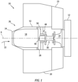
- Fig. 1 is a schematic representation of a gas turbine engine forward portion.
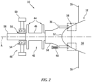
- Fig. 2 is a schematic representation of an exemplary coupling for a fan hub.
- the gas turbine engine 10 includes a fan 12.
- the fan 12 includes a fan hub 14 supporting fan blades 16.
- the gas turbine engine 10 includes an auxiliary unit 18.
- the auxiliary unit 18 can be an electrical generator or a hydraulic pump or other form of airframe or engine mounted accessory.
- the auxiliary unit 18 can be housed within a case 20.
- the case 20 provides structural support via support 23 to the auxiliary unit 18 as well as aerodynamic function for managing air flow 22 through the auxiliary unit 18 and fan 12.
- a nose cone 24 is mounted on a case forward portion 26 of the case 20.
- the nose cone 24 can manage the air flow 22 into or around the auxiliary unit 18.
- a mount ring 28 can be employed to secure the auxiliary unit 18 to the case 20.
- a coupling 30 can operably couple the fan hub 14 and the auxiliary unit 18 so that rotary motion can be translated along Axis A from the fan hub 14 to the auxiliary unit 18 to provide rotational power from the gas turbine engine 10 to the auxiliary unit 18.
- a removeable fan spinner/nose cone 32 can be replaced to allow for the coupling 30 to attach with the fan hub 14.
- the coupling 30 can include a drive adapter 34.
- the drive adapter 34 includes a coupling bolt pattern 36 that matches a fan hub flange 38 bolt pattern to secure the drive adapter 34 to the fan hub 14.
- the fan nose cone 32 can be removed to provide an interface for the coupling 30.
- the fan nose cone 32 is attached to the fan hub flange 38.
- Spinner bolts 40 can be removed from the fan hub flange 38.
- the fan nose cone 32 can be removed from the fan hub flange 38.
- the drive adaptor 34 can be bolted to the fan hub flange 38 to secure the coupling 30 to the fan hub 14.
- the coupling 30 includes a flexible member 42 attached to the drive adapter 34.
- the flexible member 42 is configured to dampen misalignment between the fan hub 14 and the auxiliary unit 18.
- the flexible member 42 can include laminated sheets 44 located on opposite sides of a central shaft 46.
- the laminated sheets 44 can be constructed from stainless steel sheets.
- the flexible member 42 can be rigid in response to torsional forces while remaining flexible in response to axial forces.
- the coupling 30 includes a bearing system 48 attached to the flexible member 42 opposite the drive adapter 34.
- the bearing system 48 supports the coupling 30 via a bearing support 50.
- the bearing support 50 can be attached to a centerbody 52 of the case 20.
- the bearing system 48 includes a duplex bearing 54.
- the duplex bearing 54 is configured to dampen rotational whirl.
- a spline interface 56 is mounted between the duplex bearing 54 and a drive shaft 58 of the auxiliary unit 18.
- the use of the bearing system 48 allows for the drive shaft 58 of the auxiliary unit to be relatively rigid.
- a technical advantage of the disclosed nose cone spinner/power takeoff can include that the engine remains BOM with the addition of the power take-off shaft.
- Another technical advantage of the disclosed nose cone spinner/power takeoff can include the power take-off shaft becomes interchangeable with no need for a recertification of the engine.
- Another technical advantage of the disclosed nose cone spinner/power takeoff can include powering an auxiliary unit via the low spool.
- Another technical advantage of the disclosed nose cone spinner/power takeoff can include the capacity to significantly increase the electrical power to an aircraft with minimal redesign.
Landscapes
- Engineering & Computer Science (AREA)
- Chemical & Material Sciences (AREA)
- Combustion & Propulsion (AREA)
- Mechanical Engineering (AREA)
- General Engineering & Computer Science (AREA)
- Structures Of Non-Positive Displacement Pumps (AREA)
Abstract
A coupling (30) for a fan hub (14) including an auxiliary unit (18) attached to the coupling; the fan hub attached to the coupling opposite the auxiliary unit, wherein the misalignment-tolerant coupling is configured to translate rotary motion along an axis from the fan hub to the auxiliary unit to provide rotational power from a gas turbine engine (10) to the auxiliary unit.
Description
- The present disclosure is directed to a coupling for use on a fan rotor.
- Certain aircraft lack sufficient electrical power to run current electronic systems, for example, for avionics systems. One solution for increasing the available power is to modify the Airframe Mounted Accessory Drive (AMAD) to provide more power and install a larger generator on the AMAD. Another solution is to modify the Engine Mounted Accessory Drive (EMAD). Usually these solutions are difficult to achieve for at least two reasons: (1) no empty volume exists within the aircraft for a larger generator and AMAD or EMAD to grow into, and (2) changing the AMAD or EMAD and generator is cost prohibitive. Other options, however, are typically less attractive or not feasible for various reasons. For instance, a pop-up air scoop could be deployed to drive a Ram Air Turbine (RAT) that would drive a generator. This solution, imposes additional aerodynamic drag on the aircraft. The additional aerodynamic drag could adversely affect aircraft performance. The additional RAT incurs a large amount of weight and mechanical complexity compared to the amount of extra power generated so that it is inefficient from both a cost and energy standpoint.
- Gas turbine engines include a fan with a fan hub or rotor supporting fan blades. The forward portion of the fan hub can include a nose cone. In certain fan hub designs, the nose cone can be removeable. The removable nose cone can be fastened by a set of nose cone fasteners.
- What is needed is an alternative source of auxiliary power for a gas turbine engine without the unwanted drawbacks of modification of an AMAD or EMAD.
- In accordance with the present disclosure, there is provided a coupling for a fan hub comprising an auxiliary unit attached to the coupling; the fan hub attached to the coupling opposite the auxiliary unit, wherein the coupling is configured to translate rotary motion along an axis from the fan hub to the auxiliary unit to provide rotational power from a gas turbine engine to the auxiliary unit.
- Particular embodiments further may include at least one, or a plurality of, the following optional features, alone or in combination with each other:
- A further embodiment of any of the foregoing embodiments may additionally and/or alternatively include the fan hub supports fan blades.
- A further embodiment of any of the foregoing embodiments may additionally and/or alternatively include the auxiliary unit is selected from the group consisting of an electrical generator, a hydraulic pump and an airframe mounted accessory drive.
- A further embodiment of any of the foregoing embodiments may additionally and/or alternatively include the coupling comprises a drive adapter having a coupling bolt pattern for attaching to the fan hub.
- A further embodiment of any of the foregoing embodiments may additionally and/or alternatively include the coupling comprises a flexible member attached to the drive adapter.
- A further embodiment of any of the foregoing embodiments may additionally and/or alternatively include the flexible member comprises laminated sheets located on opposite sides of a central shaft.
- A further embodiment of any of the foregoing embodiments may additionally and/or alternatively include the coupling comprises a bearing system attached to the flexible member opposite the drive adapter.
- In accordance with the present disclosure, there is provided a gas turbine engine coupling for a fan hub power takeoff comprising a fan located at a forward portion of the gas turbine engine, the fan comprising the fan hub supporting fan blades; a casing attached forward of the fan proximate the forward portion of the gas turbine engine; an auxiliary unit mounted in the casing; a coupling operatively coupled between the fan hub and the auxiliary unit, wherein the coupling is configured to translate rotary motion along an axis from the fan hub to the auxiliary unit to provide rotational power from the gas turbine engine to the auxiliary unit.
- Particular embodiments further may include at least one, or a plurality of, the following optional features, alone or in combination with each other:
- A further embodiment of any of the foregoing embodiments may additionally and/or alternatively include the coupling comprises a drive adapter having a coupling bolt pattern for attaching to a fan hub flange bolt pattern to secure the drive adapter to the fan hub.
- A further embodiment of any of the foregoing embodiments may additionally and/or alternatively include the coupling comprises a flexible member attached to the drive adapter configured to dampen misalignment between the fan hub and the auxiliary unit.
- A further embodiment of any of the foregoing embodiments may additionally and/or alternatively include the flexible member comprises laminated sheets located on opposite sides of a central shaft.
- A further embodiment of any of the foregoing embodiments may additionally and/or alternatively include the coupling comprises a bearing system attached to the flexible member opposite the drive adapter, the bearing system comprising a duplex bearing.
- A further embodiment of any of the foregoing embodiments may additionally and/or alternatively include the coupling comprises a spline interface mounted between the duplex bearing and a drive shaft of the auxiliary unit.
- In accordance with the present disclosure, there is provided a process for employing a gas turbine engine coupling for a fan hub power takeoff comprising locating a fan at a forward portion of the gas turbine engine, the fan comprising the fan hub supporting fan blades; attaching a casing forward of the fan proximate the forward portion of the gas turbine engine; mounting an auxiliary unit in the casing; attaching a coupling between the fan hub and the auxiliary unit; and translating rotary motion along an axis from the fan hub to the auxiliary unit to provide rotational power from the gas turbine engine to the auxiliary unit.
- Particular embodiments further may include at least one, or a plurality of, the following optional features, alone or in combination with each other:
- A further embodiment of any of the foregoing embodiments may additionally and/or alternatively include the process further comprising attaching the coupling to the fan hub employing a drive adapter having a coupling bolt pattern configured to match a bolt pattern of a fan hub flange bolt pattern to secure the drive adapter to the fan hub.
- A further embodiment of any of the foregoing embodiments may additionally and/or alternatively include the process further comprising attaching a flexible member to the drive adapter; dampening misalignment between the fan hub and the auxiliary unit employing the flexible member.
- A further embodiment of any of the foregoing embodiments may additionally and/or alternatively include the process further comprising attaching a bearing system to the flexible member opposite the drive adapter, the bearing system comprising a duplex bearing; and dampening rotational whirl with the duplex bearing.
- A further embodiment of any of the foregoing embodiments may additionally and/or alternatively include the process further comprising mounting a spline interface between the duplex bearing and a drive shaft of the auxiliary unit.
- A further embodiment of any of the foregoing embodiments may additionally and/or alternatively include the process further comprising supporting the bearing system with a bearing support attached to a centerbody of the casing.
- A further embodiment of any of the foregoing embodiments may additionally and/or alternatively include the auxiliary unit is selected from the group consisting of an electrical generator, a hydraulic pump and an airframe mounted accessory drive.
- Other details of the coupling for a fan hub are set forth in the following detailed description and the accompanying drawings wherein like reference numerals depict like elements.
-
Fig. 1 is a schematic representation of a gas turbine engine forward portion. -
Fig. 2 is a schematic representation of an exemplary coupling for a fan hub. - Referring now to
Fig. 1 andFig. 2 , there is illustrated a forward portion of agas turbine engine 10. Thegas turbine engine 10 includes afan 12. Thefan 12 includes afan hub 14 supportingfan blades 16. - The
gas turbine engine 10 includes anauxiliary unit 18. Theauxiliary unit 18 can be an electrical generator or a hydraulic pump or other form of airframe or engine mounted accessory. Theauxiliary unit 18 can be housed within acase 20. Thecase 20 provides structural support viasupport 23 to theauxiliary unit 18 as well as aerodynamic function for managingair flow 22 through theauxiliary unit 18 andfan 12. Anose cone 24 is mounted on a caseforward portion 26 of thecase 20. Thenose cone 24 can manage theair flow 22 into or around theauxiliary unit 18. Amount ring 28 can be employed to secure theauxiliary unit 18 to thecase 20. - A
coupling 30 can operably couple thefan hub 14 and theauxiliary unit 18 so that rotary motion can be translated along Axis A from thefan hub 14 to theauxiliary unit 18 to provide rotational power from thegas turbine engine 10 to theauxiliary unit 18. - As seen in
Fig. 2 , a removeable fan spinner/nose cone 32 can be replaced to allow for thecoupling 30 to attach with thefan hub 14. Thecoupling 30 can include adrive adapter 34. Thedrive adapter 34 includes acoupling bolt pattern 36 that matches afan hub flange 38 bolt pattern to secure thedrive adapter 34 to thefan hub 14. Thefan nose cone 32 can be removed to provide an interface for thecoupling 30. Thefan nose cone 32 is attached to thefan hub flange 38.Spinner bolts 40 can be removed from thefan hub flange 38. Thefan nose cone 32 can be removed from thefan hub flange 38. Thedrive adaptor 34 can be bolted to thefan hub flange 38 to secure thecoupling 30 to thefan hub 14. - The
coupling 30 includes aflexible member 42 attached to thedrive adapter 34. Theflexible member 42 is configured to dampen misalignment between thefan hub 14 and theauxiliary unit 18. Theflexible member 42 can include laminatedsheets 44 located on opposite sides of acentral shaft 46. In an exemplary embodiment, the laminatedsheets 44 can be constructed from stainless steel sheets. Theflexible member 42 can be rigid in response to torsional forces while remaining flexible in response to axial forces. - The
coupling 30 includes abearing system 48 attached to theflexible member 42 opposite thedrive adapter 34. The bearingsystem 48 supports thecoupling 30 via abearing support 50. The bearingsupport 50 can be attached to acenterbody 52 of thecase 20. The bearingsystem 48 includes aduplex bearing 54. Theduplex bearing 54 is configured to dampen rotational whirl. - A
spline interface 56 is mounted between the duplex bearing 54 and adrive shaft 58 of theauxiliary unit 18. The use of the bearingsystem 48 allows for thedrive shaft 58 of the auxiliary unit to be relatively rigid. - A technical advantage of the disclosed nose cone spinner/power takeoff can include that the engine remains BOM with the addition of the power take-off shaft.
- Another technical advantage of the disclosed nose cone spinner/power takeoff can include the power take-off shaft becomes interchangeable with no need for a recertification of the engine.
- Another technical advantage of the disclosed nose cone spinner/power takeoff can include powering an auxiliary unit via the low spool.
- Another technical advantage of the disclosed nose cone spinner/power takeoff can include the capacity to significantly increase the electrical power to an aircraft with minimal redesign.
- There has been provided a coupling for a fan hub. While the coupling for a fan hub has been described in the context of specific embodiments thereof, other unforeseen alternatives, modifications, and variations may become apparent to those skilled in the art having read the foregoing description. Accordingly, it is intended to embrace those alternatives, modifications, and variations which fall within the broad scope of the appended claims.
Claims (15)
- A coupling for a fan hub comprising:an auxiliary unit attached to the coupling;the fan hub attached to the coupling opposite the auxiliary unit, wherein the coupling is configured to translate rotary motion along an axis from the fan hub to the auxiliary unit to provide rotational power from a gas turbine engine to the auxiliary unit.
- The coupling for a fan hub according to claim 1, wherein the fan hub supports fan blades.
- The coupling for a fan hub according to claim 1 or 2, wherein the auxiliary unit is selected from the group consisting of an electrical generator, a hydraulic pump and an airframe mounted accessory drive.
- The coupling for a fan hub according to any of claims 1 to 3, wherein the coupling comprises a drive adapter having a coupling bolt pattern for attaching to the fan hub.
- The coupling for a fan hub according to claim 4, wherein the coupling comprises a flexible member attached to the drive adapter.
- The coupling for a fan hub according to claim 5, wherein the flexible member comprises laminated sheets located on opposite sides of a central shaft.
- The coupling for a fan hub according to claim 5 or 6, wherein the coupling comprises a bearing system attached to the flexible member opposite the drive adapter.
- A gas turbine engine coupling for a fan hub power takeoff comprising:a fan located at a forward portion of the gas turbine engine, the fan comprising the fan hub supporting fan blades;a casing attached forward of the fan proximate the forward portion of the gas turbine engine; andthe coupling for a fan hub according to any of claims 1 to 7,wherein the auxiliary unit is mounted in the casing;wherein the coupling is operatively coupled between the fan hub and the auxiliary unit, wherein the coupling is configured to translate rotary motion along an axis from the fan hub to the auxiliary unit to provide rotational power from the gas turbine engine to the auxiliary unit.
- The gas turbine engine coupling for a fan hub power takeoff according to claim 8, wherein the coupling comprises a drive adapter having a coupling bolt pattern for attaching to a fan hub flange bolt pattern to secure the drive adapter to the fan hub;wherein particularly the coupling comprises a flexible member attached to the drive adapter configured to dampen misalignment between the fan hub and the auxiliary unit;wherein particularly the flexible member comprises laminated sheets located on opposite sides of a central shaft;wherein particularly the coupling comprises a bearing system attached to the flexible member opposite the drive adapter, the bearing system comprising a duplex bearing.
- The gas turbine engine coupling for a fan hub power takeoff according to claim 9, wherein the coupling comprises a spline interface mounted between the duplex bearing and a drive shaft of the auxiliary unit.
- A process for employing a gas turbine engine coupling for a fan hub power takeoff comprising:locating a fan at a forward portion of the gas turbine engine, the fan comprising the fan hub supporting fan blades;attaching a casing forward of the fan proximate the forward portion of the gas turbine engine;mounting an auxiliary unit in the casing;attaching a coupling between the fan hub and the auxiliary unit; andtranslating rotary motion along an axis from the fan hub to the auxiliary unit to provide rotational power from the gas turbine engine to the auxiliary unit.
- The process of claim 11, further comprising:
attaching the coupling to the fan hub employing a drive adapter having a coupling bolt pattern configured to match a bolt pattern of a fan hub flange bolt pattern to secure the drive adapter to the fan hub. - The process of claim 11 or 12, further comprising:attaching a flexible member to the drive adapter; anddampening misalignment between the fan hub and the auxiliary unit employing the flexible member;particularly further comprising:attaching a bearing system to the flexible member opposite the drive adapter, the bearing system comprising a duplex bearing; anddampening rotational whirl with the duplex bearing.
- The process of claim 13, further comprising:mounting a spline interface between the duplex bearing and a drive shaft of the auxiliary unit; and/orfurther comprising:
supporting the bearing system with a bearing support attached to a centerbody of the casing. - The process of any of claims 11 to 14, wherein the auxiliary unit is selected from the group consisting of an electrical generator, a hydraulic pump and an airframe mounted accessory drive.
Applications Claiming Priority (1)
| Application Number | Priority Date | Filing Date | Title |
|---|---|---|---|
| US18/239,857 US12140152B1 (en) | 2023-08-30 | 2023-08-30 | Nose cone/spinner power takeoff |
Publications (1)
| Publication Number | Publication Date |
|---|---|
| EP4517046A1 true EP4517046A1 (en) | 2025-03-05 |
Family
ID=92626448
Family Applications (1)
| Application Number | Title | Priority Date | Filing Date |
|---|---|---|---|
| EP24197163.9A Pending EP4517046A1 (en) | 2023-08-30 | 2024-08-29 | Nose cone/spinner power takeoff |
Country Status (2)
| Country | Link |
|---|---|
| US (1) | US12140152B1 (en) |
| EP (1) | EP4517046A1 (en) |
Citations (4)
| Publication number | Priority date | Publication date | Assignee | Title |
|---|---|---|---|---|
| US20090039653A1 (en) * | 2007-08-07 | 2009-02-12 | Snecma | Turbojet comprising a current generator mounted in the fan and a method of mounting said generator in the fan |
| WO2021008900A1 (en) * | 2019-07-15 | 2021-01-21 | Rolls-Royce Deutschland Ltd & Co Kg | Gas turbine engine |
| US20230052410A1 (en) * | 2021-08-14 | 2023-02-16 | Pratt & Whitney Canada Corp. | Mechanical drive shaft arrangements for tail cone generators |
| EP4148263A1 (en) * | 2021-09-08 | 2023-03-15 | Rolls-Royce plc | An improved gas turbine engine |
Family Cites Families (6)
| Publication number | Priority date | Publication date | Assignee | Title |
|---|---|---|---|---|
| US7303377B2 (en) | 2004-04-14 | 2007-12-04 | Pratt & Whitney Canada Corp. | Apparatus and method of balancing a shaft |
| US9261112B2 (en) * | 2012-04-24 | 2016-02-16 | General Electric Company | Dampers for fan spinners of aircraft engines |
| JP6554282B2 (en) * | 2014-12-24 | 2019-07-31 | 川崎重工業株式会社 | Aircraft engine equipment |
| US10704418B2 (en) * | 2016-08-11 | 2020-07-07 | General Electric Company | Inlet assembly for an aircraft aft fan |
| US10583913B2 (en) * | 2017-03-14 | 2020-03-10 | General Electric Company | Stud push out mount for a turbine engine spinner assembly having a spinner push out stud joint connecting through a counterbore of a spinner bolt hole |
| GB201818203D0 (en) * | 2018-11-08 | 2018-12-26 | Rolls Royce Plc | Blade mounting |
-
2023
- 2023-08-30 US US18/239,857 patent/US12140152B1/en active Active
-
2024
- 2024-08-29 EP EP24197163.9A patent/EP4517046A1/en active Pending
Patent Citations (4)
| Publication number | Priority date | Publication date | Assignee | Title |
|---|---|---|---|---|
| US20090039653A1 (en) * | 2007-08-07 | 2009-02-12 | Snecma | Turbojet comprising a current generator mounted in the fan and a method of mounting said generator in the fan |
| WO2021008900A1 (en) * | 2019-07-15 | 2021-01-21 | Rolls-Royce Deutschland Ltd & Co Kg | Gas turbine engine |
| US20230052410A1 (en) * | 2021-08-14 | 2023-02-16 | Pratt & Whitney Canada Corp. | Mechanical drive shaft arrangements for tail cone generators |
| EP4148263A1 (en) * | 2021-09-08 | 2023-03-15 | Rolls-Royce plc | An improved gas turbine engine |
Also Published As
| Publication number | Publication date |
|---|---|
| US12140152B1 (en) | 2024-11-12 |
Similar Documents
| Publication | Publication Date | Title |
|---|---|---|
| EP3832089B1 (en) | Systems and methods for hybrid electric turbine engines | |
| US20210108573A1 (en) | Gas turbine engine booster configuration and methods of operation | |
| EP3500743B1 (en) | Gas turbine engine with an embedded electric machine | |
| CA2470699C (en) | Gas turbine engine with offset drive | |
| EP2372129A2 (en) | Mounting arrangement for gas turbine engine accessories and gearbox therefor | |
| US7850116B2 (en) | Ducted open rotor apparatus and method | |
| CA2591797A1 (en) | Fan driven emergency generator | |
| EP2998558B1 (en) | Multi-fan engine with an enhanced power transmission | |
| US9637240B2 (en) | Aircraft powerplant | |
| WO2010096083A1 (en) | Gas turbine engine accessory system | |
| US11236679B2 (en) | Geared turbine engine with relatively lightweight propulsor module | |
| EP2537755A2 (en) | Mounting assembly | |
| CN102317598A (en) | Compact contra-rotating propeller system | |
| EP4043696B1 (en) | Electrical machines for integration into a propulsion engine | |
| EP3699414B1 (en) | Gas turbine engine with accessory gearbox | |
| US7930953B2 (en) | Gearbox with removable oil tank | |
| CA2379568C (en) | Integrated engine and transmission units for rotary wing aircraft | |
| CN112996986A (en) | Turbomachine having an electric machine comprising a rotor ring attached to a fan | |
| US12140152B1 (en) | Nose cone/spinner power takeoff | |
| EP3608230B1 (en) | Genset and method of producing a genset | |
| US8186951B2 (en) | Mounting assembly for a propeller system component | |
| EP4474282A1 (en) | Multi-motor assembly and installation method for electric aircraft propulsion | |
| US12523161B1 (en) | Aircraft powerplant gearbox with selectable power coupler | |
| US12110803B2 (en) | Aircraft turbine engine assembly comprising a support for equipment |
Legal Events
| Date | Code | Title | Description |
|---|---|---|---|
| PUAI | Public reference made under article 153(3) epc to a published international application that has entered the european phase |
Free format text: ORIGINAL CODE: 0009012 |
|
| STAA | Information on the status of an ep patent application or granted ep patent |
Free format text: STATUS: THE APPLICATION HAS BEEN PUBLISHED |
|
| AK | Designated contracting states |
Kind code of ref document: A1 Designated state(s): AL AT BE BG CH CY CZ DE DK EE ES FI FR GB GR HR HU IE IS IT LI LT LU LV MC ME MK MT NL NO PL PT RO RS SE SI SK SM TR |
|
| STAA | Information on the status of an ep patent application or granted ep patent |
Free format text: STATUS: REQUEST FOR EXAMINATION WAS MADE |
|
| 17P | Request for examination filed |
Effective date: 20250818 |