EP4517045A2 - System for balancing a rotor of a gas turbine engine, gas turbine engine and method of balancing a rotor of a gas turbine engine - Google Patents
System for balancing a rotor of a gas turbine engine, gas turbine engine and method of balancing a rotor of a gas turbine engine Download PDFInfo
- Publication number
- EP4517045A2 EP4517045A2 EP24192693.0A EP24192693A EP4517045A2 EP 4517045 A2 EP4517045 A2 EP 4517045A2 EP 24192693 A EP24192693 A EP 24192693A EP 4517045 A2 EP4517045 A2 EP 4517045A2
- Authority
- EP
- European Patent Office
- Prior art keywords
- pinion gear
- rotor hub
- balancing
- ring
- cover
- Prior art date
- Legal status (The legal status is an assumption and is not a legal conclusion. Google has not performed a legal analysis and makes no representation as to the accuracy of the status listed.)
- Pending
Links
Images



Classifications
-
- F—MECHANICAL ENGINEERING; LIGHTING; HEATING; WEAPONS; BLASTING
- F01—MACHINES OR ENGINES IN GENERAL; ENGINE PLANTS IN GENERAL; STEAM ENGINES
- F01D—NON-POSITIVE DISPLACEMENT MACHINES OR ENGINES, e.g. STEAM TURBINES
- F01D5/00—Blades; Blade-carrying members; Heating, heat-insulating, cooling or antivibration means on the blades or the members
- F01D5/02—Blade-carrying members, e.g. rotors
- F01D5/027—Arrangements for balancing
-
- F—MECHANICAL ENGINEERING; LIGHTING; HEATING; WEAPONS; BLASTING
- F04—POSITIVE - DISPLACEMENT MACHINES FOR LIQUIDS; PUMPS FOR LIQUIDS OR ELASTIC FLUIDS
- F04D—NON-POSITIVE-DISPLACEMENT PUMPS
- F04D29/00—Details, component parts, or accessories
- F04D29/66—Combating cavitation, whirls, noise, vibration or the like; Balancing
- F04D29/661—Combating cavitation, whirls, noise, vibration or the like; Balancing especially adapted for elastic fluid pumps
- F04D29/662—Balancing of rotors
-
- F—MECHANICAL ENGINEERING; LIGHTING; HEATING; WEAPONS; BLASTING
- F16—ENGINEERING ELEMENTS AND UNITS; GENERAL MEASURES FOR PRODUCING AND MAINTAINING EFFECTIVE FUNCTIONING OF MACHINES OR INSTALLATIONS; THERMAL INSULATION IN GENERAL
- F16F—SPRINGS; SHOCK-ABSORBERS; MEANS FOR DAMPING VIBRATION
- F16F15/00—Suppression of vibrations in systems; Means or arrangements for avoiding or reducing out-of-balance forces, e.g. due to motion
- F16F15/32—Correcting- or balancing-weights or equivalent means for balancing rotating bodies, e.g. vehicle wheels
-
- F—MECHANICAL ENGINEERING; LIGHTING; HEATING; WEAPONS; BLASTING
- F16—ENGINEERING ELEMENTS AND UNITS; GENERAL MEASURES FOR PRODUCING AND MAINTAINING EFFECTIVE FUNCTIONING OF MACHINES OR INSTALLATIONS; THERMAL INSULATION IN GENERAL
- F16F—SPRINGS; SHOCK-ABSORBERS; MEANS FOR DAMPING VIBRATION
- F16F15/00—Suppression of vibrations in systems; Means or arrangements for avoiding or reducing out-of-balance forces, e.g. due to motion
- F16F15/32—Correcting- or balancing-weights or equivalent means for balancing rotating bodies, e.g. vehicle wheels
- F16F15/322—Correcting- or balancing-weights or equivalent means for balancing rotating bodies, e.g. vehicle wheels the rotating body being a shaft
-
- F—MECHANICAL ENGINEERING; LIGHTING; HEATING; WEAPONS; BLASTING
- F16—ENGINEERING ELEMENTS AND UNITS; GENERAL MEASURES FOR PRODUCING AND MAINTAINING EFFECTIVE FUNCTIONING OF MACHINES OR INSTALLATIONS; THERMAL INSULATION IN GENERAL
- F16F—SPRINGS; SHOCK-ABSORBERS; MEANS FOR DAMPING VIBRATION
- F16F15/00—Suppression of vibrations in systems; Means or arrangements for avoiding or reducing out-of-balance forces, e.g. due to motion
- F16F15/32—Correcting- or balancing-weights or equivalent means for balancing rotating bodies, e.g. vehicle wheels
- F16F15/36—Correcting- or balancing-weights or equivalent means for balancing rotating bodies, e.g. vehicle wheels operating automatically, i.e. where, for a given amount of imbalance, there is movement of masses until balance is achieved
-
- F—MECHANICAL ENGINEERING; LIGHTING; HEATING; WEAPONS; BLASTING
- F05—INDEXING SCHEMES RELATING TO ENGINES OR PUMPS IN VARIOUS SUBCLASSES OF CLASSES F01-F04
- F05D—INDEXING SCHEME FOR ASPECTS RELATING TO NON-POSITIVE-DISPLACEMENT MACHINES OR ENGINES, GAS-TURBINES OR JET-PROPULSION PLANTS
- F05D2260/00—Function
- F05D2260/30—Retaining components in desired mutual position
- F05D2260/36—Retaining components in desired mutual position by a form fit connection, e.g. by interlocking
-
- F—MECHANICAL ENGINEERING; LIGHTING; HEATING; WEAPONS; BLASTING
- F05—INDEXING SCHEMES RELATING TO ENGINES OR PUMPS IN VARIOUS SUBCLASSES OF CLASSES F01-F04
- F05D—INDEXING SCHEME FOR ASPECTS RELATING TO NON-POSITIVE-DISPLACEMENT MACHINES OR ENGINES, GAS-TURBINES OR JET-PROPULSION PLANTS
- F05D2260/00—Function
- F05D2260/30—Retaining components in desired mutual position
- F05D2260/38—Retaining components in desired mutual position by a spring, i.e. spring loaded or biased towards a certain position
-
- F—MECHANICAL ENGINEERING; LIGHTING; HEATING; WEAPONS; BLASTING
- F05—INDEXING SCHEMES RELATING TO ENGINES OR PUMPS IN VARIOUS SUBCLASSES OF CLASSES F01-F04
- F05D—INDEXING SCHEME FOR ASPECTS RELATING TO NON-POSITIVE-DISPLACEMENT MACHINES OR ENGINES, GAS-TURBINES OR JET-PROPULSION PLANTS
- F05D2260/00—Function
- F05D2260/50—Kinematic linkage, i.e. transmission of position
- F05D2260/53—Kinematic linkage, i.e. transmission of position using gears
-
- G—PHYSICS
- G01—MEASURING; TESTING
- G01M—TESTING STATIC OR DYNAMIC BALANCE OF MACHINES OR STRUCTURES; TESTING OF STRUCTURES OR APPARATUS, NOT OTHERWISE PROVIDED FOR
- G01M1/00—Testing static or dynamic balance of machines or structures
- G01M1/30—Compensating imbalance
- G01M1/36—Compensating imbalance by adjusting position of masses built-in the body to be tested
Definitions
- the invention relates to a system for balancing a rotor, for example, a rotor of a gas turbine engine.
- Gas turbine engines include rotating components such as bladed rotors that rotate about an engine center axis. These rotors are typically balanced during engine assembly to minimize vibration. Many balancing systems cannot be easily accessed for adjustment after engine assembly. Additionally, balancing systems can create a heated air windage effect that reduces engine efficiency.
- a balancing system in an aspect of the invention, includes a rotor hub having a center axis (e.g., an engine center longitudinal axis), and a balancing ring surrounding the rotor hub, the balancing ring including a plurality of ring teeth.
- a pinion gear includes a plurality of gear teeth in meshing engagement with the plurality of ring teeth, and wherein the pinion gear is selectively rotated to adjust a position of the balancing ring relative to the rotor hub.
- the rotor hub may be part of a gas turbine engine, for example, a compressor rotor hub of a gas turbine engine.
- the balancing ring may have a first portion defining a first weight characteristic and a second portion defining a second weight characteristic that is greater than the first weight characteristic.
- the first and second portions may be circumferential portions of the balancing ring.
- the balancing ring may be configured such that a center of the balancing ring is offset from the center axis (e.g., the balancing ring may be positioned eccentric to the rotor hub).
- the balancing ring may have an inner peripheral surface.
- the first portion may comprise a section of the balancing ring where a portion of the inner peripheral surface is spaced from an outer peripheral surface of the rotor hub by a gap.
- the second portion may comprise a section of the balancing ring that does not include the gap.
- the first portion may extend circumferentially around the center axis for a first arc length and the second portion may extend circumferentially around the center axis for a second arc length that is less than the first arc length.
- the pinion gear may be selectively moveable between a locked position where the balancing ring is prevented from rotating and an unlocked position where the balancing ring can (is allowed to) rotate relative to the rotor hub.
- the rotor hub may include a first set of lock features.
- the pinion gear may include a second set of lock features that engage with the first set of lock features when the pinion gear is in a or the locked position.
- the rotor hub may comprise a compressor rotor hub and may include a shelf having an outer surface that extends to a shelf edge, and including a cover that extends to a cover edge that is generally flush with the shelf edge, and wherein the pinion gear does not extend radially outward of the shelf or cover (e.g., the pinion gear may be flush with the shelf or cover when in a or the locked position).
- a gas turbine in another aspect of the invention, includes a compressor section, a combustor, and a turbine section, the compressor section having at least one compressor rotor comprising a hub supporting at least one row of blades for rotation about an engine center axis.
- a balancing ring surrounds the hub and includes a plurality of ring teeth.
- a pinion gear includes a plurality of gear teeth in meshing engagement with the plurality of ring teeth, and wherein the pinion gear is selectively rotated to adjust a position of the balancing ring relative to the hub.
- the pinion gear may be selectively moveable between a locked position where the balancing ring is prevented from rotating and an unlocked position where the balancing ring can (is allowed to) rotate relative to the hub.
- the pinion gear may be resiliently biased to the locked position.
- the hub may include a shelf having an outer surface that extends to a shelf edge, and including a cover that extends to a cover edge that is generally flush with the shelf edge.
- the pinion gear may include a first set of lock features and the shelf and cover may provide a second set of lock features that receive the first set of lock features with the pinion gear is in a or the locked position, and wherein the pinion gear does not extend radially outward of the shelf or cover when in the locked position (e.g., the pinion gear may be flush with the shelf or cover when in a or the locked position).
- said pinion gear may be configured to be pushed radially inwardly in response to a tool input force against a biasing force such that the first set of lock features disengages from the second set of lock features to allow the pinion gear to rotate the balancing ring (e.g., to a desired (e.g., scheduled or predetermined) adjustment position).
- the gas turbine engine may include a capture plate and retainer to hold the cover on the hub.
- One of the cover and the capture plate may include protrusions and the other of the cover and the capture plate may include recesses to receive the protrusions.
- the balancing ring may have a first portion defining a first weight characteristic and a second portion defining a second weight characteristic that is greater than the first weight characteristic such that a center of the balancing ring is offset from the center axis (e.g., the balancing ring may be positioned eccentric to the rotor hub).
- the gas turbine engine may include an engine casing extending around the at least one compressor rotor.
- the pinion gear may be accessible through an access port formed within the engine casing.
- a method in another aspect of the invention, includes installing a balancing ring to surround a rotor hub that rotates about a center axis, engaging gear teeth of a pinion gear with ring teeth on the balancing ring, and selectively rotating the pinion gear to adjust a position of the balancing ring relative to the rotor hub.
- the method may include moving the pinion gear from a locked position where the pinion gear is prevented from rotating to an unlocked position to allow the pinion gear to rotate the balancing ring (e.g., to a desired (e.g., scheduled or predetermined) adjustment position).
- the method may include accessing the pinion gear through an access port provided on an engine casing that surrounds the rotor hub.
- the method may include offsetting a center of the balancing ring from the center axis (e.g., by positioning the balancing ring eccentric to the rotor hub).
- the method may include rotating the pinion gear about an axis that is non-concentric with the center axis.
- the method may include installing a cover on the rotor hub, and may include installing a retainer to hold the cover on the rotor hub such that an edge of the cover is flush with an edge on the rotor hub and such that the pinion gear does not extend radially outward of the rotor hub or cover (e.g., the pinion gear may be flush with the shelf or cover when in a or the locked position).
- the invention may include any one or more of the individual features disclosed above and/or below alone or in any combination thereof.
- FIG. 1 schematically illustrates a gas turbine engine 20.
- the gas turbine engine 20 is disclosed herein as a two-spool turbofan that generally incorporates a fan section 22, a compressor section 24, a combustor section 26 and a turbine section 28.
- the fan section 22 may include a single-stage fan 42 having a plurality of fan blades 43.
- the fan blades 43 may have a fixed stagger angle or may have a variable pitch to direct incoming airflow from an engine inlet.
- the fan 42 drives air along a bypass flow path B in a bypass duct 13 defined within a housing 15 such as a fan case or nacelle, and also drives air along a core flow path C for compression and communication into the combustor section 26 then expansion through the turbine section 28.
- a splitter 29 aft of the fan 42 divides the air between the bypass flow path B and the core flow path C.
- the housing 15 may surround the fan 42 to establish an outer diameter of the bypass duct 13.
- the splitter 29 may establish an inner diameter of the bypass duct 13.
- the exemplary engine 20 generally includes a low speed spool 30 and a high speed spool 32 mounted for rotation about an engine central longitudinal axis A relative to an engine static structure 36 via several bearing systems 38. It should be understood that various bearing systems 38 at various locations may alternatively or additionally be provided, and the location of bearing systems 38 may be varied as appropriate to the application.
- the low speed spool 30 generally includes an inner shaft 40 that interconnects, a first (or low) pressure compressor 44 and a first (or low) pressure turbine 46.
- the inner shaft 40 is connected to the fan 42 through a speed change mechanism, which in the exemplary gas turbine engine 20 is illustrated as a geared architecture 48 to drive the fan 42 at a lower speed than the low speed spool 30.
- the inner shaft 40 may interconnect the low pressure compressor 44 and low pressure turbine 46 such that the low pressure compressor 44 and low pressure turbine 46 are rotatable at a common speed and in a common direction.
- the low pressure turbine 46 drives both the fan 42 and low pressure compressor 44 through the geared architecture 48 such that the fan 42 and low pressure compressor 44 are rotatable at a common speed.
- the high speed spool 32 includes an outer shaft 50 that interconnects a second (or high) pressure compressor 52 and a second (or high) pressure turbine 54.
- a combustor 56 is arranged in the exemplary gas turbine 20 between the high pressure compressor 52 and the high pressure turbine 54.
- a mid-turbine frame 57 of the engine static structure 36 may be arranged generally between the high pressure turbine 54 and the low pressure turbine 46.
- the mid-turbine frame 57 further supports bearing systems 38 in the turbine section 28.
- the inner shaft 40 and the outer shaft 50 are concentric and rotate via bearing systems 38 about the engine central longitudinal axis A which is collinear with their longitudinal axes.
- Airflow in the core flow path C is compressed by the low pressure compressor 44 then the high pressure compressor 52, mixed and burned with fuel in the combustor 56, then expanded through the high pressure turbine 54 and low pressure turbine 46.
- the mid-turbine frame 57 includes airfoils 59 which are in the core flow path C.
- the turbines 46, 54 rotationally drive the respective low speed spool 30 and high speed spool 32 in response to the expansion.
- gear system 48 may be located aft of the low pressure compressor, or aft of the combustor section 26 or even aft of turbine section 28, and fan 42 may be positioned forward or aft of the location of gear system 48.
- the fan 42 may have at least 10 fan blades 43 but no more than 20 or 24 fan blades 43. In examples, the fan 42 may have between 12 and 18 fan blades 43, such as 14 fan blades 43.
- An exemplary fan size measurement is a maximum radius between the tips of the fan blades 43 and the engine central longitudinal axis A. The maximum radius of the fan blades 43 can be at least 40 inches, or more narrowly no more than 75 inches. For example, the maximum radius of the fan blades 43 can be between 45 inches and 60 inches, such as between 50 inches and 55 inches.
- Another exemplary fan size measurement is a hub radius, which is defined as distance between a hub of the fan 42 at a location of the leading edges of the fan blades 43 and the engine central longitudinal axis A.
- the fan blades 43 may establish a fan hub-to-tip ratio, which is defined as a ratio of the hub radius divided by the maximum radius of the fan 42.
- the fan hub-to-tip ratio can be less than or equal to 0.35, or more narrowly greater than or equal to 0.20, such as between 0.25 and 0.30.
- the combination of fan blade counts and fan hub-to-tip ratios disclosed herein can provide the engine 20 with a relatively compact fan arrangement.
- the low pressure compressor 44, high pressure compressor 52, high pressure turbine 54 and low pressure turbine 46 each include one or more stages having a row of rotatable airfoils. Each stage may include a row of vanes adjacent the rotatable airfoils.
- the rotatable airfoils are schematically indicated at 47, and the vanes are schematically indicated at 49.
- the low pressure compressor 44 and low pressure turbine 46 can include an equal number of stages.
- the engine 20 can include a three-stage low pressure compressor 44, an eight-stage high pressure compressor 52, a two-stage high pressure turbine 54, and a three-stage low pressure turbine 46 to provide a total of sixteen stages.
- the low pressure compressor 44 includes a different (e.g., greater) number of stages than the low pressure turbine 46.
- the engine 20 can include a five-stage low pressure compressor 44, a nine-stage high pressure compressor 52, a two-stage high pressure turbine 54, and a four-stage low pressure turbine 46 to provide a total of twenty stages.
- the engine 20 includes a four-stage low pressure compressor 44, a nine-stage high pressure compressor 52, a two-stage high pressure turbine 54, and a three-stage low pressure turbine 46 to provide a total of eighteen stages. It should be understood that the engine 20 can incorporate other compressor and turbine stage counts, including any combination of stages disclosed herein.
- the engine 20 may be a high-bypass geared aircraft engine.
- the bypass ratio can be greater than or equal to 10.0 and less than or equal to about 18.0, or more narrowly can be less than or equal to 16.0.
- the geared architecture 48 may be an epicyclic gear train, such as a planetary gear system or a star gear system.
- the epicyclic gear train may include a sun gear, a ring gear, a plurality of intermediate gears meshing with the sun gear and ring gear, and a carrier that supports the intermediate gears.
- the sun gear may provide an input to the gear train.
- the ring gear (e.g., star gear system) or carrier (e.g., planetary gear system) may provide an output of the gear train to drive the fan 42.
- a gear reduction ratio may be greater than or equal to 2.3, or more narrowly greater than or equal to 3.0, and in some embodiments the gear reduction ratio is greater than or equal to 3.4.
- the gear reduction ratio may be less than or equal to 4.0.
- the fan diameter is significantly larger than that of the low pressure compressor 44.
- the low pressure turbine 46 can have a pressure ratio that is greater than or equal to 8.0 and in some embodiments is greater than or equal to 10.0.
- the low pressure turbine pressure ratio can be less than or equal to 13.0, or more narrowly less than or equal to 12.0.
- Low pressure turbine 46 pressure ratio is pressure measured prior to an inlet of low pressure turbine 46 as related to the pressure at the outlet of the low pressure turbine 46 prior to an exhaust nozzle. It should be understood, however, that the above parameters are only exemplary of one embodiment of a geared architecture engine and that the present invention is applicable to other gas turbine engines including direct drive turbofans. All of these parameters are measured at the cruise condition described below.
- the fan section 22 of the engine 20 is designed for a particular flight condition -- typically cruise at about 0.8 Mach and about 35,000 feet (10,668 meters).
- the flight condition of 0.8 Mach and 35,000 ft (10,668 meters), with the engine at its best fuel consumption - also known as "bucket cruise Thrust Specific Fuel Consumption ('TSFC')" - is the industry standard parameter of lbm of fuel being burned divided by lbf of thrust the engine produces at that minimum point.
- 'TSFC' Thrust Specific Fuel Consumption
- Fan pressure ratio is the pressure ratio across the fan blade 43 alone, without a Fan Exit Guide Vane (“FEGV”) system.
- a distance is established in a radial direction between the inner and outer diameters of the bypass duct 13 at an axial position corresponding to a leading edge of the splitter 29 relative to the engine central longitudinal axis A.
- the fan pressure ratio is a spanwise average of the pressure ratios measured across the fan blade 43 alone over radial positions corresponding to the distance.
- the fan pressure ratio can be less than or equal to 1.45, or more narrowly greater than or equal to 1.25, such as between 1.30 and 1.40.
- “Corrected fan tip speed” is the actual fan tip speed in ft/sec divided by an industry standard temperature correction of [(Tram °R) / (518.7 °R)] 0.5 .
- the corrected fan tip speed can be less than or equal to 1150.0 ft / second (350.5 meters/second), and can be greater than or equal to 1000.0 ft / second (304.8 meters/second).
- the fan 42, low pressure compressor 44 and high pressure compressor 52 can provide different amounts of compression of the incoming airflow that is delivered downstream to the turbine section 28 and cooperate to establish an overall pressure ratio (OPR).
- OPR is a product of the fan pressure ratio across a root (i.e., 0% span) of the fan blade 43 alone, a pressure ratio across the low pressure compressor 44 and a pressure ratio across the high pressure compressor 52.
- the pressure ratio of the low pressure compressor 44 is measured as the pressure at the exit of the low pressure compressor 44 divided by the pressure at the inlet of the low pressure compressor 44.
- a sum of the pressure ratio of the low pressure compressor 44 and the fan pressure ratio is between 3.0 and 6.0, or more narrowly is between 4.0 and 5.5.
- the pressure ratio of the high pressure compressor ratio 52 is measured as the pressure at the exit of the high pressure compressor 52 divided by the pressure at the inlet of the high pressure compressor 52.
- the pressure ratio of the high pressure compressor 52 is between 9.0 and 12.0, or more narrowly is between 10.0 and 11.5.
- the OPR can be equal to or greater than 45.0, and can be less than or equal to 70.0, such as between 50.0 and 60.0.
- the overall and compressor pressure ratios disclosed herein are measured at the cruise condition described above, and can be utilized in two-spool architectures such as the engine 20 as well as three-spool engine architectures.
- the engine 20 establishes a turbine entry temperature (TET).
- TET turbine entry temperature
- the TET is defined as a maximum temperature of combustion products communicated to an inlet of the turbine section 28 at a maximum takeoff (MTO) condition.
- MTO maximum takeoff
- the inlet is established at the leading edges of the axially forwardmost row of airfoils of the turbine section 28, and MTO is measured at maximum thrust of the engine 20 at static sea-level and 86 degrees Fahrenheit, °F (30 °C).
- the TET may be greater than or equal to 2,700.0 °F (1,480 °C), or more narrowly less than or equal to 3,500.0 °F (1,925 °C), such as between 2,750.0 °F (1,510 °C) and 3,350.0 °F (1,845 °C).
- the relatively high TET can be utilized in combination with the other techniques disclosed herein to provide a compact turbine arrangement.
- the engine 20 establishes an exhaust gas temperature (EGT).
- EGT is defined as a maximum temperature of combustion products in the core flow path C communicated to at the trailing edges of the axially aftmost row of airfoils of the turbine section 28 at the MTO condition.
- the EGT may be less than or equal to 1,000.0 °F (540 °C), or more narrowly greater than or equal to 800.0 °F (425 °C), such as between 900.0 °F (480 °C) and 975.0 °F (525 °C).
- the relatively low EGT can be utilized in combination with the other techniques disclosed herein to reduce fuel consumption.
- the example engine 20 described above with regard to Figure 1 may include a balancing system to minimize vibrations.
- Figure 2 shows an example of a rotor disk 60 including one or more rows of blades 62 supported on a rotor hub 64, as part of a rotor assembly 52, for rotation about the center axis A.
- the rotor 60 comprises a HPC rotor supported on a rotor hub 64, that is coupled to the high rotor shaft 50.
- a balancing system 66 is used to balance the rotor 60 to minimize vibrations.
- the balancing system 66 is mounted to the rear HPC hub 64 at a location that is aft of the blades 62, and which has an increased thickness portion for greater support.
- the balancing system 66 could also be used at other rotor locations.
- the balancing system 66 comprises a balancing ring 68 and a pinion gear 70 as shown in Figure 3 .
- the balancing ring 68 is configured to surround the hub 64 and includes a plurality of ring teeth 72.
- the pinion gear 70 includes a plurality of gear teeth 74 that are in meshing engagement with the plurality of ring teeth 72.
- the pinion gear 70 is selectively rotated to adjust a position of the balancing ring 68 relative to the hub 64 via the meshing engagement.
- the balancing ring 68 has a first portion 76 defining a first weight characteristic and a second portion 78 defining a second weight characteristic that is greater than the first weight characteristic.
- the balancing ring 68 has an inner peripheral surface 80, and the balancing ring 68 further comprises a section of the balancing ring 68 where a portion of the inner peripheral surface 80 is spaced from an outer peripheral surface 82 of the hub 64 by a gap 84 ( Figure 3 ).
- the second portion 78 comprises a section of the balancing ring 68 where there is no gap 84. Gap 84 at location 76 transitions to no gap at location 78. The gap can transition linearly or by another shape.
- the balancing ring 68 is always piloted at a rear area 77, while the balancing ring 68 is not piloted where there is the gap 84.
- the second portion 78 is fully piloted as there is no gap 84.
- an upper portion of the balancing ring 68 comprises the first portion 76 that is spaced from the hub 64 by the gap 84
- the lower portion of the balancing ring 68 comprises the second portion 78 that does not include the gap 84 between the ring 68 and the hub 64.
- the upper portion, comprising the first portion 76 extends circumferentially around the center axis A for a first arc length 86
- the lower portion, comprising the second portion 78 extends circumferentially around the center axis A for a second arc length 88.
- the first portion 76 for the first arc length 86 comprises a minimum weight location while the second portion 78 for the second arc length 88 comprises a maximum weight location.
- the second arc length 88 is less than the first arc length 86.
- the transition can be linear or some other shape such that the arc sectors are not necessarily 120 degrees.
- the balancing ring 68 is positioned eccentric to the hub 64. In other words, a center of the balancing ring 68 is offset or radially spaced from the center axis A about which the hub 64 rotates. In one example, the balancing ring 68 has eccentric heavier weighted material on the second portion 78 as described above.
- the pinion gear 70 is selectively moveable between a locked position ( Figures 6 and 7 ) where the balancing ring 68 is prevented from rotating, and an unlocked position ( Figures 3 and 5 ) where the balancing ring 68 can rotate relative to the hub 64.
- the hub 64 includes a first set of lock features 90 and the pinion gear 70 includes a second set of lock features 92 that engage with the first set of lock features 90 when the pinion gear 70 is in the locked position.
- the pinion gear 70 is resiliently biased to the locked position.
- Figures 5-7 show an example of a biasing assembly 94 that is coupled to a radially inner end of the pinion gear 70.
- the biasing assembly 94 comprising a fitting 96, a resilient member 98, and a thrust washer 100.
- the pinion gear 70 comprises a head portion 102, a toothed portion with the plurality of gear teeth 74, and a shaft portion 104 that extends from the toothed portion to a distal end 106 ( Figure 7 ).
- the distal end 106 of the shaft portion 104 comprises a reduced cross-section compared to the cross-section at the toothed portion and thus forms a shoulder 108 between the two sections. This reduced section distal end 106 is received within an internal cavity 110 of the fitting 96.
- the fitting 96 includes a flange 112 that is seated on the shoulder 108.
- the hub 64 includes a bore 114 with an end face that seats the thrust washer 100.
- the resilient member 98 comprises a coil spring that has one end seated against the flange 112 and an opposite end reacting against the thrust washer 100. The resilient member 98 biases the pinion gear 70 to the locked position.
- the head portion 102 of the pinion gear 70 has an outer peripheral dimension that is greater than an outer peripheral dimension of the gear teeth 74.
- the second set of lock features 92 is formed about an outer periphery of the head potion 102.
- the second set of lock features 92 comprise a first set of castellations.
- the hub 64 includes a shelf 116 having an outer surface 118 that extends to a shelf edge 120.
- the balancing system 66 includes a cover 122 that extends to a cover edge 124 that is generally flush with the shelf edge 120. Additionally, an outer surface 126 of the cover 122 is generally flush with the outer surface 118 of the shelf 116. The cover 122 cooperates with the shelf 118 to enclose the balancing system 66 cavity and cover the balancing ring 68.
- the respective flush surfaces 118, 126 of the shelf 116 and cover 122 provide a non-interrupted surface at their associated mating region which significantly reduces local air and component heat up due to air windage.
- the shelf edge 120 and the cover edge 124 cooperate with each other to provide the first set of lock features 90, which surround the head portion 102 of the pinion gear 70.
- the first set of lock features 90 comprise a second set of castellations that mate with the first set of castellations as shown in Figure 6 when the pinion gear 70 is in the locked position.
- the pinion gear 70 does not extend radially outward of the outer surfaces 118, 126 of the shelf 116 or cover 122 when in the locked position. This also reduces the air windage effect.
- the pinion to ring gear teeth cannot be a miter type gear set because the pinion gear teeth need to be able to slide from a disengaged/locked position to an engaged position, and then back again.
- the pinion gear 70 is pushed radially, or substantially radially, inwardly in response to a tool input force against a biasing force of the resilient member 98 such that the first set of lock features 90 disengages from the second set of lock features 92 ( Figure 5 ) to allow the pinion gear 70 to rotate the balancing ring 68 to a desired adjustment position. This adjustment can occur during engine assembly, as well as on-wing during maintenance operations.
- in-line locking bore scope plug access associated with the pinion gear 70 as indicated at 130 ( Figure 2 ), is accessible through an access port 132 formed in an engine casing 134 that surrounds the rotor 60. This allows a tool to interface with the adjustment pinion 70.
- the access port 132 is a bolted plug type access port as shown in Figure 2 .
- the pinion gear 70 is at substantially 90 degrees relative to the ring 68; however, this can vary between +/- 45 degrees, provided the ring gear teeth 72 are substantially 90 degrees to the pinion gear teeth 74.
- the pinion gear rotates about an axis that is non-concentric with the ring 68. Additionally, the ring teeth and the pinion teeth could be at an angle, as long as they are straight teeth.
- the eccentric geared balancing ring 68 is indexed by the spring-loaded geared pinion 70 through small increments of adjustment.
- a high spool rotation is performed to determine a balance correction sector mass and angular location.
- the pinion gear 70 is then pushed inward, by a screw driver type tool or other similar tool (not shown), to overcome the biasing force of the resilient member 98 and move the pinion gear 70 to the unlocked position.
- an end face of the head portion 102 of the pinion gear 70 includes slots or recesses 140 to engage with the tool.
- the pinion gear 70 is then incrementally rotated by a tool that fits through several access ports 130, 132 until the gear balancing ring 68 is in the desired adjustment position.
- timing marks 136 are provided on the pinion gear 70 and the hub 64, as well as on the tool, to determine number of turns needed to achieve the desired adjustment position.
- the tool is then withdrawn, and the pinion gear 70 pops outward via the biasing force to engage the first and second sets castellations and lock both the pinion gear 70 and the gear balancing ring 68 from rotation. Centrifugal loading also provides this function. In this position, the use of the continuous forward hub shelf 116 and the cover 122 provides a shield to prevent windage heat up.
- the balancing system 66 is moved to a location on the rear HPC hub 64 to further ease the access procedure.
- the increase in radial height location also increases a centrifugal load of the heavy material and allows for smaller adjustments.
- a capture plate 150 and retainer assembly are used to hold the cover 122 on the hub 64.
- the retainer assembly is comprised of a locking split ring 152 and a split lock wire ring 154.
- the following is an example method of assembling the cover 122 to the hub 64. First, the cover 122 is slid onto the hub 64 and is seated against a shoulder 156. Next, the split ring 152 is pulled apart against its biasing force and installed within a groove 158 adjacent to the shoulder 156. The split ring 152 is then released with the biasing force resiliently retaining the split ring 152 against the cover 122 and hub 64.
- the capture plate 150 is installed to fit between an outer surface of the split ring 152 and an inner surface of the cover 122.
- the capture plate 150 includes a recess 160 that receives a shoulder or lip 162 of the cover 122.
- an outer peripheral surface of the capture plate 150 includes protrusions or tabs 164 that fit into corresponding recesses or cutout castellations 166 formed within an inner surface of the cover 122. The positions of the recesses and protrusions could also be reversed.
- split lock wire ring 154 is installed by compressing it to a smaller diameter against its biasing force to clear shelf lip 180 on cover 122, or in another embodiment spirally fed in through a loading slot 182 in cover 122 against the capture plate 150 to resiliently hold the plate 150 against the cover 122.
Landscapes
- Engineering & Computer Science (AREA)
- General Engineering & Computer Science (AREA)
- Mechanical Engineering (AREA)
- Physics & Mathematics (AREA)
- Acoustics & Sound (AREA)
- Aviation & Aerospace Engineering (AREA)
- Structures Of Non-Positive Displacement Pumps (AREA)
- Turbine Rotor Nozzle Sealing (AREA)
Abstract
Description
- The invention relates to a system for balancing a rotor, for example, a rotor of a gas turbine engine.
- Gas turbine engines include rotating components such as bladed rotors that rotate about an engine center axis. These rotors are typically balanced during engine assembly to minimize vibration. Many balancing systems cannot be easily accessed for adjustment after engine assembly. Additionally, balancing systems can create a heated air windage effect that reduces engine efficiency.
- In an aspect of the invention, a balancing system includes a rotor hub having a center axis (e.g., an engine center longitudinal axis), and a balancing ring surrounding the rotor hub, the balancing ring including a plurality of ring teeth. A pinion gear includes a plurality of gear teeth in meshing engagement with the plurality of ring teeth, and wherein the pinion gear is selectively rotated to adjust a position of the balancing ring relative to the rotor hub. The rotor hub may be part of a gas turbine engine, for example, a compressor rotor hub of a gas turbine engine.
- In any of the aspects or embodiments described above and herein, the balancing ring may have a first portion defining a first weight characteristic and a second portion defining a second weight characteristic that is greater than the first weight characteristic. The first and second portions may be circumferential portions of the balancing ring.
- In any of the aspects or embodiments described above and herein, the balancing ring may be configured such that a center of the balancing ring is offset from the center axis (e.g., the balancing ring may be positioned eccentric to the rotor hub).
- In any of the aspects or embodiments described above and herein, the balancing ring may have an inner peripheral surface. The first portion may comprise a section of the balancing ring where a portion of the inner peripheral surface is spaced from an outer peripheral surface of the rotor hub by a gap. The second portion may comprise a section of the balancing ring that does not include the gap.
- In any of the aspects or embodiments described above and herein, the first portion may extend circumferentially around the center axis for a first arc length and the second portion may extend circumferentially around the center axis for a second arc length that is less than the first arc length.
- In any of the aspects or embodiments described above and herein, the pinion gear may be selectively moveable between a locked position where the balancing ring is prevented from rotating and an unlocked position where the balancing ring can (is allowed to) rotate relative to the rotor hub.
- In any of the aspects or embodiments described above and herein, the rotor hub may include a first set of lock features. The pinion gear may include a second set of lock features that engage with the first set of lock features when the pinion gear is in a or the locked position.
- In any of the aspects or embodiments described above and herein, the pinion gear may be resiliently biased to a or the locked position.
- In any of the aspects or embodiments described above and herein, the rotor hub may comprise a compressor rotor hub and may include a shelf having an outer surface that extends to a shelf edge, and including a cover that extends to a cover edge that is generally flush with the shelf edge, and wherein the pinion gear does not extend radially outward of the shelf or cover (e.g., the pinion gear may be flush with the shelf or cover when in a or the locked position).
- In another aspect of the invention, a gas turbine includes a compressor section, a combustor, and a turbine section, the compressor section having at least one compressor rotor comprising a hub supporting at least one row of blades for rotation about an engine center axis. A balancing ring surrounds the hub and includes a plurality of ring teeth. A pinion gear includes a plurality of gear teeth in meshing engagement with the plurality of ring teeth, and wherein the pinion gear is selectively rotated to adjust a position of the balancing ring relative to the hub.
- In any of the aspects or embodiments described above and herein, the pinion gear may be selectively moveable between a locked position where the balancing ring is prevented from rotating and an unlocked position where the balancing ring can (is allowed to) rotate relative to the hub. The pinion gear may be resiliently biased to the locked position.
- In any of the aspects or embodiments described above and herein, the hub may include a shelf having an outer surface that extends to a shelf edge, and including a cover that extends to a cover edge that is generally flush with the shelf edge. The pinion gear may include a first set of lock features and the shelf and cover may provide a second set of lock features that receive the first set of lock features with the pinion gear is in a or the locked position, and wherein the pinion gear does not extend radially outward of the shelf or cover when in the locked position (e.g., the pinion gear may be flush with the shelf or cover when in a or the locked position).
- In any of the aspects or embodiments described above and herein, said pinion gear may be configured to be pushed radially inwardly in response to a tool input force against a biasing force such that the first set of lock features disengages from the second set of lock features to allow the pinion gear to rotate the balancing ring (e.g., to a desired (e.g., scheduled or predetermined) adjustment position).
- In any of the aspects or embodiments described above and herein, the gas turbine engine may include a capture plate and retainer to hold the cover on the hub. One of the cover and the capture plate may include protrusions and the other of the cover and the capture plate may include recesses to receive the protrusions.
- In any of the aspects or embodiments described above and herein, the balancing ring may have a first portion defining a first weight characteristic and a second portion defining a second weight characteristic that is greater than the first weight characteristic such that a center of the balancing ring is offset from the center axis (e.g., the balancing ring may be positioned eccentric to the rotor hub).
- In any of the aspects or embodiments described above and herein, the gas turbine engine may include an engine casing extending around the at least one compressor rotor. The pinion gear may be accessible through an access port formed within the engine casing.
- In another aspect of the invention, a method includes installing a balancing ring to surround a rotor hub that rotates about a center axis, engaging gear teeth of a pinion gear with ring teeth on the balancing ring, and selectively rotating the pinion gear to adjust a position of the balancing ring relative to the rotor hub.
- In any of the aspects or embodiments described above and herein, the method may include moving the pinion gear from a locked position where the pinion gear is prevented from rotating to an unlocked position to allow the pinion gear to rotate the balancing ring (e.g., to a desired (e.g., scheduled or predetermined) adjustment position).
- In any of the aspects or embodiments described above and herein, the method may include accessing the pinion gear through an access port provided on an engine casing that surrounds the rotor hub.
- In any of the aspects or embodiments described above and herein, the method may include offsetting a center of the balancing ring from the center axis (e.g., by positioning the balancing ring eccentric to the rotor hub).
- In any of the aspects or embodiments described above and herein, the method may include rotating the pinion gear about an axis that is non-concentric with the center axis.
- In any of the aspects or embodiments described above and herein, the method may include installing a cover on the rotor hub, and may include installing a retainer to hold the cover on the rotor hub such that an edge of the cover is flush with an edge on the rotor hub and such that the pinion gear does not extend radially outward of the rotor hub or cover (e.g., the pinion gear may be flush with the shelf or cover when in a or the locked position).
- The invention may include any one or more of the individual features disclosed above and/or below alone or in any combination thereof.
- These and other features of the present invention can be best understood from the following specification and drawings, the following of which is a brief description.
-
-
Figure 1 schematically shows a gas turbine engine. -
Figure 2 is a section view of a rotor including a balancing system. -
Figure 3 is an enlarged perspective view of the balancing system ofFigure 2 with a pinion gear and balancing ring as installed on a rotor hub, the pinion gear being in an unlocked position. -
Figure 4 is a section view taken along A-A as identified inFigure 3 , where the section view is aft looking toward a forward end of a gas turbine engine. -
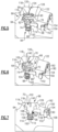
Figure 5 is a perspective view similar toFigure 3 but with a cover. -
Figure 6 is similar toFigure 5 but shows the pinion gear in a locked position. -
Figure 7 is a section view ofFigure 6 . -
Figure 8 is a perspective view showing a retainer that holds the cover on the rotor hub. -
Figure 1 schematically illustrates agas turbine engine 20. Thegas turbine engine 20 is disclosed herein as a two-spool turbofan that generally incorporates afan section 22, acompressor section 24, acombustor section 26 and aturbine section 28. Thefan section 22 may include a single-stage fan 42 having a plurality of fan blades 43. The fan blades 43 may have a fixed stagger angle or may have a variable pitch to direct incoming airflow from an engine inlet. Thefan 42 drives air along a bypass flow path B in abypass duct 13 defined within ahousing 15 such as a fan case or nacelle, and also drives air along a core flow path C for compression and communication into thecombustor section 26 then expansion through theturbine section 28. Asplitter 29 aft of thefan 42 divides the air between the bypass flow path B and the core flow path C. Thehousing 15 may surround thefan 42 to establish an outer diameter of thebypass duct 13. Thesplitter 29 may establish an inner diameter of thebypass duct 13. Although depicted as a two-spool turbofan gas turbine engine in the disclosed nonlimiting embodiment, it should be understood that the concepts described herein are not limited to use with two-spool turbofans as the teachings may be applied to other types of turbine engines including three-spool architectures. Theengine 20 may incorporate a variable area nozzle for varying an exit area of the bypass flow path B and/or a thrust reverser for generating reverse thrust. - The
exemplary engine 20 generally includes alow speed spool 30 and ahigh speed spool 32 mounted for rotation about an engine central longitudinal axis A relative to an enginestatic structure 36 viaseveral bearing systems 38. It should be understood thatvarious bearing systems 38 at various locations may alternatively or additionally be provided, and the location ofbearing systems 38 may be varied as appropriate to the application. - The
low speed spool 30 generally includes aninner shaft 40 that interconnects, a first (or low)pressure compressor 44 and a first (or low)pressure turbine 46. Theinner shaft 40 is connected to thefan 42 through a speed change mechanism, which in the exemplarygas turbine engine 20 is illustrated as a gearedarchitecture 48 to drive thefan 42 at a lower speed than thelow speed spool 30. Theinner shaft 40 may interconnect thelow pressure compressor 44 andlow pressure turbine 46 such that thelow pressure compressor 44 andlow pressure turbine 46 are rotatable at a common speed and in a common direction. In other embodiments, thelow pressure turbine 46 drives both thefan 42 andlow pressure compressor 44 through the gearedarchitecture 48 such that thefan 42 andlow pressure compressor 44 are rotatable at a common speed. Although this application discloses gearedarchitecture 48, its teaching may benefit direct drive engines having no geared architecture. Thehigh speed spool 32 includes anouter shaft 50 that interconnects a second (or high)pressure compressor 52 and a second (or high)pressure turbine 54. Acombustor 56 is arranged in theexemplary gas turbine 20 between thehigh pressure compressor 52 and thehigh pressure turbine 54. Amid-turbine frame 57 of the enginestatic structure 36 may be arranged generally between thehigh pressure turbine 54 and thelow pressure turbine 46. Themid-turbine frame 57 furthersupports bearing systems 38 in theturbine section 28. Theinner shaft 40 and theouter shaft 50 are concentric and rotate via bearingsystems 38 about the engine central longitudinal axis A which is collinear with their longitudinal axes. - Airflow in the core flow path C is compressed by the
low pressure compressor 44 then thehigh pressure compressor 52, mixed and burned with fuel in thecombustor 56, then expanded through thehigh pressure turbine 54 andlow pressure turbine 46. Themid-turbine frame 57 includesairfoils 59 which are in the core flow path C. Theturbines low speed spool 30 andhigh speed spool 32 in response to the expansion. It will be appreciated that each of the positions of thefan section 22,compressor section 24,combustor section 26,turbine section 28, and fandrive gear system 48 may be varied. For example,gear system 48 may be located aft of the low pressure compressor, or aft of thecombustor section 26 or even aft ofturbine section 28, andfan 42 may be positioned forward or aft of the location ofgear system 48. - The
fan 42 may have at least 10 fan blades 43 but no more than 20 or 24 fan blades 43. In examples, thefan 42 may have between 12 and 18 fan blades 43, such as 14 fan blades 43. An exemplary fan size measurement is a maximum radius between the tips of the fan blades 43 and the engine central longitudinal axis A. The maximum radius of the fan blades 43 can be at least 40 inches, or more narrowly no more than 75 inches. For example, the maximum radius of the fan blades 43 can be between 45 inches and 60 inches, such as between 50 inches and 55 inches. Another exemplary fan size measurement is a hub radius, which is defined as distance between a hub of thefan 42 at a location of the leading edges of the fan blades 43 and the engine central longitudinal axis A. The fan blades 43 may establish a fan hub-to-tip ratio, which is defined as a ratio of the hub radius divided by the maximum radius of thefan 42. The fan hub-to-tip ratio can be less than or equal to 0.35, or more narrowly greater than or equal to 0.20, such as between 0.25 and 0.30. The combination of fan blade counts and fan hub-to-tip ratios disclosed herein can provide theengine 20 with a relatively compact fan arrangement. - The
low pressure compressor 44,high pressure compressor 52,high pressure turbine 54 andlow pressure turbine 46 each include one or more stages having a row of rotatable airfoils. Each stage may include a row of vanes adjacent the rotatable airfoils. The rotatable airfoils are schematically indicated at 47, and the vanes are schematically indicated at 49. - The
low pressure compressor 44 andlow pressure turbine 46 can include an equal number of stages. For example, theengine 20 can include a three-stagelow pressure compressor 44, an eight-stagehigh pressure compressor 52, a two-stagehigh pressure turbine 54, and a three-stagelow pressure turbine 46 to provide a total of sixteen stages. In other examples, thelow pressure compressor 44 includes a different (e.g., greater) number of stages than thelow pressure turbine 46. For example, theengine 20 can include a five-stagelow pressure compressor 44, a nine-stagehigh pressure compressor 52, a two-stagehigh pressure turbine 54, and a four-stagelow pressure turbine 46 to provide a total of twenty stages. In other embodiments, theengine 20 includes a four-stagelow pressure compressor 44, a nine-stagehigh pressure compressor 52, a two-stagehigh pressure turbine 54, and a three-stagelow pressure turbine 46 to provide a total of eighteen stages. It should be understood that theengine 20 can incorporate other compressor and turbine stage counts, including any combination of stages disclosed herein. - The
engine 20 may be a high-bypass geared aircraft engine. The bypass ratio can be greater than or equal to 10.0 and less than or equal to about 18.0, or more narrowly can be less than or equal to 16.0. The gearedarchitecture 48 may be an epicyclic gear train, such as a planetary gear system or a star gear system. The epicyclic gear train may include a sun gear, a ring gear, a plurality of intermediate gears meshing with the sun gear and ring gear, and a carrier that supports the intermediate gears. The sun gear may provide an input to the gear train. The ring gear (e.g., star gear system) or carrier (e.g., planetary gear system) may provide an output of the gear train to drive thefan 42. A gear reduction ratio may be greater than or equal to 2.3, or more narrowly greater than or equal to 3.0, and in some embodiments the gear reduction ratio is greater than or equal to 3.4. The gear reduction ratio may be less than or equal to 4.0. The fan diameter is significantly larger than that of thelow pressure compressor 44. Thelow pressure turbine 46 can have a pressure ratio that is greater than or equal to 8.0 and in some embodiments is greater than or equal to 10.0. The low pressure turbine pressure ratio can be less than or equal to 13.0, or more narrowly less than or equal to 12.0.Low pressure turbine 46 pressure ratio is pressure measured prior to an inlet oflow pressure turbine 46 as related to the pressure at the outlet of thelow pressure turbine 46 prior to an exhaust nozzle. It should be understood, however, that the above parameters are only exemplary of one embodiment of a geared architecture engine and that the present invention is applicable to other gas turbine engines including direct drive turbofans. All of these parameters are measured at the cruise condition described below. - A significant amount of thrust is provided by the bypass flow B due to the high bypass ratio. The
fan section 22 of theengine 20 is designed for a particular flight condition -- typically cruise at about 0.8 Mach and about 35,000 feet (10,668 meters). The flight condition of 0.8 Mach and 35,000 ft (10,668 meters), with the engine at its best fuel consumption - also known as "bucket cruise Thrust Specific Fuel Consumption ('TSFC')" - is the industry standard parameter of lbm of fuel being burned divided by lbf of thrust the engine produces at that minimum point. The engine parameters described above, and those in the next paragraph are measured at this condition unless otherwise specified. - "Fan pressure ratio" is the pressure ratio across the fan blade 43 alone, without a Fan Exit Guide Vane ("FEGV") system. A distance is established in a radial direction between the inner and outer diameters of the
bypass duct 13 at an axial position corresponding to a leading edge of thesplitter 29 relative to the engine central longitudinal axis A. The fan pressure ratio is a spanwise average of the pressure ratios measured across the fan blade 43 alone over radial positions corresponding to the distance. The fan pressure ratio can be less than or equal to 1.45, or more narrowly greater than or equal to 1.25, such as between 1.30 and 1.40. "Corrected fan tip speed" is the actual fan tip speed in ft/sec divided by an industry standard temperature correction of [(Tram °R) / (518.7 °R)]0.5. The corrected fan tip speed can be less than or equal to 1150.0 ft / second (350.5 meters/second), and can be greater than or equal to 1000.0 ft / second (304.8 meters/second). - The
fan 42,low pressure compressor 44 andhigh pressure compressor 52 can provide different amounts of compression of the incoming airflow that is delivered downstream to theturbine section 28 and cooperate to establish an overall pressure ratio (OPR). The OPR is a product of the fan pressure ratio across a root (i.e., 0% span) of the fan blade 43 alone, a pressure ratio across thelow pressure compressor 44 and a pressure ratio across thehigh pressure compressor 52. The pressure ratio of thelow pressure compressor 44 is measured as the pressure at the exit of thelow pressure compressor 44 divided by the pressure at the inlet of thelow pressure compressor 44. In examples, a sum of the pressure ratio of thelow pressure compressor 44 and the fan pressure ratio is between 3.0 and 6.0, or more narrowly is between 4.0 and 5.5. The pressure ratio of the highpressure compressor ratio 52 is measured as the pressure at the exit of thehigh pressure compressor 52 divided by the pressure at the inlet of thehigh pressure compressor 52. In examples, the pressure ratio of thehigh pressure compressor 52 is between 9.0 and 12.0, or more narrowly is between 10.0 and 11.5. The OPR can be equal to or greater than 45.0, and can be less than or equal to 70.0, such as between 50.0 and 60.0. The overall and compressor pressure ratios disclosed herein are measured at the cruise condition described above, and can be utilized in two-spool architectures such as theengine 20 as well as three-spool engine architectures. - The
engine 20 establishes a turbine entry temperature (TET). The TET is defined as a maximum temperature of combustion products communicated to an inlet of theturbine section 28 at a maximum takeoff (MTO) condition. The inlet is established at the leading edges of the axially forwardmost row of airfoils of theturbine section 28, and MTO is measured at maximum thrust of theengine 20 at static sea-level and 86 degrees Fahrenheit, °F (30 °C). The TET may be greater than or equal to 2,700.0 °F (1,480 °C), or more narrowly less than or equal to 3,500.0 °F (1,925 °C), such as between 2,750.0 °F (1,510 °C) and 3,350.0 °F (1,845 °C). The relatively high TET can be utilized in combination with the other techniques disclosed herein to provide a compact turbine arrangement. - The
engine 20 establishes an exhaust gas temperature (EGT). The EGT is defined as a maximum temperature of combustion products in the core flow path C communicated to at the trailing edges of the axially aftmost row of airfoils of theturbine section 28 at the MTO condition. The EGT may be less than or equal to 1,000.0 °F (540 °C), or more narrowly greater than or equal to 800.0 °F (425 °C), such as between 900.0 °F (480 °C) and 975.0 °F (525 °C). The relatively low EGT can be utilized in combination with the other techniques disclosed herein to reduce fuel consumption. - The
example engine 20 described above with regard toFigure 1 may include a balancing system to minimize vibrations.Figure 2 shows an example of arotor disk 60 including one or more rows ofblades 62 supported on arotor hub 64, as part of arotor assembly 52, for rotation about the center axis A. In one example, therotor 60 comprises a HPC rotor supported on arotor hub 64, that is coupled to thehigh rotor shaft 50. A balancingsystem 66 is used to balance therotor 60 to minimize vibrations. In one example, the balancingsystem 66 is mounted to therear HPC hub 64 at a location that is aft of theblades 62, and which has an increased thickness portion for greater support. Thebalancing system 66 could also be used at other rotor locations. - In one example, the balancing
system 66 comprises a balancingring 68 and apinion gear 70 as shown inFigure 3 . The balancingring 68 is configured to surround thehub 64 and includes a plurality ofring teeth 72. Thepinion gear 70 includes a plurality ofgear teeth 74 that are in meshing engagement with the plurality ofring teeth 72. In one example, thepinion gear 70 is selectively rotated to adjust a position of the balancingring 68 relative to thehub 64 via the meshing engagement. - In one example, shown in
Figure 4 , the balancingring 68 has afirst portion 76 defining a first weight characteristic and asecond portion 78 defining a second weight characteristic that is greater than the first weight characteristic. In one example, the balancingring 68 has an innerperipheral surface 80, and the balancingring 68 further comprises a section of the balancingring 68 where a portion of the innerperipheral surface 80 is spaced from an outerperipheral surface 82 of thehub 64 by a gap 84 (Figure 3 ). In the same example, thesecond portion 78 comprises a section of the balancingring 68 where there is nogap 84.Gap 84 atlocation 76 transitions to no gap atlocation 78. The gap can transition linearly or by another shape. The balancingring 68 is always piloted at arear area 77, while the balancingring 68 is not piloted where there is thegap 84. Thesecond portion 78 is fully piloted as there is nogap 84. - This is best shown in
Figure 4 where an upper portion of the balancingring 68 comprises thefirst portion 76 that is spaced from thehub 64 by thegap 84, and the lower portion of the balancingring 68 comprises thesecond portion 78 that does not include thegap 84 between thering 68 and thehub 64. In one example, the upper portion, comprising thefirst portion 76, extends circumferentially around the center axis A for a first arc length 86, and the lower portion, comprising thesecond portion 78, extends circumferentially around the center axis A for asecond arc length 88. This provides for a different weight distribution of the balancingring 68 about the axis A as there is more material in the a cross-section of thering 68 in thesecond portion 78 than in a cross-section in thefirst portion 76. Thus, thefirst portion 76 for the first arc length 86 comprises a minimum weight location while thesecond portion 78 for thesecond arc length 88 comprises a maximum weight location. In one example, thesecond arc length 88 is less than the first arc length 86. The transition can be linear or some other shape such that the arc sectors are not necessarily 120 degrees. - In one example, the balancing
ring 68 is positioned eccentric to thehub 64. In other words, a center of the balancingring 68 is offset or radially spaced from the center axis A about which thehub 64 rotates. In one example, the balancingring 68 has eccentric heavier weighted material on thesecond portion 78 as described above. - In one example, the
pinion gear 70 is selectively moveable between a locked position (Figures 6 and 7 ) where the balancingring 68 is prevented from rotating, and an unlocked position (Figures 3 and5 ) where the balancingring 68 can rotate relative to thehub 64. In one example, thehub 64 includes a first set of lock features 90 and thepinion gear 70 includes a second set of lock features 92 that engage with the first set of lock features 90 when thepinion gear 70 is in the locked position. - In one example, the
pinion gear 70 is resiliently biased to the locked position.Figures 5-7 show an example of a biasingassembly 94 that is coupled to a radially inner end of thepinion gear 70. In one example, the biasingassembly 94 comprising a fitting 96, aresilient member 98, and athrust washer 100. - In one example, the
pinion gear 70 comprises ahead portion 102, a toothed portion with the plurality ofgear teeth 74, and ashaft portion 104 that extends from the toothed portion to a distal end 106 (Figure 7 ). Thedistal end 106 of theshaft portion 104 comprises a reduced cross-section compared to the cross-section at the toothed portion and thus forms ashoulder 108 between the two sections. This reduced sectiondistal end 106 is received within aninternal cavity 110 of the fitting 96. The fitting 96 includes aflange 112 that is seated on theshoulder 108. Thehub 64 includes abore 114 with an end face that seats thethrust washer 100. In one example, theresilient member 98 comprises a coil spring that has one end seated against theflange 112 and an opposite end reacting against thethrust washer 100. Theresilient member 98 biases thepinion gear 70 to the locked position. - In one example, the
head portion 102 of thepinion gear 70 has an outer peripheral dimension that is greater than an outer peripheral dimension of thegear teeth 74. In one example, the second set of lock features 92 is formed about an outer periphery of thehead potion 102. In one example, the second set of lock features 92 comprise a first set of castellations. - In one example, the
hub 64 includes ashelf 116 having anouter surface 118 that extends to ashelf edge 120. In one example configuration, the balancingsystem 66 includes acover 122 that extends to acover edge 124 that is generally flush with theshelf edge 120. Additionally, anouter surface 126 of thecover 122 is generally flush with theouter surface 118 of theshelf 116. Thecover 122 cooperates with theshelf 118 to enclose thebalancing system 66 cavity and cover thebalancing ring 68. The respective flush surfaces 118, 126 of theshelf 116 and cover 122 provide a non-interrupted surface at their associated mating region which significantly reduces local air and component heat up due to air windage. - In one example, the
shelf edge 120 and thecover edge 124 cooperate with each other to provide the first set of lock features 90, which surround thehead portion 102 of thepinion gear 70. In one example, the first set of lock features 90 comprise a second set of castellations that mate with the first set of castellations as shown inFigure 6 when thepinion gear 70 is in the locked position. As shown inFigure 7 , thepinion gear 70 does not extend radially outward of theouter surfaces shelf 116 or cover 122 when in the locked position. This also reduces the air windage effect. - The pinion to ring gear teeth cannot be a miter type gear set because the pinion gear teeth need to be able to slide from a disengaged/locked position to an engaged position, and then back again. In one example, the
pinion gear 70 is pushed radially, or substantially radially, inwardly in response to a tool input force against a biasing force of theresilient member 98 such that the first set of lock features 90 disengages from the second set of lock features 92 (Figure 5 ) to allow thepinion gear 70 to rotate the balancingring 68 to a desired adjustment position. This adjustment can occur during engine assembly, as well as on-wing during maintenance operations. In one example, in-line locking bore scope plug access, associated with thepinion gear 70 as indicated at 130 (Figure 2 ), is accessible through anaccess port 132 formed in anengine casing 134 that surrounds therotor 60. This allows a tool to interface with theadjustment pinion 70. In one example, theaccess port 132 is a bolted plug type access port as shown inFigure 2 . - In one example, the
pinion gear 70 is at substantially 90 degrees relative to thering 68; however, this can vary between +/- 45 degrees, provided thering gear teeth 72 are substantially 90 degrees to thepinion gear teeth 74. In one example, the pinion gear rotates about an axis that is non-concentric with thering 68. Additionally, the ring teeth and the pinion teeth could be at an angle, as long as they are straight teeth. - In one example method, the eccentric geared balancing
ring 68 is indexed by the spring-loaded gearedpinion 70 through small increments of adjustment. In one example, if engine vibration is encountered in the field, a high spool rotation is performed to determine a balance correction sector mass and angular location. Those skilled in the art who have the benefit of this description will be able to determine the balance correction sector mass and angular location based on the engine performance. Once this is determined, thepinion gear 70 is then pushed inward, by a screw driver type tool or other similar tool (not shown), to overcome the biasing force of theresilient member 98 and move thepinion gear 70 to the unlocked position. In one example, an end face of thehead portion 102 of thepinion gear 70 includes slots orrecesses 140 to engage with the tool. Thepinion gear 70 is then incrementally rotated by a tool that fits throughseveral access ports gear balancing ring 68 is in the desired adjustment position. In one example, timing marks 136 are provided on thepinion gear 70 and thehub 64, as well as on the tool, to determine number of turns needed to achieve the desired adjustment position. The tool is then withdrawn, and thepinion gear 70 pops outward via the biasing force to engage the first and second sets castellations and lock both thepinion gear 70 and thegear balancing ring 68 from rotation. Centrifugal loading also provides this function. In this position, the use of the continuousforward hub shelf 116 and thecover 122 provides a shield to prevent windage heat up. - In one example, the balancing
system 66 is moved to a location on therear HPC hub 64 to further ease the access procedure. The increase in radial height location also increases a centrifugal load of the heavy material and allows for smaller adjustments. - In one example, a
capture plate 150 and retainer assembly are used to hold thecover 122 on thehub 64. In one example, the retainer assembly is comprised of alocking split ring 152 and a splitlock wire ring 154. The following is an example method of assembling thecover 122 to thehub 64. First, thecover 122 is slid onto thehub 64 and is seated against a shoulder 156. Next, thesplit ring 152 is pulled apart against its biasing force and installed within agroove 158 adjacent to the shoulder 156. Thesplit ring 152 is then released with the biasing force resiliently retaining thesplit ring 152 against thecover 122 andhub 64. Next, thecapture plate 150 is installed to fit between an outer surface of thesplit ring 152 and an inner surface of thecover 122. In one example, thecapture plate 150 includes arecess 160 that receives a shoulder orlip 162 of thecover 122. In one example, as shown inFigure 8 , an outer peripheral surface of thecapture plate 150 includes protrusions or tabs 164 that fit into corresponding recesses orcutout castellations 166 formed within an inner surface of thecover 122. The positions of the recesses and protrusions could also be reversed. Finally, the splitlock wire ring 154, is installed by compressing it to a smaller diameter against its biasing force toclear shelf lip 180 oncover 122, or in another embodiment spirally fed in through aloading slot 182 incover 122 against thecapture plate 150 to resiliently hold theplate 150 against thecover 122. - Although embodiment have been disclosed, a worker of skill in this art would recognize that modification would come within the scope of the invention. For that reason, the following claims should be studied to determine the true scope and content of the invention.
Claims (15)
- A balancing system (66) comprising:a rotor hub (64) having a center axis (A);a balancing ring (68) surrounding the rotor hub (64), the balancing ring (68) including a plurality of ring teeth (72); anda pinion gear (70) including a plurality of gear teeth (74) in meshing engagement with the plurality of ring teeth (72), wherein the pinion gear (70) is selectively rotated to adjust a position of the balancing ring (68) relative to the rotor hub (64).
- The balancing system (66) of claim 1, wherein the balancing ring (68) has a first portion (76) defining a first weight characteristic and a second portion (78) defining a second weight characteristic that is greater than the first weight characteristic, and wherein, optionally, the balancing ring (68) is configured such that a center of the balancing ring (68) is offset from the center axis.
- The balancing system (66) of claim 2, wherein:the balancing ring (68) has an inner peripheral surface (80), the first portion (76) comprises a section of the balancing ring (68) where a portion of the inner peripheral surface (80) is spaced from an outer peripheral surface (82) of the rotor hub (64) by a gap (84), and the second portion (78) comprises a section of the balancing ring (68) that does not include the gap (84); and/orthe first portion (76) extends circumferentially around the center axis for a first arc length (86) and the second portion (78) extends circumferentially around the center axis for a second arc length (88) that is less than the first arc length (86).
- The balancing system (66) of any preceding claim, wherein the pinion gear (70) is selectively moveable between a locked position where the balancing ring (68) is prevented from rotating and an unlocked position where the balancing ring (68) is allowed to rotate relative to the rotor hub (64), and wherein, optionally, the pinion gear (70) is resiliently biased to the locked position.
- The balancing system (66) of claim 4, wherein the rotor hub (64) includes a first set of lock features (90), and the pinion gear (70) includes a second set of lock features (92) that engage with the first set of lock features (90) when the pinion gear (70) is in the locked position.
- The balancing system (66) of any preceding claim, wherein the rotor hub (64) comprises a compressor rotor hub (64) and includes a shelf (116) having an outer surface (118) that extends to a shelf edge (120), and including a cover (122) that extends to a cover edge (124) that is generally flush with the shelf edge (120), and wherein the pinion gear (70) does not extend radially outward of the shelf (116) or cover (122).
- A gas turbine engine (20) comprising:the balancing system of any of claims 1 to 4;a compressor section (24);a combustor (56); anda turbine section (28), wherein the compressor section (24) has at least one compressor rotor (60) comprising the rotor hub (64), the rotor hub (64) supporting at least one row of blades (62) for rotation about the center axis (A).
- The gas turbine engine (20) of claim 7, wherein the rotor hub (64) includes a shelf (116) having an outer surface (118) that extends to a shelf edge (120), and including a cover (122) that extends to a cover edge (124) that is generally flush with the shelf edge (120), the pinion gear (70) includes a first set of lock features (92), the shelf (116) and cover (122) provide a second set of lock features (90) that receive the first set of lock features (92) with the pinion gear (70) is in a or the locked position, and the pinion gear (70) does not extend radially outward of the shelf (116) or cover (122) when in the locked position.
- The gas turbine engine (20) of claim 8, wherein said pinion gear (70) is configured to be pushed radially inwardly in response to a tool input force against a biasing force such that the first set of lock features (92) disengages from the second set of lock features (90) to allow the pinion gear (70) to rotate the balancing ring (68).
- The gas turbine engine (20) of claim 8 or 9, comprising a capture plate (150) and retainer to hold the cover (122) on the rotor hub (64), wherein one of the cover (122) and the capture plate (150) includes protrusions and the other of the cover (122) and the capture plate (150) includes recesses (140) to receive the protrusions.
- The gas turbine engine (20) of any of claims 7 to 10, comprising an engine casing (134) extending around the at least one compressor rotor (60), wherein the pinion gear (70) is accessible through an access port (132) formed within the engine casing (134).
- A method comprising:installing a balancing ring (68) to surround a rotor hub (64) that rotates about a center axis (A);engaging gear teeth (74) of a pinion gear (70) with ring teeth (72) on the balancing ring (68); andselectively rotating the pinion gear (70) to adjust a position of the balancing ring (68) relative to the rotor hub (64).
- The method of claim 12, comprising moving the pinion gear (70) from a locked position where the pinion gear (70) is prevented from rotating to an unlocked position to allow the pinion gear (70) to rotate the balancing ring (68).
- The method of claim 12 or 13, comprising:accessing the pinion gear (70) through an access port (132) provided on an engine casing (134) that surrounds the rotor hub (64); and/oroffsetting a center of the balancing ring (68) from the center axis.
- The method of claim 12, 13 or 14, comprising rotating the pinion gear (70) about an axis that is non-concentric with the center axis, installing a cover (122) on the rotor hub (64), and installing a retainer to hold the cover (122) on the rotor hub (64) such that an edge of the cover (122) is flush with an edge on the rotor hub (64) and such that the pinion gear (70) does not extend radially outward of the rotor hub (64) or cover (122).
Applications Claiming Priority (1)
| Application Number | Priority Date | Filing Date | Title |
|---|---|---|---|
| US18/229,967 US12215715B1 (en) | 2023-08-03 | 2023-08-03 | Engine trim balance system |
Publications (2)
| Publication Number | Publication Date |
|---|---|
| EP4517045A2 true EP4517045A2 (en) | 2025-03-05 |
| EP4517045A3 EP4517045A3 (en) | 2025-03-19 |
Family
ID=92212664
Family Applications (1)
| Application Number | Title | Priority Date | Filing Date |
|---|---|---|---|
| EP24192693.0A Pending EP4517045A3 (en) | 2023-08-03 | 2024-08-02 | System for balancing a rotor of a gas turbine engine, gas turbine engine and method of balancing a rotor of a gas turbine engine |
Country Status (2)
| Country | Link |
|---|---|
| US (1) | US12215715B1 (en) |
| EP (1) | EP4517045A3 (en) |
Family Cites Families (11)
| Publication number | Priority date | Publication date | Assignee | Title |
|---|---|---|---|---|
| US1730019A (en) * | 1925-08-25 | 1929-10-01 | Westinghouse Electric & Mfg Co | Balancing machine |
| US5167167A (en) * | 1991-11-18 | 1992-12-01 | United Technologies Corporation | Rotor trim balancing |
| US7234916B2 (en) | 2004-09-16 | 2007-06-26 | General Electric Company | Method and apparatus for balancing gas turbine engines |
| US7296976B2 (en) | 2004-10-20 | 2007-11-20 | Rolls-Royce Corporation | Dual counterweight balancing system |
| US7371042B2 (en) | 2004-12-21 | 2008-05-13 | General Electric Company | Method and apparatus for balancing gas turbine engines |
| US7465146B2 (en) | 2005-12-05 | 2008-12-16 | General Electric Company | Methods and systems for turbine rotor balancing |
| US8668457B2 (en) | 2010-10-29 | 2014-03-11 | United Technologies Corporation | Gas turbine engine trim balance |
| DE102011102315A1 (en) * | 2011-05-23 | 2012-11-29 | Rolls-Royce Deutschland Ltd & Co Kg | Gas turbine balancing device for use in turbo-engine of aircraft, has balancing rings rotatable by tool that is operated in mounted condition of gas turbine and fixed relative to each other and relative to groove by fixing device |
| US9279324B2 (en) | 2011-12-07 | 2016-03-08 | Dresser-Rand Company | Reduced leakage balance piston seal |
| US9404367B2 (en) | 2012-11-21 | 2016-08-02 | Solar Turbines Incorporated | Gas turbine engine compressor rotor assembly and balancing system |
| US10697300B2 (en) | 2017-12-14 | 2020-06-30 | Raytheon Technologies Corporation | Rotor balance weight system |
-
2023
- 2023-08-03 US US18/229,967 patent/US12215715B1/en active Active
-
2024
- 2024-08-02 EP EP24192693.0A patent/EP4517045A3/en active Pending
Also Published As
| Publication number | Publication date |
|---|---|
| US12215715B1 (en) | 2025-02-04 |
| US20250043802A1 (en) | 2025-02-06 |
| EP4517045A3 (en) | 2025-03-19 |
Similar Documents
| Publication | Publication Date | Title |
|---|---|---|
| EP3187722B1 (en) | Nacelle short inlet for fan blade removal | |
| US20140186158A1 (en) | Gas turbine engine shaft bearing configuration | |
| EP3708772B1 (en) | Tie shaft assembly for a gas turbine engine | |
| EP2880282B1 (en) | Compressor assembly with stator anti-rotation lug | |
| EP3418492B1 (en) | Bolt retention assembly for gas turbine engine | |
| EP2964522B1 (en) | Gas turbine engine nose cone attachment | |
| US10927768B2 (en) | Spline ring for a fan drive gear flexible support | |
| EP2943658B1 (en) | Stator anti-rotation device | |
| EP4517050A1 (en) | Cmc vane with rotatable baffle design to accommodate re-stagger | |
| EP3667048B1 (en) | Planet carrier and method of assembling of a planet carrier | |
| EP3564495B1 (en) | Gas turbine engine exhaust component | |
| US12215715B1 (en) | Engine trim balance system | |
| US11286797B2 (en) | Gas turbine engine stator vane base shape | |
| US12228142B1 (en) | Control of leakage for gas turbine engine compressor blades | |
| US20140161616A1 (en) | Multi-piece blade for gas turbine engine | |
| US12480418B1 (en) | Seal assembly for gas turbine engines | |
| EP4311917B1 (en) | Bleed hole flow discourager | |
| EP4495402B1 (en) | Bifurcation air scoop for gas turbine engine | |
| EP4123142A1 (en) | Gas turbine engine with higher low spool torque-to-thrust ratio | |
| EP4596842A1 (en) | Turbine section for a gas turbine engine, gas turbine engine and method of attaching a blade outer air seal to a static structure of a gas turbine engine | |
| EP4517049A1 (en) | Bathtub seal integrated into cmc vane load path | |
| EP3495621B1 (en) | Support ring for a gas turbine engine | |
| US20230026997A1 (en) | Gas turbine engine compressor arrangement | |
| EP3045658B1 (en) | Gas turbine engine rotor |
Legal Events
| Date | Code | Title | Description |
|---|---|---|---|
| PUAI | Public reference made under article 153(3) epc to a published international application that has entered the european phase |
Free format text: ORIGINAL CODE: 0009012 |
|
| STAA | Information on the status of an ep patent application or granted ep patent |
Free format text: STATUS: THE APPLICATION HAS BEEN PUBLISHED |
|
| PUAL | Search report despatched |
Free format text: ORIGINAL CODE: 0009013 |
|
| AK | Designated contracting states |
Kind code of ref document: A2 Designated state(s): AL AT BE BG CH CY CZ DE DK EE ES FI FR GB GR HR HU IE IS IT LI LT LU LV MC ME MK MT NL NO PL PT RO RS SE SI SK SM TR |
|
| AK | Designated contracting states |
Kind code of ref document: A3 Designated state(s): AL AT BE BG CH CY CZ DE DK EE ES FI FR GB GR HR HU IE IS IT LI LT LU LV MC ME MK MT NL NO PL PT RO RS SE SI SK SM TR |
|
| RIC1 | Information provided on ipc code assigned before grant |
Ipc: F16F 15/32 20060101ALN20250207BHEP Ipc: G01M 1/36 20060101ALN20250207BHEP Ipc: F01D 5/02 20060101AFI20250207BHEP |
|
| STAA | Information on the status of an ep patent application or granted ep patent |
Free format text: STATUS: REQUEST FOR EXAMINATION WAS MADE |
|
| 17P | Request for examination filed |
Effective date: 20250919 |