EP4516976A1 - Method for manufacturing carbon nanotube twisted yarn - Google Patents
Method for manufacturing carbon nanotube twisted yarn Download PDFInfo
- Publication number
- EP4516976A1 EP4516976A1 EP23795995.2A EP23795995A EP4516976A1 EP 4516976 A1 EP4516976 A1 EP 4516976A1 EP 23795995 A EP23795995 A EP 23795995A EP 4516976 A1 EP4516976 A1 EP 4516976A1
- Authority
- EP
- European Patent Office
- Prior art keywords
- carbon nanotube
- twisted
- yarn
- sheet
- range
- Prior art date
- Legal status (The legal status is an assumption and is not a legal conclusion. Google has not performed a legal analysis and makes no representation as to the accuracy of the status listed.)
- Pending
Links
Images


Classifications
-
- D—TEXTILES; PAPER
- D02—YARNS; MECHANICAL FINISHING OF YARNS OR ROPES; WARPING OR BEAMING
- D02G—CRIMPING OR CURLING FIBRES, FILAMENTS, THREADS, OR YARNS; YARNS OR THREADS
- D02G3/00—Yarns or threads, e.g. fancy yarns; Processes or apparatus for the production thereof, not otherwise provided for
- D02G3/02—Yarns or threads characterised by the material or by the materials from which they are made
- D02G3/16—Yarns or threads made from mineral substances
-
- C—CHEMISTRY; METALLURGY
- C01—INORGANIC CHEMISTRY
- C01B—NON-METALLIC ELEMENTS; COMPOUNDS THEREOF; METALLOIDS OR COMPOUNDS THEREOF NOT COVERED BY SUBCLASS C01C
- C01B32/00—Carbon; Compounds thereof
- C01B32/15—Nano-sized carbon materials
- C01B32/158—Carbon nanotubes
- C01B32/168—After-treatment
-
- D—TEXTILES; PAPER
- D01—NATURAL OR MAN-MADE THREADS OR FIBRES; SPINNING
- D01F—CHEMICAL FEATURES IN THE MANUFACTURE OF ARTIFICIAL FILAMENTS, THREADS, FIBRES, BRISTLES OR RIBBONS; APPARATUS SPECIALLY ADAPTED FOR THE MANUFACTURE OF CARBON FILAMENTS
- D01F9/00—Artificial filaments or the like of other substances; Manufacture thereof; Apparatus specially adapted for the manufacture of carbon filaments
- D01F9/08—Artificial filaments or the like of other substances; Manufacture thereof; Apparatus specially adapted for the manufacture of carbon filaments of inorganic material
- D01F9/12—Carbon filaments; Apparatus specially adapted for the manufacture thereof
- D01F9/127—Carbon filaments; Apparatus specially adapted for the manufacture thereof by thermal decomposition of hydrocarbon gases or vapours or other carbon-containing compounds in the form of gas or vapour, e.g. carbon monoxide, alcohols
-
- D—TEXTILES; PAPER
- D02—YARNS; MECHANICAL FINISHING OF YARNS OR ROPES; WARPING OR BEAMING
- D02G—CRIMPING OR CURLING FIBRES, FILAMENTS, THREADS, OR YARNS; YARNS OR THREADS
- D02G3/00—Yarns or threads, e.g. fancy yarns; Processes or apparatus for the production thereof, not otherwise provided for
- D02G3/22—Yarns or threads characterised by constructional features, e.g. blending, filament/fibre
- D02G3/26—Yarns or threads characterised by constructional features, e.g. blending, filament/fibre with characteristics dependent on the amount or direction of twist
-
- D—TEXTILES; PAPER
- D10—INDEXING SCHEME ASSOCIATED WITH SUBLASSES OF SECTION D, RELATING TO TEXTILES
- D10B—INDEXING SCHEME ASSOCIATED WITH SUBLASSES OF SECTION D, RELATING TO TEXTILES
- D10B2101/00—Inorganic fibres
- D10B2101/10—Inorganic fibres based on non-oxides other than metals
- D10B2101/12—Carbon; Pitch
- D10B2101/122—Nanocarbons
-
- D—TEXTILES; PAPER
- D10—INDEXING SCHEME ASSOCIATED WITH SUBLASSES OF SECTION D, RELATING TO TEXTILES
- D10B—INDEXING SCHEME ASSOCIATED WITH SUBLASSES OF SECTION D, RELATING TO TEXTILES
- D10B2401/00—Physical properties
- D10B2401/06—Load-responsive characteristics
- D10B2401/063—Load-responsive characteristics high strength
-
- D—TEXTILES; PAPER
- D10—INDEXING SCHEME ASSOCIATED WITH SUBLASSES OF SECTION D, RELATING TO TEXTILES
- D10B—INDEXING SCHEME ASSOCIATED WITH SUBLASSES OF SECTION D, RELATING TO TEXTILES
- D10B2401/00—Physical properties
- D10B2401/16—Physical properties antistatic; conductive
Definitions
- the present invention relates to a method for manufacturing a twisted carbon nanotube yarn.
- Carbon nanotubes have excellent mechanical properties, electrical properties, thermal properties, or the like, and are expected to be used in industries, such as field emission displays or conductive fillers.
- a twisted carbon nanotube yarn made by spinning carbon nanotube fibers is expected to be used.
- a twisted carbon nanotube yarn is produced by twisting a sheet of carbon nanotubes drawn in yarn form from a carbon nanotube substrate.
- the strength of the carbon nanotube sheet drawn from the carbon nanotube substrate is low. This resulted in a problem that when the carbon nanotubes drawn from the substrate were strongly twisted, the fibers broke.
- the twisted carbon nanotube yarn produced as described above was very thin. This resulted in a problem that the yarn had insufficient tensile strength and electrical conductivity.
- Patent Literature 1 describes a method for manufacturing a twisted carbon nanotube yarn, in which a twisted yarn containing carbon nanotubes is irradiated with an electron beam.
- Patent Literature 1 Japanese Unexamined Patent Application Publication No. 2011-153392
- a method for manufacturing a twisted carbon nanotube yarn includes a step of drawing carbon nanotubes in sheet form from an end portion of a carbon nanotube forest to provide a carbon nanotube sheet (drawing step), a step of performing a false twisting step of twisting the carbon nanotube sheet and then performing untwisting to provide a carbon nanotube linear body (false twisting step), and a step of twisting the carbon nanotube linear body to provide a twisted carbon nanotube yarn (main twisting step).
- the false twisting step of twisting the carbon nanotube sheet and then performing untwisting is performed.
- This can increase the strength of the carbon nanotube linear body before the main twisting step.
- the fibers can be prevented from breaking.
- a twisted carbon nanotube yarn sufficiently twisted can be produced, and a twisted carbon nanotube yarn having excellent strength and electrical conductive properties can be manufactured.
- a carbon nanotube forest is prepared.
- any known substrate can be used as appropriate.
- a plastic substrate, a glass substrate, a silicon substrate, or a metal substrate containing a metal such as iron or copper or an alloy thereof can be used.
- a silicon dioxide film may be stacked on a surface of any of these substrates.
- the carbon nanotubes grown by chemical vapor deposition on the substrate may be single-walled carbon nanotubes, double-walled carbon nanotubes, multi-walled carbon nanotubes, or a mixture thereof.
- the form of the carbon nanotube assembly is not particularly limited. From the viewpoint of facilitating the formation of twisted carbon nanotube yarn, a high-density, highly oriented assembly formed on a substrate is preferred.
- the carbon nanotubes on the substrate preferably have a bulk density of 20 mg/cm 3 or more. When the bulk density is 20 mg/cm 3 or more, the drawability can be improved.
- the term "highly oriented" indicates that the carbon nanotubes are adjacent to each other and oriented perpendicular to a planar surface of the substrate.
- the height (length) of the carbon nanotubes in the carbon nanotube assembly is preferably, on average, 100 ⁇ m or more, and more preferably 150 ⁇ m or more.
- the number of layers of the carbon nanotubes in the carbon nanotube assembly may be one or more, and is preferably in a range from 1 to 40.
- carbon nanotubes are drawn in sheet form from an end portion of the carbon nanotube forest to provide a carbon nanotube sheet.
- the carbon nanotube sheet can be drawn with a known drawing tool.
- the width of the carbon nanotube sheet is preferably in a range from 20 mm to 200 mm, more preferably in a range from 25 mm to 100 mm.
- the false twisting step the false twisting step of twisting the carbon nanotube sheet obtained in the drawing step and then performing untwisting is performed, thereby providing a carbon nanotube linear body.
- the carbon nanotube sheet can be twisted by rotating a roller or the like holding the carbon nanotube sheet.
- the carbon nanotube sheet may be twisted by winding it on a roller or the like.
- a known method can be employed.
- a roller or the like holding the twisted carbon nanotube sheet can be rotated in the opposite direction to that in which the twisting was performed, thereby untwisting the carbon nanotube sheet.
- the twisted carbon nanotube sheet may be untwisted by pulling the sheet back from the roller or the like on which the sheet is wound. That is, in the case of performing twisting with a roller or the like, when the roller twists the sheet clockwise, the sheet on the outlet side naturally has a counterclockwise twist and returns to zero twist (no twist). It is preferable to ensure a path line long enough to allow the twist to return naturally.
- the number of twists when the carbon nanotube sheet is false-twisted in the false twisting step needs to be in a range from 300 T/m to 5,000 T/m, preferably in a range from 500 T/m to 5,000 T/m, and more preferably in a range from 700 T/m to 5,000 T/m.
- the number of twists when the false-twisted carbon nanotube sheet is untwisted is preferably in a range from 300 T/m to 5,000 T/m, more preferably in a range from 500 T/m to 5,000 T/m, and still more preferably in a range from 700 T/m to 5,000 T/m.
- the strength of the carbon nanotube linear body can be increased.
- the carbon nanotube linear body obtained in the false twisting step is twisted to provide a twisted carbon nanotube yarn.
- the carbon nanotube linear body can be twisted by rotating a roller or the like holding the carbon nanotube linear body.
- the twisted carbon nanotube yarn is wound on a bobbin. At this time, although the twisted carbon nanotube yarn is pulled, the carbon nanotube linear body can be prevented from breaking, this is because the strength of the carbon nanotube linear body has been improved in the false twisting step.
- the number of twists when the carbon nanotube linear body is twisted needs to be in a range from 900 T/m to 5,000 T/m, more preferably in a range from 1,000 T/m to 3,000 T/m, and still more preferably 1,000 T/m to 2,000 T/m.
- the twisted carbon nanotube yarn according to the exemplary embodiment is obtained.
- the resulting twisted carbon nanotube yarn preferably satisfies the following requirements.
- the diameter of the twisted carbon nanotube yarn is preferably in a range from 1 ⁇ m to 1,000 ⁇ m, more preferably in a range from 15 ⁇ m to 100 ⁇ m, and still more preferably in a range from 25 ⁇ m to 75 ⁇ m.
- the twist angle of the twisted carbon nanotube yarn is preferably in a range from 8 degrees to 50 degrees, more preferably in a range from 10 degrees to 30 degrees.
- the twist angle can be adjusted by the number of twists when the carbon nanotube linear body is twisted.
- the twist may be untwisted after the main twisting step so that the twist angle falls within the above range.
- the void fraction of the twisted carbon nanotube yarn is preferably in a range from 0% to 1%, more preferably in a range from 0% to 0.5%. When the void fraction is within the above range, the strength and electrical conductive properties of the twisted carbon nanotube yarn can be improved.
- the void fraction of the twisted carbon nanotube yarn can be measured by image analysis of a scanning electron microscope (SEM) photograph.
- the void fraction can be calculated by observing a cross section of the twisted carbon nanotube yarn with a SEM and binarizing a carbon nanotube portion and a void portion.
- Void fraction [%] (area of void portion/cross-sectional area of twisted carbon nanotube yarn) ⁇ 100
- the electrical conductivity of the twisted carbon nanotube yarn is preferably in a range from 6.0 ⁇ 10 2 S/cm to 6.3 ⁇ 10 5 S/cm.
- the electrical conductivity of the twisted carbon nanotube yarn can be calculated by measuring the diameter ( ⁇ m) and line resistance ( ⁇ /cm) of the twisted carbon nanotube yarn and converting them into electrical conductivity per cross-sectional area.
- the tensile strength of the twisted carbon nanotube yarn can be measured by a method described in JIS L1095.
- a carbon nanotube forest was cut so as to have a width of 33 mm. From an end portion thereof, the carbon nanotubes were drawn in sheet form (width: 33 mm) in a direction in which the deviation from the parallel direction of the carbon nanotube forest was within 10 degrees, thereby providing a carbon nanotube sheet.
- the resulting carbon nanotube sheet was bundled in yarn form using a guide, and a false twisting step was performed by twisting the yarn-like carbon nanotube (the number of twists: 1,000 T/m) and untwisting it (allowing it to return naturally), thereby providing a carbon nanotube linear body.
- the resulting carbon nanotube linear body was twisted (the number of twists: 1,200 T/m) and wound on a bobbin to provide a twisted carbon nanotube yarn.
- a carbon nanotube forest was cut so as to have a width of 33 mm. From an end portion thereof, the carbon nanotubes were drawn in sheet form (width: 33 mm) in a direction in which the deviation from the parallel direction of the carbon nanotube forest was within 10 degrees, thereby providing a carbon nanotube sheet. The resulting carbon nanotube sheet was bundled in yarn form using a guide. The yarn-like carbon nanotube was twisted (the number of twists: 1,000 T/m) and then untwisted (naturally returned), thereby providing a carbon nanotube yarn.
- a carbon nanotube forest was cut so as to have a width of 33 mm. From an end portion thereof, the carbon nanotubes were drawn in sheet form (width: 33 mm) in a direction in which the deviation from the parallel direction of the carbon nanotube forest was within 10 degrees, thereby providing a carbon nanotube sheet. The resulting carbon nanotube sheet was bundled in yarn form using a guide. The yarn-like carbon nanotube was twisted (the number of twists: 1,200 T/m) and wound on a bobbin. At this time, the twisted carbon nanotube yarn was broken, thus failing to produce the twisted carbon nanotube yarn.
- a carbon nanotube forest was cut so as to have a width of 33 mm. From an end portion thereof, the carbon nanotubes were drawn in sheet form (width: 33 mm) in a direction in which the deviation from the parallel direction of the carbon nanotube forest was within 10 degrees, thereby providing a carbon nanotube sheet. The resulting carbon nanotube sheet was bundled in yarn form using a guide, thereby providing a yarn-like carbon nanotube.
- a carbon nanotube forest was cut so as to have a width of 33 mm. From an end portion thereof, the carbon nanotubes were drawn in sheet form (width: 33 mm) in a direction in which the deviation from the parallel direction of the carbon nanotube forest was within 10 degrees, thereby providing a carbon nanotube sheet.
- the resulting carbon nanotube sheet was bundled in yarn form using a guide, and a false twisting step was performed by twisting the yarn-like carbon nanotube (the number of twists: 1,000 T/m) and untwisting it (allowing it to return naturally), thereby providing a carbon nanotube linear body.
- the resulting carbon nanotube linear body was twisted (the number of twists: 800 T/m) and wound on a bobbin to provide a twisted carbon nanotube yarn.
- a carbon nanotube forest was cut so as to have a width of 33 mm. From an end portion thereof, the carbon nanotubes were drawn in sheet form (width: 33 mm) in a direction in which the deviation from the parallel direction of the carbon nanotube forest was within 10 degrees, thereby providing a carbon nanotube sheet.
- the resulting carbon nanotube sheet was bundled in yarn form using a guide, and a false twisting step was performed by twisting the yarn-like carbon nanotube (the number of twists: 250 T/m) and untwisting it (allowing it to return naturally), thereby providing a carbon nanotube linear body.
- the resulting carbon nanotube linear body was twisted (the number of twists: 1,200 T/m) and wound on a bobbin. At this time, the twisted carbon nanotube yarn was broken, thus failing to produce the twisted carbon nanotube yarn.
- Example 1 The carbon nanotube yarns obtained in Example 1 and Comparative Examples 1 to 5 were evaluated in terms of the void fraction, electrical conductivity, and tensile strength. Table 1 presents the obtained results. In Comparative Examples 2 and 5, no evaluation was performed because the twisted carbon nanotube yarn was not produced. In Comparative Example 3, the void fraction was not evaluated.
- the void fraction of the twisted carbon nanotube yarn was measured by image analysis of a SEM photograph. Specifically, the void fraction was calculated by observing a cross section of the twisted carbon nanotube yarn with a SEM and binarizing a carbon nanotube portion and a void portion.
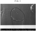
- Figs. 1 , 2 , and 3 are SEM photographs of the cross sections of the twisted carbon nanotube yarns obtained in Example 1 and Comparative Examples 1 and 4, respectively.
- Void fraction [%] (area of void portion/cross-sectional area of twisted carbon nanotube yarn) ⁇ 100
- the binarization was performed in the following manner. That is, the SEM photograph image was cropped to leave the cross-sectional area portion of the yarn. The cross-sectional area portion and the hole area portion were separated by adjusting brightness, contrast, and mid-tones. The number of pixels was counted using binarization software on the cross-sectional area portion and the hole area portion, respectively to calculate the cross-sectional area and the void portion area of the twisted carbon nanotube yarn.
- the electrical conductivity of the twisted carbon nanotube yarn was calculated by measuring the diameter ( ⁇ m) and line resistance ( ⁇ /cm) of the twisted carbon nanotube yarn and converting them into electrical conductivity per cross-sectional area.
- Example 1 As described above, it was found that the twisted carbon nanotube yarn obtained in Example 1 had a lower void fraction, higher electrical conductivity, and higher tensile strength than those of the carbon nanotube yarn obtained in Comparative Example 1. This indicated that the invention provided the twisted carbon nanotube yarn having excellent strength and electrical conductive properties.
Landscapes
- Engineering & Computer Science (AREA)
- Chemical & Material Sciences (AREA)
- Textile Engineering (AREA)
- Organic Chemistry (AREA)
- Mechanical Engineering (AREA)
- Materials Engineering (AREA)
- Nanotechnology (AREA)
- Inorganic Chemistry (AREA)
- Physics & Mathematics (AREA)
- Thermal Sciences (AREA)
- Chemical Kinetics & Catalysis (AREA)
- General Chemical & Material Sciences (AREA)
- Yarns And Mechanical Finishing Of Yarns Or Ropes (AREA)
Abstract
Description
- The present invention relates to a method for manufacturing a twisted carbon nanotube yarn.
- Carbon nanotubes have excellent mechanical properties, electrical properties, thermal properties, or the like, and are expected to be used in industries, such as field emission displays or conductive fillers. In particular, a twisted carbon nanotube yarn made by spinning carbon nanotube fibers is expected to be used.
- A twisted carbon nanotube yarn is produced by twisting a sheet of carbon nanotubes drawn in yarn form from a carbon nanotube substrate. However, in the case of producing a twisted carbon nanotube yarn, the strength of the carbon nanotube sheet drawn from the carbon nanotube substrate is low. This resulted in a problem that when the carbon nanotubes drawn from the substrate were strongly twisted, the fibers broke. In addition, the twisted carbon nanotube yarn produced as described above was very thin. This resulted in a problem that the yarn had insufficient tensile strength and electrical conductivity. To solve such problems, for example, Patent Literature 1 describes a method for manufacturing a twisted carbon nanotube yarn, in which a twisted yarn containing carbon nanotubes is irradiated with an electron beam.
- Patent Literature 1:
Japanese Unexamined Patent Application Publication No. 2011-153392 - However, in the method described in Patent Literature 1, the strength of the carbon nanotube sheet drawn from the substrate remains weak. Thus, it is not possible to strongly twist the carbon nanotube sheet drawn from the substrate. Further, insufficient twisting fails to improve the density of the twisted carbon nanotube yarn, resulting in a decrease in electrical conductive properties.
- It is an object of the invention to provide a method for manufacturing a twisted carbon nanotube yarn having excellent strength and electrical conductive properties.
-
- [1] A method for manufacturing a twisted carbon nanotube yarn, including: drawing carbon nanotubes in sheet form from an end portion of a carbon nanotube forest to provide a carbon nanotube sheet; performing false twisting by twisting the carbon nanotube sheet and then performing untwisting to provide a carbon nanotube linear body; and twisting the carbon nanotube linear body to provide a twisted carbon nanotube yarn, in which the number of twists when the carbon nanotube sheet is false-twisted in the false twisting is in a range from 300 T/m to 5,000 T/m, and the number of twists when the carbon nanotube linear body is twisted in the providing of the twisted carbon nanotube yarn is in a range from 900 T/m to 5,000 T/m.
- [2] In the method for manufacturing a twisted carbon nanotube yarn according to [1], a void fraction of the twisted carbon nanotube yarn is in a range from 0% to 1%.
- [3] In the method for manufacturing a twisted carbon nanotube yarn according to [1] or [2], electrical conductivity of the twisted carbon nanotube yarn is in a range from 6.0 × 10² S/cm to 6.3 × 10⁵ S/cm.
- [4] In the method for manufacturing a twisted carbon nanotube yarn according to any of [1] to [3], a tensile strength of the twisted carbon nanotube yarn is in a range from 750 MPa to 5,000 MPa.
- According to the aspect of the invention, it is possible to provide a method for manufacturing a twisted carbon nanotube yarn having excellent strength and electrical conductive properties.
-
-
Fig. 1 is a SEM photograph of a cross section of a twisted carbon nanotube yarn obtained in Example 1. -
Fig. 2 is a SEM photograph of a cross section of a twisted carbon nanotube yarn obtained in Comparative Example 1. -
Fig. 3 is a SEM photograph of a cross section of a twisted carbon nanotube yarn obtained in Comparative Example 4. - Hereinafter, an exemplary embodiment of the invention will be described.
- A method for manufacturing a twisted carbon nanotube yarn according to the exemplary embodiment includes a step of drawing carbon nanotubes in sheet form from an end portion of a carbon nanotube forest to provide a carbon nanotube sheet (drawing step), a step of performing a false twisting step of twisting the carbon nanotube sheet and then performing untwisting to provide a carbon nanotube linear body (false twisting step), and a step of twisting the carbon nanotube linear body to provide a twisted carbon nanotube yarn (main twisting step).
- In the exemplary embodiment, the false twisting step of twisting the carbon nanotube sheet and then performing untwisting is performed. This can increase the strength of the carbon nanotube linear body before the main twisting step. Thus, even if the carbon nanotube linear body is strongly twisted in the main twisting step, the fibers can be prevented from breaking. According to the exemplary embodiment, a twisted carbon nanotube yarn sufficiently twisted can be produced, and a twisted carbon nanotube yarn having excellent strength and electrical conductive properties can be manufactured.
- In the drawing step, a carbon nanotube forest is prepared.
- The carbon nanotube forest can be produced, for example, by a chemical vapor deposition method or by a method in which carbon nanotubes grow in a cotton-like form in air. Among these, from the viewpoint of the quality of the resulting carbon nanotubes, carbon nanotubes are preferably manufactured by the chemical vapor deposition method. The carbon nanotube forest is exemplified by a carbon nanotube assembly grown by chemical vapor deposition on a substrate.
- As the substrate, any known substrate can be used as appropriate. For example, a plastic substrate, a glass substrate, a silicon substrate, or a metal substrate containing a metal such as iron or copper or an alloy thereof can be used. A silicon dioxide film may be stacked on a surface of any of these substrates.
- The carbon nanotubes grown by chemical vapor deposition on the substrate may be single-walled carbon nanotubes, double-walled carbon nanotubes, multi-walled carbon nanotubes, or a mixture thereof.
- The form of the carbon nanotube assembly is not particularly limited. From the viewpoint of facilitating the formation of twisted carbon nanotube yarn, a high-density, highly oriented assembly formed on a substrate is preferred. The carbon nanotubes on the substrate preferably have a bulk density of 20 mg/cm3 or more. When the bulk density is 20 mg/cm3 or more, the drawability can be improved. The term "highly oriented" indicates that the carbon nanotubes are adjacent to each other and oriented perpendicular to a planar surface of the substrate.
- The height (length) of the carbon nanotubes in the carbon nanotube assembly is preferably, on average, 100 µm or more, and more preferably 150 µm or more. The number of layers of the carbon nanotubes in the carbon nanotube assembly may be one or more, and is preferably in a range from 1 to 40.
- In the drawing step, carbon nanotubes are drawn in sheet form from an end portion of the carbon nanotube forest to provide a carbon nanotube sheet.
- The carbon nanotube sheet can be drawn with a known drawing tool.
- The width of the carbon nanotube sheet is preferably in a range from 20 mm to 200 mm, more preferably in a range from 25 mm to 100 mm.
- In the false twisting step, the false twisting step of twisting the carbon nanotube sheet obtained in the drawing step and then performing untwisting is performed, thereby providing a carbon nanotube linear body.
- As a method for twisting the carbon nanotube sheet, a known method can be employed. For example, the carbon nanotube sheet can be twisted by rotating a roller or the like holding the carbon nanotube sheet. The carbon nanotube sheet may be twisted by winding it on a roller or the like.
- As a method for untwisting the twisted carbon nanotube sheet, a known method can be employed. For example, a roller or the like holding the twisted carbon nanotube sheet can be rotated in the opposite direction to that in which the twisting was performed, thereby untwisting the carbon nanotube sheet. The twisted carbon nanotube sheet may be untwisted by pulling the sheet back from the roller or the like on which the sheet is wound. That is, in the case of performing twisting with a roller or the like, when the roller twists the sheet clockwise, the sheet on the outlet side naturally has a counterclockwise twist and returns to zero twist (no twist). It is preferable to ensure a path line long enough to allow the twist to return naturally.
- The number of twists when the carbon nanotube sheet is false-twisted in the false twisting step needs to be in a range from 300 T/m to 5,000 T/m, preferably in a range from 500 T/m to 5,000 T/m, and more preferably in a range from 700 T/m to 5,000 T/m.
- The number of twists when the false-twisted carbon nanotube sheet is untwisted is preferably in a range from 300 T/m to 5,000 T/m, more preferably in a range from 500 T/m to 5,000 T/m, and still more preferably in a range from 700 T/m to 5,000 T/m.
- When the number of twists is within the above range, the strength of the carbon nanotube linear body can be increased.
- In the main twisting step, the carbon nanotube linear body obtained in the false twisting step is twisted to provide a twisted carbon nanotube yarn.
- As a method for twisting the carbon nanotube sheet linear body, a known method can be employed. For example, the carbon nanotube linear body can be twisted by rotating a roller or the like holding the carbon nanotube linear body.
- In the main twisting step, the twisted carbon nanotube yarn is wound on a bobbin. At this time, although the twisted carbon nanotube yarn is pulled, the carbon nanotube linear body can be prevented from breaking, this is because the strength of the carbon nanotube linear body has been improved in the false twisting step.
- The number of twists when the carbon nanotube linear body is twisted needs to be in a range from 900 T/m to 5,000 T/m, more preferably in a range from 1,000 T/m to 3,000 T/m, and still more preferably 1,000 T/m to 2,000 T/m.
- In this way, the twisted carbon nanotube yarn according to the exemplary embodiment is obtained. The resulting twisted carbon nanotube yarn preferably satisfies the following requirements.
- From the viewpoint of strength and handleability of the twisted carbon nanotube yarn, the diameter of the twisted carbon nanotube yarn is preferably in a range from 1 µm to 1,000 µm, more preferably in a range from 15 µm to 100 µm, and still more preferably in a range from 25 µm to 75 µm.
- From the viewpoint of strength of the twisted carbon nanotube yarn, the twist angle of the twisted carbon nanotube yarn is preferably in a range from 8 degrees to 50 degrees, more preferably in a range from 10 degrees to 30 degrees. The twist angle can be adjusted by the number of twists when the carbon nanotube linear body is twisted. The twist may be untwisted after the main twisting step so that the twist angle falls within the above range.
- The void fraction of the twisted carbon nanotube yarn is preferably in a range from 0% to 1%, more preferably in a range from 0% to 0.5%. When the void fraction is within the above range, the strength and electrical conductive properties of the twisted carbon nanotube yarn can be improved.
- The void fraction of the twisted carbon nanotube yarn can be measured by image analysis of a scanning electron microscope (SEM) photograph.
- Specifically, the void fraction can be calculated by observing a cross section of the twisted carbon nanotube yarn with a SEM and binarizing a carbon nanotube portion and a void portion.
Void fraction [%] = (area of void portion/cross-sectional area of twisted carbon nanotube yarn) × 100 - From the viewpoint of the electrical conductive properties of the twisted carbon nanotube yarn, the electrical conductivity of the twisted carbon nanotube yarn is preferably in a range from 6.0 × 10² S/cm to 6.3 × 10⁵ S/cm.
- The electrical conductivity of the twisted carbon nanotube yarn can be calculated by measuring the diameter (µm) and line resistance (Ω/cm) of the twisted carbon nanotube yarn and converting them into electrical conductivity per cross-sectional area.
- From the viewpoint of the strength of the twisted carbon nanotube yarn, the tensile strength of the twisted carbon nanotube yarn is preferably in a range from 750 MPa to 5,000 MPa, more preferably in a range from 1,000 MPa to 5,000 MPa.
- The tensile strength of the twisted carbon nanotube yarn can be measured by a method described in JIS L1095.
- The scope of the invention is not limited to the above exemplary embodiment, and modifications, improvements, etc. are included within the scope of the invention as long as they are compatible with an object of the invention.
- While the invention will be described in more detail below with reference to examples, the invention is not limited to these examples.
- A carbon nanotube forest was cut so as to have a width of 33 mm. From an end portion thereof, the carbon nanotubes were drawn in sheet form (width: 33 mm) in a direction in which the deviation from the parallel direction of the carbon nanotube forest was within 10 degrees, thereby providing a carbon nanotube sheet. The resulting carbon nanotube sheet was bundled in yarn form using a guide, and a false twisting step was performed by twisting the yarn-like carbon nanotube (the number of twists: 1,000 T/m) and untwisting it (allowing it to return naturally), thereby providing a carbon nanotube linear body. The resulting carbon nanotube linear body was twisted (the number of twists: 1,200 T/m) and wound on a bobbin to provide a twisted carbon nanotube yarn.
- A carbon nanotube forest was cut so as to have a width of 33 mm. From an end portion thereof, the carbon nanotubes were drawn in sheet form (width: 33 mm) in a direction in which the deviation from the parallel direction of the carbon nanotube forest was within 10 degrees, thereby providing a carbon nanotube sheet. The resulting carbon nanotube sheet was bundled in yarn form using a guide. The yarn-like carbon nanotube was twisted (the number of twists: 1,000 T/m) and then untwisted (naturally returned), thereby providing a carbon nanotube yarn.
- A carbon nanotube forest was cut so as to have a width of 33 mm. From an end portion thereof, the carbon nanotubes were drawn in sheet form (width: 33 mm) in a direction in which the deviation from the parallel direction of the carbon nanotube forest was within 10 degrees, thereby providing a carbon nanotube sheet. The resulting carbon nanotube sheet was bundled in yarn form using a guide. The yarn-like carbon nanotube was twisted (the number of twists: 1,200 T/m) and wound on a bobbin. At this time, the twisted carbon nanotube yarn was broken, thus failing to produce the twisted carbon nanotube yarn.
- A carbon nanotube forest was cut so as to have a width of 33 mm. From an end portion thereof, the carbon nanotubes were drawn in sheet form (width: 33 mm) in a direction in which the deviation from the parallel direction of the carbon nanotube forest was within 10 degrees, thereby providing a carbon nanotube sheet. The resulting carbon nanotube sheet was bundled in yarn form using a guide, thereby providing a yarn-like carbon nanotube.
- A carbon nanotube forest was cut so as to have a width of 33 mm. From an end portion thereof, the carbon nanotubes were drawn in sheet form (width: 33 mm) in a direction in which the deviation from the parallel direction of the carbon nanotube forest was within 10 degrees, thereby providing a carbon nanotube sheet. The resulting carbon nanotube sheet was bundled in yarn form using a guide, and a false twisting step was performed by twisting the yarn-like carbon nanotube (the number of twists: 1,000 T/m) and untwisting it (allowing it to return naturally), thereby providing a carbon nanotube linear body. The resulting carbon nanotube linear body was twisted (the number of twists: 800 T/m) and wound on a bobbin to provide a twisted carbon nanotube yarn.
- A carbon nanotube forest was cut so as to have a width of 33 mm. From an end portion thereof, the carbon nanotubes were drawn in sheet form (width: 33 mm) in a direction in which the deviation from the parallel direction of the carbon nanotube forest was within 10 degrees, thereby providing a carbon nanotube sheet. The resulting carbon nanotube sheet was bundled in yarn form using a guide, and a false twisting step was performed by twisting the yarn-like carbon nanotube (the number of twists: 250 T/m) and untwisting it (allowing it to return naturally), thereby providing a carbon nanotube linear body. The resulting carbon nanotube linear body was twisted (the number of twists: 1,200 T/m) and wound on a bobbin. At this time, the twisted carbon nanotube yarn was broken, thus failing to produce the twisted carbon nanotube yarn.
- The carbon nanotube yarns obtained in Example 1 and Comparative Examples 1 to 5 were evaluated in terms of the void fraction, electrical conductivity, and tensile strength. Table 1 presents the obtained results. In Comparative Examples 2 and 5, no evaluation was performed because the twisted carbon nanotube yarn was not produced. In Comparative Example 3, the void fraction was not evaluated.
- The void fraction of the twisted carbon nanotube yarn was measured by image analysis of a SEM photograph. Specifically, the void fraction was calculated by observing a cross section of the twisted carbon nanotube yarn with a SEM and binarizing a carbon nanotube portion and a void portion.
Figs. 1 ,2 , and3 are SEM photographs of the cross sections of the twisted carbon nanotube yarns obtained in Example 1 and Comparative Examples 1 and 4, respectively.Void fraction [%] = (area of void portion/cross-sectional area of twisted carbon nanotube yarn) × 100 - Specifically, the binarization was performed in the following manner. That is, the SEM photograph image was cropped to leave the cross-sectional area portion of the yarn. The cross-sectional area portion and the hole area portion were separated by adjusting brightness, contrast, and mid-tones. The number of pixels was counted using binarization software on the cross-sectional area portion and the hole area portion, respectively to calculate the cross-sectional area and the void portion area of the twisted carbon nanotube yarn.
- The electrical conductivity of the twisted carbon nanotube yarn was calculated by measuring the diameter (µm) and line resistance (Ω/cm) of the twisted carbon nanotube yarn and converting them into electrical conductivity per cross-sectional area.
- The tensile strength was measured according to a method described in JIS L1095.
Table 1 Void fraction (%) Electrical conductivity (S/cm) Tensile strength (MPa) Example 1 0.11 957 1348 Comparative Example 1 3.14 564 949 Comparative Example 2 - - - Comparative Example 3 - 76 80 Comparative Example 4 1.87 372 623 Comparative Example 5 - - - - As described above, it was found that the twisted carbon nanotube yarn obtained in Example 1 had a lower void fraction, higher electrical conductivity, and higher tensile strength than those of the carbon nanotube yarn obtained in Comparative Example 1. This indicated that the invention provided the twisted carbon nanotube yarn having excellent strength and electrical conductive properties.
Claims (4)
- A method for manufacturing a twisted carbon nanotube yarn, comprising:drawing carbon nanotubes in sheet form from an end portion of a carbon nanotube forest to provide a carbon nanotube sheet;performing false twisting by twisting the carbon nanotube sheet and then performing untwisting to provide a carbon nanotube linear body; andtwisting the carbon nanotube linear body to provide a twisted carbon nanotube yarn,wherein the number of twists when the carbon nanotube sheet is false-twisted in the false twisting is in a range from 300 T/m to 5,000 T/m, andthe number of twists when the carbon nanotube linear body is twisted in the providing of the twisted carbon nanotube yarn is in a range from 900 T/m to 5,000 T/m.
- The method for manufacturing a twisted carbon nanotube yarn according to claim 1,
wherein a void fraction of the twisted carbon nanotube yarn is in a range from 0% to 1%. - The method for manufacturing a twisted carbon nanotube yarn according to claim 1 or 2,
wherein electrical conductivity of the twisted carbon nanotube yarn is in a range from 6.0 × 10² S/cm to 6.3 × 10⁵ S/cm. - The method for manufacturing a twisted carbon nanotube yarn according to claim 1 or 2,
wherein a tensile strength of the twisted carbon nanotube yarn is in a range from 750 MPa to 5,000 MPa.
Applications Claiming Priority (2)
| Application Number | Priority Date | Filing Date | Title |
|---|---|---|---|
| JP2022072377 | 2022-04-26 | ||
| PCT/JP2023/012782 WO2023210248A1 (en) | 2022-04-26 | 2023-03-29 | Method for manufacturing carbon nanotube twisted yarn |
Publications (2)
| Publication Number | Publication Date |
|---|---|
| EP4516976A1 true EP4516976A1 (en) | 2025-03-05 |
| EP4516976A4 EP4516976A4 (en) | 2026-04-29 |
Family
ID=88518635
Family Applications (1)
| Application Number | Title | Priority Date | Filing Date |
|---|---|---|---|
| EP23795995.2A Pending EP4516976A4 (en) | 2022-04-26 | 2023-03-29 | METHOD FOR PRODUCING A TWISTED CARBON NANOTUB YARN |
Country Status (6)
| Country | Link |
|---|---|
| EP (1) | EP4516976A4 (en) |
| JP (1) | JPWO2023210248A1 (en) |
| KR (1) | KR20250003535A (en) |
| CN (1) | CN119053735A (en) |
| TW (1) | TW202409371A (en) |
| WO (1) | WO2023210248A1 (en) |
Family Cites Families (7)
| Publication number | Priority date | Publication date | Assignee | Title |
|---|---|---|---|---|
| CN108425170B (en) * | 2004-11-09 | 2021-02-26 | 得克萨斯大学体系董事会 | Manufacture and use of nanofiber yarns, tapes and sheets |
| JP5429751B2 (en) | 2010-01-28 | 2014-02-26 | 地方独立行政法人大阪府立産業技術総合研究所 | Carbon nanotube twisted yarn and method for producing the same |
| CN102953171A (en) * | 2011-08-30 | 2013-03-06 | 苏州捷迪纳米科技有限公司 | Carbon nanotube spinning machine and method for preparing carbon nanotube yarns by use of same |
| EP3018242B1 (en) * | 2013-07-05 | 2019-10-23 | Murata Machinery, Ltd. | Yarn manufacturing apparatus |
| WO2015001668A1 (en) * | 2013-07-05 | 2015-01-08 | 村田機械株式会社 | Yarn manufacturing apparatus |
| WO2018118682A1 (en) * | 2016-12-19 | 2018-06-28 | Lintec Of America, Inc. | Nanofiber yarn spinning system |
| JP7372092B2 (en) * | 2019-09-18 | 2023-10-31 | 日立造船株式会社 | Manufacturing method of carbon nanotube twisted yarn |
-
2023
- 2023-03-29 KR KR1020247032776A patent/KR20250003535A/en active Pending
- 2023-03-29 WO PCT/JP2023/012782 patent/WO2023210248A1/en not_active Ceased
- 2023-03-29 EP EP23795995.2A patent/EP4516976A4/en active Pending
- 2023-03-29 CN CN202380034354.5A patent/CN119053735A/en active Pending
- 2023-03-29 JP JP2024517919A patent/JPWO2023210248A1/ja active Pending
- 2023-04-11 TW TW112113404A patent/TW202409371A/en unknown
Also Published As
| Publication number | Publication date |
|---|---|
| TW202409371A (en) | 2024-03-01 |
| EP4516976A4 (en) | 2026-04-29 |
| WO2023210248A1 (en) | 2023-11-02 |
| JPWO2023210248A1 (en) | 2023-11-02 |
| CN119053735A (en) | 2024-11-29 |
| KR20250003535A (en) | 2025-01-07 |
Similar Documents
| Publication | Publication Date | Title |
|---|---|---|
| Miao | Yarn spun from carbon nanotube forests: production, structure, properties and applications | |
| Miao et al. | Poisson’s ratio and porosity of carbon nanotube dry-spun yarns | |
| EP1273685B1 (en) | Carbon fiber sheet and method for producing the same | |
| US20210002794A1 (en) | Method for producing carbon nanotube yarn | |
| EP3431529B1 (en) | Molded article of fiber-reinforced resin and compression molding method | |
| Alvarez et al. | Tailoring physical properties of carbon nanotube threads during assembly | |
| US20180237295A1 (en) | Electric wire of carbon nanotube twisted yarn and method for producing the same | |
| US20160032499A1 (en) | Methods of making nanofiber yarns and threads | |
| EP2060525A1 (en) | Carbon fiber package and process for producing the same | |
| WO2008095239A1 (en) | Nanofibre yarns | |
| JPWO2016080526A1 (en) | Carbon nanotube sheet manufacturing method and carbon nanotube sheet | |
| EP3904285A1 (en) | Carbon nanotube production method, carbon nanotube assembly wire production method, carbon nanotube assembly wire bundle production method, carbon nanotube production device, carbon nanotube assembly wire production device and carbon nanotube assembly wire bundle production device | |
| Biró et al. | Scanning tunneling microscopy observation of tightly wound, single-wall coiled carbon nanotubes | |
| JP2019049077A (en) | Method of manufacturing carbon nanotube wire | |
| US20200258648A1 (en) | Carbon nanotube strand wire, coated carbon nanotube electric wire, and wire harness | |
| EP3763856B1 (en) | Carbon fiber and method for manufacturing same | |
| Kikuchi et al. | Ultra-fine Nb 3 Al mono-core wires and cables | |
| EP4033018A1 (en) | Method for manufacturing carbon nanotube twisted thread, and device for manufacturing carbon nanotube twisted thread | |
| EP0969140B1 (en) | Steel cords for the reinforcement of rubber articles | |
| KR20250003535A (en) | Method for producing carbon nanotube yarn | |
| EP3623342B1 (en) | Method for producing a carbon nanotube array, and for producing a spun carbon nanotube yarn | |
| CN1796623B (en) | Composite fiber with excellent conductivity and method for manufacturing same | |
| EP4682063A1 (en) | Ribbon, tether material, tether, method for manufacturing ribbon, method for manufacturing tether material, and method for manufacturing tether | |
| US6416876B1 (en) | Copper matrix composites | |
| JP2005171453A (en) | Method for manufacturing stretch spun yarn |
Legal Events
| Date | Code | Title | Description |
|---|---|---|---|
| STAA | Information on the status of an ep patent application or granted ep patent |
Free format text: STATUS: THE INTERNATIONAL PUBLICATION HAS BEEN MADE |
|
| PUAI | Public reference made under article 153(3) epc to a published international application that has entered the european phase |
Free format text: ORIGINAL CODE: 0009012 |
|
| STAA | Information on the status of an ep patent application or granted ep patent |
Free format text: STATUS: REQUEST FOR EXAMINATION WAS MADE |
|
| 17P | Request for examination filed |
Effective date: 20241008 |
|
| AK | Designated contracting states |
Kind code of ref document: A1 Designated state(s): AL AT BE BG CH CY CZ DE DK EE ES FI FR GB GR HR HU IE IS IT LI LT LU LV MC ME MK MT NL NO PL PT RO RS SE SI SK SM TR |
|
| DAV | Request for validation of the european patent (deleted) | ||
| DAX | Request for extension of the european patent (deleted) | ||
| A4 | Supplementary search report drawn up and despatched |
Effective date: 20260401 |
|
| RIC1 | Information provided on ipc code assigned before grant |
Ipc: D02G 3/26 20060101AFI20260326BHEP Ipc: C01B 32/168 20170101ALI20260326BHEP Ipc: D01F 9/127 20060101ALI20260326BHEP Ipc: D02G 3/16 20060101ALI20260326BHEP |