EP4516725A1 - Sensor, sensor system, and electronic device - Google Patents
Sensor, sensor system, and electronic device Download PDFInfo
- Publication number
- EP4516725A1 EP4516725A1 EP24179531.9A EP24179531A EP4516725A1 EP 4516725 A1 EP4516725 A1 EP 4516725A1 EP 24179531 A EP24179531 A EP 24179531A EP 4516725 A1 EP4516725 A1 EP 4516725A1
- Authority
- EP
- European Patent Office
- Prior art keywords
- annular
- connect
- annular portion
- fixed
- radial direction
- Prior art date
- Legal status (The legal status is an assumption and is not a legal conclusion. Google has not performed a legal analysis and makes no representation as to the accuracy of the status listed.)
- Pending
Links
Images


Classifications
-
- B—PERFORMING OPERATIONS; TRANSPORTING
- B81—MICROSTRUCTURAL TECHNOLOGY
- B81B—MICROSTRUCTURAL DEVICES OR SYSTEMS, e.g. MICROMECHANICAL DEVICES
- B81B3/00—Devices comprising flexible or deformable elements, e.g. comprising elastic tongues or membranes
- B81B3/0035—Constitution or structural means for controlling the movement of the flexible or deformable elements
- B81B3/004—Angular deflection
- B81B3/0045—Improve properties related to angular swinging, e.g. control resonance frequency
-
- G—PHYSICS
- G01—MEASURING; TESTING
- G01C—MEASURING DISTANCES, LEVELS OR BEARINGS; SURVEYING; NAVIGATION; GYROSCOPIC INSTRUMENTS; PHOTOGRAMMETRY OR VIDEOGRAMMETRY
- G01C19/00—Gyroscopes; Turn-sensitive devices using vibrating masses; Turn-sensitive devices without moving masses; Measuring angular rate using gyroscopic effects
- G01C19/56—Turn-sensitive devices using vibrating masses, e.g. vibratory angular rate sensors based on Coriolis forces
- G01C19/567—Turn-sensitive devices using vibrating masses, e.g. vibratory angular rate sensors based on Coriolis forces using the phase shift of a vibration node or antinode
- G01C19/5677—Turn-sensitive devices using vibrating masses, e.g. vibratory angular rate sensors based on Coriolis forces using the phase shift of a vibration node or antinode of essentially two-dimensional [2D] vibrators, e.g. ring-shaped vibrators
- G01C19/5684—Turn-sensitive devices using vibrating masses, e.g. vibratory angular rate sensors based on Coriolis forces using the phase shift of a vibration node or antinode of essentially two-dimensional [2D] vibrators, e.g. ring-shaped vibrators the devices involving a micromechanical structure
-
- G—PHYSICS
- G01—MEASURING; TESTING
- G01C—MEASURING DISTANCES, LEVELS OR BEARINGS; SURVEYING; NAVIGATION; GYROSCOPIC INSTRUMENTS; PHOTOGRAMMETRY OR VIDEOGRAMMETRY
- G01C19/00—Gyroscopes; Turn-sensitive devices using vibrating masses; Turn-sensitive devices without moving masses; Measuring angular rate using gyroscopic effects
- G01C19/56—Turn-sensitive devices using vibrating masses, e.g. vibratory angular rate sensors based on Coriolis forces
- G01C19/5705—Turn-sensitive devices using vibrating masses, e.g. vibratory angular rate sensors based on Coriolis forces using masses driven in reciprocating rotary motion about an axis
- G01C19/5712—Turn-sensitive devices using vibrating masses, e.g. vibratory angular rate sensors based on Coriolis forces using masses driven in reciprocating rotary motion about an axis the devices involving a micromechanical structure
-
- G—PHYSICS
- G01—MEASURING; TESTING
- G01P—MEASURING LINEAR OR ANGULAR SPEED, ACCELERATION, DECELERATION, OR SHOCK; INDICATING PRESENCE, ABSENCE, OR DIRECTION, OF MOVEMENT
- G01P15/00—Measuring acceleration; Measuring deceleration; Measuring shock, i.e. sudden change of acceleration
- G01P15/02—Measuring acceleration; Measuring deceleration; Measuring shock, i.e. sudden change of acceleration by making use of inertia forces using solid seismic masses
- G01P15/08—Measuring acceleration; Measuring deceleration; Measuring shock, i.e. sudden change of acceleration by making use of inertia forces using solid seismic masses with conversion into electric or magnetic values
- G01P15/125—Measuring acceleration; Measuring deceleration; Measuring shock, i.e. sudden change of acceleration by making use of inertia forces using solid seismic masses with conversion into electric or magnetic values by capacitive pick-up
-
- B—PERFORMING OPERATIONS; TRANSPORTING
- B81—MICROSTRUCTURAL TECHNOLOGY
- B81B—MICROSTRUCTURAL DEVICES OR SYSTEMS, e.g. MICROMECHANICAL DEVICES
- B81B2201/00—Specific applications of microelectromechanical systems
- B81B2201/02—Sensors
- B81B2201/0228—Inertial sensors
- B81B2201/0242—Gyroscopes
-
- B—PERFORMING OPERATIONS; TRANSPORTING
- B81—MICROSTRUCTURAL TECHNOLOGY
- B81B—MICROSTRUCTURAL DEVICES OR SYSTEMS, e.g. MICROMECHANICAL DEVICES
- B81B2203/00—Basic microelectromechanical structures
- B81B2203/04—Electrodes
-
- B—PERFORMING OPERATIONS; TRANSPORTING
- B81—MICROSTRUCTURAL TECHNOLOGY
- B81B—MICROSTRUCTURAL DEVICES OR SYSTEMS, e.g. MICROMECHANICAL DEVICES
- B81B2203/00—Basic microelectromechanical structures
- B81B2203/05—Type of movement
- B81B2203/056—Rotation in a plane parallel to the substrate
Definitions
- Embodiments described herein relate generally to a sensor, a sensor system, and an electronic device.
- sensors having a MEMS (Micro Electro Mechanical Systems) structure.
- electronic devices and the like are controlled based on information obtained by sensors. It is desired to improve the characteristics of sensors.
- a sensor includes a base including a first face, a fixed portion fixed to the first face, and a movable portion supported by the fixed portion. A gap is provided between the first face and the movable portion.
- the movable portion includes a plurality of annular portions and a plurality of connect portions. Each of the plurality of annular portions is provided around the fixed portion with the fixed portion as a center on a first plane along the first face.
- the plurality of annular portions includes a first annular portion, a second annular portion, and a third annular portion.
- the second annular portion is provided between the first annular portion and the fixed portion.
- the third annular portion is provided between the second annular portion and the fixed portion. The second annular portion is next to the first annular portion.
- the third annular portion is next to the second annular portion.
- the plurality of connect portions includes a first connect portion and a second connect portion.
- the first connect portion is provided between the first annular portion and the second annular portion, and is connected to the first annular portion and the second annular portion.
- the second connect portion is provided between the second annular portion and the third annular portion, and is connected to the second annular portion and the third annular portion.
- the first connect portion and the second connect portion are along a first radial direction. The first radial direction passes through a first center of the fixed portion on the first plane and is along the first plane.
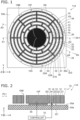
- FIG. 1 is a schematic plan view illustrating a sensor according to a first embodiment.
- FIGS. 2 and 3 are schematic cross-sectional views illustrating the sensor according to the first embodiment.
- FIG. 2 is a sectional view taken along the line A1-A2 in FIG. 1 .
- FIG. 3 is a sectional view taken along the line A3-A4 in FIG. 1 .
- a sensor 110 includes a base 50s, a fixed portion 10F, and a movable portion 10M.
- the base 50s includes a first face 50a.
- the fixed portion 10F is fixed to the first face 50a.
- the movable portion 10M is supported by the fixed portion 10F.
- a gap G1 is provided between the first face 50a and the movable portion 10M.
- an insulating member 55 is provided on the first face 50a.
- the fixed portion 10F is provided on the insulating member 55.
- the insulating member 55 is not provided between the first face 50a and the movable portion 10M.
- the movable portion 10M is electrically conductive.
- the movable portion 10M may include, for example, conductive silicon.
- the fixed portion 10F is electrically conductive.
- the fixed portion 10F may include, for example, conductive silicon.
- the fixed portion 10F is electrically connected to the movable portion 10M.
- the insulating member 55 may include, for example, silicon oxide.
- the movable portion 10M includes a plurality of annular portions 10 and a plurality of connect portions 20. Each of the plurality of annular portions 10 is provided around the fixed portion 10F with the fixed portion 10F as a center on a first plane PL1 along the first face 50a.
- a direction perpendicular to the first plane PL1 is defined as a Z-axis direction.
- One direction perpendicular to the Z-axis direction is defined as an X-axis direction.
- a direction perpendicular to the Z-axis direction and the X-axis direction is defined as a Y-axis direction.
- the first plane PL1 is parallel to the X-Y plane.
- each of the plurality of annular portions 10 is concentric with the fixed portion 10F as the center.
- Each of the plurality of annular portions 10 extends along a circumferential direction of the circle.
- the plurality of annular portions 10 include a first annular portion 11, a second annular portion 12, and a third annular portion 13.
- the plurality of annular portions 10 may further include a fourth annular portion 14, a fifth annular portion 15, and the like.
- the number of the plurality of annular portions 10 is arbitrary.
- the second annular portion 12 is provided between the first annular portion 11 and the fixed portion 10F.
- the third annular portion 13 is provided between the second annular portion 12 and the fixed portion 10F.
- the second annular portion 12 is next to the first annular portion 11 among the plurality of annular portions 10.
- the third annular portion 13 is next to the second annular portion 12 among the plurality of annular portions 10.
- the second annular portion 12 is closest to the first annular portion 11 among the plurality of annular portions 10.
- the third annular portion 13 is closest to the second annular portion 12 among the plurality of annular portions 10.
- the plurality of connect portions 20 include a first connect portion 21 and a second connect portion 22.
- the plurality of connect portions 20 may include a third connect portion 23, a fourth connect portion 24, and the like.
- the number of the plurality of connect portions 20 is arbitrary.
- the first connect portion 21 is provided between the first annular portion 11 and the second annular portion 12.
- the first connect portion 21 is connected to the first annular portion 11 and the second annular portion 12.
- the second connect portion 22 is provided between the second annular portion 12 and the third annular portion 13.
- the second connect portion 22 is connected to the second annular portion 12 and the third annular portion 13.
- the first connect portion 21 and the second connect portion 22 are along a first radial direction Dr1.
- the first radial direction Dr1 passes through a first center 10C of the fixed portion 10F on the first plane PL1 and extends along the first plane PL1.
- the first radial direction Dr1 is the X-axis direction.
- a plurality of fixed electrodes 30 are provided in the sensor 110.
- the plurality of fixed electrodes 30 are fixed to the first face 50a.
- a signal including an alternating component is applied between the plurality of fixed electrodes 30 and the movable portion 10M.
- the alternating component may have, for example, a frequency component that excites the resonant vibration of the movable portion 10M.
- the vibration state changes.
- the applied external force can be detected.
- the change in the vibration state is detected as a change in capacitance, for example.
- the change in the vibration state due to external forces are caused by, for example, Coriolis force.
- the change in the vibration state can be detected, for example, by another part of the plurality of fixed electrodes 30.
- the signal may be supplied by the controller 70, for example.
- the controller 70 may detect the change in the vibration state.
- At least three of the annular portions 10 adjacent to each other are connected by the connect portions 20 along the first radial direction Dr1.
- the portions of three of the annular portions 10 connected by the connect portions 20 vibrate in conjunction with each other. This results in a high intensity signal regarding vibrations.
- At least three of the annular portions 10 adjacent to each other are linearly connected.
- the plurality of annular portions 10 adjacent to each other are not connected linearly.
- the direction in which the first connect portion 21 extends crosses the direction in which the second connect portion 22 extends.
- the coupling between the plurality of annular portions 10 adjacent to each other is weak.
- the positions where the plurality of annular portions 10 are connected are averaged.
- the plurality of annular portions 10 adjacent to each other do not vibrate in conjunction with each other. Therefore, the strength of the detected signal is low.
- At least three of the annular portions 10 adjacent to each other are connected by the connect portions 20 along the first radial direction Dr1. At least three of the annular portions 10 vibrate in conjunction. Thereby, high intensity signal can be detected. For example, high sensitivity can be obtained. For example, a high S/N ratio can be obtained. According to the embodiment, a sensor whose characteristics can be improved can be provided.
- entire of the movable portion 10M has a honeycomb structure.
- the direction in which the connect portions 20 extends is not the radial direction.
- the intensity of the obtained signal is low in such a second reference example.
- the plurality of connect portions 20 are along the radial direction.
- at least three of the annular portions 10 connected to each other by connect portions 20 along the radial direction can vibrate in conjunction with each other.
- a high intensity signal can be obtained.
- high stiffness is obtained.
- Stable detection is possible. For example, high vibration resistance and high sensitivity can be obtained.
- the plurality of connect portions 20 may further include a fixed portion side connect portion 20i.
- the fixed portion side connect portion 20i is connected to the fixed portion 10F.
- the fixed portion side connect portion 20i is directly or indirectly connected to the third annular portion 13.
- the fixed portion side connect portion 20i is along the first radial direction Dr1.
- the fixed portion side connect portion 20i may be along a cross radial direction that crosses the first radial direction Dr1.
- the plurality of annular portions 10 may further include the fourth annular portion 14.
- the fourth annular portion 14 is provided between the third annular portion 13 and the fixed portion 10F.
- the fourth annular portion 14 is next to the third annular portion 13 among the plurality of annular portions 10.
- the fourth annular portion 14 is closest to the third annular portion 13 among the plurality of annular portions 10.
- the plurality of connect portions 20 further include the third connect portion 23.
- the third connect portion 23 is provided between the third annular portion 13 and the fourth annular portion 14.
- the third connect portion 23 is connected to the third annular portion 13 and the fourth annular portion 14.
- the third connect portion 23 is along the first radial direction Dr1.
- the plurality of annular portions 10 further include the fifth annular portion 15.
- the fifth annular portion 15 is provided between the fourth annular portion 14 and the fixed portion 10F.
- the fifth annular portion 15 is next to the fourth annular portion 14 among the plurality of annular portions 10.
- the fifth annular portion 15 is closest to the fourth annular portion 14 among the plurality of annular portions 10.
- the plurality of connect portions 20 may further include the fourth connect portion 24.
- the fourth connect portion 24 is provided between the fourth annular portion 14 and the fifth annular portion 15.
- the fourth connect portion 24 is connected to the fourth annular portion 14 and the fifth annular portion 15.
- the fourth connect portion 24 is along a cross-radial direction Dx.
- the cross-radial direction Dx passes through the first center 10C of the fixed portion 10F, extends along the first plane PL1, and crosses the first radial direction Dr1.
- the plurality of connect portions 20 may include a first other connect portion 21A and a second other connect portion 22A.
- the first other connect portion 21A is provided between the first annular portion 11 and the second annular portion 12.
- the first other connect portion 21A is connected to the first annular portion 11 and the second annular portion 12.
- the second other connect portion 22A is provided between the second annular portion 12 and the third annular portion 13.
- the second other connect portion 22A is connected to the second annular portion 12 and the third annular portion 13.
- the first other connect portion 21A and the second other connect portion 22A are along a second radial direction Dr2.
- the second radial direction Dr2 passes through the first center 10C of the fixed portion 10F and extends along the first plane PL1.
- the second radial direction Dr2 crosses the first radial direction Dr1.
- the second radial direction Dr2 is inclined with respect to the first radial direction Dr1.
- the angle between the second radial direction Dr2 and the first radial direction Dr1 may be, for example, not less than 5 degrees and not more than 85 degrees.
- the angle between the second radial direction Dr2 and the first radial direction Dr1 may be, for example, not less than 10 degrees and not more than 60 degrees.
- the sensor 110 may include the plurality of fixed electrodes 30.
- the plurality of fixed electrodes 30 are fixed to the first face 50a.
- the plurality of fixed electrodes 30 include a first fixed electrode 31 and a second fixed electrode 32.
- the first fixed electrode 31 is provided between the first annular portion 11 and the second annular portion 12.
- the second fixed electrode 32 is provided between the second annular portion 12 and the third annular portion 13.
- the first fixed electrode 31 is provided between the first connect portion 21 and the first other connect portion 21A in the circumferential direction around the fixed portion 10F.
- the second fixed electrode 32 is provided between the second connect portion 22 and the second other connect portion 22A in the circumferential direction.
- the senor 110 may further include the controller 70.
- the controller 70 is configured to apply the electrical signal between the fixed portion 10F and the first fixed electrode 31.
- the electrical signal includes an alternating component.
- the plurality of connect portions 20 may further include a third other connect portion 23A.
- the third other connect portion 23A is provided between the third annular portion 13 and the fourth annular portion 14.
- the third other connect portion 23A is connected to the third annular portion 13 and the fourth annular portion 14.
- the third other connect portion 23A is along the second radial direction Dr2.
- the plurality of fixed electrodes 30 may include a third fixed electrode 33.
- the third fixed electrode 33 is provided between the third annular portion 13 and the fourth annular portion 14.
- the third fixed electrode 33 is provided between the third connect portion 23 and the third other connect portion 23A in the circumferential direction.
- the plurality of fixed electrodes 30 include a fourth fixed electrode 34.
- the fourth fixed electrode 34 is provided between the fourth annular portion 14 and the fifth annular portion 15.
- a direction from the fixed portion 10F to the fourth fixed electrode 34 is along the first radial direction Dr1.
- the fourth fixed electrode 34 is provided between the fixed portion side connect portion 20i and the first connect portion 21.
- the fifth annular portion 15 is separated from the first connect portion 21, second connect portion 22, and third connect portion 23 extending in the first radial direction Dr1 in the first radial direction Dr1.
- One of the plurality of fixed electrodes 30 may be provided between the fixed portion 10F and the first connect portion 21.
- the senor 110 may further include an outer electrode 30o.
- the outer electrode 30o is fixed to the first face 50a.
- the first annular portion 11 is provided between the second annular portion 12 and the outer electrode 30o.
- the outer electrode 30o may control the movable portion 10M or detect the vibration state.
- FIG. 4 is a schematic plan view illustrating a sensor according to the first embodiment.
- FIG. 4 illustrates the fixed portion 10F and the movable portion 10M.
- the direction in which the fourth connect portion 24 extends is the first radial direction Dr1.
- the configuration of the sensor 111 except for this may be the same as the configuration of the sensor 110.
- the plurality of annular portions 10 include the fourth annular portion 14 and the fifth annular portion 15.
- the fourth annular portion 14 is provided between the third annular portion 13 and the fixed portion 10F.
- the fifth annular portion is provided between the fourth annular portion 14 and the fixed portion 10F.
- the fourth annular portion 14 is next to the third annular portion 13 among the plurality of annular portions 10.
- the fifth annular portion 15 is next to the fourth annular portion 14 among the plurality of annular portions 10.
- the plurality of connect portions 20 include the fourth connect portion 24.
- the fourth connect portion 24 is provided between the fourth annular portion 14 and the fifth annular portion 15.
- the fourth connect portion 24 is connected to the fourth annular portion 14 and the fifth annular portion 15.
- the fourth connect portion 24 is along the first radial direction Dr1.
- the plurality of connect portions 20 include the fifth connect portion 25.
- the fifth connect portion 25 is provided between the fifth annular portion 15 and the fixed portion 10F.
- the fifth connect portion 25 is connected to the fifth annular portion 15 and the fixed portion 10F.
- the fifth connect portion 25 is along the cross-radial direction Dx.
- the fifth connect portion 25 corresponds to the fixed portion side connect portion 20i.
- FIG. 5 is a schematic plan view illustrating a sensor according to the first embodiment.
- FIG. 5 illustrates the fixed portion 10F and the movable portion 10M.
- the direction in which the fourth connect portion 24 extends is the cross-radial direction Dx.
- the configuration of the sensor 112 except for this may be the same as the configuration of the sensor 110.
- FIG. 6 is a schematic plan view illustrating a sensor according to the first embodiment.
- FIG. 6 illustrates the fixed portion 10F and the movable portion 10M.
- the direction in which the third connect portion 23 extends is the cross-radial direction Dx.
- the configuration of the sensor 113 except for this may be the same as the configuration of the sensor 110.
- the sensors 110 to 113 include the base 50s including the first face 50a, the fixed portion 10F fixed to the first face 50a, and the movable portion 10M supported by the fixed portion 10F.
- the gap G1 is provided between the first face 50a and the movable portion 10M.
- the movable portion 10M includes the plurality of annular portions 10 and the plurality of connect portions 20.
- Each of the plurality of annular portions 10 is provided around the fixed portion 10F with the fixed portion 10F as the center on the first plane PL1 along the first face 50a.
- a part of the plurality of connect portions 20 (for example, the first connect portion 21 and the second connect portion 22) extends along the first radial direction Dr1.
- the first radial direction Dr1 passes through the first center 10C of the fixed portion 10F on the first plane PL1 and extends along the first plane PL1.
- the part of the plurality of connect portions 20 (the first connect portion 21 and the second connect portion 22, etc.) connects a part of the plurality of annular portions 10 (the first annular portion 11, the second annular portion 12, and the third annular portion 13, etc.) to each other.
- Another part of the plurality of connect portions 20 extends along the cross-radial direction Dx.
- the cross-radial direction Dx passes through the first center 10C of the fixed portion 10F and is along the first plane PL1.
- the cross-radial direction Dx crosses the first radial direction Dr1.
- the other part of the plurality of connect portions 20 connects other two of the plurality of annular portions 10 to each other.
- the other two of the plurality of annular portions 10 are provided between the part of the plurality of annular portions 10 and the fixed portion 10F.
- one of the plurality of annular portions 10 provided inside the plurality of annular portions 10 connected in the first radial direction Dr1 may be connected by the connect portions 20 extending along the cross-radial direction Dx.
- the connect portions 20 extending along the cross-radial direction Dx for example, a part of the plurality of annular portions 10 can be loosely connected, and the vibration state of the movable portion 10M can be appropriately controlled. For example, it is possible to obtain well-balanced vibrations while obtaining a high-strength signal.
- the plurality of annular portions 10 may include the fixed portion side annular portion 10i.
- the fixed portion side annular portion 10i is the closest to the fixed portion 10F among the plurality of annular portions 10.
- the fixed portion side annular portion 10i may be connected to the fixed portion 10F or another one of the plurality of annular portions 10 by one of the plurality of connect portions 20 extending in the cross-radial direction Dx.
- the plurality of fixed electrodes 30 include the fifth fixed electrode 35.
- the fifth fixed electrode 35 is provided between the fixed portion 10F and the fixed portion side annular portion 10i.
- the sensors 110 to 113 described above may include the first fixed electrode 31.
- the first fixed electrode 31 is fixed to the first face 50a.
- the first fixed electrode 31 is provided between the first annular portion 11 and the second annular portion 12.
- the direction from the fixed portion 10F to the first fixed electrode 31 is along the cross-radial direction Dx.
- the first fixed electrode 31 is provided in the cross-radial direction Dx that crosses the first radial direction Dr1 in which one of the connect portions 20 extend.
- a plurality of sets including the plurality of connect portions 20 arranged in one radial direction may be provided.
- the plurality of sets are arranged in the circumferential direction.
- FIG. 7 is a schematic plan view illustrating a sensor according to the first embodiment.
- FIG. 7 illustrates the fixed portion 10F and the movable portion 10M.
- a sensor 120 according to the embodiment, at least one of the plurality of fixed electrodes 30 includes a plurality of partial electrodes.
- the configuration of the sensor 120 except for this may be the same as the configuration of the sensor 110, etc.
- At least one of the plurality of fixed electrodes 30 is the second fixed electrode 32.
- the second fixed electrode 32 includes a plurality of partial electrodes.
- the plurality of partial electrodes include a first partial electrode 30a and a second partial electrode 30b.
- a direction from at least a part of the first partial electrode 30a to at least a part of the second partial electrode 30b is along the circumferential direction.
- two of the second partial electrode 30b are provided.
- the first partial electrode 30a is provided between the partial electrodes in the circumferential direction. Different signals may be supplied to the plurality of partial electrodes. By processing the signals obtained from the plurality of partial electrodes, the detection may be performed.
- the movable portion 10M may further include a first structure 41.
- the first structure 41 is connected to the first annular portion 11.
- the first annular portion 11 is provided between the second annular portion 12 and the first structure 41.
- a width of the first structure 41 along the first radial direction Dr1 is wider than a width of the first annular portion 11 along the first radial direction Dr1.
- the first structure 41 functions as a first mass body.
- the vibration characteristics can be controlled by the first structure 41.
- the resonance frequency is adjusted, for example.
- the movable portion 10M may further include a second structure 42.
- the second structure 42 is connected to the first annular portion 11.
- the second structure 42 is provided between the first annular portion 11 and the second annular portion 12.
- a width of the second structure 42 along the first radial direction Dr1 is wider than the width of the first annular portion 11 along the first radial direction Dr1.
- the second structure 42 functions as a second mass body.
- the vibration characteristics can be controlled. For example, it is possible to adjust the resonance frequency.
- the movable portion 10M may further include a first radial structure 28p.
- the first radial structure 28p is connected to one of the plurality of annular portions 10.
- the first radial structure 28p is connected to the fourth annular portion 14.
- the first radial structure 28p extends from the one of the plurality of annular portions 10 along the first radial direction Dr1.
- the first radial structure 28p is separated from another one of the plurality of annular portions 10 in the first radial direction Dr1.
- the first radial structure 28p is separated from the fifth annular portion 15 in the first radial direction Dr1.
- the other one of the plurality of annular portions 10 is next to the one of the plurality of annular portions 10 among the plurality of annular portions 10.
- the other one of the plurality of annular portions 10 is closest to the one of the plurality of annular portions 10 among the plurality of annular portions 10.
- the movable portion 10M may further include a second radial structure 28q.
- the second radial structure 28q is connected to the other one of the plurality of annular portions 10.
- the second radial structure 28q is connected to the fifth annular portion 15.
- the second radial structure 28q extends from the other one of the plurality of annular portions 10 toward the one of the plurality of annular portions 10 along the first radial direction Dr1.
- the second radial structure 28q extends from the fifth annular portion 15 toward the fourth annular portion 14 along the first radial direction Dr1.
- the second radial structure 28q is separated from the first radial structure 28p in the first radial direction Dr1.
- the overall mass distribution can be made uniform without connecting adjacent annular portions. It becomes easier to obtain higher characteristics.
- the sensor 120 may include a connecting member 48.
- the connecting member 48 is fixed to the first face 50a.
- the fixed portion 10F is provided around the connecting member 48. Electrical connections may be made via the connecting member 48.
- the connecting member 48 includes a first connecting member 48a and a second connecting member 48b.
- the connecting member 48 (for example, the first connecting member 48a and the second connecting member 48b) may be electrically insulated from the fixed portion 10F and the movable portion 10M. At least a part of the connecting member 48 (for example, the first connecting member 48a and the second connecting member 48b, etc.) may be electrically connected to the fixed portion 10F or the movable portion 10M by wiring for electrical connection.
- a second embodiment relates to an electronic device.
- FIG. 8 is a schematic diagram illustrating an electronic device according to a second embodiment.
- an electronic device 310 includes the sensors according to the first to third embodiments and the circuit processor 170.
- the sensor 110 is drawn as the sensor.
- the circuit processor 170 is configured to control a circuit 180 based on the signal S1 obtained from the sensor.
- the circuit 180 is, for example, a control circuit for a drive device 185.
- the circuit 180 for controlling the drive device 185 can be controlled with high accuracy.
- the sensor system 210 includes the sensor (for example, the sensor 110) according to the first embodiment and a detection target member 81.
- the sensor 110 is fixed to the detection target member 81.
- the sensor 110 can detect a signal from the detection target member 81.
- FIGS. 9A to 9H are schematic views illustrating applications of the electronic device according to the embodiment.
- the electronic device 310 may be at least a portion of a robot. As shown in FIG. 9B , the electronic device 310 may be at least a portion of a machining robot provided in a manufacturing plant, etc. As shown in FIG. 9C , the electronic device 310 may be at least a portion of an automatic guided vehicle inside a plant, etc. As shown in FIG. 9D , the electronic device 310 may be at least a portion of a drone (an unmanned aircraft). As shown in FIG. 9E , the electronic device 310 may be at least a portion of an airplane. As shown in FIG. 9F , the electronic device 310 may be at least a portion of a ship. As shown in FIG. 9A , the electronic device 310 may be at least a portion of a robot. As shown in FIG. 9B , the electronic device 310 may be at least a portion of a machining robot provided in a manufacturing plant, etc. As shown in FIG. 9C , the electronic device 310 may be at least a portion of an automatic
- the electronic device 310 may be at least a portion of a submarine. As shown in FIG. 9H , the electronic device 310 may be at least a portion of an automobile.
- the electronic device 310 may include, for example, at least one of a robot or a moving body.
- FIGS. 10A and 10B are schematic views illustrating applications of the sensor according to the embodiment.
- a sensor 430 according to the fifth embodiment includes the sensor according to one of the first to third embodiments, and a transmission/reception part 420.
- the sensor 110 is illustrated as the sensor.
- the transmission/reception part 420 is configured to transmit the signal obtained from the sensor 110 by, for example, at least one of wireless and wired methods.
- the sensor 430 is provided on, for example, a slope surface 410 such as a road 400.
- the sensor 430 can monitor the state of, for example, a facility (e.g., infrastructure).
- the sensor 430 may be, for example, a state monitoring device.
- the sensor 430 detects a change in the state of a slope surface 410 of a road 400 with high accuracy.
- the change in the state of the slope surface 410 includes, for example, at least one of a change in the inclination angle and a change in the vibration state.
- the signal (inspection result) obtained from the sensor 110 is transmitted by the transmission/reception part 420.
- the status of a facility e.g., infrastructure
- the sensor 430 is provided, for example, in a portion of a bridge 460.
- the bridge 460 is provided above the river 470.
- the bridge 460 includes at least one of a main girder 450 and a pier 440.
- the sensor 430 is provided on at least one of the main girder 450 and the pier 440.
- at least one of the angles of the main girder 450 and the pier 440 may change due to deterioration or the like.
- the vibration state may change in at least one of the main girder 450 and the pier 440.
- the sensor 430 detects these changes with high accuracy.
- the detection result can be transmitted to an arbitrary place by the transmission/reception part 420. Abnormalities can be detected effectively.
- a sensor comprising:
- the sensor according to Technical proposal 8 further comprising:
- a sensor comprising:
- the sensor according to Technical proposal 3 further comprising:
- a sensor system comprising:
- An electronic device comprising:
- a sensor a sensor system, and an electronic device whose characteristics can be improved can be provided.
- perpendicular and parallel refer to not only strictly perpendicular and strictly parallel but also include, for example, the fluctuation due to manufacturing processes, etc. It is sufficient to be substantially perpendicular and substantially parallel.
Landscapes
- Physics & Mathematics (AREA)
- Engineering & Computer Science (AREA)
- General Physics & Mathematics (AREA)
- Radar, Positioning & Navigation (AREA)
- Remote Sensing (AREA)
- Computer Hardware Design (AREA)
- Microelectronics & Electronic Packaging (AREA)
- Pressure Sensors (AREA)
Abstract
According to one embodiment, a sensor includes a base including a first face, a fixed portion fixed to the first face, and a movable portion supported by the fixed portion. The movable portion includes a plurality of annular portions and a plurality of connect portions. Each of the plurality of annular portions is provided around the fixed portion with the fixed portion as a center on a first plane along the first face. The plurality of annular portions includes a first annular portion, a second annular portion, and a third annular portion. The plurality of connect portions includes first and second connect portions. The first connect portion is provided between the first and second annular portions, and is connected to the first and second annular portions. The second connect portion is provided between the second and third annular portions, and is connected to the second and third annular portions.
Description
- Embodiments described herein relate generally to a sensor, a sensor system, and an electronic device.
- For example, there are sensors having a MEMS (Micro Electro Mechanical Systems) structure. In some cases, electronic devices and the like are controlled based on information obtained by sensors. It is desired to improve the characteristics of sensors.
-
-
FIG. 1 is a schematic plan view illustrating a sensor according to a first embodiment; -
FIG. 2 is a schematic cross-sectional view illustrating the sensor according to the first embodiment; -
FIG. 3 is a schematic cross-sectional view illustrating the sensor according to the first embodiment; -
FIG. 4 is a schematic plan view illustrating a sensor according to the first embodiment; -
FIG. 5 is a schematic plan view illustrating a sensor according to the first embodiment; -
FIG. 6 is a schematic plan view illustrating a sensor according to the first embodiment; -
FIG. 7 is a schematic plan view illustrating a sensor according to the first embodiment; -
FIG. 8 is a schematic diagram illustrating an electronic device according to a second embodiment; -
FIGS. 9A to 9H are schematic views illustrating applications of the electronic device according to the embodiment; and -
FIGS. 10A and 10B are schematic views illustrating applications of the sensor according to the embodiment. - According to one embodiment, a sensor includes a base including a first face, a fixed portion fixed to the first face, and a movable portion supported by the fixed portion. A gap is provided between the first face and the movable portion. The movable portion includes a plurality of annular portions and a plurality of connect portions. Each of the plurality of annular portions is provided around the fixed portion with the fixed portion as a center on a first plane along the first face. The plurality of annular portions includes a first annular portion, a second annular portion, and a third annular portion. The second annular portion is provided between the first annular portion and the fixed portion. The third annular portion is provided between the second annular portion and the fixed portion. The second annular portion is next to the first annular portion. The third annular portion is next to the second annular portion. The plurality of connect portions includes a first connect portion and a second connect portion. The first connect portion is provided between the first annular portion and the second annular portion, and is connected to the first annular portion and the second annular portion. The second connect portion is provided between the second annular portion and the third annular portion, and is connected to the second annular portion and the third annular portion. The first connect portion and the second connect portion are along a first radial direction. The first radial direction passes through a first center of the fixed portion on the first plane and is along the first plane.
- Various embodiments are described below with reference to the accompanying drawings.
- The drawings are schematic and conceptual; and the relationships between the thickness and width of portions, the proportions of sizes among portions, etc., are not necessarily the same as the actual values. The dimensions and proportions may be illustrated differently among drawings, even for identical portions.
- In the specification and drawings, components similar to those described previously or illustrated in an antecedent drawing are marked with like reference numerals, and a detailed description is omitted as appropriate.
-
FIG. 1 is a schematic plan view illustrating a sensor according to a first embodiment. -
FIGS. 2 and3 are schematic cross-sectional views illustrating the sensor according to the first embodiment. -
FIG. 2 is a sectional view taken along the line A1-A2 inFIG. 1 .FIG. 3 is a sectional view taken along the line A3-A4 inFIG. 1 . - As shown in
FIGS. 1-3 , asensor 110 according to the embodiment includes abase 50s, a fixedportion 10F, and amovable portion 10M. - The
base 50s includes afirst face 50a. Thefixed portion 10F is fixed to thefirst face 50a. Themovable portion 10M is supported by the fixedportion 10F. A gap G1 is provided between thefirst face 50a and themovable portion 10M. For example, aninsulating member 55 is provided on thefirst face 50a. The fixedportion 10F is provided on theinsulating member 55. Theinsulating member 55 is not provided between thefirst face 50a and themovable portion 10M. - The
movable portion 10M is electrically conductive. Themovable portion 10M may include, for example, conductive silicon. The fixedportion 10F is electrically conductive. Thefixed portion 10F may include, for example, conductive silicon. The fixedportion 10F is electrically connected to themovable portion 10M. Theinsulating member 55 may include, for example, silicon oxide. - The
movable portion 10M includes a plurality ofannular portions 10 and a plurality of connectportions 20. Each of the plurality ofannular portions 10 is provided around thefixed portion 10F with thefixed portion 10F as a center on a first plane PL1 along thefirst face 50a. - A direction perpendicular to the first plane PL1 is defined as a Z-axis direction. One direction perpendicular to the Z-axis direction is defined as an X-axis direction. A direction perpendicular to the Z-axis direction and the X-axis direction is defined as a Y-axis direction. The first plane PL1 is parallel to the X-Y plane.
- For example, each of the plurality of
annular portions 10 is concentric with thefixed portion 10F as the center. Each of the plurality ofannular portions 10 extends along a circumferential direction of the circle. - For example, the plurality of
annular portions 10 include a firstannular portion 11, a secondannular portion 12, and a thirdannular portion 13. The plurality ofannular portions 10 may further include a fourthannular portion 14, a fifthannular portion 15, and the like. The number of the plurality ofannular portions 10 is arbitrary. - The second
annular portion 12 is provided between the firstannular portion 11 and the fixedportion 10F. The thirdannular portion 13 is provided between the secondannular portion 12 and the fixedportion 10F. The secondannular portion 12 is next to the firstannular portion 11 among the plurality ofannular portions 10. The thirdannular portion 13 is next to the secondannular portion 12 among the plurality ofannular portions 10. The secondannular portion 12 is closest to the firstannular portion 11 among the plurality ofannular portions 10. The thirdannular portion 13 is closest to the secondannular portion 12 among the plurality ofannular portions 10. - The plurality of
connect portions 20 include afirst connect portion 21 and asecond connect portion 22. The plurality ofconnect portions 20 may include athird connect portion 23, afourth connect portion 24, and the like. The number of the plurality ofconnect portions 20 is arbitrary. - The
first connect portion 21 is provided between the firstannular portion 11 and the secondannular portion 12. Thefirst connect portion 21 is connected to the firstannular portion 11 and the secondannular portion 12. Thesecond connect portion 22 is provided between the secondannular portion 12 and the thirdannular portion 13. Thesecond connect portion 22 is connected to the secondannular portion 12 and the thirdannular portion 13. As shown inFIG. 1 , thefirst connect portion 21 and thesecond connect portion 22 are along a first radial direction Dr1. The first radial direction Dr1 passes through afirst center 10C of the fixedportion 10F on the first plane PL1 and extends along the first plane PL1. In this example, the first radial direction Dr1 is the X-axis direction. - As shown in
FIG. 1 , a plurality of fixedelectrodes 30 are provided in thesensor 110. For example, the plurality of fixedelectrodes 30 are fixed to thefirst face 50a. For example, a signal including an alternating component is applied between the plurality of fixedelectrodes 30 and themovable portion 10M. Thereby, themovable portion 10M vibrates. The alternating component may have, for example, a frequency component that excites the resonant vibration of themovable portion 10M. When an external force is applied to themovable portion 10M vibrating, the vibration state changes. By detecting the change in the vibration state, the applied external force can be detected. The change in the vibration state is detected as a change in capacitance, for example. The change in the vibration state due to external forces are caused by, for example, Coriolis force. The change in the vibration state can be detected, for example, by another part of the plurality of fixedelectrodes 30. The signal may be supplied by thecontroller 70, for example. For example, thecontroller 70 may detect the change in the vibration state. - In the embodiment, at least three of the
annular portions 10 adjacent to each other are connected by theconnect portions 20 along the first radial direction Dr1. The portions of three of theannular portions 10 connected by theconnect portions 20 vibrate in conjunction with each other. This results in a high intensity signal regarding vibrations. At least three of theannular portions 10 adjacent to each other are linearly connected. - For example, there is a first reference example in which the plurality of
annular portions 10 adjacent to each other are not connected linearly. In the first reference example, for example, the direction in which thefirst connect portion 21 extends crosses the direction in which thesecond connect portion 22 extends. In such a first reference example, the coupling between the plurality ofannular portions 10 adjacent to each other is weak. For example, in the case of resonance vibration that vibrates in the radial direction, in the first reference example, the positions where the plurality ofannular portions 10 are connected are averaged. In such a first reference example, the plurality ofannular portions 10 adjacent to each other do not vibrate in conjunction with each other. Therefore, the strength of the detected signal is low. - In contrast, in the embodiment, at least three of the
annular portions 10 adjacent to each other are connected by theconnect portions 20 along the first radial direction Dr1. At least three of theannular portions 10 vibrate in conjunction. Thereby, high intensity signal can be detected. For example, high sensitivity can be obtained. For example, a high S/N ratio can be obtained. According to the embodiment, a sensor whose characteristics can be improved can be provided. - On the other hand, for example, in a second reference example, entire of the
movable portion 10M has a honeycomb structure. In this case, the direction in which theconnect portions 20 extends is not the radial direction. For example, in the case of resonant vibration vibrating in the radial direction, the intensity of the obtained signal is low in such a second reference example. - In contrast, in the embodiment, the plurality of
connect portions 20 are along the radial direction. Thereby, at least three of theannular portions 10 connected to each other by connectportions 20 along the radial direction can vibrate in conjunction with each other. A high intensity signal can be obtained. In embodiments, for example, high stiffness is obtained. Stable detection is possible. For example, high vibration resistance and high sensitivity can be obtained. - As shown in
FIG. 1 , the plurality ofconnect portions 20 may further include a fixed portion side connectportion 20i. The fixed portion side connectportion 20i is connected to the fixedportion 10F. The fixed portion side connectportion 20i is directly or indirectly connected to the thirdannular portion 13. In this example, the fixed portion side connectportion 20i is along the first radial direction Dr1. As will be described below, the fixed portion side connectportion 20i may be along a cross radial direction that crosses the first radial direction Dr1. - As shown in
FIG. 1 , the plurality ofannular portions 10 may further include the fourthannular portion 14. The fourthannular portion 14 is provided between the thirdannular portion 13 and the fixedportion 10F. The fourthannular portion 14 is next to the thirdannular portion 13 among the plurality ofannular portions 10. The fourthannular portion 14 is closest to the thirdannular portion 13 among the plurality ofannular portions 10. - As shown in
FIG. 1 , the plurality ofconnect portions 20 further include thethird connect portion 23. Thethird connect portion 23 is provided between the thirdannular portion 13 and the fourthannular portion 14. Thethird connect portion 23 is connected to the thirdannular portion 13 and the fourthannular portion 14. Thethird connect portion 23 is along the first radial direction Dr1. - As shown in
FIG. 1 , in this example, the plurality ofannular portions 10 further include the fifthannular portion 15. The fifthannular portion 15 is provided between the fourthannular portion 14 and the fixedportion 10F. The fifthannular portion 15 is next to the fourthannular portion 14 among the plurality ofannular portions 10. The fifthannular portion 15 is closest to the fourthannular portion 14 among the plurality ofannular portions 10. - As shown in
FIG. 1 , the plurality ofconnect portions 20 may further include thefourth connect portion 24. Thefourth connect portion 24 is provided between the fourthannular portion 14 and the fifthannular portion 15. Thefourth connect portion 24 is connected to the fourthannular portion 14 and the fifthannular portion 15. In this example, thefourth connect portion 24 is along a cross-radial direction Dx. The cross-radial direction Dx passes through thefirst center 10C of the fixedportion 10F, extends along the first plane PL1, and crosses the first radial direction Dr1. - As shown in
FIG. 1 , the plurality ofconnect portions 20 may include a firstother connect portion 21A and a secondother connect portion 22A. The firstother connect portion 21A is provided between the firstannular portion 11 and the secondannular portion 12. The firstother connect portion 21A is connected to the firstannular portion 11 and the secondannular portion 12. The secondother connect portion 22A is provided between the secondannular portion 12 and the thirdannular portion 13. The secondother connect portion 22A is connected to the secondannular portion 12 and the thirdannular portion 13. The firstother connect portion 21A and the secondother connect portion 22A are along a second radial direction Dr2. The second radial direction Dr2 passes through thefirst center 10C of the fixedportion 10F and extends along the first plane PL1. The second radial direction Dr2 crosses the first radial direction Dr1. For example, the second radial direction Dr2 is inclined with respect to the first radial direction Dr1. The angle between the second radial direction Dr2 and the first radial direction Dr1 may be, for example, not less than 5 degrees and not more than 85 degrees. The angle between the second radial direction Dr2 and the first radial direction Dr1 may be, for example, not less than 10 degrees and not more than 60 degrees. - As shown in
FIG. 1 , thesensor 110 may include the plurality of fixedelectrodes 30. The plurality of fixedelectrodes 30 are fixed to thefirst face 50a. For example, the plurality of fixedelectrodes 30 include a first fixedelectrode 31 and a second fixedelectrode 32. The firstfixed electrode 31 is provided between the firstannular portion 11 and the secondannular portion 12. The secondfixed electrode 32 is provided between the secondannular portion 12 and the thirdannular portion 13. The firstfixed electrode 31 is provided between thefirst connect portion 21 and the firstother connect portion 21A in the circumferential direction around the fixedportion 10F. The secondfixed electrode 32 is provided between thesecond connect portion 22 and the secondother connect portion 22A in the circumferential direction. - As already described, the
sensor 110 may further include thecontroller 70. Thecontroller 70 is configured to apply the electrical signal between the fixedportion 10F and the first fixedelectrode 31. The electrical signal includes an alternating component. - The plurality of
connect portions 20 may further include a thirdother connect portion 23A. The thirdother connect portion 23A is provided between the thirdannular portion 13 and the fourthannular portion 14. The thirdother connect portion 23A is connected to the thirdannular portion 13 and the fourthannular portion 14. In this example, the thirdother connect portion 23A is along the second radial direction Dr2. - For example, the plurality of fixed
electrodes 30 may include a thirdfixed electrode 33. The thirdfixed electrode 33 is provided between the thirdannular portion 13 and the fourthannular portion 14. The thirdfixed electrode 33 is provided between thethird connect portion 23 and the thirdother connect portion 23A in the circumferential direction. - In this example, the plurality of fixed
electrodes 30 include a fourth fixedelectrode 34. The fourthfixed electrode 34 is provided between the fourthannular portion 14 and the fifthannular portion 15. - In this example, a direction from the fixed
portion 10F to the fourth fixedelectrode 34 is along the first radial direction Dr1. For example, the fourth fixedelectrode 34 is provided between the fixed portion side connectportion 20i and thefirst connect portion 21. For example, the fifthannular portion 15 is separated from thefirst connect portion 21,second connect portion 22, andthird connect portion 23 extending in the first radial direction Dr1 in the first radial direction Dr1. One of the plurality of fixedelectrodes 30 may be provided between the fixedportion 10F and thefirst connect portion 21. - As shown in
FIG. 1 , thesensor 110 may further include an outer electrode 30o. The outer electrode 30o is fixed to thefirst face 50a. The firstannular portion 11 is provided between the secondannular portion 12 and the outer electrode 30o. The outer electrode 30o may control themovable portion 10M or detect the vibration state. -
FIG. 4 is a schematic plan view illustrating a sensor according to the first embodiment. -
FIG. 4 illustrates the fixedportion 10F and themovable portion 10M. In asensor 111 according to the embodiment, the direction in which thefourth connect portion 24 extends is the first radial direction Dr1. The configuration of thesensor 111 except for this may be the same as the configuration of thesensor 110. - In the
sensor 111, the plurality ofannular portions 10 include the fourthannular portion 14 and the fifthannular portion 15. The fourthannular portion 14 is provided between the thirdannular portion 13 and the fixedportion 10F. The fifth annular portion is provided between the fourthannular portion 14 and the fixedportion 10F. The fourthannular portion 14 is next to the thirdannular portion 13 among the plurality ofannular portions 10. The fifthannular portion 15 is next to the fourthannular portion 14 among the plurality ofannular portions 10. The plurality ofconnect portions 20 include thefourth connect portion 24. Thefourth connect portion 24 is provided between the fourthannular portion 14 and the fifthannular portion 15. Thefourth connect portion 24 is connected to the fourthannular portion 14 and the fifthannular portion 15. Thefourth connect portion 24 is along the first radial direction Dr1. - In the
sensor 111 , the plurality ofconnect portions 20 include thefifth connect portion 25. Thefifth connect portion 25 is provided between the fifthannular portion 15 and the fixedportion 10F. Thefifth connect portion 25 is connected to the fifthannular portion 15 and the fixedportion 10F. Thefifth connect portion 25 is along the cross-radial direction Dx. Thefifth connect portion 25 corresponds to the fixed portion side connectportion 20i. -
FIG. 5 is a schematic plan view illustrating a sensor according to the first embodiment. -
FIG. 5 illustrates the fixedportion 10F and themovable portion 10M. In asensor 112 according to the embodiment, the direction in which thefourth connect portion 24 extends is the cross-radial direction Dx. The configuration of thesensor 112 except for this may be the same as the configuration of thesensor 110. -
FIG. 6 is a schematic plan view illustrating a sensor according to the first embodiment. -
FIG. 6 illustrates the fixedportion 10F and themovable portion 10M. In asensor 113 according to the embodiment, the direction in which thethird connect portion 23 extends is the cross-radial direction Dx. The configuration of thesensor 113 except for this may be the same as the configuration of thesensor 110. - As described above, the
sensors 110 to 113 include thebase 50s including thefirst face 50a, the fixedportion 10F fixed to thefirst face 50a, and themovable portion 10M supported by the fixedportion 10F. The gap G1 is provided between thefirst face 50a and themovable portion 10M. Themovable portion 10M includes the plurality ofannular portions 10 and the plurality ofconnect portions 20. Each of the plurality ofannular portions 10 is provided around the fixedportion 10F with the fixedportion 10F as the center on the first plane PL1 along thefirst face 50a. A part of the plurality of connect portions 20 (for example, thefirst connect portion 21 and the second connect portion 22) extends along the first radial direction Dr1. The first radial direction Dr1 passes through thefirst center 10C of the fixedportion 10F on the first plane PL1 and extends along the first plane PL1. The part of the plurality of connect portions 20 (thefirst connect portion 21 and thesecond connect portion 22, etc.) connects a part of the plurality of annular portions 10 (the firstannular portion 11, the secondannular portion 12, and the thirdannular portion 13, etc.) to each other. - Another part of the plurality of
connect portions 20 extends along the cross-radial direction Dx. The cross-radial direction Dx passes through thefirst center 10C of the fixedportion 10F and is along the first plane PL1. The cross-radial direction Dx crosses the first radial direction Dr1. The other part of the plurality ofconnect portions 20 connects other two of the plurality ofannular portions 10 to each other. The other two of the plurality ofannular portions 10 are provided between the part of the plurality ofannular portions 10 and the fixedportion 10F. - Thus, one of the plurality of
annular portions 10 provided inside the plurality ofannular portions 10 connected in the first radial direction Dr1 may be connected by theconnect portions 20 extending along the cross-radial direction Dx. By providing at least one of theconnect portions 20 extending along the cross-radial direction Dx, for example, a part of the plurality ofannular portions 10 can be loosely connected, and the vibration state of themovable portion 10M can be appropriately controlled. For example, it is possible to obtain well-balanced vibrations while obtaining a high-strength signal. - As shown in
FIG. 1 etc., the plurality ofannular portions 10 may include the fixed portion sideannular portion 10i. The fixed portion sideannular portion 10i is the closest to the fixedportion 10F among the plurality ofannular portions 10. For example, the fixed portion sideannular portion 10i may be connected to the fixedportion 10F or another one of the plurality ofannular portions 10 by one of the plurality ofconnect portions 20 extending in the cross-radial direction Dx. In this example, the plurality of fixedelectrodes 30 include the fifth fixedelectrode 35. The fifthfixed electrode 35 is provided between the fixedportion 10F and the fixed portion sideannular portion 10i. - The
sensors 110 to 113 described above may include the first fixedelectrode 31. The firstfixed electrode 31 is fixed to thefirst face 50a. The firstfixed electrode 31 is provided between the firstannular portion 11 and the secondannular portion 12. The direction from the fixedportion 10F to the first fixedelectrode 31 is along the cross-radial direction Dx. The firstfixed electrode 31 is provided in the cross-radial direction Dx that crosses the first radial direction Dr1 in which one of theconnect portions 20 extend. By such a first fixedelectrode 31, the vibration state of at least one of the firstannular portion 11 or the secondannular portion 12 can be effectively detected. - In the embodiment, a plurality of sets including the plurality of
connect portions 20 arranged in one radial direction may be provided. The plurality of sets are arranged in the circumferential direction. -
FIG. 7 is a schematic plan view illustrating a sensor according to the first embodiment. -
FIG. 7 illustrates the fixedportion 10F and themovable portion 10M. In asensor 120 according to the embodiment, at least one of the plurality of fixedelectrodes 30 includes a plurality of partial electrodes. The configuration of thesensor 120 except for this may be the same as the configuration of thesensor 110, etc. - In this example, at least one of the plurality of fixed
electrodes 30 is the second fixedelectrode 32. The secondfixed electrode 32 includes a plurality of partial electrodes. The plurality of partial electrodes include a firstpartial electrode 30a and a secondpartial electrode 30b. For example, a direction from at least a part of the firstpartial electrode 30a to at least a part of the secondpartial electrode 30b is along the circumferential direction. In this example, two of the secondpartial electrode 30b are provided. The firstpartial electrode 30a is provided between the partial electrodes in the circumferential direction. Different signals may be supplied to the plurality of partial electrodes. By processing the signals obtained from the plurality of partial electrodes, the detection may be performed. - As shown in
FIG. 7 , themovable portion 10M may further include afirst structure 41. Thefirst structure 41 is connected to the firstannular portion 11. The firstannular portion 11 is provided between the secondannular portion 12 and thefirst structure 41. A width of thefirst structure 41 along the first radial direction Dr1 is wider than a width of the firstannular portion 11 along the first radial direction Dr1. Thefirst structure 41 functions as a first mass body. The vibration characteristics can be controlled by thefirst structure 41. By thefirst structure 41, the resonance frequency is adjusted, for example. - As shown in
FIG. 7 , themovable portion 10M may further include asecond structure 42. Thesecond structure 42 is connected to the firstannular portion 11. Thesecond structure 42 is provided between the firstannular portion 11 and the secondannular portion 12. A width of thesecond structure 42 along the first radial direction Dr1 is wider than the width of the firstannular portion 11 along the first radial direction Dr1. Thesecond structure 42 functions as a second mass body. The vibration characteristics can be controlled. For example, it is possible to adjust the resonance frequency. - As shown in
FIG. 7 , themovable portion 10M may further include a firstradial structure 28p. The firstradial structure 28p is connected to one of the plurality ofannular portions 10. In this example, the firstradial structure 28p is connected to the fourthannular portion 14. The firstradial structure 28p extends from the one of the plurality ofannular portions 10 along the first radial direction Dr1. The firstradial structure 28p is separated from another one of the plurality ofannular portions 10 in the first radial direction Dr1. In this example, the firstradial structure 28p is separated from the fifthannular portion 15 in the first radial direction Dr1. The other one of the plurality ofannular portions 10 is next to the one of the plurality ofannular portions 10 among the plurality ofannular portions 10. The other one of the plurality ofannular portions 10 is closest to the one of the plurality ofannular portions 10 among the plurality ofannular portions 10. - The
movable portion 10M may further include a secondradial structure 28q. The secondradial structure 28q is connected to the other one of the plurality ofannular portions 10. The secondradial structure 28q is connected to the fifthannular portion 15. The secondradial structure 28q extends from the other one of the plurality ofannular portions 10 toward the one of the plurality ofannular portions 10 along the first radial direction Dr1. The secondradial structure 28q extends from the fifthannular portion 15 toward the fourthannular portion 14 along the first radial direction Dr1. The secondradial structure 28q is separated from the firstradial structure 28p in the first radial direction Dr1. - By providing such a radial structure, the overall mass distribution can be made uniform without connecting adjacent annular portions. It becomes easier to obtain higher characteristics.
- As shown in
FIG. 7 , thesensor 120 may include a connectingmember 48. The connectingmember 48 is fixed to thefirst face 50a. The fixedportion 10F is provided around the connectingmember 48. Electrical connections may be made via the connectingmember 48. In this example, the connectingmember 48 includes a first connecting member 48a and a second connecting member 48b. The connecting member 48 (for example, the first connecting member 48a and the second connecting member 48b) may be electrically insulated from the fixedportion 10F and themovable portion 10M. At least a part of the connecting member 48 (for example, the first connecting member 48a and the second connecting member 48b, etc.) may be electrically connected to the fixedportion 10F or themovable portion 10M by wiring for electrical connection. - A second embodiment relates to an electronic device.
-
FIG. 8 is a schematic diagram illustrating an electronic device according to a second embodiment. - As shown in
FIG. 8 , anelectronic device 310 according to the embodiment includes the sensors according to the first to third embodiments and thecircuit processor 170. In the example ofFIG. 8 , thesensor 110 is drawn as the sensor. Thecircuit processor 170 is configured to control acircuit 180 based on the signal S1 obtained from the sensor. Thecircuit 180 is, for example, a control circuit for adrive device 185. According to the embodiment, for example, thecircuit 180 for controlling thedrive device 185 can be controlled with high accuracy. - As shown in
FIG. 8 , thesensor system 210 according to the embodiment includes the sensor (for example, the sensor 110) according to the first embodiment and adetection target member 81. Thesensor 110 is fixed to thedetection target member 81. Thesensor 110 can detect a signal from thedetection target member 81. -
FIGS. 9A to 9H are schematic views illustrating applications of the electronic device according to the embodiment. - As shown in
FIG. 9A , theelectronic device 310 may be at least a portion of a robot. As shown inFIG. 9B , theelectronic device 310 may be at least a portion of a machining robot provided in a manufacturing plant, etc. As shown inFIG. 9C , theelectronic device 310 may be at least a portion of an automatic guided vehicle inside a plant, etc. As shown inFIG. 9D , theelectronic device 310 may be at least a portion of a drone (an unmanned aircraft). As shown inFIG. 9E , theelectronic device 310 may be at least a portion of an airplane. As shown inFIG. 9F , theelectronic device 310 may be at least a portion of a ship. As shown inFIG. 9G , theelectronic device 310 may be at least a portion of a submarine. As shown inFIG. 9H , theelectronic device 310 may be at least a portion of an automobile. Theelectronic device 310 may include, for example, at least one of a robot or a moving body. -
FIGS. 10A and 10B are schematic views illustrating applications of the sensor according to the embodiment. - As shown in
FIG. 10A , asensor 430 according to the fifth embodiment includes the sensor according to one of the first to third embodiments, and a transmission/reception part 420. In the example ofFIG. 10A , thesensor 110 is illustrated as the sensor. The transmission/reception part 420 is configured to transmit the signal obtained from thesensor 110 by, for example, at least one of wireless and wired methods. Thesensor 430 is provided on, for example, aslope surface 410 such as aroad 400. Thesensor 430 can monitor the state of, for example, a facility (e.g., infrastructure). Thesensor 430 may be, for example, a state monitoring device. - For example, the
sensor 430 detects a change in the state of aslope surface 410 of aroad 400 with high accuracy. The change in the state of theslope surface 410 includes, for example, at least one of a change in the inclination angle and a change in the vibration state. The signal (inspection result) obtained from thesensor 110 is transmitted by the transmission/reception part 420. The status of a facility (e.g., infrastructure) can be monitored, for example, continuously. - As shown in
FIG. 10B , thesensor 430 is provided, for example, in a portion of abridge 460. Thebridge 460 is provided above theriver 470. For example, thebridge 460 includes at least one of amain girder 450 and apier 440. Thesensor 430 is provided on at least one of themain girder 450 and thepier 440. For example, at least one of the angles of themain girder 450 and thepier 440 may change due to deterioration or the like. For example, the vibration state may change in at least one of themain girder 450 and thepier 440. Thesensor 430 detects these changes with high accuracy. The detection result can be transmitted to an arbitrary place by the transmission/reception part 420. Abnormalities can be detected effectively. - The embodiments may include the following Technical proposals:
- A sensor, comprising:
- a base including a first face;
- a fixed portion fixed to the first face; and
- a movable portion supported by the fixed portion,
- a gap being provided between the first face and the movable portion,
- the movable portion including a plurality of annular portions and a plurality of connect portions,
- each of the plurality of annular portions being provided around the fixed portion with the fixed portion as a center on a first plane along the first face,
- the plurality of annular portions including a first annular portion, a second annular portion, and a third annular portion,
- the second annular portion being provided between the first annular portion and the fixed portion,
- the third annular portion being provided between the second annular portion and the fixed portion,
- the second annular portion being next to the first annular portion,
- the third annular portion being next to the second annular portion,
- the plurality of connect portions including a first connect portion and a second connect portion,
- the first connect portion being provided between the first annular portion and the second annular portion, and being connected to the first annular portion and the second annular portion,
- the second connect portion being provided between the second annular portion and the third annular portion, and being connected to the second annular portion and the third annular portion,
- the first connect portion and the second connect portion being along a first radial direction, and
- the first radial direction passing through a first center of the fixed portion on the first plane, the first radial direction being along the first plane.
- The sensor according to Technical proposal 1, wherein
- the plurality of connect portions further include a fixed portions side connect portion,
- the fixed portion side connect portion is connected to the fixed portion,
- the fixed portion side connect portion is directly or indirectly connected to the third annular portion, and
- the fixed portion side connect portion is along the first radial direction.
- The sensor according to Technical proposal 1, wherein
- the plurality of connect portions further include a fixed portions side connect portion,
- the fixed portion side connect portion is connected to the fixed portion,
- the fixed portion side connect portion is directly or indirectly connected to the third annular portion,
- the fixed portion side connect portion is along a cross-radial direction, and
- the cross-radial direction passes through the first center, the cross-radial direction is along the first plane, and the cross-radial direction crosses the first radial direction.
- The sensor according to Technical proposal 1 or 2, wherein
- the plurality of annular portions further include a fourth annular portion,
- the fourth annular portion is provided between the third annular portion and the fixed portion,
- the fourth annular portion is next to the third annular portion,
- the plurality of connect portions further includes a third connect portion,
- the third connect portion is provided between the third annular portion and the fourth annular portion, and is connected to the third annular portion and the fourth annular portion, and
- the third connect portion is along the first radial direction.
- The sensor according to Technical proposal 4, wherein
- the plurality of annular portions further include a fifth annular portion,
- the fifth annular portion is provided between the fourth annular portion and the fixed portion,
- the fifth annular portion is next to the fourth annular portion,
- the plurality of connect portions further includes a fourth connect portion,
- the fourth connect portion is provided between the fourth annular portion and the fifth annular portion, and is connected to the fourth annular portion and the fifth annular portion, and
- the fourth connect portion is along the first radial direction.
- The sensor according to Technical proposal 4, wherein
- the plurality of annular portions further include a fifth annular portion,
- the fifth annular portion is provided between the fourth annular portion and the fixed portion,
- the fifth annular portion is next to the fourth annular portion,
- the plurality of connect portions further includes a fourth connect portion,
- the fourth connect portion is provided between the fourth annular portion and the fifth annular portion, and is connected to the fourth annular portion and the fifth annular portion,
- the fourth connect portion is along a cross-radial direction, and
- the cross-radial direction passes through the first center, the cross-radial direction is along the first plane, the cross-radial direction crosses the first radial direction.
- The sensor according to Technical proposal 1, wherein
- the plurality of annular portions further include a fourth annular portion,
- the fourth annular portion is provided between the third annular portion and the fixed portion,
- the fourth annular portion is next to the third annular portion,
- the plurality of connect portions further includes a third connect portion,
- the third connect portion is provided between the third annular portion and the fourth annular portion, and is connected to the third annular portion and the fourth annular portion,
- the third connect portion is along a cross-radial direction, and
- the cross-radial direction passes through the first center, the cross-radial direction is along the first plane, the cross-radial direction crosses the first radial direction.
- The sensor according to any one of Technical proposals 1-7, wherein
- the plurality of connect portions include a first other connect portion and a second other connect portion,
- the first other connect portion is provided between the first annular portion and the second annular portion, and is connected to the first annular portion and the second annular portion,
- the second other connect portion is provided between the second annular portion and the third annular portion, and is connected to the second annular portion and the third annular portion,
- the first other connect portion and the second other connect portion are along a second radial direction, and
- the second radial direction passes through the first center, the second radial direction is along the first plane, the second radial direction crosses the first radial direction.
- The sensor according to Technical proposal 8, further comprising:
- a plurality of fixed electrodes fixed to the first face,
- the plurality of fixed electrodes including a first fixed electrode and a second fixed electrode,
- the first fixed electrode being provided between the first annular portion and the second annular portion,
- the second fixed electrode being provided between the second annular portion and the third annular portion,
- the first fixed electrode being provided between the first connect portion and the first other connect portion in a circumferential direction with the fixed portion as a center, and
- the second fixed electrode being provided between the second connect portion and the second other connect portion in the circumferential direction.
- The sensor according to Technical proposal 9, wherein
- at least one of the plurality of fixed electrodes includes a plurality of partial electrodes, and
- a direction from at least a part of one of the plurality of partial electrodes to at least a part of another one of the plurality of partial electrodes is along the circumferential direction.
- The sensor according to
Technical proposal 9 or 10, further comprising:
a controller configured to apply an electrical signal between the fixed portion and the first fixed electrode. - The sensor according to any one of Technical proposals 1-11, wherein
- the movable portion further includes a first structure,
- the first structure is connected to the first annular portion, and
- the first annular portion is provided between the second annular portion and the first structure.
- The sensor according to Technical proposal 1, wherein
the movable portion further includes a first radial structure, - the first radial structure is connected to one of the plurality of annular portions,
- the first radial structure extends along the first radial direction from the one of the plurality of annular portions,
- the first radial structure is separated from another one of the plurality of annular portion in the first radial direction, and
- the other one of the plurality of annular portions is next to the one of the plurality of annular portions.
- The sensor according to
Technical proposal 13, wherein - the movable portion further includes a second radial structure,
- the second radial structure is connected to the other one of the plurality of annular portions,
- the second radial structure extends along the first radial direction from the other one of the plurality of annular portions toward the one of the plurality of annular portions, and
- the second radial structure is separated from the first radial structure in the first radial direction.
- The sensor according to Technical proposal 1, further comprising:
- an outer electrode fixed to the first face, and
- the first annular portion being provided between the second annular portion and the outer electrode.
- A sensor, comprising:
- a base including a first face;
- a fixed portion fixed to the first face; and
- a movable portion supported by the fixed portion,
- a gap being provided between the first face and the movable portion,
- the movable portion including a plurality of annular portions and a plurality of connect portions,
- each of the plurality of annular portions being provided around the fixed portion with the fixed portion as a center on a first plane along the first face,
- a part of the plurality of connection portions extends along a first radial direction,
- the first radial direction passing through a first center of the fixed portion in the first plane and being along the first plane, and
- the part of the plurality of connect portions connecting parts of the plurality of annular portions to each other.
- The sensor according to Technical proposal 16, wherein
- another part of the plurality of connect portions extends along a cross-radial direction,
- the cross-radial direction passes through the first center, the cross-radial direction is along the first plane, the cross-radial direction crosses the first radial direction,
- the other part of the plurality of connect portions connects other two of the plurality of annular portions to each other, and
- the other two of the plurality of annular portions are provided the part of the plurality of annular portions and the fixed portion.
- The sensor according to Technical proposal 3, further comprising:
- a first fixed electrode fixed to the first face,
- the first fixed electrode being between the first annular portion and the second annular portion, and
- a direction from the fixed portion to the first fixed electrode being along the cross radiation direction.
- A sensor system, comprising:
- the sensor according to Technical proposal 1; and
- a detection target member, the sensor being fixed to the detection target member.
- An electronic device, comprising:
- the sensor according to any one of Technical proposals 1-18; and
- a circuit controller configured to control a circuit based on a signal obtained from the sensor.
- According to the embodiment, a sensor, a sensor system, and an electronic device whose characteristics can be improved can be provided.
- In the specification of the application, "perpendicular" and "parallel" refer to not only strictly perpendicular and strictly parallel but also include, for example, the fluctuation due to manufacturing processes, etc. It is sufficient to be substantially perpendicular and substantially parallel.
- Hereinabove, exemplary embodiments of the invention are described with reference to specific examples. However, the embodiments of the invention are not limited to these specific examples. For example, one skilled in the art may similarly practice the invention by appropriately selecting specific configurations of components included in the sensor such as members, substrates, sensor sections, housings, sensor elements, bases, fixed portions, movable portions, controllers, etc., from known art. Such practice is included in the scope of the invention to the extent that similar effects thereto are obtained.
- Further, any two or more components of the specific examples may be combined within the extent of technical feasibility and are included in the scope of the invention to the extent that the purport of the invention is included.
- Moreover, all sensors, all sensor systems, and all electronic devices practicable by an appropriate design modification by one skilled in the art based on the sensors, the sensor systems, and the electronic devices described above as embodiments of the invention also are within the scope of the invention to the extent that the purport of the invention is included.
- Various other variations and modifications can be conceived by those skilled in the art within the spirit of the invention, and it is understood that such variations and modifications are also encompassed within the scope of the invention.
- While certain embodiments have been described, these embodiments have been presented by way of example only, and are not intended to limit the scope of the inventions. Indeed, the novel embodiments described herein may be embodied in a variety of other forms; furthermore, various omissions, substitutions and changes in the form of the embodiments described herein may be made without departing from the spirit of the inventions. The accompanying claims and their equivalents are intended to cover such forms or modifications as would fall within the scope and spirit of the invention.
Claims (15)
- A sensor, comprising:a base including a first face;a fixed portion fixed to the first face; anda movable portion supported by the fixed portion,a gap being provided between the first face and the movable portion,the movable portion including a plurality of annular portions and a plurality of connect portions,each of the plurality of annular portions being provided around the fixed portion with the fixed portion as a center on a first plane along the first face,the plurality of annular portions including a first annular portion, a second annular portion, and a third annular portion,the second annular portion being provided between the first annular portion and the fixed portion,the third annular portion being provided between the second annular portion and the fixed portion,the second annular portion being next to the first annular portion,the third annular portion being next to the second annular portion,the plurality of connect portions including a first connect portion and a second connect portion,the first connect portion being provided between the first annular portion and the second annular portion, and being connected to the first annular portion and the second annular portion,the second connect portion being provided between the second annular portion and the third annular portion, and being connected to the second annular portion and the third annular portion,the first connect portion and the second connect portion being along a first radial direction, andthe first radial direction passing through a first center of the fixed portion on the first plane, the first radial direction being along the first plane.
- The sensor according to claim 1, whereinthe plurality of connect portions further include a fixed portions side connect portion,the fixed portion side connect portion is connected to the fixed portion,the fixed portion side connect portion is directly or indirectly connected to the third annular portion, andthe fixed portion side connect portion is along the first radial direction.
- The sensor according to claim 1, whereinthe plurality of connect portions further include a fixed portions side connect portion,the fixed portion side connect portion is connected to the fixed portion,the fixed portion side connect portion is directly or indirectly connected to the third annular portion,the fixed portion side connect portion is along a cross-radial direction, andthe cross-radial direction passes through the first center, the cross-radial direction is along the first plane, and the cross-radial direction crosses the first radial direction.
- The sensor according to claim 1 or 2, whereinthe plurality of annular portions further include a fourth annular portion,the fourth annular portion is provided between the third annular portion and the fixed portion,the fourth annular portion is next to the third annular portion,the plurality of connect portions further includes a third connect portion,the third connect portion is provided between the third annular portion and the fourth annular portion, and is connected to the third annular portion and the fourth annular portion, andthe third connect portion is along the first radial direction.
- The sensor according to claim 4, whereinthe plurality of annular portions further include a fifth annular portion,the fifth annular portion is provided between the fourth annular portion and the fixed portion,the fifth annular portion is next to the fourth annular portion,the plurality of connect portions further includes a fourth connect portion,the fourth connect portion is provided between the fourth annular portion and the fifth annular portion, and is connected to the fourth annular portion and the fifth annular portion, andthe fourth connect portion is along the first radial direction.
- The sensor according to claim 4, whereinthe plurality of annular portions further include a fifth annular portion,the fifth annular portion is provided between the fourth annular portion and the fixed portion,the fifth annular portion is next to the fourth annular portion,the plurality of connect portions further includes a fourth connect portion,the fourth connect portion is provided between the fourth annular portion and the fifth annular portion, and is connected to the fourth annular portion and the fifth annular portion,the fourth connect portion is along a cross-radial direction, andthe cross-radial direction passes through the first center, the cross-radial direction is along the first plane, the cross-radial direction crosses the first radial direction.
- The sensor according to claim 1, whereinthe plurality of annular portions further include a fourth annular portion,the fourth annular portion is provided between the third annular portion and the fixed portion,the fourth annular portion is next to the third annular portion,the plurality of connect portions further includes a third connect portion,the third connect portion is provided between the third annular portion and the fourth annular portion, and is connected to the third annular portion and the fourth annular portion,the third connect portion is along a cross-radial direction, andthe cross-radial direction passes through the first center, the cross-radial direction is along the first plane, the cross-radial direction crosses the first radial direction.
- The sensor according to any one of claims 1-7, whereinthe plurality of connect portions include a first other connect portion and a second other connect portion,the first other connect portion is provided between the first annular portion and the second annular portion, and is connected to the first annular portion and the second annular portion,the second other connect portion is provided between the second annular portion and the third annular portion, and is connected to the second annular portion and the third annular portion,the first other connect portion and the second other connect portion are along a second radial direction, andthe second radial direction passes through the first center, the second radial direction is along the first plane, the second radial direction crosses the first radial direction.
- The sensor according to claim 8, further comprising:a plurality of fixed electrodes fixed to the first face,the plurality of fixed electrodes including a first fixed electrode and a second fixed electrode,the first fixed electrode being provided between the first annular portion and the second annular portion,the second fixed electrode being provided between the second annular portion and the third annular portion,the first fixed electrode being provided between the first connect portion and the first other connect portion in a circumferential direction with the fixed portion as a center, andthe second fixed electrode being provided between the second connect portion and the second other connect portion in the circumferential direction.
- The sensor according to claim 9, whereinat least one of the plurality of fixed electrodes includes a plurality of partial electrodes, anda direction from at least a part of one of the plurality of partial electrodes to at least a part of another one of the plurality of partial electrodes is along the circumferential direction.
- The sensor according to any one of claims 1-10, whereinthe movable portion further includes a first structure,the first structure is connected to the first annular portion, andthe first annular portion is provided between the second annular portion and the first structure.
- The sensor according to any one of claims 1-11, wherein
the movable portion further includes a first radial structure,the first radial structure is connected to one of the plurality of annular portions,the first radial structure extends along the first radial direction from the one of the plurality of annular portions,the first radial structure is separated from another one of the plurality of annular portion in the first radial direction, andthe other one of the plurality of annular portions is next to the one of the plurality of annular portions. - The sensor according to claim 12, whereinthe movable portion further includes a second radial structure,the second radial structure is connected to the other one of the plurality of annular portions,the second radial structure extends along the first radial direction from the other one of the plurality of annular portions toward the one of the plurality of annular portions, andthe second radial structure is separated from the first radial structure in the first radial direction.
- A sensor system, comprising:the sensor according to claim 1; anda detection target member, the sensor being fixed to the detection target member.
- An electronic device, comprising:the sensor according to any one of claims 1-13; anda circuit controller configured to control a circuit based on a signal obtained from the sensor.
Applications Claiming Priority (1)
| Application Number | Priority Date | Filing Date | Title |
|---|---|---|---|
| JP2023139066A JP2025033377A (en) | 2023-08-29 | 2023-08-29 | Sensor, sensor system, and electronic apparatus |
Publications (1)
| Publication Number | Publication Date |
|---|---|
| EP4516725A1 true EP4516725A1 (en) | 2025-03-05 |
Family
ID=91375890
Family Applications (1)
| Application Number | Title | Priority Date | Filing Date |
|---|---|---|---|
| EP24179531.9A Pending EP4516725A1 (en) | 2023-08-29 | 2024-06-03 | Sensor, sensor system, and electronic device |
Country Status (3)
| Country | Link |
|---|---|
| US (1) | US20250076049A1 (en) |
| EP (1) | EP4516725A1 (en) |
| JP (1) | JP2025033377A (en) |
Citations (2)
| Publication number | Priority date | Publication date | Assignee | Title |
|---|---|---|---|---|
| US7252002B2 (en) * | 2003-09-26 | 2007-08-07 | Stmicroelectronics S.R.L. | Planar inertial sensor, in particular for portable devices having a stand-by function |
| CN109186576A (en) * | 2018-10-29 | 2019-01-11 | 西北工业大学 | A kind of novel positive eight sides annular resonant-type micro-mechanical optic fiber gyroscope |
Family Cites Families (3)
| Publication number | Priority date | Publication date | Assignee | Title |
|---|---|---|---|---|
| JPH09318363A (en) * | 1996-06-03 | 1997-12-12 | Nissan Motor Co Ltd | Angular velocity sensor |
| JP2000249719A (en) * | 1999-03-03 | 2000-09-14 | Mitsubishi Electric Corp | Semiconductor 3-axis acceleration / 2-axis angular velocity sensor |
| AU2003259814A1 (en) * | 2002-08-12 | 2004-02-25 | The Boeing Company | Isolated planar gyroscope with internal radial sensing and actuation |
-
2023
- 2023-08-29 JP JP2023139066A patent/JP2025033377A/en active Pending
-
2024
- 2024-06-03 US US18/732,079 patent/US20250076049A1/en active Pending
- 2024-06-03 EP EP24179531.9A patent/EP4516725A1/en active Pending
Patent Citations (2)
| Publication number | Priority date | Publication date | Assignee | Title |
|---|---|---|---|---|
| US7252002B2 (en) * | 2003-09-26 | 2007-08-07 | Stmicroelectronics S.R.L. | Planar inertial sensor, in particular for portable devices having a stand-by function |
| CN109186576A (en) * | 2018-10-29 | 2019-01-11 | 西北工业大学 | A kind of novel positive eight sides annular resonant-type micro-mechanical optic fiber gyroscope |
Also Published As
| Publication number | Publication date |
|---|---|
| JP2025033377A (en) | 2025-03-13 |
| US20250076049A1 (en) | 2025-03-06 |
Similar Documents
| Publication | Publication Date | Title |
|---|---|---|
| US11531042B2 (en) | Sensor and electronic device | |
| US12019092B2 (en) | Sensor and electronic device | |
| TWI762816B (en) | Increased sensitivity z-axis accelerometer | |
| EP4516724A1 (en) | Sensor, sensor system, and electronic device | |
| US11834326B2 (en) | Sensor and electronic device | |
| US20250076046A1 (en) | Sensor, sensor system, and electronic device | |
| US20250076047A1 (en) | Sensor, sensor system, and electronic device | |
| EP4516725A1 (en) | Sensor, sensor system, and electronic device | |
| US20250076089A1 (en) | Sensor, sensor system, and electronic device | |
| EP4339620A1 (en) | Sensor and electronic device | |
| US12529561B2 (en) | Sensor and electronic device | |
| JP7832136B2 (en) | Sensors and electronic devices | |
| US20250383366A1 (en) | Sensor and electronic device | |
| US20250076054A1 (en) | Sensor, sensor system, and electronic device | |
| US20230003591A1 (en) | Force sensor module | |
| EP4431447A1 (en) | Sensor and electronic device | |
| US20230288202A1 (en) | Sensor and electronic device | |
| US20240401949A1 (en) | Sensor and electronic device | |
| US20260079173A1 (en) | Sensor and electronic device | |
| US12492898B2 (en) | Sensor and electronic device | |
| EP4610594A1 (en) | Sensor and electronic device | |
| US20250264496A1 (en) | Sensor and electronic device | |
| JP2007033319A (en) | Electromechanical transducer |
Legal Events
| Date | Code | Title | Description |
|---|---|---|---|
| PUAI | Public reference made under article 153(3) epc to a published international application that has entered the european phase |
Free format text: ORIGINAL CODE: 0009012 |
|
| STAA | Information on the status of an ep patent application or granted ep patent |
Free format text: STATUS: REQUEST FOR EXAMINATION WAS MADE |
|
| 17P | Request for examination filed |
Effective date: 20240603 |
|
| AK | Designated contracting states |
Kind code of ref document: A1 Designated state(s): AL AT BE BG CH CY CZ DE DK EE ES FI FR GB GR HR HU IE IS IT LI LT LU LV MC ME MK MT NL NO PL PT RO RS SE SI SK SM TR |
|
| STAA | Information on the status of an ep patent application or granted ep patent |
Free format text: STATUS: EXAMINATION IS IN PROGRESS |
|
| 17Q | First examination report despatched |
Effective date: 20260223 |