EP4516708A1 - Magazine and corresponding method for feeding carton blanks to a packaging machine - Google Patents
Magazine and corresponding method for feeding carton blanks to a packaging machine Download PDFInfo
- Publication number
- EP4516708A1 EP4516708A1 EP24186707.6A EP24186707A EP4516708A1 EP 4516708 A1 EP4516708 A1 EP 4516708A1 EP 24186707 A EP24186707 A EP 24186707A EP 4516708 A1 EP4516708 A1 EP 4516708A1
- Authority
- EP
- European Patent Office
- Prior art keywords
- follower
- magazine
- feed end
- carton blanks
- blanks
- Prior art date
- Legal status (The legal status is an assumption and is not a legal conclusion. Google has not performed a legal analysis and makes no representation as to the accuracy of the status listed.)
- Pending
Links
Images


Classifications
-
- B—PERFORMING OPERATIONS; TRANSPORTING
- B65—CONVEYING; PACKING; STORING; HANDLING THIN OR FILAMENTARY MATERIAL
- B65H—HANDLING THIN OR FILAMENTARY MATERIAL, e.g. SHEETS, WEBS, CABLES
- B65H1/00—Supports or magazines for piles from which articles are to be separated
- B65H1/02—Supports or magazines for piles from which articles are to be separated adapted to support articles on edge
- B65H1/025—Supports or magazines for piles from which articles are to be separated adapted to support articles on edge with controlled positively-acting mechanical devices for advancing the pile to present the articles to the separating device
-
- B—PERFORMING OPERATIONS; TRANSPORTING
- B65—CONVEYING; PACKING; STORING; HANDLING THIN OR FILAMENTARY MATERIAL
- B65B—MACHINES, APPARATUS OR DEVICES FOR, OR METHODS OF, PACKAGING ARTICLES OR MATERIALS; UNPACKING
- B65B43/00—Forming, feeding, opening or setting-up containers or receptacles in association with packaging
- B65B43/12—Feeding flexible bags or carton blanks in flat or collapsed state; Feeding flat bags connected to form a series or chain
- B65B43/14—Feeding individual bags or carton blanks from piles or magazines
- B65B43/145—Feeding carton blanks from piles or magazines
-
- B—PERFORMING OPERATIONS; TRANSPORTING
- B65—CONVEYING; PACKING; STORING; HANDLING THIN OR FILAMENTARY MATERIAL
- B65H—HANDLING THIN OR FILAMENTARY MATERIAL, e.g. SHEETS, WEBS, CABLES
- B65H2404/00—Parts for transporting or guiding the handled material
- B65H2404/30—Chains
- B65H2404/31—Chains with auxiliary handling means
-
- B—PERFORMING OPERATIONS; TRANSPORTING
- B65—CONVEYING; PACKING; STORING; HANDLING THIN OR FILAMENTARY MATERIAL
- B65H—HANDLING THIN OR FILAMENTARY MATERIAL, e.g. SHEETS, WEBS, CABLES
- B65H2511/00—Dimensions; Position; Numbers; Identification; Occurrences
- B65H2511/10—Size; Dimensions
- B65H2511/13—Thickness
-
- B—PERFORMING OPERATIONS; TRANSPORTING
- B65—CONVEYING; PACKING; STORING; HANDLING THIN OR FILAMENTARY MATERIAL
- B65H—HANDLING THIN OR FILAMENTARY MATERIAL, e.g. SHEETS, WEBS, CABLES
- B65H2511/00—Dimensions; Position; Numbers; Identification; Occurrences
- B65H2511/20—Location in space
- B65H2511/21—Angle
-
- B—PERFORMING OPERATIONS; TRANSPORTING
- B65—CONVEYING; PACKING; STORING; HANDLING THIN OR FILAMENTARY MATERIAL
- B65H—HANDLING THIN OR FILAMENTARY MATERIAL, e.g. SHEETS, WEBS, CABLES
- B65H2511/00—Dimensions; Position; Numbers; Identification; Occurrences
- B65H2511/20—Location in space
- B65H2511/22—Distance
-
- B—PERFORMING OPERATIONS; TRANSPORTING
- B65—CONVEYING; PACKING; STORING; HANDLING THIN OR FILAMENTARY MATERIAL
- B65H—HANDLING THIN OR FILAMENTARY MATERIAL, e.g. SHEETS, WEBS, CABLES
- B65H2511/00—Dimensions; Position; Numbers; Identification; Occurrences
- B65H2511/30—Numbers, e.g. of windings or rotations
-
- B—PERFORMING OPERATIONS; TRANSPORTING
- B65—CONVEYING; PACKING; STORING; HANDLING THIN OR FILAMENTARY MATERIAL
- B65H—HANDLING THIN OR FILAMENTARY MATERIAL, e.g. SHEETS, WEBS, CABLES
- B65H2511/00—Dimensions; Position; Numbers; Identification; Occurrences
- B65H2511/50—Occurence
- B65H2511/51—Presence
-
- B—PERFORMING OPERATIONS; TRANSPORTING
- B65—CONVEYING; PACKING; STORING; HANDLING THIN OR FILAMENTARY MATERIAL
- B65H—HANDLING THIN OR FILAMENTARY MATERIAL, e.g. SHEETS, WEBS, CABLES
- B65H2515/00—Physical entities not provided for in groups B65H2511/00 or B65H2513/00
- B65H2515/30—Forces; Stresses
-
- B—PERFORMING OPERATIONS; TRANSPORTING
- B65—CONVEYING; PACKING; STORING; HANDLING THIN OR FILAMENTARY MATERIAL
- B65H—HANDLING THIN OR FILAMENTARY MATERIAL, e.g. SHEETS, WEBS, CABLES
- B65H2553/00—Sensing or detecting means
- B65H2553/40—Sensing or detecting means using optical, e.g. photographic, elements
- B65H2553/41—Photoelectric detectors
- B65H2553/412—Photoelectric detectors in barrier arrangements, i.e. emitter facing a receptor element
-
- B—PERFORMING OPERATIONS; TRANSPORTING
- B65—CONVEYING; PACKING; STORING; HANDLING THIN OR FILAMENTARY MATERIAL
- B65H—HANDLING THIN OR FILAMENTARY MATERIAL, e.g. SHEETS, WEBS, CABLES
- B65H2701/00—Handled material; Storage means
- B65H2701/10—Handled articles or webs
- B65H2701/17—Nature of material
- B65H2701/176—Cardboard
- B65H2701/1766—Cut-out, multi-layer, e.g. folded blanks or boxes
Definitions
- the invention relates to a magazine for feeding carton blanks to a packaging machine.
- the packaging machine is arranged to receive the carton blanks from the magazine, form packages from the carton blanks, and fill food product in packages.
- patent document DE102013101808B4 which falls within the purview of the prior art and exemplifies some of the existing techniques for feeding carton blanks to a packaging machine. While this document presents a magazine capable of effectively feeding carton blanks, it underscores the need for more robust techniques to accurately determine and control the feed pressure exerted on the blanks. For instance, the sensor used for adapting the pressure by which the carton blanks are fed to the packaging machine appears to be sensitive to disturbances.
- One such object is to provide for reliably feeding blanks to a packaging machine, while still ensuring efficient operation of the magazine, including convenient filling of blanks in the magazine.
- a first aspect relates to a magazine for feeding carton blanks to a packaging machine.
- the magazine comprises a guide unit arranged to hold a stack of carton blanks; a feed end located at an end of the guide unit, for allowing carton blanks to be picked from the magazine at the feed end; a follower that is movable along the guide unit, for allowing carton blanks to be pushed towards the feed end when the stack of carton blanks is positioned between the feed end and the follower; a drive unit to which the follower is connected, the drive unit being controllable to impart a movement to the follower in a direction towards the feed end, such that the follower applies a force on the stack of carton blanks; and a sensor device arranged to generate a signal indicative of the distance between the follower and the feed.
- the follower is arranged to be set in one of a feeding position and a loading position, and the sensor device is arranged to generate a signal for detecting whether the follower is set in the feeding position or the loading position.
- the magazine further comprises a processing unit operatively connected to the sensor device, and configured to control the drive unit to impart said movement to the follower when the follower is in the feeding position, and inactivate said movement of the follower when the follower is in the loading position.
- the term “sensor device” refers to one or more sensor, which may include a processing unit, such as a microcontroller, for converting a signal generated by the sensor device to a value or signal format that represents the value or measurement the sensor has measured (sensed).
- a processing unit such as a microcontroller
- the feeding position respectively the loading position refers to operational positions, also referred to as operational settings, of the follower.
- the processing unit operatively connected to the sensor device for receiving the signals from the sensor unit.
- the processing unit can therefore, for example, perform calculations and control various operations that use the setting of the follower as input.
- the magazine is advantageous in that it provides a secure way for determining when carton blanks shall be pushed towards the feed end. This provides, in turn, for convenient reloading of new blanks into the magazine. Moreover, the magazine also offers a convenient possibility to implement adjustment of the pressure by which the carton blanks shall be pushed with towards the feed end.
- the follower is pivotably and/or linearly movable relative to the guide unit, between the feeding position and the loading position. This facilitates cooperation between the follower, the sensor device and the processing unit.
- the follower may be pivotably and/or linearly movable as seen in relation to the guide unit.
- the pivoting movement may be a pivoting movement about the longitudinal axis of the guide unit.
- the linear movement may be a movement, or may comprise a linear movement component, that is transverse the longitudinal axis of the guide unit.
- the follower is pivotably and/or linearly movable relative to the drive unit, between the feeding position and the loading position. This has the positive effect that the drive unit may arranged to move along the guide unit while the follower may move relative the drive unit.
- One effect of this is that it will reduce the risk that the drive unit is rapidly worn out in regards of its ability to move along the guide unit.
- the follower is pivotably movable by an angle of least 70°. Tests have shown that such angle allows for convenient loading of blanks in the magazine.
- the follower comprises a handle for allowing an operator to move the follower relative to the guide unit.
- the follower is arranged to interact with the sensor device such that the drive unit is activated respectively deactivated when the follower is in the feeding position respectively in the loading position. This has the effect the follower may act as switch in regarding of the operation of the magazine as the follower may be brought into either a feeding position or loading position.
- the sensor device comprises a light emitter
- the follower is arranged to interrupt a beam of light emitted by the light emitter when the follower is set in either the feeding position or in the loading position.
- the drive unit comprises an actuator for imparting respectively inactivating said movement to the follower, and a switch that is operably connected to the follower and arranged to control the actuator.
- the processing unit is configured to determine the number of carton blanks in the guide unit when the follower is moved from the loading position to the feeding position, based on the distance between the follower and the feed end, and a value representing the thickness of a carton blank.
- the processing unit is configured to count the number of blanks that are picked from the feed end, and control the drive unit to adjust the force applied by the follower on the stack of carton blanks, in dependence of the number of blanks that are picked from the feed end.
- the processing unit is configured to receive from the sensor device a signal indicative of a first distance between the follower and the feed end; count the number of blanks that are picked from the feed end; receive from the sensor device a signal indicative of a second distance between the follower and the feed end, after the number of blanks have been picked from the feed end; and determine a value representing the thickness of a carton blank, based on the first and second distances and the numbers of counted blanks. Such determined value representing the thickness may be used in subsequent operation of the magazine, where the value can be used for calculating the number of blanks in the magazine, and adjusting the force applied by the follower on the stack of carton blanks accordingly.
- a second aspect relates to a packaging machine that comprising a magazine according to the first aspect, including any embodiments thereof.
- the packaging machine is arranged to receive the carton blanks from the magazine, form packages from the carton blanks, and fill food product in packages.
- a third aspect relates to a method performed by a magazine according to the first aspect, including any embodiments thereof.
- the method comprises: detecting whether the follower is set in the feeding position or the loading position; imparting movement to the follower when the follower is set in the feeding position; and inactivating said movement of the follower when the follower is set in the loading position.
- the method comprises determining the number of carton blanks in in the guide unit, when the follower is moved from the loading position to the feeding position, based on the distance between the follower and the feed end, and a value representing the thickness of a carton blank.
- the method comprises counting the number of blanks that are picked from the feed end, and adjusting the force applied by the follower on the stack of carton blanks, in dependence of the number of blanks that are picked from the feed end.
- the packaging machine and the method according to the second and third aspects, including embodiments thereof, have the same advantages as the magazine.
- any of the advantages, features, functions, devices, and/or operational aspects of any of the embodiments described and/or contemplated herein may be included in any of the other embodiments described and/or contemplated herein, and/or vice versa.
- any terms expressed in the singular form herein are meant to also include the plural form and/or vice versa, unless explicitly stated otherwise. Accordingly, the terms “a” and/or “an” shall mean “at least one” or “one or more”, even though the phrase “one or more” or “at least one” is also used herein.
- the terms “multiple”, “plural” and “plurality” are intended to imply provision of two or more elements.
- first, second, etc. may be used herein to describe various elements, these elements should not be limited by these terms. These terms are only used to distinguish one element from another. For example, a first element could be termed a second element, and, similarly, a second element could be termed a first element, without departing the scope of the present disclosure.
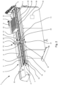
- the magazine 1 is a unit configured to hold and feed carton blanks 2 to a packaging machine 32, illustrated in Fig. 8 .
- the magazine 1 comprises a guide unit 3 extending along an upper part of the magazine 1.
- carton blanks 2 are configured to be arranged.
- the carton blanks 2 may be arranged in a stack of blanks 33 and configured to be placed on the upper surface 4.
- the guide unit 3 comprises a first long side 7 and a second long side 8, which sides are parallel to each other.
- the guide unit 3, with the upper surface 4 has a slight inclination from the second long side 8 and towards the first side 7.
- a guide wall 9 is arranged.
- the magazine 1 comprises a follower 10 which may be arranged along the first long side 7.
- the follower 10 is configured to move, travel, along the length of the guide unit 3.
- the length of the guide unit 3 may be defined as the length which extends between one first end of the guide unit 3 and a feed end 6.
- the follower 10 comprises a drive unit 14 which cooperates with an actuator 15.
- the actuator 15 extends parallel and along the length of the guide unit 3.
- the drive unit 14 comprises a lower portion 25 and an upper portion 26.
- the lower portion 25 is slidable connected to the actuator 15.
- the lower portion 25 may have an enclosed connection around the actuator 15 whereby the drive unit 14 is operable arranged to slide along the actuator 15.
- the drive unit 14 may pivot around the actuator 15.
- the upper portion 26 may slide along a support bar 28 which may provide an extra support of the drive unit 14.
- the support bar 28 is arranged to extend along the guide unit 3.
- the support bar 28 may comprise the guide wall 9.
- a protrusion 29 extending along the guide unit 3 may be arranged.
- the protrusion 29 may be configured to slidably fit or connect into a notch or groove arranged in the upper portion 26 which faces towards the support bar 28.
- the magazine 1 comprises a measuring device 17 for measuring the position of the follower 10 along the length of the guide unit 3.
- the measuring device 17 comprises a sensor device 5.
- the sensor device 5 may be arranged at the one first end of the guide unit 3, opposite the feed end 6.
- the sensor device 5 is configured to generate a signal which signal may be indicative of a distance d1 between the follower 10 and the feed end 6.
- the follower 10 comprises a handle 20.
- the follower 10 is configured to be set in one of a feeding position P1 or a loading position P2.
- Fig. 1 illustrates a situation when the follower 10 is arranged in loading position P2.
- Fig. 2 illustrates a situation when the follower 10 is arranged in a feeding position P1.
- the distance d1 may be defined as the distance, or length, between the position of the follower 10 when arranged in the feeding position P1 and the feed end 6.
- the generated signal from the sensor device 5 is arranged to detect whether the follower 10 is set in the feeding position P1 or the loading position P2.
- the sensor device 5 comprises a light emitter 19.
- the light emitter 19 is configured to generate a beam of light 18.
- the beam of light 18 is arranged to be transmitted from the sensor device 5 in a direction towards the feed end 6.
- the beam of light 18 is configured to have an extension which is parallel with the actuator 15.
- the follower 10 Upon change of the follower 10 from the feeding position P1 to the loading position P2 to, the follower 10 is arranged to interrupt, block, the extension of the beam of light 18 extending along the length of the of the guide unit 3.
- the position along the guide unit 3 where the follower is set in position or arrangement interrupting the extension of the beam light 18 is registered as a signal and communicated to the processing unit 16.
- the follower 10, arranged in feeding position P1, and movable along the guide unit 3, is configured to apply a force on the stack of carton blanks 33 to push the stack towards the feed end 6.
- the drive unit 14, which is connected to the follower 10, is configured to impart a movement to the follower 10 in a direction D towards the feed end 6.
- the carton blanks 2 are picked one by one from the stack of carton blanks 33 and moved into the packaging machine 32, illustrated in figure 8 .
- the carton blanks 2 may be picked from the feed end 6 by sucking technology.
- the follower 10 is arranged to move in a direction being transverse the direction D.
- the follower 10 may be pivotably movable relative to the drive unit 14.
- the follower 10 may be linearly movable relative to the drive unit 14.
- the follower 10 When arranged to move linearly relative to the drive unit 14, the follower 10 may be arranged to move from the side of the guide unit 3 in a direction parallel with the upper surface 4.
- the follower 10 When the follower is in the feeding position P1 respectively in the loading position P2, the follower 10 may be arranged to interact with the sensor device 5 such that the drive unit 14 being arranged with the actuator 15 may be activated respectively deactivated.
- the follower 10 is arranged to pivotably move relative to the guide unit 3 or the drive unit 14 by an angle of at least 70°.
- An angle of at least 70° may allow movement of a stack of carton blanks 33 to be freely moved back and forth on the guide unit 3 without the follower 10 limits the movements. For example, during loading or maintenance of the magazine 1, it may be desirable to move a stack of carton blanks 33 freely back and forth along the guide unit 3 without interference of the follower 10.
- the magazine 1 comprises a processing unit 16.
- the processing unit 16 is operatively connected to the sensor device 5.
- the processing unit 16 is configured to control the drive unit 14 to impart movement of the follower 10 when the follower 10 is in the feeding position P1.
- the processing unit 16 is configured to inactivate the movement of the follower 10.
- the processing unit 16 is operatively connected to the actuator 15.
- the actuator is arranged to determine the movements of the follower 10, which is connected with the drive unit 14, along the extension of the actuator 15.
- the actuator 15 may be pneumatically driven, driven by wire, or by an electrical motor.
- a switch 35 may be operatable connected with the follower 10.
- the switch 35 may be arranged for controlling and regulating the actuator 15.
- the switch 35 may be arranged on the drive unit 14.
- the switch 35 may be arranged to communicate with the processing unit 16.
- the processing unit 16 is configured to obtain information from the sensor device 5.
- the information from the sensor device 5 may be processed in the processing unit 16 whereby the distance d1 between the follower 10 and the feed end 6 may be obtained.
- a value representing the thickness of a carton blank 2 may be preset or manually typed or loaded into the processing unit 16.
- the follower 10 comprises a push surface 12 configured to be brought in contact for pushing against a push side 13 on the stack of carton blanks 33 arranged on the guide unit 3.
- a picking end 21 is configured. From the picking end 21 of the stack of carton blanks 33, one by one a carton blank 2 is arranged to be picked from the stack while the stack is pushed in direction D towards the feed end 6.
- the distance d1 may be defined as distance between the feed end 6 and the position of the follower 10 arranged in the feeding position P1 when the push surface 12 is brought into contact with the push side 13 against the stack of carton blanks 33.
- the processing unit 16 is configured to determine the number of carton blanks 2 arranged on the guide unit 3 when the follower 10 is moved from the loading position P2 to the feeding position P1.
- the processing unit 16 may be configured to obtain information from a counter.
- the counter may be a sensor arranged at the feed end 6.
- the counter is configured to count the number of carton blanks 2 that are picked from the picking end 21 of the stack of carton blanks 33 as the stack is pushed in direction D towards the feed end 6.
- the processing unit 16 may be configured to control the drive unit 14 to adjust the force applied by the follower 10 on the stack of blanks 33, in dependence of the number of blanks that are picked from the feed end 6.
- the processing unit 16 may be configured to receive from the sensor device 5 a signal indicative of the first distance d1 between the follower 10 and the feed end 6 and count the number of carton blanks 2 that are picked from the feed end 6. After the number of carton blanks 2 have been picked from the feed end 6, the processing unit 16 may be configured to receive from the sensor device 5 a signal indicative of a second distance between the follower 10 and the feed end 6, and determine a value representing the thickness of a carton blank 2, which is based on the first and second distance and the numbers of counted carton blanks 2. With information of the first and second distance, which may be stored and used dynamically, the magazine 1 may regularly be calibrated for optimized performance.
- a magazine 1 comprising a stack of carton blanks 33 arranged in position for the carton blanks 2 to be picked one by one from the picking end 21 of the stack is illustrated.
- the follower 10 is arranged in the feeding position P1. Arranged in feeding position P1, the follower 10 may be arranged to be moved into a a contact position with the stack of carton blanks 33 for applying a force against the stack of carton blanks 33. The force applied may push the stack of carton blanks 33 continuously towards the feed end 6 until the follower 10 is arranged into the loading position P2. When the follower 10 is arranged into the loading position, the force applied against the stack will halt.
- the guide unit 3 comprises a lower surface 31, opposite the upper surface 4, and the first and second long side 7, 8. At the one short end, the first end, the sensor device 5 is arranged. At the other short side, the feed end 6 is arranged.
- the actuator 15 extends along the guide unit 3 between the two short ends.
- the lower portion 25 of the drive unit 14 is movable connected to the actuator 15.
- the follower 10 is arranged in the loading position P2. In the loading position P2, the beam of light may not be interrupted, unbroken, whereby the beam of light 18 may extend along the length of the guide unit 3. The extension of the beam of light 18 may extend parallel and slightly below the lower surface 31 of the guide unit 3.
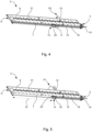
- the guide unit 3 as seen from underneath is illustrated.
- the guide unit 3 comprises the lower surface 31, and the first and second long side 7, 8.
- the sensor device 5 At the one short end, the first end, the sensor device 5 is arranged.
- the feed end 6 At the other short side, the feed end 6 is arranged.
- the actuator 15 extends along the guide unit 3 between the two short ends.
- the lower portion 25 of the drive unit 14 is movable connected to the actuator 15.
- the follower 10 is arranged in feeding position P1.
- the sensor device 5 comprises the light emitter 19.
- the follower 10 is arranged to interrupt the beam of light 18 emitted by the light emitter 19 when the follower 10 is set in the feeding position P1.
- the follower 10 may be arranged to interrupt the beam of light 18 emitted by the light emitter 19 when the follower 10 is set in the loading position P2.
- the follower 10 may comprise a lever element 24.
- the level element 24 is a surface configured to interrupt, break, the extension of the beam of light 18 between the sensor device 5 and the feed end 6.
- the lever element 24 which is part of the follower 10 is arranged to be brough into an intersection position for intersecting, blocking, the extension of the beam of light 18.
- the beam of light 18 from the light emitter 19 extends to a position of the follower arranged in the feeding position P1 which is arranged at a distance from the feed end 6.
- the sensor device 5 is configured to register the distance of the beam of light 18 from the sensor device 5 and to the lever element 5 and communicate the register of the distance as a signal to the processing unit 16.
- the signal may be processed for obtaining the distance d1 between the follower 10 and the feed end 6.
- the sensor device 5 may be arranged at the feed end 6 to measure the distance between follower 10 and the feed end 6.
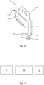
- the follower 10 comprises the handle 20 for allowing an operator to move the follower 10 relative to the guide unit 3. An operator may also move the follower 10 along the guide unit by pushing the handle in either direction along the guide unit 3.
- the handle 20 is arranged with an arm 11 which extends to a pivot area 23.
- the pivot area 23 comprises a pivot point 22.
- the follower 10 may pivot around the pivot point 22.
- To the pivot area 23, the lever element 24 is arranged.
- the lever element 24 is arranged to connect with the arm 11 through the pivot area 23.
- the lever element 24, the arm 11 and the pivot area 23 may be made of one same material.
- the follower 10 comprises a blade comprising a push surface 12 and back surface 30.
- a magazine 1 cooperating with a packaging machine 32 are schematically illustrated.
- the packaging machine 32 is configured to receive carton blanks 2 from the magazine 1, form packages 34 from the carton blanks 2 and fill food product in the packages 34.
- the magazine 1 and the packaging machine 32 are arranged to cooperative such that the feed end 6 communicates with a receiving opening on the packaging machine 32.
- a picking unit for example unit utilizing sucking technology, is arranged to pick carton blanks 2 one by one from the feed end 6. From the feed end 6, respective carton blank 2 may be moved into the packaging machine 32.
- the carton blanks 2 are formed from a flat shaped carton to a package 34 arranged to be filled with the food product.
- the packages 34 have been filled with the food product, from the packaging machine they are transported for delivery for further handling, for example to a storage facility or consumer.
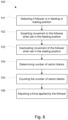
- the method 100 comprises a first step 101 for detecting whether the follower 10 is set in the feeding position P1 or in the loading position P2. Thereafter, in a second step 102, imparting movement to the follower 10 when the follower 10 is set in the feeding position P1. In a third step 103, inactivating said movement of the follower 10 when the follower 10 is set in the loading position P2. Thereafter, in a fourth step 104, determining the number of carton blanks 2 in the guide unit 3 when the follower is moved from the loading position P2 to the feeding position P1.
- the determination of the number of carton blanks 2 in this fourth step 104 is based on the distance d1 between the follower 10 and the feed end 6, and a value representing the thickness of a carton blank 2.
- a fifth step 105 counting the number of carton blanks 2 that are picked from the feed end 6.
- a sixth step 106 adjusting the force applied by the follower 10 on the stack of carton blanks 33, in dependence of the number of carton blanks that are picked from the feed end 6.
Landscapes
- Engineering & Computer Science (AREA)
- Mechanical Engineering (AREA)
- Supplying Of Containers To The Packaging Station (AREA)
- Sheets, Magazines, And Separation Thereof (AREA)
Abstract

Description
- The invention relates to a magazine for feeding carton blanks to a packaging machine. The packaging machine is arranged to receive the carton blanks from the magazine, form packages from the carton blanks, and fill food product in packages.
- In the food packaging industry, the utilization of packaging machines to convert carton blanks into packaging containers is a widespread practice. These packaging machines require carton blank magazines that consistently and precisely supply carton blanks to ensure optimal operational efficiency. Nonetheless, conventional blank magazines, also referred to as blank feeding mechanisms, despite their historical use, exhibit limitations concerning their speed, precision, and reliability, potentially causing inefficiencies in production and operational downtimes.
- Conventional blank magazines frequently rely on either gravity-fed or mechanical blank-pushing devices for their functionality. In such devices, the weight of the stack of carton blanks, alternatively a pushing force, is exploited to drive the blanks towards the feed end of the magazine. Although these blank magazines have proven to successfully supply carton blanks to packaging machines, they are not without their challenges. Uneven feeding, misalignment of carton blanks, and frequent stoppages resulting from carton jams may be encountered when using these blank magazines. Also, an inherent lack of precise control over the force applied to the stack of carton blanks can lead to detrimental effects on the feeding process and consequently the operation of the packaging machine.
- Reference can be made to patent document
DE102013101808B4 , which falls within the purview of the prior art and exemplifies some of the existing techniques for feeding carton blanks to a packaging machine. While this document presents a magazine capable of effectively feeding carton blanks, it underscores the need for more robust techniques to accurately determine and control the feed pressure exerted on the blanks. For instance, the sensor used for adapting the pressure by which the carton blanks are fed to the packaging machine appears to be sensitive to disturbances. - Thus, there exists a need for innovative solutions that can address the shortcomings of, or at least improve, the operation of conventional blank magazines. For example, at least one of the limitations related to speed, precision, reliability, reloading of blanks in the blank magazines, and controlled force application on the blanks, should be effectively tackled to achieve improved production efficiency and reduced operational downtimes in the food packaging industry.
- It is an object of the invention to at least partly overcome one or more of the above-identified limitations of the prior art. One such object is to provide for reliably feeding blanks to a packaging machine, while still ensuring efficient operation of the magazine, including convenient filling of blanks in the magazine.
- One or more of these objectives, as well as further objectives that may appear from the aspects and the description below, are at least partly achieved by a magazine for feeding carton blanks, a packaging machine and a method according to the independent claims, embodiments thereof being defined by the dependent claims.
- A first aspect relates to a magazine for feeding carton blanks to a packaging machine. The magazine comprises a guide unit arranged to hold a stack of carton blanks; a feed end located at an end of the guide unit, for allowing carton blanks to be picked from the magazine at the feed end; a follower that is movable along the guide unit, for allowing carton blanks to be pushed towards the feed end when the stack of carton blanks is positioned between the feed end and the follower; a drive unit to which the follower is connected, the drive unit being controllable to impart a movement to the follower in a direction towards the feed end, such that the follower applies a force on the stack of carton blanks; and a sensor device arranged to generate a signal indicative of the distance between the follower and the feed. The follower is arranged to be set in one of a feeding position and a loading position, and the sensor device is arranged to generate a signal for detecting whether the follower is set in the feeding position or the loading position. The magazine further comprises a processing unit operatively connected to the sensor device, and configured to control the drive unit to impart said movement to the follower when the follower is in the feeding position, and inactivate said movement of the follower when the follower is in the loading position.
- As used herein, the term "sensor device" refers to one or more sensor, which may include a processing unit, such as a microcontroller, for converting a signal generated by the sensor device to a value or signal format that represents the value or measurement the sensor has measured (sensed).
- As used herein, the feeding position respectively the loading position refers to operational positions, also referred to as operational settings, of the follower.
- In further detail, the processing unit operatively connected to the sensor device for receiving the signals from the sensor unit. The processing unit can therefore, for example, perform calculations and control various operations that use the setting of the follower as input.
- The magazine is advantageous in that it provides a secure way for determining when carton blanks shall be pushed towards the feed end. This provides, in turn, for convenient reloading of new blanks into the magazine. Moreover, the magazine also offers a convenient possibility to implement adjustment of the pressure by which the carton blanks shall be pushed with towards the feed end.
- In some embodiments, the follower is pivotably and/or linearly movable relative to the guide unit, between the feeding position and the loading position. This facilitates cooperation between the follower, the sensor device and the processing unit. The follower may be pivotably and/or linearly movable as seen in relation to the guide unit. The pivoting movement may be a pivoting movement about the longitudinal axis of the guide unit. The linear movement may be a movement, or may comprise a linear movement component, that is transverse the longitudinal axis of the guide unit.
- In some embodiments, the follower is pivotably and/or linearly movable relative to the drive unit, between the feeding position and the loading position. This has the positive effect that the drive unit may arranged to move along the guide unit while the follower may move relative the drive unit. One effect of this is that it will reduce the risk that the drive unit is rapidly worn out in regards of its ability to move along the guide unit.
- In some embodiments, the follower is pivotably movable by an angle of least 70°. Tests have shown that such angle allows for convenient loading of blanks in the magazine. In some embodiments, the follower comprises a handle for allowing an operator to move the follower relative to the guide unit. In some embodiments, the follower is arranged to interact with the sensor device such that the drive unit is activated respectively deactivated when the follower is in the feeding position respectively in the loading position. This has the effect the follower may act as switch in regarding of the operation of the magazine as the follower may be brought into either a feeding position or loading position.
- In some embodiments, the sensor device comprises a light emitter, and the follower is arranged to interrupt a beam of light emitted by the light emitter when the follower is set in either the feeding position or in the loading position.
- In some embodiments, the drive unit comprises an actuator for imparting respectively inactivating said movement to the follower, and a switch that is operably connected to the follower and arranged to control the actuator.
- In some embodiments, the processing unit is configured to determine the number of carton blanks in the guide unit when the follower is moved from the loading position to the feeding position, based on the distance between the follower and the feed end, and a value representing the thickness of a carton blank.
- In some embodiments, the processing unit is configured to count the number of blanks that are picked from the feed end, and control the drive unit to adjust the force applied by the follower on the stack of carton blanks, in dependence of the number of blanks that are picked from the feed end.
- In some embodiments, the processing unit is configured to receive from the sensor device a signal indicative of a first distance between the follower and the feed end; count the number of blanks that are picked from the feed end; receive from the sensor device a signal indicative of a second distance between the follower and the feed end, after the number of blanks have been picked from the feed end; and determine a value representing the thickness of a carton blank, based on the first and second distances and the numbers of counted blanks. Such determined value representing the thickness may be used in subsequent operation of the magazine, where the value can be used for calculating the number of blanks in the magazine, and adjusting the force applied by the follower on the stack of carton blanks accordingly.
- A second aspect relates to a packaging machine that comprising a magazine according to the first aspect, including any embodiments thereof. The packaging machine is arranged to receive the carton blanks from the magazine, form packages from the carton blanks, and fill food product in packages.
- A third aspect relates to a method performed by a magazine according to the first aspect, including any embodiments thereof. The method comprises: detecting whether the follower is set in the feeding position or the loading position; imparting movement to the follower when the follower is set in the feeding position; and inactivating said movement of the follower when the follower is set in the loading position.
- In some embodiments, the method comprises determining the number of carton blanks in in the guide unit, when the follower is moved from the loading position to the feeding position, based on the distance between the follower and the feed end, and a value representing the thickness of a carton blank.
- In some embodiments, the method comprises counting the number of blanks that are picked from the feed end, and adjusting the force applied by the follower on the stack of carton blanks, in dependence of the number of blanks that are picked from the feed end.
- The packaging machine and the method according to the second and third aspects, including embodiments thereof, have the same advantages as the magazine.
- Still other objectives, features, embodiments, and aspects, as well as additional features and advantages will appear from the following detailed description as well as from the accompanying schematic drawings.
-
-
Fig. 1 is a perspective view of a magazine that is set in a loading position. -
Fig. 2 is a perspective view of a magazine that is set in a feeding position. -
Fig. 3 is a perspective view of a magazine that is set in a feeding position, with a stack of carton blanks located near a feed end of the magazine. -
Fig. 4 is a perspective view of a guide unit of a magazine, as seen from underneath when the magazine is set in a loading position. -
Fig. 5 is a perspective view of a guide unit of a magazine, as seen from underneath when the magazine is set in a feeding position. -
Fig. 6 is a perspective view of a follower of a magazine. -
Fig. 7 is a schematic view of a magazine and a packing machine for producing packages. -
Fig. 8 is a schematic view of a flow chart illustrating a method performed by the magazine. - Embodiments will now be described more fully hereinafter with reference to the accompanying drawings, in which some, but not all, embodiments are shown. Indeed, the subject of the present disclosure may be embodied in many different forms and should not be construed as limited to the embodiments set forth herein; rather, these embodiments are provided so that this disclosure may satisfy applicable legal requirements.
- Where possible, any of the advantages, features, functions, devices, and/or operational aspects of any of the embodiments described and/or contemplated herein may be included in any of the other embodiments described and/or contemplated herein, and/or vice versa. In addition, where possible, any terms expressed in the singular form herein are meant to also include the plural form and/or vice versa, unless explicitly stated otherwise. Accordingly, the terms "a" and/or "an" shall mean "at least one" or "one or more", even though the phrase "one or more" or "at least one" is also used herein. The terms "multiple", "plural" and "plurality" are intended to imply provision of two or more elements. The term "and/or" includes any and all combinations of one or more of the associated listed elements. Although the terms first, second, etc. may be used herein to describe various elements, these elements should not be limited by these terms. These terms are only used to distinguish one element from another. For example, a first element could be termed a second element, and, similarly, a second element could be termed a first element, without departing the scope of the present disclosure.
- Well-known functions or constructions may not be described in detail for brevity and/or clarity. Unless otherwise defined, all terms (including technical and scientific terms) used herein have the same meaning as commonly understood by one of ordinary skill in the art to which this disclosure belongs.
- Like reference signs refer to like elements throughout.
- With reference to
Fig. 1 andFig. 2 , amagazine 1 is illustrated. Themagazine 1 is a unit configured to hold and feedcarton blanks 2 to apackaging machine 32, illustrated inFig. 8 . Themagazine 1 comprises aguide unit 3 extending along an upper part of themagazine 1. Against anupper surface 4 of theguide unit 3carton blanks 2 are configured to be arranged. Thecarton blanks 2 may be arranged in a stack ofblanks 33 and configured to be placed on theupper surface 4. Theguide unit 3 comprises a firstlong side 7 and a secondlong side 8, which sides are parallel to each other. Theguide unit 3, with theupper surface 4, has a slight inclination from the secondlong side 8 and towards thefirst side 7. Along the first side 7 aguide wall 9 is arranged. Because of the inclination of theupper surface 4, the stack ofcarton blanks 33, when placed on theguide unit 3, may slide and position it towards theguide wall 9. Theguide wall 9 is configured to support the stack ofblanks 33 whereby thecarton blanks 2 are arranged one after each other and in line for movement along theguide unit 3. Themagazine 1 comprises afollower 10 which may be arranged along the firstlong side 7. Thefollower 10 is configured to move, travel, along the length of theguide unit 3. The length of theguide unit 3 may be defined as the length which extends between one first end of theguide unit 3 and afeed end 6. Thefollower 10 comprises adrive unit 14 which cooperates with anactuator 15. Theactuator 15 extends parallel and along the length of theguide unit 3. Thedrive unit 14 comprises alower portion 25 and anupper portion 26. Thelower portion 25 is slidable connected to theactuator 15. Thelower portion 25 may have an enclosed connection around theactuator 15 whereby thedrive unit 14 is operable arranged to slide along theactuator 15. Optionally, thedrive unit 14 may pivot around theactuator 15. Theupper portion 26 may slide along asupport bar 28 which may provide an extra support of thedrive unit 14. Thesupport bar 28 is arranged to extend along theguide unit 3. Thesupport bar 28 may comprise theguide wall 9. Along thesupport bar 28, faced away from theguide unit 3, aprotrusion 29 extending along theguide unit 3 may be arranged. Theprotrusion 29 may be configured to slidably fit or connect into a notch or groove arranged in theupper portion 26 which faces towards thesupport bar 28. - The
magazine 1 comprises a measuringdevice 17 for measuring the position of thefollower 10 along the length of theguide unit 3. The measuringdevice 17 comprises asensor device 5. Thesensor device 5 may be arranged at the one first end of theguide unit 3, opposite thefeed end 6. Thesensor device 5 is configured to generate a signal which signal may be indicative of a distance d1 between thefollower 10 and thefeed end 6. Thefollower 10 comprises ahandle 20. Thefollower 10 is configured to be set in one of a feeding position P1 or a loading position P2.Fig. 1 illustrates a situation when thefollower 10 is arranged in loading position P2.Fig. 2 illustrates a situation when thefollower 10 is arranged in a feeding position P1. An operator may move thefollower 10 by gripping thehandle 5 and move thefollower 10 into the desired position, either along theguide unit 3 or into a feeding position P1 or a loading position P2. The distance d1 may be defined as the distance, or length, between the position of thefollower 10 when arranged in the feeding position P1 and thefeed end 6. The generated signal from thesensor device 5 is arranged to detect whether thefollower 10 is set in the feeding position P1 or the loading position P2. Thesensor device 5 comprises alight emitter 19. Thelight emitter 19 is configured to generate a beam oflight 18. The beam oflight 18 is arranged to be transmitted from thesensor device 5 in a direction towards thefeed end 6. The beam oflight 18 is configured to have an extension which is parallel with theactuator 15. Upon change of thefollower 10 from the feeding position P1 to the loading position P2 to, thefollower 10 is arranged to interrupt, block, the extension of the beam of light 18 extending along the length of the of theguide unit 3. The position along theguide unit 3 where the follower is set in position or arrangement interrupting the extension of thebeam light 18 is registered as a signal and communicated to theprocessing unit 16. - The
follower 10, arranged in feeding position P1, and movable along theguide unit 3, is configured to apply a force on the stack ofcarton blanks 33 to push the stack towards thefeed end 6. Thedrive unit 14, which is connected to thefollower 10, is configured to impart a movement to thefollower 10 in a direction D towards thefeed end 6. At thefeed end 6, thecarton blanks 2 are picked one by one from the stack ofcarton blanks 33 and moved into thepackaging machine 32, illustrated infigure 8 . Thecarton blanks 2 may be picked from thefeed end 6 by sucking technology. Changing between the loading position P2 and the feeding position P1, thefollower 10 is arranged to move in a direction being transverse the direction D. Thefollower 10 may be pivotably movable relative to thedrive unit 14. Optionally, thefollower 10 may be linearly movable relative to thedrive unit 14. When arranged to move linearly relative to thedrive unit 14, thefollower 10 may be arranged to move from the side of theguide unit 3 in a direction parallel with theupper surface 4. When the follower is in the feeding position P1 respectively in the loading position P2, thefollower 10 may be arranged to interact with thesensor device 5 such that thedrive unit 14 being arranged with theactuator 15 may be activated respectively deactivated. On theupper portion 26 on thedrive unit 14, aslot 27 is arranged. Theslot 27 is configured to cooperate with anarm 11 of thefollower 10, whicharm 11 may be configured to be movably arranged in theslot 27. Thefollower 10 is arranged to pivotably move relative to theguide unit 3 or thedrive unit 14 by an angle of at least 70°. An angle of at least 70° may allow movement of a stack ofcarton blanks 33 to be freely moved back and forth on theguide unit 3 without thefollower 10 limits the movements. For example, during loading or maintenance of themagazine 1, it may be desirable to move a stack ofcarton blanks 33 freely back and forth along theguide unit 3 without interference of thefollower 10. - The
magazine 1 comprises aprocessing unit 16. Theprocessing unit 16 is operatively connected to thesensor device 5. Theprocessing unit 16 is configured to control thedrive unit 14 to impart movement of thefollower 10 when thefollower 10 is in the feeding position P1. When thefollower 10 is in loading position P2, theprocessing unit 16 is configured to inactivate the movement of thefollower 10. Theprocessing unit 16 is operatively connected to theactuator 15. The actuator is arranged to determine the movements of thefollower 10, which is connected with thedrive unit 14, along the extension of theactuator 15. Theactuator 15 may be pneumatically driven, driven by wire, or by an electrical motor. Aswitch 35 may be operatable connected with thefollower 10. Theswitch 35 may be arranged for controlling and regulating theactuator 15. Optionally, theswitch 35 may be arranged on thedrive unit 14. Theswitch 35 may be arranged to communicate with theprocessing unit 16. - The
processing unit 16 is configured to obtain information from thesensor device 5. The information from thesensor device 5 may be processed in theprocessing unit 16 whereby the distance d1 between thefollower 10 and thefeed end 6 may be obtained. A value representing the thickness of acarton blank 2 may be preset or manually typed or loaded into theprocessing unit 16. Thefollower 10 comprises apush surface 12 configured to be brought in contact for pushing against apush side 13 on the stack ofcarton blanks 33 arranged on theguide unit 3. On the other side of the stack ofcarton blanks 33, towards thefeed end 6, a pickingend 21 is configured. From the pickingend 21 of the stack ofcarton blanks 33, one by one acarton blank 2 is arranged to be picked from the stack while the stack is pushed in direction D towards thefeed end 6. The distance d1 may be defined as distance between thefeed end 6 and the position of thefollower 10 arranged in the feeding position P1 when thepush surface 12 is brought into contact with thepush side 13 against the stack ofcarton blanks 33. With information about the distance d1 and the thickness of acarton blank 2, theprocessing unit 16 is configured to determine the number ofcarton blanks 2 arranged on theguide unit 3 when thefollower 10 is moved from the loading position P2 to the feeding position P1. - The
processing unit 16 may be configured to obtain information from a counter. The counter may be a sensor arranged at thefeed end 6. The counter is configured to count the number ofcarton blanks 2 that are picked from the pickingend 21 of the stack ofcarton blanks 33 as the stack is pushed in direction D towards thefeed end 6. - The
processing unit 16 may be configured to control thedrive unit 14 to adjust the force applied by thefollower 10 on the stack ofblanks 33, in dependence of the number of blanks that are picked from thefeed end 6. - The
processing unit 16 may be configured to receive from the sensor device 5 a signal indicative of the first distance d1 between thefollower 10 and thefeed end 6 and count the number ofcarton blanks 2 that are picked from thefeed end 6. After the number ofcarton blanks 2 have been picked from thefeed end 6, theprocessing unit 16 may be configured to receive from the sensor device 5 a signal indicative of a second distance between thefollower 10 and thefeed end 6, and determine a value representing the thickness of acarton blank 2, which is based on the first and second distance and the numbers of countedcarton blanks 2. With information of the first and second distance, which may be stored and used dynamically, themagazine 1 may regularly be calibrated for optimized performance. - With reference to
Fig. 3 , amagazine 1 comprising a stack ofcarton blanks 33 arranged in position for thecarton blanks 2 to be picked one by one from the pickingend 21 of the stack is illustrated. Thefollower 10 is arranged in the feeding position P1. Arranged in feeding position P1, thefollower 10 may be arranged to be moved into a a contact position with the stack ofcarton blanks 33 for applying a force against the stack ofcarton blanks 33. The force applied may push the stack ofcarton blanks 33 continuously towards thefeed end 6 until thefollower 10 is arranged into the loading position P2. When thefollower 10 is arranged into the loading position, the force applied against the stack will halt. - With reference to
Fig. 4 aguide unit 3 as seen from underneath is illustrated. Theguide unit 3 comprises alower surface 31, opposite theupper surface 4, and the first and secondlong side sensor device 5 is arranged. At the other short side, thefeed end 6 is arranged. Theactuator 15 extends along theguide unit 3 between the two short ends. Thelower portion 25 of thedrive unit 14 is movable connected to theactuator 15. Thefollower 10 is arranged in the loading position P2. In the loading position P2, the beam of light may not be interrupted, unbroken, whereby the beam oflight 18 may extend along the length of theguide unit 3. The extension of the beam oflight 18 may extend parallel and slightly below thelower surface 31 of theguide unit 3. - With reference to
Fig. 5 , aguide unit 3 as seen from underneath is illustrated. Theguide unit 3 comprises thelower surface 31, and the first and secondlong side sensor device 5 is arranged. At the other short side, thefeed end 6 is arranged. Theactuator 15 extends along theguide unit 3 between the two short ends. Thelower portion 25 of thedrive unit 14 is movable connected to theactuator 15. Thefollower 10 is arranged in feeding position P1. Thesensor device 5 comprises thelight emitter 19. Thefollower 10 is arranged to interrupt the beam of light 18 emitted by thelight emitter 19 when thefollower 10 is set in the feeding position P1. Optionally, thefollower 10 may be arranged to interrupt the beam of light 18 emitted by thelight emitter 19 when thefollower 10 is set in the loading position P2. Thefollower 10 may comprise alever element 24. Thelevel element 24 is a surface configured to interrupt, break, the extension of the beam of light 18 between thesensor device 5 and thefeed end 6. When thefollower 10 is arranged in the feeding position P1, thelever element 24 which is part of thefollower 10 is arranged to be brough into an intersection position for intersecting, blocking, the extension of the beam oflight 18. In the feeding position P1, the beam of light 18 from thelight emitter 19 extends to a position of the follower arranged in the feeding position P1 which is arranged at a distance from thefeed end 6. Thesensor device 5 is configured to register the distance of the beam of light 18 from thesensor device 5 and to thelever element 5 and communicate the register of the distance as a signal to theprocessing unit 16. At theprocessing unit 16, the signal may be processed for obtaining the distance d1 between thefollower 10 and thefeed end 6. Optionally, thesensor device 5 may be arranged at thefeed end 6 to measure the distance betweenfollower 10 and thefeed end 6. - With reference to
Fig. 6 , afollower 10 is illustrated. Thefollower 10 comprises thehandle 20 for allowing an operator to move thefollower 10 relative to theguide unit 3. An operator may also move thefollower 10 along the guide unit by pushing the handle in either direction along theguide unit 3. Thehandle 20 is arranged with anarm 11 which extends to apivot area 23. Thepivot area 23 comprises apivot point 22. During operation, thefollower 10 may pivot around thepivot point 22. To thepivot area 23, thelever element 24 is arranged. Thelever element 24 is arranged to connect with thearm 11 through thepivot area 23. Thelever element 24, thearm 11 and thepivot area 23 may be made of one same material. Thefollower 10 comprises a blade comprising apush surface 12 and backsurface 30. - With reference to
Fig. 7 , amagazine 1 cooperating with apackaging machine 32 are schematically illustrated. Thepackaging machine 32 is configured to receivecarton blanks 2 from themagazine 1, form packages 34 from thecarton blanks 2 and fill food product in thepackages 34. Themagazine 1 and thepackaging machine 32 are arranged to cooperative such that thefeed end 6 communicates with a receiving opening on thepackaging machine 32. A picking unit, for example unit utilizing sucking technology, is arranged to pickcarton blanks 2 one by one from thefeed end 6. From thefeed end 6, respective carton blank 2 may be moved into thepackaging machine 32. In thepackaging machine 32, thecarton blanks 2 are formed from a flat shaped carton to apackage 34 arranged to be filled with the food product. When thepackages 34 have been filled with the food product, from the packaging machine they are transported for delivery for further handling, for example to a storage facility or consumer. - With reference to
Fig. 8 , a flowchart of amethod 100 comprising amagazine 1 is illustrated. Themethod 100 comprises afirst step 101 for detecting whether thefollower 10 is set in the feeding position P1 or in the loading position P2. Thereafter, in asecond step 102, imparting movement to thefollower 10 when thefollower 10 is set in the feeding position P1. In athird step 103, inactivating said movement of thefollower 10 when thefollower 10 is set in the loading position P2. Thereafter, in afourth step 104, determining the number ofcarton blanks 2 in theguide unit 3 when the follower is moved from the loading position P2 to the feeding position P1. The determination of the number ofcarton blanks 2 in thisfourth step 104 is based on the distance d1 between thefollower 10 and thefeed end 6, and a value representing the thickness of acarton blank 2. Thereafter, in afifth step 105, counting the number ofcarton blanks 2 that are picked from thefeed end 6. In asixth step 106, adjusting the force applied by thefollower 10 on the stack ofcarton blanks 33, in dependence of the number of carton blanks that are picked from thefeed end 6. - From the description above follows that, although various embodiments of the invention have been described and shown, the invention is not restricted thereto, but may also be embodied in other ways within the scope of the subject-matter defined in the following claims.
Claims (15)
- A magazine (1) for feeding carton blanks (2) to a packaging machine (32), the magazine (1) comprising:a guide unit (3) arranged to hold a stack of carton blanks (33),a feed end (6) located at an end of the guide unit (3), for allowing carton blanks (2) to be picked from the magazine (1) at the feed end (6),a follower (10) that is movable along the guide unit (3), for allowing carton blanks (2) to be pushed towards the feed end (6) when the stack of carton blanks (33) is positioned between the feed end (6) and the follower (10),a drive unit (14) to which the follower (10) is connected, the drive unit (14) being controllable to impart a movement to the follower (10) in a direction (D) towards the feed end (6), such that the follower (10) applies a force on the stack of carton blanks (33),a sensor device (5) arranged to generate a signal indicative of the distance (d1) between the follower (10) and the feed end (6), whereinthe follower (10) is arranged to be set in one of a feeding position (P1) and a loading position (P2),the sensor device (5) is arranged to generate a signal for detecting whether the follower (10) is set in the feeding position (P1) or the loading position (P2), andthe magazine (1) comprises a processing unit (16) operatively connected to the sensor device (5), and configured to control the drive unit (14) to impart said movement to the follower (10) when the follower (10) is in the feeding position (P1), and inactivate said movement of the follower (10) when the follower (10) is in the loading position (P2).
- A magazine (1) according to claim 1, wherein the follower (10) is pivotably and/or linearly movable relative to the guide unit (3), between the feeding position (P1) and the loading position (P2).
- A magazine (1) according to any preceding claim, wherein the follower (10) is pivotably and/or linearly movable relative to the drive unit (14), between the feeding position (P1) and the loading position (P2).
- A magazine (1) according to claim 2 or 3, wherein the follower (10) is pivotably movable by an angle of least 70°.
- A magazine (1) according to any preceding claim, wherein the follower (10) comprises a handle (20) for allowing an operator to move the follower (10) relative to the guide unit (3).
- A magazine (1) according to any preceding claim, wherein the follower (10) is arranged to interact with the sensor device (5) such that the drive unit (14) is activated respectively deactivated when the follower is in the feeding position (P1) respectively in the loading position (P2).
- A magazine (1) according to any preceding claim, whereinthe sensor device (5) comprises a light emitter (19), andthe follower (10) is arranged to interrupt a beam of light (18) emitted by the light emitter (19) when the follower (10) is set in either the feeding position (P1) or in the loading position (P2).
- A magazine (1) according to any preceding claim, whereinthe drive unit (14) comprises an actuator (15) for imparting respectively inactivating said movement to the follower (10), anda switch 35that is operably connected to the follower (10) and arranged to control the actuator (15).
- A magazine (1) according to any preceding claim, wherein the processing unit (16) is configured to determine the number of carton blanks in the guide unit (3) when the follower (10) is moved from the loading position (P2) to the feeding position (P1), based onthe distance (d1) between the follower (10) and the feed end (6), anda value representing the thickness of a carton blank.
- A magazine (1) according to claim 9, wherein the processing unit (16) is configured tocount the number of blanks (2) that are picked from the feed end (6), andcontrol the drive unit (14) to adjust the force applied by the follower (10) on the stack of carton blanks (33), in dependence of the number of blanks that are picked from the feed end (6).
- A magazine (1) according to any preceding claim, wherein the processing unit (16) is configured toreceive from the sensor device (5) a signal indicative of a first distance (d1) between the follower (10) and the feed end (6),count the number of blanks that are picked from the feed end (6),receive from the sensor device (5) a signal indicative of a second distance between the follower (10) and the feed end (6), after the number of blanks have been picked from the feed end (6), anddetermine a value representing the thickness of a carton blank, based on the first and second distances and the numbers of counted blanks.
- A packaging machine (32) comprising a magazine (1) according to any preceding claim,
the packaging machine (32) being arranged to receive the carton blanks (2) from the magazine (1), form packages (34) from the carton blanks (2), and fill food product in packages (34). - A method (100) performed by a magazine (1) according to any one of claim 1 - 11, the method (100) comprising:detecting (101) whether the follower (10) is set in the feeding position (P1) or the loading position (P2),imparting movement (102) to the follower (10) when the follower (10) is set in the feeding position (P1), andinactivating (103) said movement of the follower (10) when the follower (10) is set in the loading position (P2).
- A method (100) according to claim 13, comprisingdetermining (104) the number of carton blanks in the guide unit (3), when the follower (10) is moved from the loading position (P2) to the feeding position (P1), based onthe distance (d1) between the follower (10) and the feed end (6), anda value representing the thickness of a carton blank (2).
- A method (100) according to claim 14, comprisingcounting (105) the number of carton blanks (2) that are picked from the feed end (6), andadjusting (106) the force applied by the follower (10) on the stack of carton blanks (33), in dependence of the number of carton blanks (2) that are picked from the feed end (6).
Applications Claiming Priority (1)
| Application Number | Priority Date | Filing Date | Title |
|---|---|---|---|
| EP23195177 | 2023-09-04 |
Publications (1)
| Publication Number | Publication Date |
|---|---|
| EP4516708A1 true EP4516708A1 (en) | 2025-03-05 |
Family
ID=87930330
Family Applications (1)
| Application Number | Title | Priority Date | Filing Date |
|---|---|---|---|
| EP24186707.6A Pending EP4516708A1 (en) | 2023-09-04 | 2024-07-05 | Magazine and corresponding method for feeding carton blanks to a packaging machine |
Country Status (3)
| Country | Link |
|---|---|
| EP (1) | EP4516708A1 (en) |
| CN (1) | CN121794205A (en) |
| WO (1) | WO2025051415A1 (en) |
Citations (8)
| Publication number | Priority date | Publication date | Assignee | Title |
|---|---|---|---|---|
| JPS5147767U (en) * | 1974-09-10 | 1976-04-09 | ||
| US4302000A (en) * | 1978-11-29 | 1981-11-24 | Licentia Patent-Verwaltungs-G.M.B.H. | Apparatus for separating a letter stack |
| WO1988001543A1 (en) * | 1986-09-05 | 1988-03-10 | Opex Corporation | Apparatus for the automated processing of bulk mail and the like |
| EP0696482A2 (en) * | 1994-08-12 | 1996-02-14 | FINMECCANICA S.p.A. | Mail sorting device |
| US6354587B1 (en) * | 2000-05-24 | 2002-03-12 | Lockheed Corp | Follower mechanism for flat article handling system |
| EP1462401A1 (en) * | 2003-03-28 | 2004-09-29 | Mathias Bäuerle GmbH | Apparatus for feeding a sheet of paper, plastic or the like from a stack |
| DE102013101808B4 (en) | 2013-02-25 | 2016-10-13 | Elopak Systems Ag | Magazine for a filling machine and method for feeding packaging coats |
| EP4039625A1 (en) * | 2021-01-22 | 2022-08-10 | ISHIDA CO., Ltd. | Supply apparatus |
-
2024
- 2024-07-05 CN CN202480056623.2A patent/CN121794205A/en active Pending
- 2024-07-05 EP EP24186707.6A patent/EP4516708A1/en active Pending
- 2024-07-05 WO PCT/EP2024/068984 patent/WO2025051415A1/en active Pending
Patent Citations (8)
| Publication number | Priority date | Publication date | Assignee | Title |
|---|---|---|---|---|
| JPS5147767U (en) * | 1974-09-10 | 1976-04-09 | ||
| US4302000A (en) * | 1978-11-29 | 1981-11-24 | Licentia Patent-Verwaltungs-G.M.B.H. | Apparatus for separating a letter stack |
| WO1988001543A1 (en) * | 1986-09-05 | 1988-03-10 | Opex Corporation | Apparatus for the automated processing of bulk mail and the like |
| EP0696482A2 (en) * | 1994-08-12 | 1996-02-14 | FINMECCANICA S.p.A. | Mail sorting device |
| US6354587B1 (en) * | 2000-05-24 | 2002-03-12 | Lockheed Corp | Follower mechanism for flat article handling system |
| EP1462401A1 (en) * | 2003-03-28 | 2004-09-29 | Mathias Bäuerle GmbH | Apparatus for feeding a sheet of paper, plastic or the like from a stack |
| DE102013101808B4 (en) | 2013-02-25 | 2016-10-13 | Elopak Systems Ag | Magazine for a filling machine and method for feeding packaging coats |
| EP4039625A1 (en) * | 2021-01-22 | 2022-08-10 | ISHIDA CO., Ltd. | Supply apparatus |
Also Published As
| Publication number | Publication date |
|---|---|
| WO2025051415A1 (en) | 2025-03-13 |
| CN121794205A (en) | 2026-04-03 |
Similar Documents
| Publication | Publication Date | Title |
|---|---|---|
| EP2548825B1 (en) | Method and system to feed inserts with a rotary and independent gripper system | |
| JP2790193B2 (en) | Material supply device and forging machine | |
| NO167194B (en) | DEVICE FOR SEPARATION OF NUMBER OF LEAVES E.L. FROM A STACK OF LEAVES E.L. | |
| EP3464138B1 (en) | A register, a processing machine and a method for placing plate-like elements | |
| CA1253831A (en) | Method and device for controlling the filling of containers | |
| WO2025051415A1 (en) | Magazine and corresponding method for feeding carton blanks to a packaging machine | |
| US6866262B2 (en) | Positioning device for a gripper carriage of a sheet-processing punching and embossing machine | |
| EP0764132B1 (en) | Force sensing assembly and method for a product delivery system | |
| JP3964410B2 (en) | Feeder with automatic size recognition function | |
| CN201052848Y (en) | Automatic dividing and cutting machine for cascading packing small bag | |
| EP3464141B1 (en) | Detection system for detecting double sheets in a sheet element processing machine, and sheet element processing machine | |
| JPH0738046U (en) | Device for correcting lateral position of plate | |
| KR20150076907A (en) | Paper board stacking device | |
| US3451521A (en) | Apparatus for transferring stacks of sheet material including folded paper handkerchiefs and the like | |
| CN108891982B (en) | Automatic label inserting device | |
| CN223701887U (en) | Cardboard transport equipment | |
| US6505826B2 (en) | Device for separating sheets piled up so as to form a stack, in a feeder of a sheet-processing machine | |
| EP4538208A1 (en) | Feeder with double drive | |
| CN223735579U (en) | Unattached corner blank box transport and shaping device | |
| KR20250026337A (en) | Alignment module with automatic pressure control | |
| JP3807902B2 (en) | Bar material feeder |
Legal Events
| Date | Code | Title | Description |
|---|---|---|---|
| PUAI | Public reference made under article 153(3) epc to a published international application that has entered the european phase |
Free format text: ORIGINAL CODE: 0009012 |
|
| STAA | Information on the status of an ep patent application or granted ep patent |
Free format text: STATUS: THE APPLICATION HAS BEEN PUBLISHED |
|
| AK | Designated contracting states |
Kind code of ref document: A1 Designated state(s): AL AT BE BG CH CY CZ DE DK EE ES FI FR GB GR HR HU IE IS IT LI LT LU LV MC ME MK MT NL NO PL PT RO RS SE SI SK SM TR |
|
| STAA | Information on the status of an ep patent application or granted ep patent |
Free format text: STATUS: REQUEST FOR EXAMINATION WAS MADE |
|
| 17P | Request for examination filed |
Effective date: 20250905 |
|
| STAA | Information on the status of an ep patent application or granted ep patent |
Free format text: STATUS: EXAMINATION IS IN PROGRESS |
|
| 17Q | First examination report despatched |
Effective date: 20260325 |