EP4516666A1 - An aircraft fuselage - Google Patents
An aircraft fuselage Download PDFInfo
- Publication number
- EP4516666A1 EP4516666A1 EP24194768.8A EP24194768A EP4516666A1 EP 4516666 A1 EP4516666 A1 EP 4516666A1 EP 24194768 A EP24194768 A EP 24194768A EP 4516666 A1 EP4516666 A1 EP 4516666A1
- Authority
- EP
- European Patent Office
- Prior art keywords
- roller
- door
- barrier wall
- ramp
- aircraft fuselage
- Prior art date
- Legal status (The legal status is an assumption and is not a legal conclusion. Google has not performed a legal analysis and makes no representation as to the accuracy of the status listed.)
- Pending
Links
Images




Classifications
-
- B—PERFORMING OPERATIONS; TRANSPORTING
- B64—AIRCRAFT; AVIATION; COSMONAUTICS
- B64C—AEROPLANES; HELICOPTERS
- B64C1/00—Fuselages; Constructional features common to fuselages, wings, stabilising surfaces or the like
- B64C1/06—Frames; Stringers; Longerons ; Fuselage sections
- B64C1/10—Bulkheads
-
- B—PERFORMING OPERATIONS; TRANSPORTING
- B64—AIRCRAFT; AVIATION; COSMONAUTICS
- B64C—AEROPLANES; HELICOPTERS
- B64C1/00—Fuselages; Constructional features common to fuselages, wings, stabilising surfaces or the like
- B64C1/14—Windows; Doors; Hatch covers or access panels; Surrounding frame structures; Canopies; Windscreens accessories therefor, e.g. pressure sensors, water deflectors, hinges, seals, handles, latches, windscreen wipers
- B64C1/1407—Doors; surrounding frames
-
- B—PERFORMING OPERATIONS; TRANSPORTING
- B64—AIRCRAFT; AVIATION; COSMONAUTICS
- B64C—AEROPLANES; HELICOPTERS
- B64C1/00—Fuselages; Constructional features common to fuselages, wings, stabilising surfaces or the like
- B64C1/06—Frames; Stringers; Longerons ; Fuselage sections
- B64C1/068—Fuselage sections
-
- B—PERFORMING OPERATIONS; TRANSPORTING
- B64—AIRCRAFT; AVIATION; COSMONAUTICS
- B64C—AEROPLANES; HELICOPTERS
- B64C1/00—Fuselages; Constructional features common to fuselages, wings, stabilising surfaces or the like
- B64C1/14—Windows; Doors; Hatch covers or access panels; Surrounding frame structures; Canopies; Windscreens accessories therefor, e.g. pressure sensors, water deflectors, hinges, seals, handles, latches, windscreen wipers
- B64C1/1407—Doors; surrounding frames
- B64C1/1415—Cargo doors, e.g. incorporating ramps
-
- B—PERFORMING OPERATIONS; TRANSPORTING
- B64—AIRCRAFT; AVIATION; COSMONAUTICS
- B64C—AEROPLANES; HELICOPTERS
- B64C1/00—Fuselages; Constructional features common to fuselages, wings, stabilising surfaces or the like
- B64C1/14—Windows; Doors; Hatch covers or access panels; Surrounding frame structures; Canopies; Windscreens accessories therefor, e.g. pressure sensors, water deflectors, hinges, seals, handles, latches, windscreen wipers
- B64C1/1407—Doors; surrounding frames
- B64C1/1423—Passenger doors
- B64C1/1438—Passenger doors of the sliding type
-
- B—PERFORMING OPERATIONS; TRANSPORTING
- B64—AIRCRAFT; AVIATION; COSMONAUTICS
- B64C—AEROPLANES; HELICOPTERS
- B64C1/00—Fuselages; Constructional features common to fuselages, wings, stabilising surfaces or the like
- B64C1/14—Windows; Doors; Hatch covers or access panels; Surrounding frame structures; Canopies; Windscreens accessories therefor, e.g. pressure sensors, water deflectors, hinges, seals, handles, latches, windscreen wipers
- B64C1/1407—Doors; surrounding frames
- B64C1/1461—Structures of doors or surrounding frames
-
- B—PERFORMING OPERATIONS; TRANSPORTING
- B64—AIRCRAFT; AVIATION; COSMONAUTICS
- B64C—AEROPLANES; HELICOPTERS
- B64C1/00—Fuselages; Constructional features common to fuselages, wings, stabilising surfaces or the like
- B64C1/14—Windows; Doors; Hatch covers or access panels; Surrounding frame structures; Canopies; Windscreens accessories therefor, e.g. pressure sensors, water deflectors, hinges, seals, handles, latches, windscreen wipers
- B64C1/1407—Doors; surrounding frames
- B64C1/1469—Doors between cockpit and cabin
-
- B—PERFORMING OPERATIONS; TRANSPORTING
- B64—AIRCRAFT; AVIATION; COSMONAUTICS
- B64C—AEROPLANES; HELICOPTERS
- B64C1/00—Fuselages; Constructional features common to fuselages, wings, stabilising surfaces or the like
- B64C1/22—Other structures integral with fuselages to facilitate loading, e.g. cargo bays, cranes
-
- B—PERFORMING OPERATIONS; TRANSPORTING
- B64—AIRCRAFT; AVIATION; COSMONAUTICS
- B64D—EQUIPMENT FOR FITTING IN OR TO AIRCRAFT; FLIGHT SUITS; PARACHUTES; ARRANGEMENT OR MOUNTING OF POWER PLANTS OR PROPULSION TRANSMISSIONS IN AIRCRAFT
- B64D9/00—Equipment for handling freight; Equipment for facilitating passenger embarkation or the like
Definitions
- the present invention relates to an aircraft fuselage, and an aircraft comprising the aircraft fuselage.
- a barrier wall may be provided adjacent to the cargo section of a freighter aircraft, the barrier wall intended to arrest forward movement of any cargo containers in the event of an emergency landing or other event.
- a door provides access through the barrier wall, with the door arranged to provide a tight, smoke-proof seal across the threshold whilst occupying minimal space in the cargo section. The door is thereby arranged to move laterally through the barrier wall between open and closed positions.
- Sealing on lateral sliding doors can be achieved by either using lip/brush seals, which continuously brush against the sealing surface, or by moving the sliding door in the longitudinal direction to compress a seal. Movement of the door in the longitudinal direction is typically achieved with the help of non-linear guide tracks, such as S-shaped rails and curved end rails.
- lip/brush seals are not compatible where a complete airtight and watertight seal is desired through the threshold of the door. Whilst the use of S-shaped rails, and the like, can increase the space envelope required for the door beyond acceptable limits.
- a first aspect of the invention provides an aircraft fuselage comprising: fore and aft sections of the aircraft fuselage, a barrier wall separating the fore and aft sections and the barrier wall defining an opening therebetween; a rail attached to the barrier wall; a door moveable across the barrier wall between an open position in which the door is offset from the opening and a closed position in which the door covers the opening; a first roller and a second roller each rotatably fixed to the door and moveable on the rail along respective first and second paths to move the door between the open and closed positions; wherein the rail includes a first ramp configured to engage the first roller as the first roller moves along the first path, the first ramp configured to direct the first roller towards the barrier wall, and a second ramp configured to engage the second roller as the second roller moves along the second path, the second ramp configured to direct the second roller towards the barrier wall, wherein the first roller is configured to engage the first ramp as the second roller engages the second ramp to move the door towards the barrier wall.
- a portion of the lateral extent of the first roller between the door and barrier wall may overlap with the lateral extent of the second roller.
- the first path may be arranged such that the first roller bypasses the second ramp.
- the door can be maintained parallel/normal to the barrier wall until both rollers simultaneously engage the respective ramps.
- the first and second rollers may each be retained between a first wall of the rail adjacent the barrier wall and a second wall laterally spaced from the first wall and adjacent the door.
- the first wall defines a minimum distance of the rollers from the barrier wall and the second wall defines a minimum distance from the door.
- the first and second rollers may be retained by a common first wall.
- This arrangement can better utilise the available space.
- the first and second rollers may each have a width extending parallel to a rotational axis of the respective roller, wherein the width of the second roller is greater than the width of the first roller.
- the first roller can be thin enough to bypass the second ramp whilst sharing a first wall with the second roller. This can reduce the utilised space.
- the width difference between the first and second rollers may be substantially the same as a height of the second ramp.
- the first roller may have a diameter greater than the second roller.
- the protruding portion of the first roller resultant from its greater diameter can be used to engage the first roller separately from the second roller to provide separate and distinct first and second paths.
- the rail may comprise a first channel defining the first path, and a second channel defining the second path, wherein the first channel is stepped from the second channel.
- the rail may comprise a first channel defining the direction of the first path, the first channel having a width substantially the same as the first roller, and a second channel defining the direction of the second path, the second channel having a width substantially the same as the second roller.
- Each roller can thereby be fixed in position relative to the barrier wall and door.
- the rail may be an upper rail located towards an upper end of the door.
- the aircraft fuselage may comprise a lower rail located towards a lower end of the door.
- Each ramp may be smoothly curved.
- Each ramp may include an inflection point so as to be substantially 'S' shaped.
- the first path and second path may include linear sections either side of a ramp section at which the respective first or second ramp is located.
- a door seal may extend around a periphery of the door and/or a barrier wall seal may extend around a periphery of the opening in the barrier wall for sealing the door against the barrier wall.
- the door may be located on an aft side of the barrier wall.
- the aft side of the fuselage may be a cargo section comprising one or more containers.
- the barrier wall may be attached to a fuselage frame.
- a further aspect of the invention provides an aircraft comprising the aircraft fuselage of the first aspect.
- Figure 1 shows an aircraft 1 with port and starboard wings 2, 3.
- Each wing 2, 3 has a cantilevered structure with a length extending in a generally spanwise direction from a root to a tip, the root being joined to an aircraft fuselage 4.
- the fuselage 4 has a longitudinal axis 19 that extends in a fore-aft direction.
- the fuselage 4 defines two or more sections 4a, 4b, 4c along the longitudinal axis 19.
- the example shown in Figure 1 includes a cockpit section 4a, a courier section 4b (also referred to as a courier region or supernumerary compartment), and a cargo section 4c.
- the cargo section 4c is separated from the cockpit and courier sections 4a, 4b by a barrier wall 20 (also referred to as a rigid cargo barrier - RCB), with the cargo section 4a including one or more cargo containers 8.
- the barrier wall 20 is a structural wall arranged to prevent movement of the cargo containers 8 forward of the barrier wall 20 in the event of an emergency landing or other in-service event that can accelerate the cargo containers 8 forward.
- the barrier wall 20 may be formed of metal or other suitable material such as carbon fibre reinforced polymer (CFRP).
- Figure 2 shows an example of a barrier wall 20.
- the barrier wall 20 is attached to the aircraft structure by a fuselage frame 10.
- the fuselage frame 10 is a transverse member lying in a plane normal to the longitudinal axis 19 of the fuselage 4 and arranged to support the aircraft skin (not shown) to define a cross-section of the fuselage 4.
- the fuselage 4 may include a plurality of fuselage frames 10 spaced along the longitudinal axis 19 of the fuselage 4.
- the fuselage frames 10 may be formed of metal or other suitable material.
- the barrier wall 20 extends across an upper portion of the fuselage frame 10.
- the barrier wall 20 may extend from a floor level (indicated generally by longitudinal and transverse beams 11, 12) to an upper-most inner edge 10a of the fuselage frame 10, although it will be appreciated that the barrier wall 20 may extend across any suitable portion of the fuselage frame 10.
- the barrier wall 20 defines an opening 21 (See Figure 3 ), in particular an opening 21 between the courier section 4b and the cargo section 4c.
- a door 25 is attached to the barrier wall 20 via upper and lower rails 30a, 30b, with the door 25 moveable on the rails 30a, 30b.
- the door 25 moves in a straight line across the barrier wall 20 between an open position in which the door 25 is offset from the opening 21 and a closed position in which the door 25 covers the opening 21.
- the door 25 is arranged to seal the opening 21 in the closed position so as to prevent the spread of smoke through the opening 21 in the event of a fire in the cargo section 4c.
- Figure 3 shows the door 25 in an open position in which the door 25 is offset from the opening 21.
- the door 25 is preferably entirely offset from the opening when viewed in a plane normal to the longitudinal axis 19 of the fuselage 4, although it may be partially offset in some examples.
- Figure 4 shows the door 25 in a closed position in which the door 25 entirely covers the opening 21 with the door 25 sealed against the barrier wall 20 to prevent the passage of smoke across the barrier wall 20.
- the allowable space for the door 25 and door mechanism (in this case a rail 30a, 30b) within the cargo section 4c is limited so as to maximise the available space for cargo containers 8 and other like items.
- the available space within the cargo section 4c may be less than 100mm in the direction of the longitudinal axis 19 of the fuselage 4.
- a system that allows the door 25 to adequately seal over the opening 21 in the barrier wall 20 is therefore needed that minimises the space required, whilst ensuring the longevity of the seals on the barrier wall 20 and door 25.
- a barrier wall seal 22 extends around the periphery of the opening 21 and is configured to seal against a door seal 26 that extends around a periphery of the door 25 when the door 25 is in the closed position.
- Figure 5 shows a set of rollers rotatably fixed to the door 25 by a fixture, such as the connecting bracket 37a shown in Figure 6 .
- a first roller 41 and a second roller 42 are arranged to move along the upper rail 30a in which a roller guard 31a helps retain the rollers 41, 42 on the rail 30a (See Figure 6 ).
- Each roller 41, 42 is arranged to move along a respective path defined within the upper rail 30a. The paths can be considered as defining a swept volume of the respective roller 41, 42 as the door 25 moves between the open and closed positions.
- a third roller 43 and a fourth roller 44 are arranged to move along the lower rail 30b in which a roller guard 31b help retain the rollers 43, 44 on the rail 30b (See Figure 7 )
- the upper rail 30a includes a first ramp 51 configured to engage the first roller 41 as the first roller 41 moves along the first path so as to divert the direction of the first roller 41.
- the upper rail 30a includes a second ramp 52 configured to engage the second roller 42 as the second roller 42 moves along the second path so as to divert the direction of the second roller 41.
- first ramp 51 and second ramp 52 direct the door 25 towards the barrier wall 20 as the first roller 41 and second roller 42 engage the respective ramps 51, 52.
- the door seal 26 thereby seals against the barrier wall seal 22.
- the first and second paths are arranged to ensure the door 25 translates perpendicular to the barrier wall 20 without rotation to minimise lateral moving contact between the seals 22, 26. This can be achieved by spacing the first and second rollers 41, 42 the same distance apart as the ramps 51, 52, such that the first roller 41 engages the first ramp 51 as the second roller 42 engages the second ramp 52.
- the first and second ramps 51, 52 would typically have the same profile in terms of height, and gradient etc.
- FIGs 8 to 10 illustrate schematically an example in which the rollers 41, 42 are configured to engage the respective ramps 51, 52 simultaneously, whilst ensuring that the first roller 41 bypasses the second ramp 52 such that the first roller 41 does not contact the second ramp 52 as it passes by.
- the maximum travel of the door 25 between the open and closed positions is not restricted by the distance between the ramps 51, 52, whilst ensuring the door 25 only translates perpendicular to the barrier wall 20 without rotation. In other words, the plane of the door 25 remains parallel to the plane of the barrier wall 20 during movement up/down the ramps 51, 52.
- the first roller 41 has a first width W1.
- the second roller 42 has a second width W2.
- the widths W1, W2 are defined as the extent of the respective roller 41, 42 extending parallel to a rotational axis of the respective roller 41, 42.
- the rotational axis of the rollers 41, 42 are normal to the door 25 and barrier wall 20.
- the first roller 41 has smaller width W1 than the second roller W2.
- the roller assembly can be arranged such that the first and second rollers 41, 42 can share a common rail 30a whilst also engaging separate ramps 51, 52 without engagement of the ramp 51, 52 associated with the other roller 41, 42, i.e. the first roller 41 can bypass the second ramp 52 (as evident from Figure 9 ).
- each roller 41, 42 requires a respective rail, whilst also allowing additional space to accommodate the width W2 of the second roller 42 that might be required to ensure structural integrity.
- the width of the ramps 51, 52, and in particular the width of the second ramp 52 is substantially equal to the difference in width between the first and second rollers 41, 42, i.e. W2-W1.
- substantially in this context refers to an additional allowance for manufacturing tolerances and to avoid excessive frictional constraint between the second roller 42 and the rail 30a surfaces.
- This arrangement provides the minimum width of the rail 30a to ensure the first roller 41 bypasses the second ramp 52 such that the rollers 41, 42 engage the respective ramps 51, 52 in tandem (as evident when comparing Figures 9 and 10 ).
- the chamfered profile of the ramps 51, 52 shown in Figures 8 to 10 is merely illustrative of the gradient provided by the ramps 51, 52 to move the door 25 towards the barrier wall 20.
- the ramp 51 is smoothly curved.
- the ramp 51 includes an inflection point so as to provide a substantially 'S' shaped ramp 51.
- the first path is thereby split into a first linear section 38a, a second linear section 38c, and a curved 'ramp' section 38b between the linear sections 38a, 38c.
- the rail 30a includes two channels 32, 33.
- a first channel 32 defines the first path along which the first roller 41 is moveable, and a second channel 33 defines the second path along which the second roller 42 is moveable.
- the channels 32, 33 are arranged to ensure the rollers 41, 42 have well defined, individual paths that have lateral extents that remain overlapped, in order to best utilise the available space, whilst restraining undesirable lateral movement of the rollers 41, 42, i.e. lateral movement other than that resultant from the ramps 51, 52.
- the first channel 32 has a width substantially the same as the width of the first roller 41
- the second channel 33 has a width substantially the same as the width of the second roller 42.
- the first channel 32 is stepped from the second channel 33, as shown in Figures 12 and 13 .
- the surface on which the first roller 41 rolls is stepped from the surface on which the second roller 42 rolls.
- the rollers 41, 42 can overlap whilst also individually constraining lateral movement of the rollers 41, 42 independently.
- Figures 12 and 13 show the door 25 in the closed position, such that the rollers 41, 42 have engaged and moved passed the ramps 51, 52.
- the first channel 32 and second channel 33 each have respective first and second walls that retain the rollers 41, 42.
- the first channel 32 has first wall 34 adjacent the barrier wall 20 and a second wall 35 adjacent the door 25 against which the first roller 41 can abut.
- the first roller 41 is retained between the first and second walls 34, 35.
- the first wall 34 and second wall 35 are laterally offset from one another, such that the first path is defined between the first and second walls 34, 35.
- the first wall 34 defines a minimum distance between the first roller 41 and the barrier wall 20 and the second wall 35 defines a minimum distance between the first roller 41 and the barrier wall 20.
- the second channel 33 has a first wall 34 adjacent the barrier wall 20 and a second wall 36 adjacent the door 25 against which the second roller 42 can abut.
- the second roller 42 is retained between the first and second walls 34, 36.
- the first wall 34 and second wall 36 are laterally offset from one another, such that the second path is defined between the first and second walls 34, 36.
- the first wall 34 defines a minimum distance between the second roller 42 and the barrier wall 20 and the second wall 36 defines a minimum distance between the second roller 42 and the barrier wall 20.
- the first and second channels 32, 33 may share a common first wall 34 as this can minimise the space required to accommodate the rollers 41, 42.
- the first roller 41 may have a greater diameter than the diameter of the second roller 42. This can allow the same connecting bracket 37a to be used for each roller.
- third and fourth rollers 43, 44, and the lower rail 30b may be similarly arranged.
- the third and fourth rollers 43, 44 associated with the lower rail 30b may be arranged to withstand primarily lateral forces of the rollers 43, 44, rather than the weight of the door 25.
- the weight of the door 25 would therefore be carried by the first and second rollers 41, 42 associated with the upper rail 30a.
- the third and fourth rollers 43, 44 may have a rotational axis perpendicular to the door 25 and barrier wall 20, and perpendicular to the rotational axes of the first and second rollers 41, 42.
- the orientation of the rotational axes means that the roller 41, 42 may alternatively, or in addition, be maintained along its respective path by a bracket 37b that biases the rollers 41, 42 against the lower rail 30b (See Figure 14 ).
- the reduced load acting on the third and fourth rollers 43, 44 mean that the third and fourth rollers 43, 44 may be smaller than the first and second rollers 41, 42, and in particular have a reduced lateral extent extending between the door 25 and barrier wall 20. Consequently, there may be no need for the lateral extents of the third and fourth rollers 43, 44 to overlap, as the lateral space already required to accommodate the first and second rollers 41, 42 is sufficient.
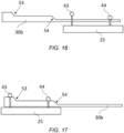
- This is illustrated in Figures 16 and 17 , in which it can be seen that the rollers are laterally offset from one another at all points when moving from the open position of the door 25 ( Figure 16 ) to the closed position of the door 25 ( Figure 17 ), including when traversing the third ramp 53 and fourth ramp 54, respectively.
- third and fourth ramps 53, 54 are arranged to move the third and fourth rollers 43, 44 in tandem with the first and second rollers 41, 42, such that the door 25 is maintained normal to the barrier wall 20 as the door 25 is moved between the open and closed positions.
Landscapes
- Engineering & Computer Science (AREA)
- Aviation & Aerospace Engineering (AREA)
- Mechanical Engineering (AREA)
- Support Devices For Sliding Doors (AREA)
- Wing Frames And Configurations (AREA)
Abstract
An aircraft fuselage (4) comprising: fore (4a) and aft sections (4c) of the aircraft fuselage (4), a barrier wall (20) separating the fore and aft sections and the barrier wall (20) defining an opening (21) therebetween; a rail (30A, 30B) attached to the barrier wall (20); a door (25) moveable across the barrier wall (20) between an open position in which the door (25) is offset from the opening (21) and a closed position in which the door (25) covers the opening (21); a first roller (41) and a second roller (42) each rotatably fixed to the door (25) and moveable on the rail (30A, 30B) along respective first and second paths to move the door (25) between the open and closed positions; wherein the rail (30A, 30B) includes a first ramp (51) configured to engage the first roller (41) as the first roller (41) moves along the first path, the first ramp (51) configured to direct the first roller (41) towards the barrier wall (20), and a second ramp (52) configured to engage the second roller (42) as the second roller (42) moves along the second path, the second ramp (52) configured to direct the second roller (42) towards the barrier wall (20), wherein the first roller (41) is configured to engage the first ramp (51) as the second roller (42) engages the second ramp (52) to move the door (25) towards the barrier wall (20).
Description
- The present invention relates to an aircraft fuselage, and an aircraft comprising the aircraft fuselage.
- A barrier wall may be provided adjacent to the cargo section of a freighter aircraft, the barrier wall intended to arrest forward movement of any cargo containers in the event of an emergency landing or other event. A door provides access through the barrier wall, with the door arranged to provide a tight, smoke-proof seal across the threshold whilst occupying minimal space in the cargo section. The door is thereby arranged to move laterally through the barrier wall between open and closed positions.
- Sealing on lateral sliding doors can be achieved by either using lip/brush seals, which continuously brush against the sealing surface, or by moving the sliding door in the longitudinal direction to compress a seal. Movement of the door in the longitudinal direction is typically achieved with the help of non-linear guide tracks, such as S-shaped rails and curved end rails.
- Generally, lip/brush seals are not compatible where a complete airtight and watertight seal is desired through the threshold of the door. Whilst the use of S-shaped rails, and the like, can increase the space envelope required for the door beyond acceptable limits.
- A first aspect of the invention provides an aircraft fuselage comprising: fore and aft sections of the aircraft fuselage, a barrier wall separating the fore and aft sections and the barrier wall defining an opening therebetween; a rail attached to the barrier wall; a door moveable across the barrier wall between an open position in which the door is offset from the opening and a closed position in which the door covers the opening; a first roller and a second roller each rotatably fixed to the door and moveable on the rail along respective first and second paths to move the door between the open and closed positions; wherein the rail includes a first ramp configured to engage the first roller as the first roller moves along the first path, the first ramp configured to direct the first roller towards the barrier wall, and a second ramp configured to engage the second roller as the second roller moves along the second path, the second ramp configured to direct the second roller towards the barrier wall, wherein the first roller is configured to engage the first ramp as the second roller engages the second ramp to move the door towards the barrier wall.
- This allows the whole door to move towards the barrier wall at the same time, such that the seals on the door/barrier wall engage at the same time across the width of the door.
- A portion of the lateral extent of the first roller between the door and barrier wall may overlap with the lateral extent of the second roller.
- Overlapping lateral extents of the rollers helps minimise the space occupied by the rail.
- The first path may be arranged such that the first roller bypasses the second ramp.
- With this arrangement, the door can be maintained parallel/normal to the barrier wall until both rollers simultaneously engage the respective ramps.
- The first and second rollers may each be retained between a first wall of the rail adjacent the barrier wall and a second wall laterally spaced from the first wall and adjacent the door.
- With this arrangement, the first wall defines a minimum distance of the rollers from the barrier wall and the second wall defines a minimum distance from the door.
- The first and second rollers may be retained by a common first wall.
- This arrangement can better utilise the available space.
- The first and second rollers may each have a width extending parallel to a rotational axis of the respective roller, wherein the width of the second roller is greater than the width of the first roller.
- With this arrangement, the first roller can be thin enough to bypass the second ramp whilst sharing a first wall with the second roller. This can reduce the utilised space.
- The width difference between the first and second rollers may be substantially the same as a height of the second ramp.
- This can minimise the space utilised by the roller whilst providing the space for the first roller to bypass the second ramp.
- The first roller may have a diameter greater than the second roller.
- With this arrangement, the protruding portion of the first roller resultant from its greater diameter can be used to engage the first roller separately from the second roller to provide separate and distinct first and second paths.
- The rail may comprise a first channel defining the first path, and a second channel defining the second path, wherein the first channel is stepped from the second channel.
- With this arrangement, distinct paths can be defined by the step between the channels. The rail may comprise a first channel defining the direction of the first path, the first channel having a width substantially the same as the first roller, and a second channel defining the direction of the second path, the second channel having a width substantially the same as the second roller.
- Each roller can thereby be fixed in position relative to the barrier wall and door.
- The rail may be an upper rail located towards an upper end of the door.
- The aircraft fuselage may comprise a lower rail located towards a lower end of the door.
- Each ramp may be smoothly curved.
- Each ramp may include an inflection point so as to be substantially 'S' shaped.
- The first path and second path may include linear sections either side of a ramp section at which the respective first or second ramp is located.
- A door seal may extend around a periphery of the door and/or a barrier wall seal may extend around a periphery of the opening in the barrier wall for sealing the door against the barrier wall.
- The door may be located on an aft side of the barrier wall.
- The aft side of the fuselage may be a cargo section comprising one or more containers.
- The barrier wall may be attached to a fuselage frame.
- A further aspect of the invention provides an aircraft comprising the aircraft fuselage of the first aspect.
- Embodiments of the invention will now be described with reference to the accompanying drawings, in which:
-
Figure 1 shows an aircraft; -
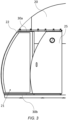
Figure 2 shows a barrier wall attached to a fuselage frame of the aircraft; -
Figure 3 shows a door adjacent the barrier wall in an open position; -
Figure 4 shows the door in a closed position sealed in an opening of the barrier wall; -
Figure 5 shows rollers and a seal attached to the door; -
Figure 6 shows an upper rail on which rollers of the door are moveable; -
Figure 7 shows a lower rail on which rollers of the door are moveable; -
Figure 8 shows a schematic representation of the rollers on the upper rail when the door is in the open position; -
Figure 9 shows a schematic representation of the rollers on the upper rail when the door is in an intermediate position between the open and closed positions of the door; -
Figure 10 shows a schematic representation of the rollers on the upper rail when the door is in the closed position; -
Figure 11 shows an example of the profile of one of the ramps that the roller engages; -
Figure 12 shows a view of the upper rail viewed in the direction of travel from the open position to the closed position of the door; -
Figure 13 shows a view of the upper rail viewed in the direction of travel from the closed position to the open position of the door; -
Figure 14 shows a view of a roller of the lower rail; -
Figure 15 shows a view of the lower rail on which the rollers are mounted; -
Figure 16 shows a schematic representation of the rollers on the lower rail when the door is in the open position; -
Figure 17 shows a schematic representation of the rollers on the lower rail when the door is in the closed position. -
Figure 1 shows anaircraft 1 with port andstarboard wings wing aircraft fuselage 4. - The
fuselage 4 has alongitudinal axis 19 that extends in a fore-aft direction. Thefuselage 4 defines two ormore sections longitudinal axis 19. The example shown inFigure 1 includes acockpit section 4a, acourier section 4b (also referred to as a courier region or supernumerary compartment), and acargo section 4c. Thecargo section 4c is separated from the cockpit andcourier sections cargo section 4a including one ormore cargo containers 8. Thebarrier wall 20 is a structural wall arranged to prevent movement of thecargo containers 8 forward of thebarrier wall 20 in the event of an emergency landing or other in-service event that can accelerate thecargo containers 8 forward. Thebarrier wall 20 may be formed of metal or other suitable material such as carbon fibre reinforced polymer (CFRP). -
Figure 2 shows an example of abarrier wall 20. Thebarrier wall 20 is attached to the aircraft structure by afuselage frame 10. Thefuselage frame 10 is a transverse member lying in a plane normal to thelongitudinal axis 19 of thefuselage 4 and arranged to support the aircraft skin (not shown) to define a cross-section of thefuselage 4. Thefuselage 4 may include a plurality of fuselage frames 10 spaced along thelongitudinal axis 19 of thefuselage 4. The fuselage frames 10 may be formed of metal or other suitable material. - The
barrier wall 20 extends across an upper portion of thefuselage frame 10. Thebarrier wall 20 may extend from a floor level (indicated generally by longitudinal andtransverse beams 11, 12) to an upper-mostinner edge 10a of thefuselage frame 10, although it will be appreciated that thebarrier wall 20 may extend across any suitable portion of thefuselage frame 10. - The
barrier wall 20 defines an opening 21 (SeeFigure 3 ), in particular anopening 21 between thecourier section 4b and thecargo section 4c. Adoor 25 is attached to thebarrier wall 20 via upper andlower rails door 25 moveable on therails door 25 moves in a straight line across thebarrier wall 20 between an open position in which thedoor 25 is offset from theopening 21 and a closed position in which thedoor 25 covers theopening 21. - The
door 25 is arranged to seal theopening 21 in the closed position so as to prevent the spread of smoke through theopening 21 in the event of a fire in thecargo section 4c. -
Figure 3 shows thedoor 25 in an open position in which thedoor 25 is offset from theopening 21. Thedoor 25 is preferably entirely offset from the opening when viewed in a plane normal to thelongitudinal axis 19 of thefuselage 4, although it may be partially offset in some examples. -
Figure 4 shows thedoor 25 in a closed position in which thedoor 25 entirely covers theopening 21 with thedoor 25 sealed against thebarrier wall 20 to prevent the passage of smoke across thebarrier wall 20. - The allowable space for the
door 25 and door mechanism (in this case arail cargo section 4c is limited so as to maximise the available space forcargo containers 8 and other like items. For instance, the available space within thecargo section 4c may be less than 100mm in the direction of thelongitudinal axis 19 of thefuselage 4. A system that allows thedoor 25 to adequately seal over theopening 21 in thebarrier wall 20 is therefore needed that minimises the space required, whilst ensuring the longevity of the seals on thebarrier wall 20 anddoor 25. - As shown in
Figures 3 and5 , abarrier wall seal 22 extends around the periphery of theopening 21 and is configured to seal against adoor seal 26 that extends around a periphery of thedoor 25 when thedoor 25 is in the closed position. -
Figure 5 shows a set of rollers rotatably fixed to thedoor 25 by a fixture, such as the connectingbracket 37a shown inFigure 6 . Afirst roller 41 and asecond roller 42 are arranged to move along theupper rail 30a in which aroller guard 31a helps retain therollers rail 30a (SeeFigure 6 ). Eachroller upper rail 30a. The paths can be considered as defining a swept volume of therespective roller door 25 moves between the open and closed positions. Similarly, athird roller 43 and afourth roller 44 are arranged to move along thelower rail 30b in which aroller guard 31b help retain therollers rail 30b (SeeFigure 7 ) - The
upper rail 30a includes afirst ramp 51 configured to engage thefirst roller 41 as thefirst roller 41 moves along the first path so as to divert the direction of thefirst roller 41. Similarly, theupper rail 30a includes asecond ramp 52 configured to engage thesecond roller 42 as thesecond roller 42 moves along the second path so as to divert the direction of thesecond roller 41. - In this manner, the
first ramp 51 andsecond ramp 52 direct thedoor 25 towards thebarrier wall 20 as thefirst roller 41 andsecond roller 42 engage therespective ramps door seal 26 thereby seals against thebarrier wall seal 22. - In order to reduce wear on the
seals door 25 translates perpendicular to thebarrier wall 20 without rotation to minimise lateral moving contact between theseals second rollers ramps first roller 41 engages thefirst ramp 51 as thesecond roller 42 engages thesecond ramp 52. The first andsecond ramps -
Figures 8 to 10 illustrate schematically an example in which therollers respective ramps first roller 41 bypasses thesecond ramp 52 such that thefirst roller 41 does not contact thesecond ramp 52 as it passes by. With this arrangement, the maximum travel of thedoor 25 between the open and closed positions is not restricted by the distance between theramps door 25 only translates perpendicular to thebarrier wall 20 without rotation. In other words, the plane of thedoor 25 remains parallel to the plane of thebarrier wall 20 during movement up/down theramps - As indicated on
Figure 8 , thefirst roller 41 has a first width W1. Similarly, thesecond roller 42 has a second width W2. The widths W1, W2 are defined as the extent of therespective roller respective roller rollers door 25 andbarrier wall 20. - The
first roller 41 has smaller width W1 than the second roller W2. In this manner, the roller assembly can be arranged such that the first andsecond rollers common rail 30a whilst also engagingseparate ramps ramp other roller first roller 41 can bypass the second ramp 52 (as evident fromFigure 9 ). This allows the first andsecond rollers door 25 and the barrier wall 20) that overlap to minimise the lateral space required by therail 30a, in contrast to a design in which eachroller second roller 42 that might be required to ensure structural integrity. - In the example shown, the width of the
ramps second ramp 52, is substantially equal to the difference in width between the first andsecond rollers second roller 42 and therail 30a surfaces. This arrangement provides the minimum width of therail 30a to ensure thefirst roller 41 bypasses thesecond ramp 52 such that therollers respective ramps Figures 9 and 10 ). - It will be appreciated that the chamfered profile of the
ramps Figures 8 to 10 is merely illustrative of the gradient provided by theramps door 25 towards thebarrier wall 20. As shown inFigure 11 for thefirst ramp 51, but similarly applicable to thesecond ramp 52, theramp 51 is smoothly curved. In particular, theramp 51 includes an inflection point so as to provide a substantially 'S' shapedramp 51. The first path is thereby split into a firstlinear section 38a, a secondlinear section 38c, and a curved 'ramp'section 38b between thelinear sections - The
rail 30a includes twochannels first channel 32 defines the first path along which thefirst roller 41 is moveable, and asecond channel 33 defines the second path along which thesecond roller 42 is moveable. Thechannels rollers rollers ramps first channel 32 has a width substantially the same as the width of thefirst roller 41, and thesecond channel 33 has a width substantially the same as the width of thesecond roller 42. - To accommodate these separate paths constraining lateral movement of the
roller first channel 32 is stepped from thesecond channel 33, as shown inFigures 12 and 13 . In particular, the surface on which thefirst roller 41 rolls is stepped from the surface on which thesecond roller 42 rolls. In this way, therollers rollers Figures 12 and 13 show thedoor 25 in the closed position, such that therollers ramps - The
first channel 32 andsecond channel 33 each have respective first and second walls that retain therollers first channel 32 hasfirst wall 34 adjacent thebarrier wall 20 and asecond wall 35 adjacent thedoor 25 against which thefirst roller 41 can abut. Thefirst roller 41 is retained between the first andsecond walls first wall 34 andsecond wall 35 are laterally offset from one another, such that the first path is defined between the first andsecond walls first wall 34 defines a minimum distance between thefirst roller 41 and thebarrier wall 20 and thesecond wall 35 defines a minimum distance between thefirst roller 41 and thebarrier wall 20. Similarly, thesecond channel 33 has afirst wall 34 adjacent thebarrier wall 20 and asecond wall 36 adjacent thedoor 25 against which thesecond roller 42 can abut. Thesecond roller 42 is retained between the first andsecond walls first wall 34 andsecond wall 36 are laterally offset from one another, such that the second path is defined between the first andsecond walls first wall 34 defines a minimum distance between thesecond roller 42 and thebarrier wall 20 and thesecond wall 36 defines a minimum distance between thesecond roller 42 and thebarrier wall 20. The first andsecond channels first wall 34 as this can minimise the space required to accommodate therollers - To provide the
step 39 between the first andsecond channels rollers first roller 41 may have a greater diameter than the diameter of thesecond roller 42. This can allow the same connectingbracket 37a to be used for each roller. - It will be appreciated that the third and
fourth rollers lower rail 30b, may be similarly arranged. - As shown in the
Figures 14 and 15 , the third andfourth rollers lower rail 30b may be arranged to withstand primarily lateral forces of therollers door 25. The weight of thedoor 25 would therefore be carried by the first andsecond rollers upper rail 30a. - In this case, the third and
fourth rollers door 25 andbarrier wall 20, and perpendicular to the rotational axes of the first andsecond rollers - Whilst the present example may include the separate channels, such as those discussed in relation to the
upper rail 30b, it will be appreciated that the orientation of the rotational axes means that theroller bracket 37b that biases therollers lower rail 30b (SeeFigure 14 ). - The reduced load acting on the third and
fourth rollers fourth rollers second rollers door 25 andbarrier wall 20. Consequently, there may be no need for the lateral extents of the third andfourth rollers second rollers Figures 16 and 17 , in which it can be seen that the rollers are laterally offset from one another at all points when moving from the open position of the door 25 (Figure 16 ) to the closed position of the door 25 (Figure 17 ), including when traversing thethird ramp 53 andfourth ramp 54, respectively. It will be appreciated that the third andfourth ramps fourth rollers second rollers door 25 is maintained normal to thebarrier wall 20 as thedoor 25 is moved between the open and closed positions. - Where the word 'or' appears this is to be construed to mean 'and/or' such that items referred to are not necessarily mutually exclusive and may be used in any appropriate combination.
- Although the invention has been described above with reference to one or more preferred embodiments, it will be appreciated that various changes or modifications may be made without departing from the scope of the invention as defined in the appended claims.
Claims (15)
- An aircraft fuselage comprising:fore and aft sections of the aircraft fuselage, a barrier wall separating the fore and aft sections and the barrier wall defining an opening therebetween;a rail attached to the barrier wall;a door moveable across the barrier wall between an open position in which the door is offset from the opening and a closed position in which the door covers the opening;a first roller and a second roller each rotatably fixed to the door and moveable on the rail along respective first and second paths to move the door between the open and closed positions;wherein the rail includes a first ramp configured to engage the first roller as the first roller moves along the first path, the first ramp configured to direct the first roller towards the barrier wall, and a second ramp configured to engage the second roller as the second roller moves along the second path, the second ramp configured to direct the second roller towards the barrier wall,wherein the first roller is configured to engage the first ramp as the second roller engages the second ramp to move the door towards the barrier wall.
- The aircraft fuselage of claim 1, wherein a portion of the lateral extent of the first roller between the door and barrier wall overlaps with the lateral extent of the second roller.
- The aircraft fuselage of claim 1 or 2, wherein the first path is arranged such that the first roller bypasses the second ramp.
- The aircraft fuselage of any preceding claim, wherein the first and second rollers are each retained between a first wall of the rail adjacent the barrier wall and a second wall laterally spaced from the first wall and adjacent the door.
- The aircraft fuselage of claim 4, wherein the first and second rollers are retained by a common first wall.
- The aircraft fuselage of any preceding claim, wherein the first and second rollers each have a width extending parallel to a rotational axis of the respective roller, wherein the width of the second roller is greater than the width of the first roller.
- The aircraft fuselage of any preceding claim, wherein the first roller has a diameter greater than the second roller.
- The aircraft fuselage of any preceding claim, wherein the rail comprises a first channel defining the first path, and a second channel defining the second path, wherein the first channel is stepped from the second channel.
- The aircraft fuselage of any preceding claim, wherein the rail comprises a first channel defining the direction of the first path, the first channel having a width substantially the same as the first roller, and a second channel defining the direction of the second path, the second channel having a width substantially the same as the second roller.
- The aircraft fuselage of any preceding claim, wherein the rail is an upper rail located towards an upper end of the door.
- The aircraft fuselage of any preceding claim, wherein each ramp is smoothly curved.
- The aircraft fuselage of any preceding claim, wherein each ramp includes an inflection point so as to be substantially 'S' shaped.
- The aircraft fuselage of any preceding claim, wherein the first path and second path include linear sections either side of a ramp section at which the respective first or second ramp is located.
- The aircraft fuselage of any preceding claim, wherein a door seal extends around a periphery of the door and/or a barrier wall seal extends around a periphery of the opening in the barrier wall for sealing the door against the barrier wall.
- An aircraft comprising the aircraft fuselage of any preceding claim.
Applications Claiming Priority (1)
| Application Number | Priority Date | Filing Date | Title |
|---|---|---|---|
| IN202311058863 | 2023-09-01 |
Publications (1)
| Publication Number | Publication Date |
|---|---|
| EP4516666A1 true EP4516666A1 (en) | 2025-03-05 |
Family
ID=92456986
Family Applications (1)
| Application Number | Title | Priority Date | Filing Date |
|---|---|---|---|
| EP24194768.8A Pending EP4516666A1 (en) | 2023-09-01 | 2024-08-15 | An aircraft fuselage |
Country Status (3)
| Country | Link |
|---|---|
| US (1) | US20250074574A1 (en) |
| EP (1) | EP4516666A1 (en) |
| CN (1) | CN119551178A (en) |
Citations (5)
| Publication number | Priority date | Publication date | Assignee | Title |
|---|---|---|---|---|
| US6010286A (en) * | 1997-03-13 | 2000-01-04 | Mcdonald Douglas Corporation | Apparatus for rigidly retaining cargo |
| FR2945027A1 (en) * | 2009-04-30 | 2010-11-05 | Airbus France | Rigid stop partition for separating section of cabin of aircraft into zones e.g. cargo zone, has vents balancing pressure on sides of partition, and mechanical connection comprising rod and connecting partition to structure of aircraft |
| US20110315822A1 (en) * | 2010-06-23 | 2011-12-29 | Greenpoint Technologies, Inc. | Door apparatus and method |
| US20160245006A1 (en) * | 2015-02-24 | 2016-08-25 | Airbus Helicopters Deutschland GmbH | Sliding closing element, in particular a sliding door or a sliding window, for a sliding closing element arrangement of a vehicle, in particular of an aircraft |
| US20200386025A1 (en) * | 2017-04-25 | 2020-12-10 | Assa Abloy Entrance Systems Ab | Sliding door arrangement |
Family Cites Families (6)
| Publication number | Priority date | Publication date | Assignee | Title |
|---|---|---|---|---|
| US3334375A (en) * | 1965-08-04 | 1967-08-08 | American Metal Climax Inc | Caster for sliding panel |
| US3611637A (en) * | 1970-03-04 | 1971-10-12 | Joseph N Saino | Sliding door assembly |
| US4569164A (en) * | 1983-04-08 | 1986-02-11 | Advanced Equipment Corp. | Operable wall system |
| US5016318A (en) * | 1989-07-13 | 1991-05-21 | Panelfold, Inc. | Multi-directional radial wheel trolley and track for operable walls |
| US7610718B2 (en) * | 2007-11-15 | 2009-11-03 | Krueger International, Inc. | Sliding door with lateral sealing movement |
| US9470028B2 (en) * | 2013-05-06 | 2016-10-18 | Gregory A. Header | Sliding door assembly |
-
2024
- 2024-08-15 EP EP24194768.8A patent/EP4516666A1/en active Pending
- 2024-08-29 US US18/819,322 patent/US20250074574A1/en active Pending
- 2024-08-29 CN CN202411196992.XA patent/CN119551178A/en active Pending
Patent Citations (5)
| Publication number | Priority date | Publication date | Assignee | Title |
|---|---|---|---|---|
| US6010286A (en) * | 1997-03-13 | 2000-01-04 | Mcdonald Douglas Corporation | Apparatus for rigidly retaining cargo |
| FR2945027A1 (en) * | 2009-04-30 | 2010-11-05 | Airbus France | Rigid stop partition for separating section of cabin of aircraft into zones e.g. cargo zone, has vents balancing pressure on sides of partition, and mechanical connection comprising rod and connecting partition to structure of aircraft |
| US20110315822A1 (en) * | 2010-06-23 | 2011-12-29 | Greenpoint Technologies, Inc. | Door apparatus and method |
| US20160245006A1 (en) * | 2015-02-24 | 2016-08-25 | Airbus Helicopters Deutschland GmbH | Sliding closing element, in particular a sliding door or a sliding window, for a sliding closing element arrangement of a vehicle, in particular of an aircraft |
| US20200386025A1 (en) * | 2017-04-25 | 2020-12-10 | Assa Abloy Entrance Systems Ab | Sliding door arrangement |
Also Published As
| Publication number | Publication date |
|---|---|
| CN119551178A (en) | 2025-03-04 |
| US20250074574A1 (en) | 2025-03-06 |
Similar Documents
| Publication | Publication Date | Title |
|---|---|---|
| US5181677A (en) | Sliding aircraft door | |
| US6189833B1 (en) | Aircraft sliding door system | |
| US5259576A (en) | External sliding aircraft door | |
| US8511610B2 (en) | Device for closing an aircraft door, aircraft comprising such a device | |
| US9038964B2 (en) | Control surface assembly | |
| EP2690018B1 (en) | Hybrid hinge and latch beam | |
| US8690103B2 (en) | Method and apparatus for converting aircraft from commercial to military freight service | |
| CN108791809B (en) | Aircraft wing | |
| EP3601049B1 (en) | Galley trolley compartment doors | |
| CN106043706B (en) | Overhead stowage bin assembly for a vehicle | |
| US20120248713A1 (en) | Weatherproof surround for safely jettisoning a removable panel | |
| US12017756B2 (en) | Structural assembly for an aircraft | |
| CN114599583A (en) | Passenger Seating Unit with Multi-Slide Sliding Door | |
| US11401035B2 (en) | Cargo doors for payload bay having internal payload extension and retraction mechanism | |
| US11691732B2 (en) | Modular multiple-egress doors for dual occupancy aircraft passenger suites | |
| US10543919B2 (en) | Aircraft cabin and partition assembly therefor | |
| US20250074574A1 (en) | Aircraft fuselage | |
| GB2634942A (en) | An aircraft fuselage | |
| US11530024B2 (en) | Variable width door for cockpit secondary barrier and other aircraft cabin applications | |
| CN106985998B (en) | Aircraft door with retractable head | |
| US10597135B2 (en) | Aircraft cell comprising a door opening in rectilinear translation | |
| EP4662115A1 (en) | Aircraft fuselage with barrier wall | |
| US11370547B2 (en) | Mobile class divider for aircraft cabin | |
| GB2628407A (en) | Aircraft fuselage | |
| EP4053013B1 (en) | Hybrid pressure deck for aircraft |
Legal Events
| Date | Code | Title | Description |
|---|---|---|---|
| PUAI | Public reference made under article 153(3) epc to a published international application that has entered the european phase |
Free format text: ORIGINAL CODE: 0009012 |
|
| STAA | Information on the status of an ep patent application or granted ep patent |
Free format text: STATUS: THE APPLICATION HAS BEEN PUBLISHED |
|
| AK | Designated contracting states |
Kind code of ref document: A1 Designated state(s): AL AT BE BG CH CY CZ DE DK EE ES FI FR GB GR HR HU IE IS IT LI LT LU LV MC ME MK MT NL NO PL PT RO RS SE SI SK SM TR |
|
| STAA | Information on the status of an ep patent application or granted ep patent |
Free format text: STATUS: REQUEST FOR EXAMINATION WAS MADE |
|
| 17P | Request for examination filed |
Effective date: 20250826 |