EP4516665A1 - Boat with an energy recovering apparatus - Google Patents
Boat with an energy recovering apparatus Download PDFInfo
- Publication number
- EP4516665A1 EP4516665A1 EP24195822.2A EP24195822A EP4516665A1 EP 4516665 A1 EP4516665 A1 EP 4516665A1 EP 24195822 A EP24195822 A EP 24195822A EP 4516665 A1 EP4516665 A1 EP 4516665A1
- Authority
- EP
- European Patent Office
- Prior art keywords
- support
- blade
- hull
- trajectory
- rotor
- Prior art date
- Legal status (The legal status is an assumption and is not a legal conclusion. Google has not performed a legal analysis and makes no representation as to the accuracy of the status listed.)
- Pending
Links
Images



Classifications
-
- B—PERFORMING OPERATIONS; TRANSPORTING
- B63—SHIPS OR OTHER WATERBORNE VESSELS; RELATED EQUIPMENT
- B63J—AUXILIARIES ON VESSELS
- B63J3/00—Driving of auxiliaries
- B63J3/04—Driving of auxiliaries from power plant other than propulsion power plant
-
- B—PERFORMING OPERATIONS; TRANSPORTING
- B63—SHIPS OR OTHER WATERBORNE VESSELS; RELATED EQUIPMENT
- B63B—SHIPS OR OTHER WATERBORNE VESSELS; EQUIPMENT FOR SHIPPING
- B63B35/00—Vessels or similar floating structures specially adapted for specific purposes and not otherwise provided for
- B63B2035/009—Wind propelled vessels comprising arrangements, installations or devices specially adapted therefor, other than wind propulsion arrangements, installations, or devices, such as sails, running rigging, or the like, and other than sailboards or the like or related equipment
-
- B—PERFORMING OPERATIONS; TRANSPORTING
- B63—SHIPS OR OTHER WATERBORNE VESSELS; RELATED EQUIPMENT
- B63J—AUXILIARIES ON VESSELS
- B63J3/00—Driving of auxiliaries
- B63J2003/001—Driving of auxiliaries characterised by type of power supply, or power transmission, e.g. by using electric power or steam
- B63J2003/002—Driving of auxiliaries characterised by type of power supply, or power transmission, e.g. by using electric power or steam by using electric power
-
- B—PERFORMING OPERATIONS; TRANSPORTING
- B63—SHIPS OR OTHER WATERBORNE VESSELS; RELATED EQUIPMENT
- B63J—AUXILIARIES ON VESSELS
- B63J3/00—Driving of auxiliaries
- B63J3/04—Driving of auxiliaries from power plant other than propulsion power plant
- B63J2003/046—Driving of auxiliaries from power plant other than propulsion power plant using wind or water driven turbines or impellers for power generation
Definitions
- the invention relates to a boat, in particular a sailing boat, more in particular a racing boat, with an apparatus for recovering energy.
- Some racing boats are provided with a plurality of energy-consuming devices, such as hydraulic actuators, charging devices for charging batteries and the like.
- these devices are powered by energy produced by an internal combustion engine on board the boat.
- the engine in turn, is powered by fossil fuels.
- This aspect leads to some drawbacks, including the emission of pollutants produced by the combustion of fossil fuel and the sizing of the devices closely related to the amount of fuel on board the boat.
- Aim of the invention is to fulfil at least one of the needs discussed above.
- the boat has a hull 2 extending longitudinally along an axis X, which coincides with the normal sailing direction of the boat.
- the boat 1 preferably comprises a keel 3, which projects downwards along an axis 4 starting from a portion 5 of the hull 2, arranged in an intermediate position between the bow and the stern and at the centre between the sides of the hull 2.
- the portion 5 is the lowest part of the hull 2.
- the axis 4 is orthogonal to the axis X.
- the keel 3 has a lower end that supports or defines a bulb 6, having a mass (for example of about 8-10 tons) such as to place the centre of gravity of the boat 1 in a relatively low position, in particular in order to enable a self-righting of the boat 1 even in case of a possible total capsizing.
- the keel 3 is coupled to the hull 2 at its upper end so as to be able to rotate relative to the Z axis, due to the action of an actuator, about an axis which is parallel to the X axis, in particular to move the bulb 6 to the right or left.
- the boat 1 comprises a blade 10, which is arranged below the hull 2 so as to be permanently and completely immersed in water and has a shape and/or structure and/or dimensions such as to define a hydrodynamic lift and/or a hydrodynamic resistance as a result of a relative speed in relation to the water in which it is immersed.
- the blade 10 is supported by the keel 3 and protrudes with respect to the keel 3 in a way that is not shown, along an axis 11 transverse to the axes X and Z.
- the blade 10 is mounted on a support 12, for example defined by a shaft or a rod, sliding together with the blade 10 relative to the keel 3 and the hull 2 along a trajectory K defined by a guide 13 (schematically shown).
- a guide 13 (schematically shown).
- the trajectory K is straight and coincides with the axis 4.
- the guide 13 can be part of the keel 3 or is arranged inside the hull 2.
- two blades 10 are provided, on opposite sides of the support 12.
- the keel 3 lacks the bulb 6; or the blade 10 is arranged on a keel other than the keel 3 that supports the bulb 6; or the support 12 with the blade 10 projects downwards from the hull 2 without being supported by, or associated with, any keel; and/or the support 12 with the blade 10 is arranged in a longitudinal position other than the one shown herein (for example, it can be arranged at the bow).
- the blade 10 has an external configuration that can be changed to vary its hydrodynamic lift and/or its hydrodynamic resistance along the trajectory K.
- the way in which to change the external configuration is not essential and, for example, it can consist of:
- the external configuration of the blade 10 is changed by operating an actuator 14, of the linear or rotary type, preferably powered by electric energy.
- the actuator 14 is carried by the support 12 and, hence, is movable together with the blade 10 and the support 12 along the trajectory K defined by the guide 13.
- the actuator 14 and the lower part of the support 12 are housed in the keel 3 and the latter has a lateral slit (not shown), which is parallel to the trajectory K and allows the blade 10 (which is external to the keel 3) and the lower part of the support 12 (which is internal to the keel 3) to be coupled to one another.
- a transmission which is not shown, can be provided between the actuator 14 and the blade 10.
- the activation of the actuator 14 is controlled by an electronic control unit 15 (schematically shown), whose functions will be described more in detail below.
- the blade 10, the support 12, the actuator 14 and the electronic control unit 15 are part of an apparatus 16 for energy recovery, which exploits the hydrodynamic lift and/or the hydrodynamic resistance generated by the blade 10 in response to a movement of the boat 1 relative to the water and, therefore, in response to a relative movement between the water and the blade 10.
- the apparatus 16 can be configured according to two preferred embodiments, one exploiting the movement of the boat 1 during navigation to generate hydrodynamic lift along the trajectory K and the other exploiting the natural oscillatory pitching movement of the bow of the boat 1, triggered by the wave motion of the sea, to generate hydrodynamic resistance along the trajectory K.
- the support 12 moves with a reciprocating motion along the direction K due to the effect of the hydrodynamic lift of the blade 10 (as also described below with reference to figures 5 to 10 ) or due to the effect of the hydrodynamic resistance of the blade 10.
- This reciprocating motion can take place, at most, between an upper end-of-stroke position and a lower end-of-stroke position, defined for example by reference elements and/or stop elements that are not shown herein.
- the reciprocating motion actually takes place between a top dead centre and a bottom dead centre, which could coincide with the aforementioned end-of-stroke positions.
- the apparatus 16 further comprises at least one electric generator 18.
- the generator 18 comprises a rotor 19, which can rotate about an axis R.
- the generator 18 is configured to convert a kinetic energy associated with a rotation of the rotor 19 (in fact, the kinetic energy of the rotation of the rotor 19) into electric energy.
- the electric energy produced by the generator 18 can be stored in a power storage device, on board the boat 1, such as a battery (not shown), used to power the electric utilities of the boat 1.
- a power storage device on board the boat 1, such as a battery (not shown), used to power the electric utilities of the boat 1.
- the rotor 19 is coupled to the support 12 by means of a transmission mechanism 20 so as to rotate in response to the translation of the support 12.
- the mechanism 20 transforms the reciprocating translatory motion of the support 12 along the trajectory K into a corresponding rotation of the rotor 19 about the axis R, in particular a continuous rotation according to a single direction of rotation, for example clockwise or counterclockwise.
- a first translation of the support 12, followed by a second translation of the support 12 in the opposite direction relative to the first translation causes, as a whole, a rotation, for example clockwise or counterclockwise, of the rotor 19 according to the single direction of rotation, namely without the latter changing with the shift from the first translation to the second translation.
- the term “continuous” refers precisely to the absence of a reversal of the direction of rotation of the rotor 19 due to the reversal of the direction of translation of the support 12 shifting from the first translation to the second translation. Therefore, the term “continuous” should not be understood in the restrictive sense that the angular speed of the rotor 19 cannot in any case be zero at one or more moments of time.
- the mechanism 20 comprises two transmissions 21, 22 arranged in parallel and configured to transmit respective rotations to the rotor 19.
- the transmissions 21, 22 are configured to convert the first translation and the second translation, respectively, of the support 12 into rotary motions and then selectively transmit such rotary motions so as to cause the rotor 19 to rotate about the axis R according to the single rotation direction.
- the transmission 21 converts the first translation into a rotary motion and transmits the latter to the rotor 19
- the transmission 22 does not transmit any rotation torque to the rotor 19; vice versa
- the transmission 22 converts the second translation into a rotary motion and transmits the latter to the rotor 19, the transmission 21 does not transmit any rotation torque to the rotor 19.
- the transmissions 21, 22 comprise respective decoupling devices 23, 24 configured to decouple the rotation of the rotor 19 from the translation of the support 12 and/or to interrupt the respective couplings between the rotor 19 and the support 12.
- Each one of the decoupling devices 23, 24, independently of the other one, can be defined by:
- control unit 15 controls the activation of the clutch device as a function of one or more quantities corresponding to or indicative of the direction of translation and, preferably, of the speed of translation of the support 12. These quantities are acquired by the control unit 15 by means of dedicated transducers (not shown) configured to detect the quantities.
- the transmissions 21, 22 comprise respective racks 25 and 26, on opposite sides of the support 12, meshing with respective pinions 27 and 28, which can rotate about fixed axes, parallel to one another and orthogonal to the direction K.
- the transmissions 21, 22 further comprise respective toothed wheels 29, 30, which are respectively coupled to the pinions 27,28 by means of the corresponding devices 23, 24 and rotate in the same direction as the pinions 27, 28, when the respective devices 23, 24 transmit rotation torque.
- the wheels 29 and 30 are coaxial to the pinions 27 and 28, respectively.
- the wheels 29, 30 both mesh with a toothed wheel 31, which operates the rotor 19 of the generator 18.
- the wheel 31 is coaxial and fixed relative to the rotor 19.
- the devices 23, 24 are both configured to decouple the rotor 19 when the pinions 27, 28 rotate according to a same specific direction of rotation, for example clockwise or counterclockwise, so as to transmit torque only in the opposite direction of rotation.
- the wheel 31 and, hence, the rotor 19 can only rotate by means of a single one of the transmissions 21, 22 and according to one single direction of rotation.
- the devices 23, 24 allow only one of the wheels 29, 30 to rotate and only in the direction contrary to the specific one, mentioned above, in which the wheels 29,30 are decoupled from the support 12.
- the wheels 29 and 30 When they are decoupled from the support 12, the wheels 29 and 30 continue to rotate always in the same direction of rotation, but idle, dragged by the meshing with the wheel 31.
- the mechanism 20 schematically represented in figure 3 is one of the possible mechanisms conceivable for transforming the reciprocating translatory motion of the support 12 into a rotation of the rotor 19 according to a single rotation direction.
- the mechanism 20 could for example comprise a typical connecting rod-crank mechanism, whose properties are well known and do not need to be described in detail.
- the mechanism 20 comprises one single transmission (for example defined by the pinion 27 or 28), which converts the translatory motion of the support 12 into a rotary motion and transfers the latter to the rotor 19, which, hence, rotates with a reciprocating rotary motion about the axis R (without a decoupling device interposed between the rotor 19 and the support 12): suitable electric/electronic devices are then provided to process and store the generated electric energy (which has an oscillating intensity and also reaches zero values at the top and bottom dead centres of the translation of the blade 10).
- suitable electric/electronic devices are then provided to process and store the generated electric energy (which has an oscillating intensity and also reaches zero values at the top and bottom dead centres of the translation of the blade 10).
- the generator 18, of the rotary type is replaced by a generator of electric energy of the linear type, for example by a linear alternator: in this case, the mechanism 20 could be absent, namely said generator could be directly coupled to the support 12.
- the apparatus 16 of the boat 1 works as follows, with reference to figures 5 to 10 , where the boat 1 is navigating, for example due to the thrust of the wind (sailing).
- the external configuration of the blade 10 defines a hydrodynamic airfoil that is set/adjusted by operating the actuator 14, so as to have a first hydrodynamic lift directed upwards, namely towards the hull 2, due to the effect of the relative movement between the airfoil 10 and the water along the navigation direction.
- This first hydrodynamic lift corresponds to a thrust that causes the blade 10 to translate along the trajectory K towards the hull 2 ( figure 6 ) until it reaches the top dead centre ( figure 7 ).
- the external configuration (i.e. the airfoil) of the blade 10 is automatically changed by the control unit 15: the latter operates the actuator 14 so as to reverse the direction of thrust of the hydrodynamic lift, namely so as to have a second hydrodynamic lift directed in the opposite direction relative to the hull 2 (always considering the hydrodynamic effects caused by the movement along the navigation direction).
- the blade 10 reverses the direction of translation, as the hydrodynamic thrust is now directed downwards ( figure 9 ).
- the actuator 14 is automatically actuated by the control unit 15 to reverse again the direction in which the hydrodynamic lift is directed and, hence, obtain again a hydrodynamic lift and a translation facing upwards along the direction K.
- the top and bottom dead centres are located along the trajectory K in respective positions that are predefined and fixed (if necessary, adjustable during the initial setting of the apparatus 16, but anyway stable after said initial setting).
- the top and bottom dead centres respectively correspond to the end-of-travel positions provided for the translation, so as to take advantage of the maximum stroke available in each one of the two directions of translation.
- control unit 15 is connected to suitable sensors, for example proximity sensors or position sensors (not shown), for these two positions, to detect the reaching of the top and bottom dead centres by the support 12 and/or the blade 10 and then supply corresponding consent signals to the control unit 15.
- suitable sensors for example proximity sensors or position sensors (not shown), for these two positions, to detect the reaching of the top and bottom dead centres by the support 12 and/or the blade 10 and then supply corresponding consent signals to the control unit 15.
- the latter controls the actuator 14 in response to said consent signals, namely exactly when the blade and the support 12 have reached the top and bottom dead centres.
- the external configuration of the blade 10 is set/adjusted by the control unit 15 through the actuator 14 at the top and bottom dead centres so as to have a first and a second hydrodynamic resistance, which are directed along the trajectory K in directions contrary to the lifting and to the lowering, respectively, of the boat 1, namely in counter-phase with respect to the pitching movement.
- a first hydrodynamic resistance of the blade 10 is set so as to hold blade 10 down, whereby the support 12 slides in the guide 13 which, in the meantime, is rising together with the hull 2; similarly, when the wave motion causes a lowering of the hull 2, the external configuration of the blade 10 is reversed, namely a second hydrodynamic resistance is set so as to hold the blade 10 up, whereby the support 12 slides in the opposite direction in the guide 13, which, in the meantime, is lowering itself together with the hull 2.
- control unit 15 is configured so as to have, as its objective or target, maintaining the blade 10 in the vicinity of a fixed depth with respect to the free surface of the water, while the hull 2 pitches naturally.
- the top and bottom dead centres where the switching of the external configuration of the blade 10 must take place, are not located in fixed positions, but depend on the actual range of the hull 2 during the pitching (and, hence, on the extent of the wave motion).
- the top dead centre and the bottom dead centre of the translation of the blade 10 and of the support 12 correspond to the bottom dead centre and to the top dead centre, respectively, of the oscillation of the hull 2 during pitching.
- the electronic control unit 15 is configured so as to synchronize the activation of the actuator 14 and, hence, the switching of the external configuration of the blade 10 with the pitching oscillation motion of the hull 2.
- the control unit 15 is connected to suitable sensors, for example inertial sensors or IMUs (not shown), located on the hull 2 and configured so as to detect the angle of orientation of the hull 2 about the transverse pitch axis.
- the control unit 15 receives the signals emitted by these sensors and is configured so as to
- the generation of electric energy in the generator 18 causes a mechanical resistance that counters the translation of the support 12: the dimensions and shapes in the various configurations of the blade 10 are established by design so as to guarantee a sufficient hydrodynamic lift (when exploiting the navigation of the boat 1) or a sufficient hydrodynamic resistance (when exploiting the pitch of the hull 2) to overcome the mechanical resistance exerted by the generator 18 during the production of electric energy (in addition to overcoming the resistance caused by frictions in the coupling to the guide 13, frictions and inertias of the mechanism 20, inertia of the rotor 19, etc.).
- the simple use of the boat 1 allows for the generation of an alternative movement of the blade 10 and of the support 12, which, in turn, can be exploited to generate electric energy through the generator 18.
- the electric energy can be directly used to power the electric utilities of the boat 1 or stored in one or more electric energy storage devices, such as batteries, capacitors and the like.
- the external shape of the blade 10 and the dimensional proportions relative to the other components of the boat 1 can be different from the ones schematically shown herein by way of non-limiting example.
- the support 12 could be provided with a rotary motion, instead of having translatory motion, so that the trajectory K could be curved, instead of being straight.
- a system could be provided to retract the blade 10 and the lower part of the support 12, to bring them out of the water (for example into the hull 2), when the generator 18 is not in use.
Landscapes
- Chemical & Material Sciences (AREA)
- Engineering & Computer Science (AREA)
- Combustion & Propulsion (AREA)
- Mechanical Engineering (AREA)
- Ocean & Marine Engineering (AREA)
- Other Liquid Machine Or Engine Such As Wave Power Use (AREA)
Abstract
A boat (1) has a hull (2) and an apparatus (16) with an electric generator (18) for electric energy recovery; the apparatus (16) has a support (12), which is movable with respect to the hull (2) with a reciprocating motion along a trajectory (K), is coupled to the electric generator (18) so as to generate electric energy due to the movement between a top dead centre and a bottom dead centre along said trajectory (K) and carries a blade (10), arranged below the hull (2) so as to be permanently and completely arranged in the water during the use of the electric generator (18); the apparatus (16) has an actuator (14), which is operated by an electronic control unit (15) to vary an external configuration of the blade (10) and, hence, change a hydrodynamic lift or a hydrodynamic resistance along said trajectory (K) when the support (12) and the blade (10) reach the top and bottom dead centres.
Description
- This patent application claims priority from
Italian patent application no. 102023000017688 filed on August 29, 2023 - The invention relates to a boat, in particular a sailing boat, more in particular a racing boat, with an apparatus for recovering energy.
- Some racing boats are provided with a plurality of energy-consuming devices, such as hydraulic actuators, charging devices for charging batteries and the like.
- Usually, these devices are powered by energy produced by an internal combustion engine on board the boat.
- The engine, in turn, is powered by fossil fuels.
- This aspect leads to some drawbacks, including the emission of pollutants produced by the combustion of fossil fuel and the sizing of the devices closely related to the amount of fuel on board the boat.
- Therefore, the aforementioned drawbacks need to be eliminated, preferably in a simple and reliable manner.
- More specifically, there is a need to identify alternative energy sources, without the emission of polluting combustion products.
- Aim of the invention is to fulfil at least one of the needs discussed above.
- Said aim is achieved by a boat as defined in claim 1.
- The dependent claims define special embodiments of the invention.
- Hereinafter, an embodiment of the invention will be described, in order to allow the latter to be better understood, by way of non-limiting example and with reference to the accompanying drawings, wherein:
-
figure 1 is a side view of a boat according to a preferred embodiment of the invention; -
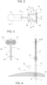
figure 2 is a schematic plan view from the top of an apparatus for energy recovery provided on the boat offigure 1 ; -
figure 3 is a schematic front view of a detail of the apparatus for energy recovery offigure 2 ; -
figure 4 shows a detail offigure 1 , on a larger scale and with more details; and -
figures 5 to 10 are similar tofigures 1 and4 and show a sequence of movements of a blade that is part of the apparatus for energy recovery. - In
figure 1 , reference number 1 is used to indicate, as a whole, a boat. - The boat has a
hull 2 extending longitudinally along an axis X, which coincides with the normal sailing direction of the boat. - In addition, the
hull 2 extends in width and height according to a transverse axis, not shown, and according to an axis Z, which are perpendicular to one another and relative to the axis X, so as to form a (in particular, right-handed) Cartesian coordinate system of orthogonal axes, which is fixed relative to thehull 2. The X axis, the transverse axis and the axis Z are commonly referred to as roll axis, pitch axis and yaw axis, respectively. - The boat 1 preferably comprises a
keel 3, which projects downwards along anaxis 4 starting from aportion 5 of thehull 2, arranged in an intermediate position between the bow and the stern and at the centre between the sides of thehull 2. In particular, theportion 5 is the lowest part of thehull 2. Preferably, theaxis 4 is orthogonal to the axis X. Preferably, thekeel 3 has a lower end that supports or defines abulb 6, having a mass (for example of about 8-10 tons) such as to place the centre of gravity of the boat 1 in a relatively low position, in particular in order to enable a self-righting of the boat 1 even in case of a possible total capsizing. - According to a variant which is not shown herein, the
keel 3 is coupled to thehull 2 at its upper end so as to be able to rotate relative to the Z axis, due to the action of an actuator, about an axis which is parallel to the X axis, in particular to move thebulb 6 to the right or left. - The boat 1 comprises a
blade 10, which is arranged below thehull 2 so as to be permanently and completely immersed in water and has a shape and/or structure and/or dimensions such as to define a hydrodynamic lift and/or a hydrodynamic resistance as a result of a relative speed in relation to the water in which it is immersed. - Preferably, the
blade 10 is supported by thekeel 3 and protrudes with respect to thekeel 3 in a way that is not shown, along anaxis 11 transverse to the axes X and Z. - According to an aspect of the invention, the
blade 10 is mounted on asupport 12, for example defined by a shaft or a rod, sliding together with theblade 10 relative to thekeel 3 and thehull 2 along a trajectory K defined by a guide 13 (schematically shown). For example, the trajectory K is straight and coincides with theaxis 4. Theguide 13 can be part of thekeel 3 or is arranged inside thehull 2. - Preferably, two
blades 10 are provided, on opposite sides of thesupport 12. - According to variants which are not shown herein, the
keel 3 lacks thebulb 6; or theblade 10 is arranged on a keel other than thekeel 3 that supports thebulb 6; or thesupport 12 with theblade 10 projects downwards from thehull 2 without being supported by, or associated with, any keel; and/or thesupport 12 with theblade 10 is arranged in a longitudinal position other than the one shown herein (for example, it can be arranged at the bow). - According to another aspect of the invention, the
blade 10 has an external configuration that can be changed to vary its hydrodynamic lift and/or its hydrodynamic resistance along the trajectory K. The way in which to change the external configuration is not essential and, for example, it can consist of: - changing the angle of inclination of the
entire blade 10 about theaxis 11 relative to the support 12 (and, therefore, relative to thekeel 3, in the case shown herein), and/or - changing the external shape of the
blade 10; this change in shape, in turn, can be obtained by- o deforming flexible walls that define the outer surface of the
blade 10; for example, according to a known technique, this deformation can be caused by moving a cam (not shown) located inside theblade 10, or - o rotating, about the
axis 11, a front or rear end of theblade 10, movable relative to the remaining part, which remains fixed with respect to thesupport 12.
- o deforming flexible walls that define the outer surface of the
- The images shown in the accompanying figures are to be understood as functional diagrams and do not constructively show the specific way in which the external configuration of the
blade 10 is varied. - As schematically shown in
figure 4 , the external configuration of theblade 10 is changed by operating anactuator 14, of the linear or rotary type, preferably powered by electric energy. Theactuator 14 is carried by thesupport 12 and, hence, is movable together with theblade 10 and thesupport 12 along the trajectory K defined by theguide 13. - Preferably, the
actuator 14 and the lower part of thesupport 12 are housed in thekeel 3 and the latter has a lateral slit (not shown), which is parallel to the trajectory K and allows the blade 10 (which is external to the keel 3) and the lower part of the support 12 (which is internal to the keel 3) to be coupled to one another. - If necessary, a transmission, which is not shown, can be provided between the
actuator 14 and theblade 10. In turn, the activation of theactuator 14 is controlled by an electronic control unit 15 (schematically shown), whose functions will be described more in detail below. - The
blade 10, thesupport 12, theactuator 14 and theelectronic control unit 15 are part of anapparatus 16 for energy recovery, which exploits the hydrodynamic lift and/or the hydrodynamic resistance generated by theblade 10 in response to a movement of the boat 1 relative to the water and, therefore, in response to a relative movement between the water and theblade 10. - Specifically, the
apparatus 16 can be configured according to two preferred embodiments, one exploiting the movement of the boat 1 during navigation to generate hydrodynamic lift along the trajectory K and the other exploiting the natural oscillatory pitching movement of the bow of the boat 1, triggered by the wave motion of the sea, to generate hydrodynamic resistance along the trajectory K. Thesupport 12 moves with a reciprocating motion along the direction K due to the effect of the hydrodynamic lift of the blade 10 (as also described below with reference tofigures 5 to 10 ) or due to the effect of the hydrodynamic resistance of theblade 10. - This reciprocating motion can take place, at most, between an upper end-of-stroke position and a lower end-of-stroke position, defined for example by reference elements and/or stop elements that are not shown herein.
- The reciprocating motion actually takes place between a top dead centre and a bottom dead centre, which could coincide with the aforementioned end-of-stroke positions.
- With reference to
figures 1 and2 , theapparatus 16 further comprises at least oneelectric generator 18. Thegenerator 18 comprises arotor 19, which can rotate about an axis R. Thegenerator 18 is configured to convert a kinetic energy associated with a rotation of the rotor 19 (in fact, the kinetic energy of the rotation of the rotor 19) into electric energy. - The electric energy produced by the
generator 18 can be stored in a power storage device, on board the boat 1, such as a battery (not shown), used to power the electric utilities of the boat 1. - The
rotor 19 is coupled to thesupport 12 by means of atransmission mechanism 20 so as to rotate in response to the translation of thesupport 12. - In other words, the
mechanism 20 transforms the reciprocating translatory motion of thesupport 12 along the trajectory K into a corresponding rotation of therotor 19 about the axis R, in particular a continuous rotation according to a single direction of rotation, for example clockwise or counterclockwise. - In other words, thanks to the
mechanism 20, a first translation of thesupport 12, followed by a second translation of thesupport 12 in the opposite direction relative to the first translation, causes, as a whole, a rotation, for example clockwise or counterclockwise, of therotor 19 according to the single direction of rotation, namely without the latter changing with the shift from the first translation to the second translation. - In this sense, the term "continuous" refers precisely to the absence of a reversal of the direction of rotation of the
rotor 19 due to the reversal of the direction of translation of thesupport 12 shifting from the first translation to the second translation. Therefore, the term "continuous" should not be understood in the restrictive sense that the angular speed of therotor 19 cannot in any case be zero at one or more moments of time. - With reference to
figure 2 , preferably, themechanism 20 comprises twotransmissions rotor 19. - The
transmissions support 12 into rotary motions and then selectively transmit such rotary motions so as to cause therotor 19 to rotate about the axis R according to the single rotation direction. In other words, when thetransmission 21 converts the first translation into a rotary motion and transmits the latter to therotor 19, thetransmission 22 does not transmit any rotation torque to therotor 19; vice versa, when thetransmission 22 converts the second translation into a rotary motion and transmits the latter to therotor 19, thetransmission 21 does not transmit any rotation torque to therotor 19. - More in detail, the
transmissions respective decoupling devices rotor 19 from the translation of thesupport 12 and/or to interrupt the respective couplings between therotor 19 and thesupport 12. - Each one of the
decoupling devices - an automatic decoupling device, such as a freewheel device, or
- a clutch device, for example a tooth coupling or a friction clutch, operated by an actuator (not shown) that is controlled by the
control unit 15 so as to engage and disengage thecorresponding device - It could be advantageous to also take into consideration a speed threshold below which the
devices rotor 19 from being slowed down by a slowing down of thesupport 12, when, instead, thesame rotor 19 could have an inertia that is sufficient to rotate faster. - In case of disengagement, the coupling between the
rotor 19 and thesupport 12 is interrupted. On the other hand, when thedevice control unit 15, the coupling is restored. - As mentioned above, the
control unit 15 controls the activation of the clutch device as a function of one or more quantities corresponding to or indicative of the direction of translation and, preferably, of the speed of translation of thesupport 12. These quantities are acquired by thecontrol unit 15 by means of dedicated transducers (not shown) configured to detect the quantities. - According to the specific embodiment shown in
figures 3 and 4 , thetransmissions respective racks support 12, meshing withrespective pinions - Therefore, the
pinions support 12. - With reference to
figure 2 , preferably, thetransmissions toothed wheels pinions corresponding devices pinions respective devices wheels pinions - The
wheels toothed wheel 31, which operates therotor 19 of thegenerator 18. In particular, thewheel 31 is coaxial and fixed relative to therotor 19. - The
devices rotor 19 when thepinions - Therefore, thanks to the
devices wheels wheel 31 and to the fact that thepinions wheel 31 and, hence, therotor 19 can only rotate by means of a single one of thetransmissions - As a matter of fact, the
devices wheels wheels support 12. - When they are decoupled from the
support 12, thewheels wheel 31. - The
mechanism 20 schematically represented infigure 3 is one of the possible mechanisms conceivable for transforming the reciprocating translatory motion of thesupport 12 into a rotation of therotor 19 according to a single rotation direction. For instance, themechanism 20 could for example comprise a typical connecting rod-crank mechanism, whose properties are well known and do not need to be described in detail. - According to a variant that is not show herein, the
mechanism 20 comprises one single transmission (for example defined by thepinion 27 or 28), which converts the translatory motion of thesupport 12 into a rotary motion and transfers the latter to therotor 19, which, hence, rotates with a reciprocating rotary motion about the axis R (without a decoupling device interposed between therotor 19 and the support 12): suitable electric/electronic devices are then provided to process and store the generated electric energy (which has an oscillating intensity and also reaches zero values at the top and bottom dead centres of the translation of the blade 10). - According to a different embodiment, the
generator 18, of the rotary type, is replaced by a generator of electric energy of the linear type, for example by a linear alternator: in this case, themechanism 20 could be absent, namely said generator could be directly coupled to thesupport 12. - The
apparatus 16 of the boat 1 works as follows, with reference tofigures 5 to 10 , where the boat 1 is navigating, for example due to the thrust of the wind (sailing). - Starting from
figure 5 , at the bottom dead centre of the translation stroke of thesupport 12, the external configuration of theblade 10 defines a hydrodynamic airfoil that is set/adjusted by operating theactuator 14, so as to have a first hydrodynamic lift directed upwards, namely towards thehull 2, due to the effect of the relative movement between theairfoil 10 and the water along the navigation direction. - This first hydrodynamic lift corresponds to a thrust that causes the
blade 10 to translate along the trajectory K towards the hull 2 (figure 6 ) until it reaches the top dead centre (figure 7 ). - At the latter (
figure 8 ), the external configuration (i.e. the airfoil) of theblade 10 is automatically changed by the control unit 15: the latter operates theactuator 14 so as to reverse the direction of thrust of the hydrodynamic lift, namely so as to have a second hydrodynamic lift directed in the opposite direction relative to the hull 2 (always considering the hydrodynamic effects caused by the movement along the navigation direction). - Therefore, the
blade 10 reverses the direction of translation, as the hydrodynamic thrust is now directed downwards (figure 9 ). When theblade 10 reaches the bottom dead centre (figure 10 ), theactuator 14 is automatically actuated by thecontrol unit 15 to reverse again the direction in which the hydrodynamic lift is directed and, hence, obtain again a hydrodynamic lift and a translation facing upwards along the direction K. - It is evident that the automatic switching of the external configuration of the blade 10 (namely, the automatic reversal of the direction in which the hydrodynamic lift is directed) occurs in response to the attainment of the top and bottom dead centres.
- In this embodiment, where the movement of the boat 1 in the navigation direction is exploited (possibly in combination with ocean currents), the top and bottom dead centres are located along the trajectory K in respective positions that are predefined and fixed (if necessary, adjustable during the initial setting of the
apparatus 16, but anyway stable after said initial setting). In particular, the top and bottom dead centres respectively correspond to the end-of-travel positions provided for the translation, so as to take advantage of the maximum stroke available in each one of the two directions of translation. - In particular, the
control unit 15 is connected to suitable sensors, for example proximity sensors or position sensors (not shown), for these two positions, to detect the reaching of the top and bottom dead centres by thesupport 12 and/or theblade 10 and then supply corresponding consent signals to thecontrol unit 15. The latter controls theactuator 14 in response to said consent signals, namely exactly when the blade and thesupport 12 have reached the top and bottom dead centres. - As mentioned above, according to another embodiment, it is possible to exploit the natural pitching movement of the boat 1 in order to cause a translation of the
blade 10 and of thesupport 12 relative to thehull 2. In this case, the external configuration of theblade 10 is set/adjusted by thecontrol unit 15 through theactuator 14 at the top and bottom dead centres so as to have a first and a second hydrodynamic resistance, which are directed along the trajectory K in directions contrary to the lifting and to the lowering, respectively, of the boat 1, namely in counter-phase with respect to the pitching movement. In other words, when the wave motion causes a lifting of thehull 2, a first hydrodynamic resistance of theblade 10 is set so as to holdblade 10 down, whereby thesupport 12 slides in theguide 13 which, in the meantime, is rising together with thehull 2; similarly, when the wave motion causes a lowering of thehull 2, the external configuration of theblade 10 is reversed, namely a second hydrodynamic resistance is set so as to hold theblade 10 up, whereby thesupport 12 slides in the opposite direction in theguide 13, which, in the meantime, is lowering itself together with thehull 2. - Preferably, though not necessarily, the
control unit 15 is configured so as to have, as its objective or target, maintaining theblade 10 in the vicinity of a fixed depth with respect to the free surface of the water, while thehull 2 pitches naturally. - In this case, the top and bottom dead centres, where the switching of the external configuration of the
blade 10 must take place, are not located in fixed positions, but depend on the actual range of thehull 2 during the pitching (and, hence, on the extent of the wave motion). In other words, the top dead centre and the bottom dead centre of the translation of theblade 10 and of thesupport 12 correspond to the bottom dead centre and to the top dead centre, respectively, of the oscillation of thehull 2 during pitching. - To this regard, the
electronic control unit 15 is configured so as to synchronize the activation of theactuator 14 and, hence, the switching of the external configuration of theblade 10 with the pitching oscillation motion of thehull 2. In particular, thecontrol unit 15 is connected to suitable sensors, for example inertial sensors or IMUs (not shown), located on thehull 2 and configured so as to detect the angle of orientation of thehull 2 about the transverse pitch axis. Thecontrol unit 15 receives the signals emitted by these sensors and is configured so as to - determine the top and bottom dead centres of the oscillation of the
hull 2 based on the measurements carried out, - control the
actuator 15 at the top and bottom dead centres that were determined. - The result is similar to the one described above with reference to
figures 5 to 10 for the previous embodiment, although the external shape and/or the inclination of theblade 10 are preferably different from the ones shown in said figures, to guarantee the desired hydrodynamic resistance along the trajectory K. - The generation of electric energy in the
generator 18 causes a mechanical resistance that counters the translation of the support 12: the dimensions and shapes in the various configurations of theblade 10 are established by design so as to guarantee a sufficient hydrodynamic lift (when exploiting the navigation of the boat 1) or a sufficient hydrodynamic resistance (when exploiting the pitch of the hull 2) to overcome the mechanical resistance exerted by thegenerator 18 during the production of electric energy (in addition to overcoming the resistance caused by frictions in the coupling to theguide 13, frictions and inertias of themechanism 20, inertia of therotor 19, etc.). - Owing to the above, the advantages of the
apparatus 16 mounted on the boat 1 are evident. - Thanks to the
blade 10 immersed in the water and thanks to normal movements that are typical of the boat 1 (navigation or pitching), the simple use of the boat 1 allows for the generation of an alternative movement of theblade 10 and of thesupport 12, which, in turn, can be exploited to generate electric energy through thegenerator 18. - The electric energy can be directly used to power the electric utilities of the boat 1 or stored in one or more electric energy storage devices, such as batteries, capacitors and the like.
- Other advantages are then obtained through the detailed features described above.
- Finally, the boat 1 disclosed above with reference to the accompanying figures can be subject to changes and variants, which, though, do not go beyond the scope of protection defined by the appended claims.
- In particular, as mentioned above, the external shape of the
blade 10 and the dimensional proportions relative to the other components of the boat 1 can be different from the ones schematically shown herein by way of non-limiting example. - Furthermore, at least in principle, the
support 12 could be provided with a rotary motion, instead of having translatory motion, so that the trajectory K could be curved, instead of being straight. - Finally, a system could be provided to retract the
blade 10 and the lower part of thesupport 12, to bring them out of the water (for example into the hull 2), when thegenerator 18 is not in use.
Claims (10)
- Boat (1) comprising:- a hull (2),- an apparatus (16) for electric energy recovery, the apparatus comprising an electric generator (18);characterised in that said apparatus (16) further comprises:- a support (12) movable with respect to said hull (2) with a reciprocating motion along a trajectory (K), and coupled to said electric generator (18) so as to generate electric energy due to the displacement of the support (12) between a top dead center and a lower dead center along said trajectory (K);- a blade (10) carried by said support (12) and arranged below said hull (2) so as to be permanently and completely arranged in the water during the use of said electric generator (18);- actuator means (14) operable to vary an external configuration of said blade (10) so as to set a hydrodynamic lift and/or a hydrodynamic resistance defined by said blade (10) along said trajectory (K);- an electronic control unit (15) configured to operate said actuators (14) and change said hydrodynamic lift and/or said hydrodynamic resistance when said support (12) and said blade (10) reach said top dead centre and said bottom dead centre.
- The boat according to claim 1, wherein said trajectory (K) is rectilinear.
- The boat according to claim 1 or 2, wherein said apparatus (16) comprises a guide (13), which is arranged in a fixed position relative to said hull (2), defines said trajectory (K) and is engaged by said support (12) in a sliding manner.
- The boat according to claim 3, wherein said electric generator (18) comprises a rotor (19), and wherein said apparatus (16) comprises a transmission mechanism (20), which couples said support (12) to said rotor (19) and is configured to convert the reciprocating translatory motion of said support (12) into a rotary motion for said rotor (19) .
- The boat according to claim 4, wherein said transmission mechanism (20) comprises a first and a second transmission (21,22), which are arranged in parallel between said support (12) and said rotor (19), are configured, each, so as to convert the reciprocating translatory motion of said support (12) into a rotary motion for said rotor (19), and comprise respective decoupling devices (23, 24) for transmitting rotational torque to said rotor (19) only in one of the two rotation directions.
- The boat according to claim 5, wherein said decoupling devices (23, 24) are defined by freewheeling devices or by clutch devices controllable to be selectively disengaged depending on the translation direction of said support (12).
- The boat according to any one of the preceding claims, wherein said top and lower dead centers are arranged in fixed positions along said trajectory (K); and wherein said actuator means (14) are operated so as to set a first and a second hydrodynamic lift, which are opposed to each other and tend to push said blade (10) along said trajectory (K) downwards and, respectively, upwards when said hull (2) is under navigation.
- The boat according to claim 7, wherein said apparatus (16) further comprises sensor means connected to said electronic control unit (15) and configured to detect the attainment of said fixed positions by said support (12) and/or said blade (10); said electronic control unit (15) being configured to operate said actuator means (14) in response to detections of said sensor means.
- The boat according to any one of claims 1 to 6, wherein said top and lower dead centers of said support (12) correspond, respectively, to a lower dead center and a top dead center of said hull (2) during an oscillatory pitching movement of said hull (2); and wherein said actuator means (14) are operated in such a way to set a first and a second hydrodynamic resistance which are opposed to each other and tend to hold said blade (10) along said trajectory (K) downwardly and, respectively, upwardly when said hull (2) raises and, respectively, lowers during pitching.
- The boat according to claim 9, wherein said apparatus (16) further comprises sensor means connected to said electronic control unit (15) and configured to detect a pitch angle of said hull (2), said electronic control unit (15) being configured to operate said actuator means (14) in response to detections of said sensor means.
Applications Claiming Priority (1)
| Application Number | Priority Date | Filing Date | Title |
|---|---|---|---|
| IT202300017688 | 2023-08-29 |
Publications (1)
| Publication Number | Publication Date |
|---|---|
| EP4516665A1 true EP4516665A1 (en) | 2025-03-05 |
Family
ID=88505163
Family Applications (2)
| Application Number | Title | Priority Date | Filing Date |
|---|---|---|---|
| EP24195805.7A Pending EP4516664A1 (en) | 2023-08-29 | 2024-08-22 | Boat with an energy recovering apparatus |
| EP24195822.2A Pending EP4516665A1 (en) | 2023-08-29 | 2024-08-22 | Boat with an energy recovering apparatus |
Family Applications Before (1)
| Application Number | Title | Priority Date | Filing Date |
|---|---|---|---|
| EP24195805.7A Pending EP4516664A1 (en) | 2023-08-29 | 2024-08-22 | Boat with an energy recovering apparatus |
Country Status (2)
| Country | Link |
|---|---|
| EP (2) | EP4516664A1 (en) |
| WO (1) | WO2025046406A1 (en) |
Citations (4)
| Publication number | Priority date | Publication date | Assignee | Title |
|---|---|---|---|---|
| NO326942B1 (en) * | 2007-06-29 | 2009-03-16 | Oyvind Resch | Offshore power plant |
| WO2012000025A1 (en) * | 2010-06-29 | 2012-01-05 | William Darcy John Monaghan | Submerged waterwheel for oceanic power |
| US8100650B2 (en) * | 2006-07-10 | 2012-01-24 | Atargis Energy Corporation | Cyclical wave energy converter |
| US20120187694A1 (en) * | 2009-09-23 | 2012-07-26 | Engervik Technology As | Converting Kinetic Energy Using a Hydrofoil |
-
2024
- 2024-08-22 EP EP24195805.7A patent/EP4516664A1/en active Pending
- 2024-08-22 EP EP24195822.2A patent/EP4516665A1/en active Pending
- 2024-08-22 WO PCT/IB2024/058160 patent/WO2025046406A1/en active Pending
Patent Citations (4)
| Publication number | Priority date | Publication date | Assignee | Title |
|---|---|---|---|---|
| US8100650B2 (en) * | 2006-07-10 | 2012-01-24 | Atargis Energy Corporation | Cyclical wave energy converter |
| NO326942B1 (en) * | 2007-06-29 | 2009-03-16 | Oyvind Resch | Offshore power plant |
| US20120187694A1 (en) * | 2009-09-23 | 2012-07-26 | Engervik Technology As | Converting Kinetic Energy Using a Hydrofoil |
| WO2012000025A1 (en) * | 2010-06-29 | 2012-01-05 | William Darcy John Monaghan | Submerged waterwheel for oceanic power |
Also Published As
| Publication number | Publication date |
|---|---|
| WO2025046406A1 (en) | 2025-03-06 |
| EP4516664A1 (en) | 2025-03-05 |
Similar Documents
| Publication | Publication Date | Title |
|---|---|---|
| EP2222550B1 (en) | A fin propulsion apparatus | |
| CA2771341C (en) | Wave action electric generating system | |
| CN101519113B (en) | Wave energy-based gliding propeller | |
| CN203362387U (en) | Device for converting wave-motion power | |
| EP2500561A2 (en) | Propulsion or motor device for converting energy into power, using the forces generated by the surface movement of a liquid or fluid or the like | |
| US7525214B2 (en) | Wave-power system and method for generating energy at constant rotational speed at variable significant wave heights and periods | |
| CN102164816B (en) | Apparatus for oscillating a foil in a fluid, related boat and device | |
| EP3334925B1 (en) | A wave energy convertor | |
| JP2020536781A (en) | Azimuth thrusters, ships, floating platforms, submarines and submarines | |
| NO317623B1 (en) | System for utilizing sinusoidal motion samples | |
| CN101513927A (en) | Tilt rotor vector propeller based on wave energy | |
| JPH05164036A (en) | Barge type platform for wave activated power generation | |
| EP2162616B1 (en) | Sea wave energy converter | |
| EP4516665A1 (en) | Boat with an energy recovering apparatus | |
| GB2410299A (en) | An ocean power converter | |
| JP2013525670A (en) | A system for generating energy from ocean waves | |
| EP3233621B1 (en) | A watercraft | |
| EP2007980B1 (en) | Arrangement for recovering energy | |
| KR101542877B1 (en) | Automatic flexural reciprocating device of oscillating tidal stream generators | |
| CN101549749A (en) | Automatic thrashing and propelling mechanism used for steamship and motor-driven boat | |
| WO2025172515A2 (en) | Apparatus for generating energy from water waves, watercraft and sails | |
| WO2025208175A1 (en) | Oscillating mass engine assembly | |
| WO2024176073A1 (en) | Energy conversion plant |
Legal Events
| Date | Code | Title | Description |
|---|---|---|---|
| PUAI | Public reference made under article 153(3) epc to a published international application that has entered the european phase |
Free format text: ORIGINAL CODE: 0009012 |
|
| STAA | Information on the status of an ep patent application or granted ep patent |
Free format text: STATUS: THE APPLICATION HAS BEEN PUBLISHED |
|
| AK | Designated contracting states |
Kind code of ref document: A1 Designated state(s): AL AT BE BG CH CY CZ DE DK EE ES FI FR GB GR HR HU IE IS IT LI LT LU LV MC ME MK MT NL NO PL PT RO RS SE SI SK SM TR |
|
| STAA | Information on the status of an ep patent application or granted ep patent |
Free format text: STATUS: REQUEST FOR EXAMINATION WAS MADE |
|
| 17P | Request for examination filed |
Effective date: 20250901 |