EP4516663A1 - Boat with an energy recovery apparatus from boat motion - Google Patents
Boat with an energy recovery apparatus from boat motion Download PDFInfo
- Publication number
- EP4516663A1 EP4516663A1 EP24195537.6A EP24195537A EP4516663A1 EP 4516663 A1 EP4516663 A1 EP 4516663A1 EP 24195537 A EP24195537 A EP 24195537A EP 4516663 A1 EP4516663 A1 EP 4516663A1
- Authority
- EP
- European Patent Office
- Prior art keywords
- rotor
- rotation
- slide
- axis
- boat
- Prior art date
- Legal status (The legal status is an assumption and is not a legal conclusion. Google has not performed a legal analysis and makes no representation as to the accuracy of the status listed.)
- Pending
Links
Images



Classifications
-
- B—PERFORMING OPERATIONS; TRANSPORTING
- B63—SHIPS OR OTHER WATERBORNE VESSELS; RELATED EQUIPMENT
- B63J—AUXILIARIES ON VESSELS
- B63J3/00—Driving of auxiliaries
- B63J3/04—Driving of auxiliaries from power plant other than propulsion power plant
-
- F—MECHANICAL ENGINEERING; LIGHTING; HEATING; WEAPONS; BLASTING
- F03—MACHINES OR ENGINES FOR LIQUIDS; WIND, SPRING, OR WEIGHT MOTORS; PRODUCING MECHANICAL POWER OR A REACTIVE PROPULSIVE THRUST, NOT OTHERWISE PROVIDED FOR
- F03B—MACHINES OR ENGINES FOR LIQUIDS
- F03B13/00—Adaptations of machines or engines for special use; Combinations of machines or engines with driving or driven apparatus; Power stations or aggregates
- F03B13/12—Adaptations of machines or engines for special use; Combinations of machines or engines with driving or driven apparatus; Power stations or aggregates characterised by using wave or tide energy
- F03B13/14—Adaptations of machines or engines for special use; Combinations of machines or engines with driving or driven apparatus; Power stations or aggregates characterised by using wave or tide energy using wave energy
- F03B13/16—Adaptations of machines or engines for special use; Combinations of machines or engines with driving or driven apparatus; Power stations or aggregates characterised by using wave or tide energy using wave energy using the relative movement between a wave-operated member, i.e. a "wom" and another member, i.e. a reaction member or "rem"
- F03B13/20—Adaptations of machines or engines for special use; Combinations of machines or engines with driving or driven apparatus; Power stations or aggregates characterised by using wave or tide energy using wave energy using the relative movement between a wave-operated member, i.e. a "wom" and another member, i.e. a reaction member or "rem" wherein both members, i.e. wom and rem are movable relative to the sea bed or shore
-
- B—PERFORMING OPERATIONS; TRANSPORTING
- B63—SHIPS OR OTHER WATERBORNE VESSELS; RELATED EQUIPMENT
- B63B—SHIPS OR OTHER WATERBORNE VESSELS; EQUIPMENT FOR SHIPPING
- B63B35/00—Vessels or similar floating structures specially adapted for specific purposes and not otherwise provided for
- B63B2035/009—Wind propelled vessels comprising arrangements, installations or devices specially adapted therefor, other than wind propulsion arrangements, installations, or devices, such as sails, running rigging, or the like, and other than sailboards or the like or related equipment
-
- B—PERFORMING OPERATIONS; TRANSPORTING
- B63—SHIPS OR OTHER WATERBORNE VESSELS; RELATED EQUIPMENT
- B63J—AUXILIARIES ON VESSELS
- B63J3/00—Driving of auxiliaries
- B63J2003/001—Driving of auxiliaries characterised by type of power supply, or power transmission, e.g. by using electric power or steam
- B63J2003/002—Driving of auxiliaries characterised by type of power supply, or power transmission, e.g. by using electric power or steam by using electric power
Definitions
- the invention relates to a boat, in particular a sailing boat, more in particular a racing boat.
- Some racing boats are provided with a plurality of energy-consuming devices, such as an engine, hydraulic actuators, charging devices for charging batteries and the like.
- these devices are powered by energy produced by an internal combustion engine on board the boat.
- the engine in turn, is powered by fossil fuels.
- This aspect leads to some drawbacks, including the emission of pollutants produced by the combustion of fossil fuel and the sizing of the devices closely related to the amount of fuel on board the boat.
- An object of the invention is to fulfil at least one of the needs discussed above.
- reference number 1 is used to indicate, as a whole, a boat.
- the boat has a hull 2 extending longitudinally along an axis X, which coincides with the normal sailing direction of the boat.
- the hull extends in width and height according to axes Y, Z, respectively, which are perpendicular to one another and relative to the axis X, with which they form a Cartesian coordinate system of orthogonal axes, in particular a right-handed one.
- the coordinate system is fixed relative to the hull 2, whereby the axes X, Y, Z define the body axes of the hull 2, also commonly referred to as roll axis, pitch axis and yaw axis, respectively.
- the boat 1 comprises a mass 3, which is suspended relative to the hull 2, namely movable relative to it with at least one or more degrees of freedom.
- the mass 3 is located at a longitudinal end (i.e. according to the axis X) of the boat 1, for example at the bow. More specifically, by dividing the length of the boat 1 into three equal parts along the axis X, the mass 3 is located in the area of the last third towards the bow of the boat 1. This is not in any case limiting, so that the mass 3 could still be placed differently along the hull 2.
- the boat 1 comprises a mechanism 4, which, in turn, comprises a kinematic chain 5, which couples the mass 3 to the hull 2, while enabling a relative movement of the mass 3 relative to the hull 2.
- the mass 3 is suspended relative to the hull by the kinematic chain 5.
- the mechanism 4 is coupled to the hull 2 and comprises the mass 3.
- the kinematic chain 5 comprises at least one slide or carriage 6 having a translatory degree of freedom along a straight axis K.
- the mass 3 could be fixed relative to the slide 6 (as, for example, in the embodiments of figures 2 and 5 ), although not necessarily; in fact, the mass 3 could also be more generally coupled to the slide 6 (as, for example, in the embodiment of figure 6 ), so that a relative movement of the mass 3 relative to the hull 2 is in any case transmitted to the slide 6.
- the kinematic chain 5 comprises two link elements, one of them being the slide 6 and the other one being a member having at least a guiding function for guiding or forcing the slide 6 to move along the axis K.
- the link elements are coupled to one another by means of a coupling conceptually defining a prismatic joint P, i.e. a joint that enables the translatory degree of freedom of one of the link elements relative to the other link element.
- the other link element could conceptually be a screw 7, whereby the slide 6 comprises or is defined by a nut screw.
- the screw 7 and the slide 6 define a nut-screw coupling or system.
- the coupling that defines the prismatic joint P is a nut-screw coupling or system.
- the screw 7 and the slide 6 are part of a ball screw.
- the ball screw comprises rolling bodies between the screw 7 and the slide 6, so that the coupling between the screw 7 and the slide 6 takes place indirectly by means of the rolling bodies, which are in contact with both the screw 7 and the slide 6 in respective diametrically opposite points.
- the nut-screw coupling implies that the translation of the slide 6 along the axis K corresponds to a rotation of the screw 7 around its own axis, in this case coinciding with the axis K.
- the screw 7 defines, more in general, a member rotatable around its own axis and coupled to the slide 6 so as to rotate around its axis according to opposite directions of rotation (clockwise and counterclockwise) respectively when the slide 6 translates according to opposite directions along the axis K, namely in response to translations of the slide 6 according to opposite directions along the axis K.
- the boat 1 further comprises at least one electric motor-generator 8.
- the motor-generator 8 comprises a rotor 9 rotatable around a rotor axis R.
- the motor-generator 8 is configured to convert a kinetic energy associated with a rotation of the rotor 9 (actually, the kinetic energy of the rotation of the rotor 9) into electrical energy.
- the electrical energy produced by the motor-generator 8 can be stored in a power storage device of the boat 1, such as a battery, or also be directly used to power the electric utilities of the boat 1.
- the rotor 9 is coupled to the slide 6 so as to rotate in response to the translation of the slide 6.
- the boat 1 or the mechanism 4 comprises a further mechanism or sub-mechanism 10, the coupling between the screw 7 (or, more in general, the aforementioned rotatable member) and the slide 6 being part thereof.
- the mechanism 10 is configured to transform a reciprocating translatory motion of the slide 6 along the axis K into a corresponding rotation, in particular a continuous rotation, of the rotor 9 around the axis R according to one single direction of rotation, for example clockwise or counterclockwise.
- a first translation of the slide 6, followed by a second translation of the slide 6 in the opposite direction relative to the first translation causes, as a whole, a rotation, for example clockwise or counterclockwise, of the rotor 9 according to the single direction of rotation, i.e. without the latter changing with the shift from the first translation to the second translation.
- the term “continuous” refers precisely to the absence of a reversal of the direction of rotation of the rotor 9 due to the reversal of the direction of translation of the slide 6 shifting from the first translation to the second translation. Therefore, the term “continuous” should not be understood, in particular, in the restrictive sense that the angular speed of the rotor 9 cannot in any case be zero at one or more moments in time.
- the rotor 9 is coupled to the slide 6 through the mechanism 10.
- Figure 3 shows a particular example of a portion of the mechanism 10.
- the mechanism 10 comprises the screw 7 or, more in general, the rotatable member and two transmissions 11, 12 arranged in parallel and respectively configured to transmit the rotations of the screw 7 to the rotor 9.
- the transmissions 11, 12 are configured to couple the rotatable member (or the screw 7) to the rotor by respectively transmitting rotations of the rotatable member according to the two possible opposite directions of rotation, thereby causing the rotor 9 to rotate around the rotor axis R according to said single direction of rotation of the rotor 9 in response to both rotations of the rotatable member according to the two opposite directions of rotation thereof.
- the transmission 11 is configured so that a rotation of the screw 7 (or, more in general, of the rotatable member) according to a first direction of rotation is transmitted to the rotor 9 as a rotation of the latter around the axis R according to the single direction of rotation.
- the transmission 11 is configured to cause the rotor 9 to rotate according to the single direction of rotation in response to the rotation of the screw 7 (or, more in general, of the rotatable member) according to the first direction of rotation.
- the transmission 12 is configured so that a rotation of the screw 7 (or, more in general, of the rotatable member) according to a second direction of rotation contrary to the first direction of rotation is transmitted to the rotor 9 as a rotation of the latter around the axis R according to the single direction of rotation.
- the transmission 12 is configured to cause the rotor 9 to rotate according to the single direction of rotation in response to the rotation of the screw 7 (or, more in general, of the rotatable member) according to the second direction of rotation.
- the transmissions 11, 12 comprise respective decoupling devices 13, 14 respectively configured to decouple the rotor 9 from the screw 7 (or, more in general, from the rotatable member) by means of the respective transmissions 11, 12 when the screw 7 rotates according to the second and the first direction of rotation.
- the decoupling devices 13, 14 are configured to interrupt the respective couplings between the rotor 9 and the screw 7 (or, more in general, the rotatable member) by means of the respective transmissions 11, 12, respectively, when the screw 7 (or, more in general, the rotatable member) rotates according to the second and the first direction of rotation.
- the decoupling device 13 is configured to decouple the rotor 9 from the screw 7 through the transmission 11, namely to interrupt the coupling created by the transmission 11 between the rotor 9 and the screw 7 (while the rotor 9 and the screw 7 can remain coupled through the transmission 12), when the screw 7 rotates according to the second direction of rotation.
- the decoupling device 14 is configured to decouple the rotor 9 from the screw 7 through the transmission 12, namely to interrupt the coupling created by the transmission 12 between the rotor 9 and the screw 7 (while the rotor 9 and the screw 7 can remain coupled through the transmission 11), when the screw 7 rotates according to the first direction of rotation.
- Each one of the decoupling devices 13, 14, independently of the other one, could be or comprise a device with an automatic decoupling function, such as a free wheel, or an engagement device, for example a tooth engagement or a clutch engagement, controllable to be selectively engaged or disengaged as a function of the rotation of the screw 7 (or, more in general, of the rotatable member).
- an automatic decoupling function such as a free wheel
- an engagement device for example a tooth engagement or a clutch engagement
- the engagement device could be engaged only when the angular speed of the screw 7 or the corresponding translation speed of the slide 6 exceeds a predetermined threshold, namely the engagement device would thus be disengaged whenever the angular speed of the screw 7 or the corresponding translation speed of the slide 6 is equal to or less than the threshold.
- the engagement devices of the decoupling devices 13, 14 can respectively be engaged only when the screw 7 rotates according to the first and the second direction, respectively.
- the boat 1 can comprise a control unit (not shown) for controlling the engagement device as a function of one or more quantities corresponding to or indicative of the angular speed of the screw 7 or the speed of translation of the slide 6.
- the quantities can be acquired by the control unit through special transducers configured to detect the quantities.
- the mechanism 10 comprises a rack 15 coupled to the screw 7 so as to translate according to opposite directions in response to the rotations according to opposite directions of the screw 7.
- the mechanism 10 can comprise a pinion 16 fixed to the screw 7 and configured to couple the screw 7 to the rack 15.
- the pinion 16 specifically meshes with the rack 15.
- the transmissions 11, 12 comprise respective gear wheels 17, 18, which mesh with the rack 15 on two opposite sides of the rack 15, so that the gear wheels 17, 18 rotate in opposite directions.
- the transmissions 11, 12 comprise two further gear wheels 19, 20, which are arranged downstream of the respective decoupling devices 13, 14 and rotate in the same direction as the wheels 17, 18, respectively, when coupled to the latter by means of the decoupling devices 13, 14.
- the wheels 19, 20 both mesh with a gear wheel 21 of the motor-generator 8 forming two external gears; the gear wheel 21 is fixed relative to the rotor 9.
- the decoupling devices 13, 14 are both configured to decouple the rotor 9 from the screw 7 by means of the respective transmissions 11, 12, respectively, when the wheels 17, 18 rotate according to a same specific direction of rotation, for example clockwise or counterclockwise.
- the decoupling devices 13, 14 decouple the wheels 19, 20 from the wheels 17, 18, respectively.
- the wheel 21 and, hence, the rotor 9 can only rotate by means of a single one of the transmissions 11, 12 and according to one single direction of rotation, precisely equal to the aforementioned specific direction.
- the decoupling devices 13, 14 allow only one of the respective wheels 19, 20 to rotate and only in the direction contrary to the aforementioned specific direction.
- the wheel 17 would be decoupled from the wheel 19 by means of the decoupling device 13, while the wheel 18 could remain coupled to the wheel 20 by means of the decoupling device 14, since the wheel 18 would rotate in the opposite direction relative to the specific direction, i.e. contrary to the wheel 17.
- the wheel 19 would remain idle while the wheel 20 would rotate in the opposite direction to the specific direction, i.e. in the same direction as the wheel 18.
- the external meshing between the wheels 20, 21 then causes the wheel 21 to rotate, therefore, in the specific direction.
- the wheel 18 would be decoupled from the wheel 20 by means of the decoupling device 14, while the wheel 17 could remain coupled to the wheel 19 by means of the decoupling device 13, since the wheel 17 would rotate in the opposite direction relative to the specific direction, i.e. contrary to the wheel 18.
- the wheel 20 would remain idle while the wheel 19 would rotate in the opposite direction to the specific direction, i.e. in the same direction as the wheel 17.
- the external meshing between the wheels 20, 21 then causes the wheel 21 to still rotate in the specific direction.
- the mechanism 10 schematically shown in figure 3 is one of the possible specific mechanisms conceivable for transforming a reciprocating translatory motion of the slide 6 into a rotation of the rotor 9 according to a single rotation direction.
- the mechanism 10 could for example comprise a typical connecting rod-crank mechanism, whose properties are well known and do not need to be described in detail.
- the axis K is fixed relative to the hull 2.
- the screw 7 or, more in general, the rotatable member is supported by the hull 2 in a rotary manner around its own axis, specifically coinciding with the axis K, for example by means of support elements 23, such as bearings.
- the support elements 23 could include two radial bearings and an axial bearing or two oblique rolling bearings mounted in an X- or O-shaped configuration.
- the axis K is parallel to one between the axis X and the axis Y, specifically the axis Y.
- the axis K is parallel to the axis Z.
- the slide 6 or the mass 3 is suspended against the action of the force of gravity by means of an elastic element 24, in particular a spring. Specifically, the slide 6 is suspended relative to the hull 2 by means of the elastic element 24.
- the slide 6 or the mass 3 could also be suspended by means of a shock absorber, in addition or alternatively to the elastic element 24.
- elastic elements and/or shock absorbers can widely be used to couple the slide 6 or the mass 3 to any other component of the boat 1, relative to which the slide 6 or the mass 3 is movable.
- the other component could be chosen from those described herein or could be any other component that may not be described in detail.
- the coupling of the slide 6 or the mass 3 to another component by means of an elastic element and/or a shock absorber implies the existence of an elastic and/or damping reaction applied to the slide 6 or the mass 3, which affects the dynamics of the slide 6 or the mass 3 relative to the hull 2.
- the mechanism 4 comprises a plurality of kinematic chains 5 having respective slides 6, each having a degree of translatory freedom along the corresponding axis K.
- the slides 6 are coupled to respective rotors 9 of corresponding electric motor-generators 8 of the boat 1, for example in ways already described above and, therefore, not repeated any further for the sake of brevity.
- figure 6 shows three kinematic chains 5, in which the relative slides 6 are respectively coupled to the mass 3 by means of ball joints 30, for example forming part of the mechanism 4.
- the kinematic chains 5 in figure 6 are all the same, although arranged differently from one another relative to the mass 3 and the hull 2.
- the kinematic chain 5 comprises a guiding member, which carries the relative slide 6 and extends parallel to the corresponding axis K (the direction along which the guiding member extends could also coincide with the axis K).
- the guiding member and the slide 6 are part of the two link elements already mentioned above, which are coupled to one another by means of the prismatic joint P.
- the guiding member could be or comprise the screw 7 or, more generally, the rotatable member described above.
- the guiding member is coupled to the hull 2 by means of a ball joint 31, for example forming part of the mechanism 4.
- the slide 6 as well as the mechanism 10 and even the motor-generator 8 (the latter being coupled to the slide 6 through the mechanism 10) can oscillate or, anyway, move relative to the hull 2.
- the kinematic chain 5, as shown in the specific non-limiting embodiment of figure 6 includes the ball joints 30, 31 as well as the prismatic joint P defining the coupling between the slide 6 and the guiding member.
- the kinematic chain 5 has no other joints.
- the kinematic chain 5 comprises or is defined by an arm extendible along the axis, wherein the extendible arm has a base portion, defined by the guiding member, and a portion actually extendible along the axis K relative to the base portion.
- the actually extendible portion is defined by the slide 6.
- the extendible arm has two ends respectively coupled to the mass 3 and to the hull 2 by means of the ball joints 30, 31.
- the kinematic chain 5 is one of the three serial branches (the other two being defined by the other two kinematic chains 5) of the mechanism 4, which has a parallel kinematic configuration, where the mass 3 constitutes the platform shared by the three branches.
- branches could also be available in a number other than three and could not necessarily be all the same, as long as the mechanism 4 remains suitable for suspending the mass 3 and comprises the slide 6.
- the boat 1 is provided with one or more non-shown "foils”, i.e. plates or wings that are fixed or movable relative to the hull 2 and are designed to convert the resistance to advancement offered by water into a bearing load on the hull 2.
- the bearing load allows the hull 2 to be lifted beyond the free surface of the water, so that the hull 2 can substantially glide above the water surface with the support of the "foils".
- the hull 2 moves relative to the suspended mass 3, so that there is a relative motion, which, in the ideal case, could be of a periodic oscillatory nature, between the hull 2 and the mass 3.
- the relative motion corresponds to a translatory motion of the slide 6 along the axis K.
- the translatory motion corresponds to the component along the axis K of the relative motion.
- the translatory motion can be of a periodic reciprocating type. In particular, this depends on the orientation of the axis K and on the operating conditions of the boat 1.
- the slide 6 would have the reciprocating translatory motion, which would thus follow the periodicity of the periodic oscillatory component.
- the relative motion is not ideally periodic, but can still be represented in a frequency domain as a composition of several harmonic contributions.
- the movement of the slide 6 relative to the hull 2 is still representable in a frequency domain, as well as in a time domain, and therefore has a spectrum in the frequency domain.
- the translatory motion of the slide 6 can generally be of a reciprocating type, even if not ideally periodic.
- the mechanism 10 transfers the reciprocating motion of the slide 6 to the rotor 9, which is caused to rotate around the rotor axis R with a single direction of rotation.
- the rotation of the rotor 9 could be continuous, despite the reciprocating motion of the slide 6.
- the motor-generator 8 can generate electrical energy through the rotation of the rotor 9, in particular in a continuous manner.
- the generation of electrical energy corresponds to a torque that counters the rotation of the rotor 9; said torque is clearly transmitted to the slide 6 and to the mass 3, thereby countering the movement of the slide 6.
- the torque countering the rotation of the rotor 9 can be limited, in general, to a maximum torque for various reasons, for example due to the size of the motor-generator 8 or on the basis of a control of the motor-generator 8 based on the actual energy needs of the boat 1.
- the mass 3 is sufficiently large (namely, its value, for example expressed in kg), so that its inertia ensures that the slide 6, in particular for all the operating conditions of the boat 1, translates along the axis K overcoming the resistance of the frictions of the coupling to the guiding member, the frictions and inertias of the mechanism 10, the inertia of the rotor 9 and the maximum torque.
- the mass 3 is sufficiently large to guarantee the dynamic balance of the rotor 9 under the action of the maximum torque contrary to the rotation of the rotor 9, in particular for all the operating conditions of the boat 1.
- the angular speed of the rotor 9 is sufficient to ensure the generation of electrical energy by the motor-generator 8.
- the simple use of the boat 1 can enable the generation of electrical energy through the motor-generator 8.
- the electrical energy can directly be used to power the electrical utilities of the boat 1 or stored in one or more electrical energy storage devices, such as batteries, capacitors and the like.
- the coupling with the prismatic joint P is particularly simple and effective, as well as enabling a solid construction of the mechanism 10 and the possibility of safely supporting the motor-generator 8.
- boat 1 according to the invention can be subject to changes and variants, which, though, do not go beyond the scope of protection set forth in the appended claims.
Landscapes
- Engineering & Computer Science (AREA)
- Chemical & Material Sciences (AREA)
- Combustion & Propulsion (AREA)
- Mechanical Engineering (AREA)
- General Engineering & Computer Science (AREA)
- Ocean & Marine Engineering (AREA)
- Transmission Devices (AREA)
Abstract
A boat (1) includes a hull (2), a first mechanism (4) coupled to the hull (2) and comprising a mass (3) suspended relative to the hull (2) by at least one kinematic chain (5) comprising at least one slide (6) with a translatory degree of freedom along a first straight axis (K), an electric motor-generator (8), which comprises a rotor (9) rotating about a rotor axis (R) and is configured to convert a kinetic energy of a rotation of the rotor (9) into electrical energy, and a second mechanism (10) configured to transform a reciprocating translatory motion of the slide (6) along the first straight axis (K) into a corresponding rotation of the rotor (9) around the rotor axis (R) according to a single direction of rotation.
Description
- This patent application claims priority from
Italian patent application no. 102023000017685 filed on August 29, 2023 - The invention relates to a boat, in particular a sailing boat, more in particular a racing boat.
- Some racing boats are provided with a plurality of energy-consuming devices, such as an engine, hydraulic actuators, charging devices for charging batteries and the like.
- Usually, these devices are powered by energy produced by an internal combustion engine on board the boat.
- The engine, in turn, is powered by fossil fuels.
- This aspect leads to some drawbacks, including the emission of pollutants produced by the combustion of fossil fuel and the sizing of the devices closely related to the amount of fuel on board the boat.
- Therefore, the aforementioned drawbacks need to be eliminated, preferably in a simple and reliable fashion.
- More specifically, there is a need to identify alternative energy sources, without the emission of combustion products.
- An object of the invention is to fulfil at least one of the needs discussed above.
- Said object is reached by a boat as defined in
claim 1. - The dependent claims define special embodiments of the invention.
- Hereinafter, an embodiment of the invention will be described, in order to allow the latter to be better understood, by way of non-limiting example and with reference to the accompanying drawings, wherein:
-
figure 1 is a side view of a boat according to the invention, -
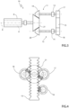
figure 2 is a schematic view of an energy recovery assembly of the boat, according to an embodiment, -
figure 3 is a diagram of a transmission assembly belonging to the energy recovery assembly, -
figure 4 is a front view of the transmission assembly offigure 3 , and -
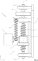
figures 5 ,6 are diagrams of the energy recovery assembly, according to further embodiments. - In
figure 1 ,reference number 1 is used to indicate, as a whole, a boat. - The boat has a
hull 2 extending longitudinally along an axis X, which coincides with the normal sailing direction of the boat. - In addition, the hull extends in width and height according to axes Y, Z, respectively, which are perpendicular to one another and relative to the axis X, with which they form a Cartesian coordinate system of orthogonal axes, in particular a right-handed one.
- The coordinate system is fixed relative to the
hull 2, whereby the axes X, Y, Z define the body axes of thehull 2, also commonly referred to as roll axis, pitch axis and yaw axis, respectively. - The
boat 1 comprises amass 3, which is suspended relative to thehull 2, namely movable relative to it with at least one or more degrees of freedom. - Preferably, the
mass 3 is located at a longitudinal end (i.e. according to the axis X) of theboat 1, for example at the bow. More specifically, by dividing the length of theboat 1 into three equal parts along the axis X, themass 3 is located in the area of the last third towards the bow of theboat 1. This is not in any case limiting, so that themass 3 could still be placed differently along thehull 2. - In order to suspend the
mass 3, theboat 1 comprises amechanism 4, which, in turn, comprises akinematic chain 5, which couples themass 3 to thehull 2, while enabling a relative movement of themass 3 relative to thehull 2. - Therefore, the
mass 3 is suspended relative to the hull by thekinematic chain 5. - The
mechanism 4 is coupled to thehull 2 and comprises themass 3. - The
kinematic chain 5 comprises at least one slide orcarriage 6 having a translatory degree of freedom along a straight axis K. - The
mass 3 could be fixed relative to the slide 6 (as, for example, in the embodiments offigures 2 and5 ), although not necessarily; in fact, themass 3 could also be more generally coupled to the slide 6 (as, for example, in the embodiment offigure 6 ), so that a relative movement of themass 3 relative to thehull 2 is in any case transmitted to theslide 6. - More in detail, the
kinematic chain 5 comprises two link elements, one of them being theslide 6 and the other one being a member having at least a guiding function for guiding or forcing theslide 6 to move along the axis K. - The link elements are coupled to one another by means of a coupling conceptually defining a prismatic joint P, i.e. a joint that enables the translatory degree of freedom of one of the link elements relative to the other link element.
- For example, the other link element could conceptually be a
screw 7, whereby theslide 6 comprises or is defined by a nut screw. - Therefore, the
screw 7 and theslide 6 define a nut-screw coupling or system. In other words, the coupling that defines the prismatic joint P is a nut-screw coupling or system. Conveniently, thescrew 7 and theslide 6 are part of a ball screw. The ball screw comprises rolling bodies between thescrew 7 and theslide 6, so that the coupling between thescrew 7 and theslide 6 takes place indirectly by means of the rolling bodies, which are in contact with both thescrew 7 and theslide 6 in respective diametrically opposite points. - The nut-screw coupling implies that the translation of the
slide 6 along the axis K corresponds to a rotation of thescrew 7 around its own axis, in this case coinciding with the axis K. - The
screw 7 defines, more in general, a member rotatable around its own axis and coupled to theslide 6 so as to rotate around its axis according to opposite directions of rotation (clockwise and counterclockwise) respectively when theslide 6 translates according to opposite directions along the axis K, namely in response to translations of theslide 6 according to opposite directions along the axis K. - In fact, many known mechanisms can be considered as an alternative to the coupling between the
screw 7 and theslide 6, whereby the translations of theslide 6 in the two possible opposite directions respectively cause the rotation of a generic member rotatable around its own axis according to opposite directions of rotation. - The
boat 1 further comprises at least one electric motor-generator 8. The motor-generator 8 comprises a rotor 9 rotatable around a rotor axis R. The motor-generator 8 is configured to convert a kinetic energy associated with a rotation of the rotor 9 (actually, the kinetic energy of the rotation of the rotor 9) into electrical energy. - The electrical energy produced by the motor-
generator 8 can be stored in a power storage device of theboat 1, such as a battery, or also be directly used to power the electric utilities of theboat 1. - The rotor 9 is coupled to the
slide 6 so as to rotate in response to the translation of theslide 6. - More in detail, the
boat 1 or themechanism 4 comprises a further mechanism orsub-mechanism 10, the coupling between the screw 7 (or, more in general, the aforementioned rotatable member) and theslide 6 being part thereof. Themechanism 10 is configured to transform a reciprocating translatory motion of theslide 6 along the axis K into a corresponding rotation, in particular a continuous rotation, of the rotor 9 around the axis R according to one single direction of rotation, for example clockwise or counterclockwise. - In other words, thanks to the
mechanism 10, a first translation of theslide 6, followed by a second translation of theslide 6 in the opposite direction relative to the first translation, causes, as a whole, a rotation, for example clockwise or counterclockwise, of the rotor 9 according to the single direction of rotation, i.e. without the latter changing with the shift from the first translation to the second translation. - Therefore, using still other words, the
mechanism 10 is configured to transform translations of theslide 6 according to opposite directions along the axis K into a corresponding rotation, for example clockwise or counterclockwise, of the rotor 9 according to the single direction of rotation, i.e. without the latter changing with the shift between the translations. - In this sense, the term "continuous" refers precisely to the absence of a reversal of the direction of rotation of the rotor 9 due to the reversal of the direction of translation of the
slide 6 shifting from the first translation to the second translation. Therefore, the term "continuous" should not be understood, in particular, in the restrictive sense that the angular speed of the rotor 9 cannot in any case be zero at one or more moments in time. - Hence, the rotor 9 is coupled to the
slide 6 through themechanism 10. -
Figure 3 shows a particular example of a portion of themechanism 10. - The
mechanism 10 comprises thescrew 7 or, more in general, the rotatable member and twotransmissions screw 7 to the rotor 9. - The
transmissions - In other words, the
transmission 11 is configured so that a rotation of the screw 7 (or, more in general, of the rotatable member) according to a first direction of rotation is transmitted to the rotor 9 as a rotation of the latter around the axis R according to the single direction of rotation. Hence, thetransmission 11 is configured to cause the rotor 9 to rotate according to the single direction of rotation in response to the rotation of the screw 7 (or, more in general, of the rotatable member) according to the first direction of rotation. - Furthermore, the
transmission 12 is configured so that a rotation of the screw 7 (or, more in general, of the rotatable member) according to a second direction of rotation contrary to the first direction of rotation is transmitted to the rotor 9 as a rotation of the latter around the axis R according to the single direction of rotation. Hence, thetransmission 12 is configured to cause the rotor 9 to rotate according to the single direction of rotation in response to the rotation of the screw 7 (or, more in general, of the rotatable member) according to the second direction of rotation. - More in detail, the
transmissions respective decoupling devices respective transmissions screw 7 rotates according to the second and the first direction of rotation. - Therefore, the
decoupling devices respective transmissions - In other words, the
decoupling device 13 is configured to decouple the rotor 9 from thescrew 7 through thetransmission 11, namely to interrupt the coupling created by thetransmission 11 between the rotor 9 and the screw 7 (while the rotor 9 and thescrew 7 can remain coupled through the transmission 12), when thescrew 7 rotates according to the second direction of rotation. - On the other hand, the
decoupling device 14 is configured to decouple the rotor 9 from thescrew 7 through thetransmission 12, namely to interrupt the coupling created by thetransmission 12 between the rotor 9 and the screw 7 (while the rotor 9 and thescrew 7 can remain coupled through the transmission 11), when thescrew 7 rotates according to the first direction of rotation. - Each one of the
decoupling devices - For example, the engagement device could be engaged only when the angular speed of the
screw 7 or the corresponding translation speed of theslide 6 exceeds a predetermined threshold, namely the engagement device would thus be disengaged whenever the angular speed of thescrew 7 or the corresponding translation speed of theslide 6 is equal to or less than the threshold. - When the engagement device is disengaged, the coupling between the rotor 9 and the
screw 7 through the corresponding one of thetransmissions - This could be advantageous as it would prevent the rotor 9 from being slowed down, for example, by a slowing down of the
slide 6, when, instead, the rotor 9 could have had sufficient inertia to rotate faster than it would have rotated if coupled to theslide 6. - Clearly, the engagement devices of the
decoupling devices screw 7 rotates according to the first and the second direction, respectively. - The
boat 1 can comprise a control unit (not shown) for controlling the engagement device as a function of one or more quantities corresponding to or indicative of the angular speed of thescrew 7 or the speed of translation of theslide 6. The quantities can be acquired by the control unit through special transducers configured to detect the quantities. - According to the specific non-limiting embodiment of
figure 3 , themechanism 10 comprises arack 15 coupled to thescrew 7 so as to translate according to opposite directions in response to the rotations according to opposite directions of thescrew 7. - For example, the
mechanism 10 can comprise apinion 16 fixed to thescrew 7 and configured to couple thescrew 7 to therack 15. Thepinion 16 specifically meshes with therack 15. - The
transmissions respective gear wheels rack 15 on two opposite sides of therack 15, so that thegear wheels - The
transmissions further gear wheels respective decoupling devices wheels decoupling devices - The
wheels gear wheel 21 of the motor-generator 8 forming two external gears; thegear wheel 21 is fixed relative to the rotor 9. - The
decoupling devices screw 7 by means of therespective transmissions wheels - More precisely, in order to perform their function, the
decoupling devices wheels wheels - Therefore, thanks to the
decoupling devices wheels wheel 21 and to the fact that thewheels wheel 21 and, hence, the rotor 9 can only rotate by means of a single one of thetransmissions - Indeed, the
decoupling devices respective wheels - More precisely, for example, if the
wheel 17 were to rotate in the specific direction, it would be decoupled from thewheel 19 by means of thedecoupling device 13, while thewheel 18 could remain coupled to thewheel 20 by means of thedecoupling device 14, since thewheel 18 would rotate in the opposite direction relative to the specific direction, i.e. contrary to thewheel 17. - By so doing, the
wheel 19 would remain idle while thewheel 20 would rotate in the opposite direction to the specific direction, i.e. in the same direction as thewheel 18. The external meshing between thewheels wheel 21 to rotate, therefore, in the specific direction. - Similarly, if the
wheel 18 were to rotate in the specific direction, it would be decoupled from thewheel 20 by means of thedecoupling device 14, while thewheel 17 could remain coupled to thewheel 19 by means of thedecoupling device 13, since thewheel 17 would rotate in the opposite direction relative to the specific direction, i.e. contrary to thewheel 18. - By so doing, the
wheel 20 would remain idle while thewheel 19 would rotate in the opposite direction to the specific direction, i.e. in the same direction as thewheel 17. The external meshing between thewheels wheel 21 to still rotate in the specific direction. - The
mechanism 10 schematically shown infigure 3 is one of the possible specific mechanisms conceivable for transforming a reciprocating translatory motion of theslide 6 into a rotation of the rotor 9 according to a single rotation direction. For instance, themechanism 10 could for example comprise a typical connecting rod-crank mechanism, whose properties are well known and do not need to be described in detail. - According to the embodiments of
figures 2 and5 , the axis K is fixed relative to thehull 2. - In particular, the
screw 7 or, more in general, the rotatable member is supported by thehull 2 in a rotary manner around its own axis, specifically coinciding with the axis K, for example by means ofsupport elements 23, such as bearings. - For example, the
support elements 23 could include two radial bearings and an axial bearing or two oblique rolling bearings mounted in an X- or O-shaped configuration. - More in particular, in
figure 2 , the axis K is parallel to one between the axis X and the axis Y, specifically the axis Y. - In the specific example of
figure 5 , the axis K is parallel to the axis Z. - In
figure 5 , theslide 6 or themass 3 is suspended against the action of the force of gravity by means of anelastic element 24, in particular a spring. Specifically, theslide 6 is suspended relative to thehull 2 by means of theelastic element 24. - Furthermore, the
slide 6 or themass 3 could also be suspended by means of a shock absorber, in addition or alternatively to theelastic element 24. - In general, elastic elements and/or shock absorbers can widely be used to couple the
slide 6 or themass 3 to any other component of theboat 1, relative to which theslide 6 or themass 3 is movable. - The other component could be chosen from those described herein or could be any other component that may not be described in detail.
- Furthermore, the use of the elastic and/or shock-absorbing elements, in the ways just described above, can be considered in all the forms of implementation of this description or even more in general.
- The coupling of the
slide 6 or themass 3 to another component by means of an elastic element and/or a shock absorber implies the existence of an elastic and/or damping reaction applied to theslide 6 or themass 3, which affects the dynamics of theslide 6 or themass 3 relative to thehull 2. - According to the embodiment of
figure 6 , themechanism 4 comprises a plurality ofkinematic chains 5 havingrespective slides 6, each having a degree of translatory freedom along the corresponding axis K. - The
slides 6 are coupled to respective rotors 9 of corresponding electric motor-generators 8 of theboat 1, for example in ways already described above and, therefore, not repeated any further for the sake of brevity. - Indeed, the coupling of the
slides 6 to the corresponding rotors 9 can take place by means ofrespective mechanisms 10, such as themechanism 10 already described above. - In particular,
figure 6 shows threekinematic chains 5, in which the relative slides 6 are respectively coupled to themass 3 by means of ball joints 30, for example forming part of themechanism 4. - The
kinematic chains 5 infigure 6 are all the same, although arranged differently from one another relative to themass 3 and thehull 2. - Therefore, only one of the
kinematic chains 5 offigure 6 will be described, since features thereof specifically disclosed below can also apply to the otherkinematic chains 5 or, more in general, to any otherkinematic chain 5, such as those according to the embodiments offigures 2 and5 . - The
kinematic chain 5 comprises a guiding member, which carries therelative slide 6 and extends parallel to the corresponding axis K (the direction along which the guiding member extends could also coincide with the axis K). - The guiding member and the
slide 6 are part of the two link elements already mentioned above, which are coupled to one another by means of the prismatic joint P. - Therefore, the guiding member could be or comprise the
screw 7 or, more generally, the rotatable member described above. - In particular, the guiding member is coupled to the
hull 2 by means of a ball joint 31, for example forming part of themechanism 4. - Therefore, the
slide 6 as well as themechanism 10 and even the motor-generator 8 (the latter being coupled to theslide 6 through the mechanism 10) can oscillate or, anyway, move relative to thehull 2. - The
kinematic chain 5, as shown in the specific non-limiting embodiment offigure 6 , includes the ball joints 30, 31 as well as the prismatic joint P defining the coupling between theslide 6 and the guiding member. - More specifically, although not necessarily, the
kinematic chain 5 has no other joints. - In practice, the
kinematic chain 5 comprises or is defined by an arm extendible along the axis, wherein the extendible arm has a base portion, defined by the guiding member, and a portion actually extendible along the axis K relative to the base portion. The actually extendible portion is defined by theslide 6. In particular, the extendible arm has two ends respectively coupled to themass 3 and to thehull 2 by means of the ball joints 30, 31. - In the specific example of
figure 6 , thekinematic chain 5 is one of the three serial branches (the other two being defined by the other two kinematic chains 5) of themechanism 4, which has a parallel kinematic configuration, where themass 3 constitutes the platform shared by the three branches. - Alternatively, the branches could also be available in a number other than three and could not necessarily be all the same, as long as the
mechanism 4 remains suitable for suspending themass 3 and comprises theslide 6. - In general, an example of the operation of the
boat 1 is the following. - More specifically, the
boat 1 is provided with one or more non-shown "foils", i.e. plates or wings that are fixed or movable relative to thehull 2 and are designed to convert the resistance to advancement offered by water into a bearing load on thehull 2. The bearing load allows thehull 2 to be lifted beyond the free surface of the water, so that thehull 2 can substantially glide above the water surface with the support of the "foils". - Even when the
hull 2 completely or almost emerges, thehull 2 is still subject to a plurality of differently oriented forces (for example, along the axes X, Y, Z). - These forces could have, at least in an ideal case, a module with a periodic trend over time with relatively low frequencies.
- Thanks to these forces, the
hull 2 moves relative to the suspendedmass 3, so that there is a relative motion, which, in the ideal case, could be of a periodic oscillatory nature, between thehull 2 and themass 3. - In general, the relative motion corresponds to a translatory motion of the
slide 6 along the axis K. Precisely, the translatory motion corresponds to the component along the axis K of the relative motion. - In the case of a periodic oscillatory nature of the relative motion, the translatory motion can be of a periodic reciprocating type. In particular, this depends on the orientation of the axis K and on the operating conditions of the
boat 1. - If the axis K were aligned with a periodic oscillatory component of the relative motion, then the
slide 6 would have the reciprocating translatory motion, which would thus follow the periodicity of the periodic oscillatory component. - More in general, in a real case, the relative motion is not ideally periodic, but can still be represented in a frequency domain as a composition of several harmonic contributions.
- Therefore, the movement of the
slide 6 relative to thehull 2 is still representable in a frequency domain, as well as in a time domain, and therefore has a spectrum in the frequency domain. - However, the translatory motion of the
slide 6 can generally be of a reciprocating type, even if not ideally periodic. - The
mechanism 10 transfers the reciprocating motion of theslide 6 to the rotor 9, which is caused to rotate around the rotor axis R with a single direction of rotation. In particular, the rotation of the rotor 9 could be continuous, despite the reciprocating motion of theslide 6. - Hence, the motor-
generator 8 can generate electrical energy through the rotation of the rotor 9, in particular in a continuous manner. - The generation of electrical energy corresponds to a torque that counters the rotation of the rotor 9; said torque is clearly transmitted to the
slide 6 and to themass 3, thereby countering the movement of theslide 6. - The torque countering the rotation of the rotor 9 can be limited, in general, to a maximum torque for various reasons, for example due to the size of the motor-
generator 8 or on the basis of a control of the motor-generator 8 based on the actual energy needs of theboat 1. - Preferably, the
mass 3 is sufficiently large (namely, its value, for example expressed in kg), so that its inertia ensures that theslide 6, in particular for all the operating conditions of theboat 1, translates along the axis K overcoming the resistance of the frictions of the coupling to the guiding member, the frictions and inertias of themechanism 10, the inertia of the rotor 9 and the maximum torque. - In other words, preferably, the
mass 3 is sufficiently large to guarantee the dynamic balance of the rotor 9 under the action of the maximum torque contrary to the rotation of the rotor 9, in particular for all the operating conditions of theboat 1. - In the aforesaid dynamic balance, the angular speed of the rotor 9 is sufficient to ensure the generation of electrical energy by the motor-
generator 8. - Owing to the above, the advantages of the
boat 1 are evident. - Indeed, thanks to the suspension of the
mass 3 through themechanism 4 and thanks to themechanism 10, the simple use of theboat 1 can enable the generation of electrical energy through the motor-generator 8. - The electrical energy can directly be used to power the electrical utilities of the
boat 1 or stored in one or more electrical energy storage devices, such as batteries, capacitors and the like. - The coupling with the prismatic joint P is particularly simple and effective, as well as enabling a solid construction of the
mechanism 10 and the possibility of safely supporting the motor-generator 8. - Finally, the
boat 1 according to the invention can be subject to changes and variants, which, though, do not go beyond the scope of protection set forth in the appended claims. - In particular, one or more of the various embodiments described and shown herein can be combined with one another or even be simply used together in the
same boat 1.
Claims (7)
- Boat (1) comprising- a hull (2),- a first mechanism (4) coupled to the hull (2) and comprising a mass (3) suspended relative to the hull (2) by at least one kinematic chain (5) comprising at least one slide (6) having a translatory degree of freedom along a first straight axis (K),- an electric motor-generator (8), which comprises a rotor (9) rotating about a rotor axis (R) and is configured to convert a kinetic energy of a rotation of the rotor (9) into electrical energy, and- a second mechanism (10) configured to transform a reciprocating translatory motion of the slide (6) along the first straight axis (K) into a corresponding rotation of the rotor (9) around the rotor axis (R) according to a single direction of rotation.
- The boat according to claim 1, wherein the first straight axis (K) is fixed relative to the hull (2).
- The boat according to claim 1, wherein the kinematic chain (5) comprises a guiding member (7) extending parallel to the first straight axis (K), carrying the slide (6) movably along the first straight axis (K), and coupled to the hull (2) via a ball joint (31).
- The boat according to any one of the preceding claims, wherein the second mechanism (10) comprises- a member (7) rotatable about a second axis and coupled to the slide (6) so as to rotate about the second axis according to opposite directions of rotation respectively in response to translations of the slide (6) according to opposite directions along the first straight axis (K),- two transmissions (11, 12) arranged in parallel and configured to couple the rotatable member (7) to the rotor (9) respectively by transmitting rotations of the rotatable member (7) according to said opposite directions of rotation to the rotor (9), thereby bringing the rotor (9) into rotation about the rotor axis (R) according to said single direction of rotation in response to both rotations of the rotatable member (7) according to said opposite directions of rotation.
- The boat according to claim 4, wherein the transmissions (11, 12) comprise respective decoupling devices (13, 14) configured to interrupt the respective couplings between the rotor (9) and the rotatable member (7) via the respective transmissions (11, 12) respectively when the rotatable member (7) rotates according to a second direction and a first direction respectively defined by said opposite directions of rotation.
- The boat according to claim 5, wherein at least one of the decoupling devices (13, 14) comprises a free wheel or an engagement means controllable to be selectively disengaged as a function of the rotation of the rotatable member to interrupt the relative coupling between the rotor (9) and the rotatable member (7).
- The boat according to any one of claims 4 to 6, wherein the rotatable member (7) and the slide (6) are part of a nut-screw system, such as a ball screw.
Applications Claiming Priority (1)
| Application Number | Priority Date | Filing Date | Title |
|---|---|---|---|
| IT102023000017685A IT202300017685A1 (en) | 2023-08-29 | 2023-08-29 | VESSEL WITH A DEVICE FOR RECOVERING ENERGY FROM THE MOTION OF THE VESSEL |
Publications (1)
| Publication Number | Publication Date |
|---|---|
| EP4516663A1 true EP4516663A1 (en) | 2025-03-05 |
Family
ID=88505487
Family Applications (1)
| Application Number | Title | Priority Date | Filing Date |
|---|---|---|---|
| EP24195537.6A Pending EP4516663A1 (en) | 2023-08-29 | 2024-08-21 | Boat with an energy recovery apparatus from boat motion |
Country Status (4)
| Country | Link |
|---|---|
| EP (1) | EP4516663A1 (en) |
| AU (1) | AU2024331225A1 (en) |
| IT (1) | IT202300017685A1 (en) |
| WO (1) | WO2025046397A1 (en) |
Citations (4)
| Publication number | Priority date | Publication date | Assignee | Title |
|---|---|---|---|---|
| US3774048A (en) * | 1972-02-22 | 1973-11-20 | D Hardingham | Energy generating and storing assembly for marine structure |
| US4256971A (en) * | 1979-11-16 | 1981-03-17 | Rodney Griffith | Wave and wind motion energy transducer |
| DE3340981A1 (en) * | 1982-11-12 | 1984-05-17 | John P. 92026 Escondido Calif. Marken | DEVICE FOR CONVERTING THE STAMPING AND SLINGING MOVEMENTS OF A FLOATING SHIP BODY INTO ELECTRICAL ENERGY |
| US20070084394A1 (en) * | 2005-10-19 | 2007-04-19 | Peter Gudmundson | Power generation in watercraft |
-
2023
- 2023-08-29 IT IT102023000017685A patent/IT202300017685A1/en unknown
-
2024
- 2024-08-21 WO PCT/IB2024/058114 patent/WO2025046397A1/en active Pending
- 2024-08-21 EP EP24195537.6A patent/EP4516663A1/en active Pending
- 2024-08-21 AU AU2024331225A patent/AU2024331225A1/en active Pending
Patent Citations (4)
| Publication number | Priority date | Publication date | Assignee | Title |
|---|---|---|---|---|
| US3774048A (en) * | 1972-02-22 | 1973-11-20 | D Hardingham | Energy generating and storing assembly for marine structure |
| US4256971A (en) * | 1979-11-16 | 1981-03-17 | Rodney Griffith | Wave and wind motion energy transducer |
| DE3340981A1 (en) * | 1982-11-12 | 1984-05-17 | John P. 92026 Escondido Calif. Marken | DEVICE FOR CONVERTING THE STAMPING AND SLINGING MOVEMENTS OF A FLOATING SHIP BODY INTO ELECTRICAL ENERGY |
| US20070084394A1 (en) * | 2005-10-19 | 2007-04-19 | Peter Gudmundson | Power generation in watercraft |
Non-Patent Citations (1)
| Title |
|---|
| GUIZZI GIUSEPPE LEO ET AL: "Preliminary study on a kinetic energy recovery system for sailing yachts", RENEWABLE ENERGY, vol. 62, 27 July 2013 (2013-07-27), pages 216 - 225, XP028740406, ISSN: 0960-1481, DOI: 10.1016/J.RENENE.2013.06.051 * |
Also Published As
| Publication number | Publication date |
|---|---|
| IT202300017685A1 (en) | 2025-03-01 |
| AU2024331225A1 (en) | 2026-03-12 |
| WO2025046397A1 (en) | 2025-03-06 |
Similar Documents
| Publication | Publication Date | Title |
|---|---|---|
| US8866314B2 (en) | Method for operating a power rotary actuator and a power plant for carrying out said method | |
| KR910000987B1 (en) | Harmonic speed changer | |
| CN104755801B (en) | Gear mechanism, reducer and robot arm | |
| CN106903712B (en) | Two-degree-of-freedom collinear mechanical arm joint based on differential rope transmission | |
| CN104723356B (en) | A Soft Contact Joint Based on Dynamic and Static Blocks | |
| US6899308B2 (en) | Passive gravity-compensating mechanisms | |
| EP4516663A1 (en) | Boat with an energy recovery apparatus from boat motion | |
| CN106678360A (en) | Car, gearbox of car and motor gear-shifting system and unit | |
| CN222609666U (en) | Output assembly of joint module of robot | |
| Hirose et al. | Development of a light weight torque limiting M-Drive actuator for hyper-redundant manipulator Float Arm | |
| Park et al. | Safe joint mechanism based on passive compliance for collision safety | |
| CN101482162B (en) | Forward sleepless transmission device and method | |
| US2984124A (en) | Inertia mass crank transmission | |
| CN102767592A (en) | Engagement type gear reducer with small tooth number difference | |
| CN110319169B (en) | One-way power conversion device and power system having the same | |
| KR101886387B1 (en) | Rotating apparatus capable of rapid accelerating having high torque | |
| CN104791426A (en) | Harmonic gear transmission mechanism | |
| CN210770095U (en) | Novel stepless speed changer | |
| CN102678428A (en) | Movable wave energy absorption and conversion device | |
| CN202646586U (en) | Elastic buffer device | |
| CN201407328Y (en) | Two torque continuously variable transmission | |
| Kapelevich et al. | Self-locking gears: Design and potential applications | |
| CN115447741B (en) | Pitching adjusting device driven by crank-link mechanism for underwater robot | |
| US20110186384A1 (en) | Motor and method of operation | |
| SU1762046A1 (en) | Wave gear |
Legal Events
| Date | Code | Title | Description |
|---|---|---|---|
| PUAI | Public reference made under article 153(3) epc to a published international application that has entered the european phase |
Free format text: ORIGINAL CODE: 0009012 |
|
| STAA | Information on the status of an ep patent application or granted ep patent |
Free format text: STATUS: THE APPLICATION HAS BEEN PUBLISHED |
|
| AK | Designated contracting states |
Kind code of ref document: A1 Designated state(s): AL AT BE BG CH CY CZ DE DK EE ES FI FR GB GR HR HU IE IS IT LI LT LU LV MC ME MK MT NL NO PL PT RO RS SE SI SK SM TR |
|
| STAA | Information on the status of an ep patent application or granted ep patent |
Free format text: STATUS: REQUEST FOR EXAMINATION WAS MADE |
|
| 17P | Request for examination filed |
Effective date: 20250901 |