EP4516614A1 - Vehicle for performing minimal risk maneuver and method of operating the vehicle - Google Patents
Vehicle for performing minimal risk maneuver and method of operating the vehicle Download PDFInfo
- Publication number
- EP4516614A1 EP4516614A1 EP24196918.7A EP24196918A EP4516614A1 EP 4516614 A1 EP4516614 A1 EP 4516614A1 EP 24196918 A EP24196918 A EP 24196918A EP 4516614 A1 EP4516614 A1 EP 4516614A1
- Authority
- EP
- European Patent Office
- Prior art keywords
- shoulder
- stoppable
- vehicle
- risk
- areas
- Prior art date
- Legal status (The legal status is an assumption and is not a legal conclusion. Google has not performed a legal analysis and makes no representation as to the accuracy of the status listed.)
- Pending
Links
Images


Classifications
-
- B—PERFORMING OPERATIONS; TRANSPORTING
- B60—VEHICLES IN GENERAL
- B60W—CONJOINT CONTROL OF VEHICLE SUB-UNITS OF DIFFERENT TYPE OR DIFFERENT FUNCTION; CONTROL SYSTEMS SPECIALLY ADAPTED FOR HYBRID VEHICLES; ROAD VEHICLE DRIVE CONTROL SYSTEMS FOR PURPOSES NOT RELATED TO THE CONTROL OF A PARTICULAR SUB-UNIT
- B60W30/00—Purposes of road vehicle drive control systems not related to the control of a particular sub-unit, e.g. of systems using conjoint control of vehicle sub-units
- B60W30/06—Automatic manoeuvring for parking
-
- B—PERFORMING OPERATIONS; TRANSPORTING
- B60—VEHICLES IN GENERAL
- B60W—CONJOINT CONTROL OF VEHICLE SUB-UNITS OF DIFFERENT TYPE OR DIFFERENT FUNCTION; CONTROL SYSTEMS SPECIALLY ADAPTED FOR HYBRID VEHICLES; ROAD VEHICLE DRIVE CONTROL SYSTEMS FOR PURPOSES NOT RELATED TO THE CONTROL OF A PARTICULAR SUB-UNIT
- B60W60/00—Drive control systems specially adapted for autonomous road vehicles
- B60W60/001—Planning or execution of driving tasks
- B60W60/0015—Planning or execution of driving tasks specially adapted for safety
- B60W60/0018—Planning or execution of driving tasks specially adapted for safety by employing degraded modes, e.g. reducing speed, in response to suboptimal conditions
-
- B—PERFORMING OPERATIONS; TRANSPORTING
- B60—VEHICLES IN GENERAL
- B60W—CONJOINT CONTROL OF VEHICLE SUB-UNITS OF DIFFERENT TYPE OR DIFFERENT FUNCTION; CONTROL SYSTEMS SPECIALLY ADAPTED FOR HYBRID VEHICLES; ROAD VEHICLE DRIVE CONTROL SYSTEMS FOR PURPOSES NOT RELATED TO THE CONTROL OF A PARTICULAR SUB-UNIT
- B60W10/00—Conjoint control of vehicle sub-units of different type or different function
- B60W10/04—Conjoint control of vehicle sub-units of different type or different function including control of propulsion units
-
- B—PERFORMING OPERATIONS; TRANSPORTING
- B60—VEHICLES IN GENERAL
- B60W—CONJOINT CONTROL OF VEHICLE SUB-UNITS OF DIFFERENT TYPE OR DIFFERENT FUNCTION; CONTROL SYSTEMS SPECIALLY ADAPTED FOR HYBRID VEHICLES; ROAD VEHICLE DRIVE CONTROL SYSTEMS FOR PURPOSES NOT RELATED TO THE CONTROL OF A PARTICULAR SUB-UNIT
- B60W10/00—Conjoint control of vehicle sub-units of different type or different function
- B60W10/18—Conjoint control of vehicle sub-units of different type or different function including control of braking systems
-
- B—PERFORMING OPERATIONS; TRANSPORTING
- B60—VEHICLES IN GENERAL
- B60W—CONJOINT CONTROL OF VEHICLE SUB-UNITS OF DIFFERENT TYPE OR DIFFERENT FUNCTION; CONTROL SYSTEMS SPECIALLY ADAPTED FOR HYBRID VEHICLES; ROAD VEHICLE DRIVE CONTROL SYSTEMS FOR PURPOSES NOT RELATED TO THE CONTROL OF A PARTICULAR SUB-UNIT
- B60W10/00—Conjoint control of vehicle sub-units of different type or different function
- B60W10/20—Conjoint control of vehicle sub-units of different type or different function including control of steering systems
-
- B—PERFORMING OPERATIONS; TRANSPORTING
- B60—VEHICLES IN GENERAL
- B60W—CONJOINT CONTROL OF VEHICLE SUB-UNITS OF DIFFERENT TYPE OR DIFFERENT FUNCTION; CONTROL SYSTEMS SPECIALLY ADAPTED FOR HYBRID VEHICLES; ROAD VEHICLE DRIVE CONTROL SYSTEMS FOR PURPOSES NOT RELATED TO THE CONTROL OF A PARTICULAR SUB-UNIT
- B60W30/00—Purposes of road vehicle drive control systems not related to the control of a particular sub-unit, e.g. of systems using conjoint control of vehicle sub-units
- B60W30/08—Active safety systems predicting or avoiding probable or impending collision or attempting to minimise its consequences
- B60W30/095—Predicting travel path or likelihood of collision
- B60W30/0956—Predicting travel path or likelihood of collision the prediction being responsive to traffic or environmental parameters
-
- B—PERFORMING OPERATIONS; TRANSPORTING
- B60—VEHICLES IN GENERAL
- B60W—CONJOINT CONTROL OF VEHICLE SUB-UNITS OF DIFFERENT TYPE OR DIFFERENT FUNCTION; CONTROL SYSTEMS SPECIALLY ADAPTED FOR HYBRID VEHICLES; ROAD VEHICLE DRIVE CONTROL SYSTEMS FOR PURPOSES NOT RELATED TO THE CONTROL OF A PARTICULAR SUB-UNIT
- B60W60/00—Drive control systems specially adapted for autonomous road vehicles
- B60W60/001—Planning or execution of driving tasks
- B60W60/0011—Planning or execution of driving tasks involving control alternatives for a single driving scenario, e.g. planning several paths to avoid obstacles
-
- B—PERFORMING OPERATIONS; TRANSPORTING
- B60—VEHICLES IN GENERAL
- B60W—CONJOINT CONTROL OF VEHICLE SUB-UNITS OF DIFFERENT TYPE OR DIFFERENT FUNCTION; CONTROL SYSTEMS SPECIALLY ADAPTED FOR HYBRID VEHICLES; ROAD VEHICLE DRIVE CONTROL SYSTEMS FOR PURPOSES NOT RELATED TO THE CONTROL OF A PARTICULAR SUB-UNIT
- B60W60/00—Drive control systems specially adapted for autonomous road vehicles
- B60W60/001—Planning or execution of driving tasks
- B60W60/0015—Planning or execution of driving tasks specially adapted for safety
- B60W60/0018—Planning or execution of driving tasks specially adapted for safety by employing degraded modes, e.g. reducing speed, in response to suboptimal conditions
- B60W60/00186—Planning or execution of driving tasks specially adapted for safety by employing degraded modes, e.g. reducing speed, in response to suboptimal conditions related to the vehicle
-
- B—PERFORMING OPERATIONS; TRANSPORTING
- B60—VEHICLES IN GENERAL
- B60W—CONJOINT CONTROL OF VEHICLE SUB-UNITS OF DIFFERENT TYPE OR DIFFERENT FUNCTION; CONTROL SYSTEMS SPECIALLY ADAPTED FOR HYBRID VEHICLES; ROAD VEHICLE DRIVE CONTROL SYSTEMS FOR PURPOSES NOT RELATED TO THE CONTROL OF A PARTICULAR SUB-UNIT
- B60W50/00—Details of control systems for road vehicle drive control not related to the control of a particular sub-unit, e.g. process diagnostic or vehicle driver interfaces
- B60W50/02—Ensuring safety in case of control system failures, e.g. by diagnosing, circumventing or fixing failures
- B60W50/029—Adapting to failures or work around with other constraints, e.g. circumvention by avoiding use of failed parts
- B60W2050/0292—Fail-safe or redundant systems, e.g. limp-home or backup systems
-
- B—PERFORMING OPERATIONS; TRANSPORTING
- B60—VEHICLES IN GENERAL
- B60W—CONJOINT CONTROL OF VEHICLE SUB-UNITS OF DIFFERENT TYPE OR DIFFERENT FUNCTION; CONTROL SYSTEMS SPECIALLY ADAPTED FOR HYBRID VEHICLES; ROAD VEHICLE DRIVE CONTROL SYSTEMS FOR PURPOSES NOT RELATED TO THE CONTROL OF A PARTICULAR SUB-UNIT
- B60W50/00—Details of control systems for road vehicle drive control not related to the control of a particular sub-unit, e.g. process diagnostic or vehicle driver interfaces
- B60W50/02—Ensuring safety in case of control system failures, e.g. by diagnosing, circumventing or fixing failures
- B60W50/029—Adapting to failures or work around with other constraints, e.g. circumvention by avoiding use of failed parts
- B60W2050/0295—Inhibiting action of specific actuators or systems
-
- B—PERFORMING OPERATIONS; TRANSPORTING
- B60—VEHICLES IN GENERAL
- B60W—CONJOINT CONTROL OF VEHICLE SUB-UNITS OF DIFFERENT TYPE OR DIFFERENT FUNCTION; CONTROL SYSTEMS SPECIALLY ADAPTED FOR HYBRID VEHICLES; ROAD VEHICLE DRIVE CONTROL SYSTEMS FOR PURPOSES NOT RELATED TO THE CONTROL OF A PARTICULAR SUB-UNIT
- B60W2420/00—Indexing codes relating to the type of sensors based on the principle of their operation
- B60W2420/40—Photo, light or radio wave sensitive means, e.g. infrared sensors
- B60W2420/403—Image sensing, e.g. optical camera
-
- B—PERFORMING OPERATIONS; TRANSPORTING
- B60—VEHICLES IN GENERAL
- B60W—CONJOINT CONTROL OF VEHICLE SUB-UNITS OF DIFFERENT TYPE OR DIFFERENT FUNCTION; CONTROL SYSTEMS SPECIALLY ADAPTED FOR HYBRID VEHICLES; ROAD VEHICLE DRIVE CONTROL SYSTEMS FOR PURPOSES NOT RELATED TO THE CONTROL OF A PARTICULAR SUB-UNIT
- B60W2420/00—Indexing codes relating to the type of sensors based on the principle of their operation
- B60W2420/40—Photo, light or radio wave sensitive means, e.g. infrared sensors
- B60W2420/408—Radar; Laser, e.g. lidar
-
- B—PERFORMING OPERATIONS; TRANSPORTING
- B60—VEHICLES IN GENERAL
- B60W—CONJOINT CONTROL OF VEHICLE SUB-UNITS OF DIFFERENT TYPE OR DIFFERENT FUNCTION; CONTROL SYSTEMS SPECIALLY ADAPTED FOR HYBRID VEHICLES; ROAD VEHICLE DRIVE CONTROL SYSTEMS FOR PURPOSES NOT RELATED TO THE CONTROL OF A PARTICULAR SUB-UNIT
- B60W2420/00—Indexing codes relating to the type of sensors based on the principle of their operation
- B60W2420/54—Audio sensitive means, e.g. ultrasound
-
- B—PERFORMING OPERATIONS; TRANSPORTING
- B60—VEHICLES IN GENERAL
- B60W—CONJOINT CONTROL OF VEHICLE SUB-UNITS OF DIFFERENT TYPE OR DIFFERENT FUNCTION; CONTROL SYSTEMS SPECIALLY ADAPTED FOR HYBRID VEHICLES; ROAD VEHICLE DRIVE CONTROL SYSTEMS FOR PURPOSES NOT RELATED TO THE CONTROL OF A PARTICULAR SUB-UNIT
- B60W2552/00—Input parameters relating to infrastructure
- B60W2552/10—Number of lanes
-
- B—PERFORMING OPERATIONS; TRANSPORTING
- B60—VEHICLES IN GENERAL
- B60W—CONJOINT CONTROL OF VEHICLE SUB-UNITS OF DIFFERENT TYPE OR DIFFERENT FUNCTION; CONTROL SYSTEMS SPECIALLY ADAPTED FOR HYBRID VEHICLES; ROAD VEHICLE DRIVE CONTROL SYSTEMS FOR PURPOSES NOT RELATED TO THE CONTROL OF A PARTICULAR SUB-UNIT
- B60W2552/00—Input parameters relating to infrastructure
- B60W2552/53—Road markings, e.g. lane marker or crosswalk
-
- B—PERFORMING OPERATIONS; TRANSPORTING
- B60—VEHICLES IN GENERAL
- B60W—CONJOINT CONTROL OF VEHICLE SUB-UNITS OF DIFFERENT TYPE OR DIFFERENT FUNCTION; CONTROL SYSTEMS SPECIALLY ADAPTED FOR HYBRID VEHICLES; ROAD VEHICLE DRIVE CONTROL SYSTEMS FOR PURPOSES NOT RELATED TO THE CONTROL OF A PARTICULAR SUB-UNIT
- B60W2554/00—Input parameters relating to objects
- B60W2554/40—Dynamic objects, e.g. animals, windblown objects
- B60W2554/402—Type
-
- B—PERFORMING OPERATIONS; TRANSPORTING
- B60—VEHICLES IN GENERAL
- B60W—CONJOINT CONTROL OF VEHICLE SUB-UNITS OF DIFFERENT TYPE OR DIFFERENT FUNCTION; CONTROL SYSTEMS SPECIALLY ADAPTED FOR HYBRID VEHICLES; ROAD VEHICLE DRIVE CONTROL SYSTEMS FOR PURPOSES NOT RELATED TO THE CONTROL OF A PARTICULAR SUB-UNIT
- B60W2555/00—Input parameters relating to exterior conditions, not covered by groups B60W2552/00, B60W2554/00
- B60W2555/60—Traffic rules, e.g. speed limits or right of way
-
- B—PERFORMING OPERATIONS; TRANSPORTING
- B60—VEHICLES IN GENERAL
- B60W—CONJOINT CONTROL OF VEHICLE SUB-UNITS OF DIFFERENT TYPE OR DIFFERENT FUNCTION; CONTROL SYSTEMS SPECIALLY ADAPTED FOR HYBRID VEHICLES; ROAD VEHICLE DRIVE CONTROL SYSTEMS FOR PURPOSES NOT RELATED TO THE CONTROL OF A PARTICULAR SUB-UNIT
- B60W60/00—Drive control systems specially adapted for autonomous road vehicles
- B60W60/005—Handover processes
- B60W60/0059—Estimation of the risk associated with autonomous or manual driving, e.g. situation too complex, sensor failure or driver incapacity
-
- B—PERFORMING OPERATIONS; TRANSPORTING
- B60—VEHICLES IN GENERAL
- B60Y—INDEXING SCHEME RELATING TO ASPECTS CROSS-CUTTING VEHICLE TECHNOLOGY
- B60Y2302/00—Responses or measures related to driver conditions
- B60Y2302/05—Leading to automatic stopping of the vehicle
Definitions
- This document relates to a vehicle for performing a minimal risk maneuver and a method of operating the vehicle.
- ADAS advanced driver assistance systems
- ADS Automated Driving System
- errors may occur in the autonomous driving system while a vehicle is performing autonomous driving.
- the vehicle may be placed in a dangerous state.
- various embodiments of this document disclose a vehicle that performs a minimal risk maneuver (MRM) to eliminate (or reduce) risk when a situation in which normal autonomous driving is not possible is detected during autonomous driving, and a method of operating the vehicle.
- MRM minimal risk maneuver
- Various embodiments of this document disclose a method and device for determining a minimal risk maneuver stopping type and a stopping location when a situation in which normal autonomous driving is not possible is detected in a vehicle during autonomous driving.
- Various embodiments of this document disclose a method and device for determining a minimal risk maneuver stopping type and a stopping location based on route complexity and stopping risk when a situation in which normal autonomous driving is not possible is detected in a vehicle during autonomous driving.
- an autonomous vehicle comprises at least one sensor for detecting a surrounding environment of the vehicle and generating surrounding environment information, a processor for generating vehicle state information by monitoring a state of the vehicle, and controlling autonomous driving of the vehicle and a controller for controlling an operation of the vehicle according to control of the processor.
- the processor may determine whether a minimal risk maneuver is needed based on at least one among the surrounding environment information and the vehicle state information during autonomous driving of the vehicle, determine a minimal risk maneuver type and a target point where the vehicle will stop when the minimal risk maneuver is needed, and control the vehicle to stop at the target point based on the determined minimal risk maneuver type and target point.
- the processor may calculate a maximum distance or a maximum time that can be driven in a minimum risk maneuver state, search for stoppable areas that can be reached within the maximum distance or the maximum time, classify the searched stoppable areas into full-shoulder stoppable areas and half-shoulder stoppable areas, calculate at least one among route complexity and stopping risk of each of the full-shoulder stoppable areas, determine whether or not stopping is possible at the full-shoulder stoppable areas based on at least one among the calculated route complexity and stopping risk, and calculate, when stopping is not possible in all of the full-shoulder stoppable areas, at least one among route complexity and stopping risk of each of the half-shoulder stoppable areas, and determine a minimal risk maneuver type and a target point where the vehicle will stop based on at least one among the route complexity and the stopping risk at the half-shoulder stoppable areas.
- the processor may calculate a maximum distance or a maximum time that can be driven in a minimum risk maneuver state, search for stoppable areas that can be reached within the maximum distance or the maximum time, calculate at least one among route complexity and stopping risk at the stoppable area, and determine a minimal risk maneuver type and a target point where the vehicle will stop based on the route complexity and the stopping risk of each of the stoppable areas.
- the processor may search for full-shoulder stoppable areas that can be reached within the maximum distance or the maximum time, calculate route complexity of each of the searched full-shoulder stoppable areas, determine a full-shoulder stoppable area where route complexity is lower than or equal to a preset value and having the lowest value as a target point where the vehicle will stop, and determine a full-shoulder stop as the minimal risk maneuver.
- the processor may search for half-shoulder stoppable areas, when there is no full-shoulder stoppable area where the route complexity is lower than or equal to a preset value, determine a half-shoulder stoppable area where the stopping risk is the lowest as a target point where the vehicle will stop and a half-shoulder stop as the minimal risk maneuver type, when there are half-shoulder stoppable areas where route complexity is lower than the route complexity of the full-shoulder stoppable areas and the stopping risk is lower than a preset risk, and determine an in-lane stop or a straight stop as the minimal risk maneuver type, when there is no half-shoulder stoppable area where the route complexity is lower than the route complexity of the full-shoulder stoppable areas.
- the processor may search for half-shoulder stoppable areas, when there is no full-shoulder stoppable area where the route complexity is lower than or equal to a preset value, determine a half-shoulder stoppable area where the stopping risk is the lowest as a target point where the vehicle will stop and a half-shoulder stop as the minimal risk maneuver type, when there are half-shoulder stoppable areas where route complexity is lower than or equal to the preset value and the stopping risk is lower than a preset risk, and determine an in-lane stop or a straight stop as the minimal risk maneuver type, when there is no half-shoulder stoppable area where the route complexity is lower than or equal to the preset value.
- the processor may search for full-shoulder stoppable areas and half-shoulder stoppable areas that can be reached within the maximum distance or the maximum time, calculate route complexity and stopping risk of each of the searched full-shoulder stoppable areas and half-shoulder stoppable areas, and select an in-lane stop or a straight stop as the minimal risk maneuver type when there is no stoppable area where the stopping risk is lower than a preset risk and the route complexity is lower than or equal to a preset value.
- the processor may select a stoppable area where the route complexity is the lowest among stoppable areas where the stopping risk is lower than a preset risk, when there are stoppable areas where the stopping risk is lower than a preset risk and the route complexity is lower than or equal to a preset value, determine a full-shoulder stop as the minimal risk maneuver type, and determine the selected stoppable area as a target point, when the selected stoppable area is a full-shoulder stoppable area, and determine a half-shoulder stop as the minimal risk maneuver type, and determine the selected stoppable area as a target point, when the selected stoppable area is not a full-shoulder stoppable area.
- the processor may calculate the route complexity based on the number of intersections to pass, the number of left turns, the number of right turns, and a distance to a destination.
- the processor may calculate the stopping risk based on a size of a stoppable area, whether an area is a stopping prohibited area, maximum speed information of a road, and traffic flow information.
- an operation method of a vehicle may comprise: acquiring at least one among surrounding environment information and vehicle state information during autonomous driving of the vehicle; determining whether a minimal risk maneuver is needed based on at least one among the surrounding environment information and the vehicle statue information; determining a minimal risk maneuver type and a target point where the vehicle will stop, when it is determined that a minimal risk maneuver is needed; and controlling the vehicle to stop at the target point based on the determined minimal risk maneuver type and target point.
- the determining a minimal risk maneuver type and a target point may comprise calculating a maximum distance or a maximum time that can be driven in a minimum risk maneuver state; searching for stoppable areas that can be reached within the maximum distance or the maximum time; classifying the searched stoppable areas into full-shoulder stoppable areas and half-shoulder stoppable areas; calculating at least one among route complexity and stopping risk at the full-shoulder stoppable areas; determining whether or not stopping is possible at the full-shoulder stoppable areas based on at least one among the calculated route complexity and stopping risk; and calculating, when stopping is not possible in all of the full-shoulder stoppable areas, at least one among route complexity and stopping risk at the half-shoulder stoppable areas, and determining a minimal risk maneuver type and a target point where the vehicle will stop based on at least one among the route complexity and the stopping risk at the half-shoulder stoppable areas.
- the determining a minimal risk maneuver type and a target point may further comprise calculating a maximum distance or a maximum time that can be driven in a minimum risk maneuver state; searching for stoppable areas that can be reached within the maximum distance or the maximum time, calculating at least one among route complexity and stopping risk of each of the stoppable area; and determining a minimal risk maneuver type and a target point where the vehicle will stop based on the route complexity and the stopping risk of the stoppable areas.
- the determining a minimal risk maneuver type and a target point may further comprise searching for full-shoulder stoppable areas that can be reached within the maximum distance or the maximum time; calculating route complexity of the searched full-shoulder stoppable areas; determining a full-shoulder stoppable area where route complexity is lower than or equal to a preset value and having the lowest value as a target point where the vehicle will stop; and determining a full-shoulder stop as the minimal risk maneuver.
- the determining a minimal risk maneuver type and a target point may further comprise searching for half-shoulder stoppable areas, when there is no full-shoulder stoppable area where the route complexity is lower than or equal to a preset value; determining a half-shoulder stoppable area where the stopping risk is the lowest as a target point where the vehicle will stop and a half-shoulder stop as the minimal risk maneuver type, when there are half-shoulder stoppable areas where route complexity is lower than the route complexity of the full-shoulder stoppable areas and the stopping risk is lower than a preset risk; and determining an in-lane stop or a straight stop as the minimal risk maneuver type, when there is no half-shoulder stoppable area where the route complexity is lower than the route complexity of the full-shoulder stoppable areas.
- the determining a minimal risk maneuver type and a target point may further comprise searching for half-shoulder stoppable areas, when there is no full-shoulder stoppable area where the route complexity is lower than or equal to a preset value; determining a half-shoulder stoppable area where the stopping risk is the lowest as a target point where the vehicle will stop and a half-shoulder stop as the minimal risk maneuver type, when there are half-shoulder stoppable areas where route complexity is lower than or equal to the preset value and the stopping risk is lower than a preset risk; and determining an in-lane stop or a straight stop as the minimal risk maneuver type, when there is no half-shoulder stoppable area where the route complexity is lower than or equal to the preset value.
- the determining a minimal risk maneuver type and a target point may comprise searching for full-shoulder stoppable areas and half-shoulder stoppable areas that can be reached within the maximum distance or the maximum time; calculating route complexity and stopping risk at the searched full-shoulder stoppable areas and half-shoulder stoppable areas; and selecting an in-lane stop or a straight stop as the minimal risk maneuver type when there is no stoppable area where the stopping risk is lower than a preset risk and the route complexity is lower than or equal to a preset value.
- the determining a minimal risk maneuver type and a target point may further comprise selecting a stoppable area where the route complexity is the lowest among stoppable areas where the stopping risk is lower than a preset risk, when there are stoppable areas where the stopping risk is lower than a preset risk and the route complexity is lower than or equal to a preset value; determining a full-shoulder stop as the minimal risk maneuver type, and determines the selected stoppable area as a target point, when the selected stoppable area is a full-shoulder stoppable area; and determining a half-shoulder stop as the minimal risk maneuver type, and determines the selected stoppable area as a target point, when the selected stoppable area is not a full-shoulder stoppable area.
- the route complexity may be calculated based on the number of intersections to pass, the number of left turns, the number of right turns, and a distance to a destination.
- the stopping risk may be calculates based on a size of a stoppable area, whether an area is a stopping prohibited area, maximum speed information of a road, and traffic flow information.
- a vehicle is provided with an Automated Driving System (ADS) and is capable of autonomous driving.
- the vehicle may perform at least one among steering, acceleration, deceleration, lane change, and stopping (or halt) by the ADS without handling of the driver.
- the ADS may include, for example, at least one among Pedestrian Detection and Collision Mitigation System (PDCMS), Lane Change Decision Aid System (LCDAS), Lane Departure Warning System (LDWS), Adaptive Cruise Control (ACC), Lane Keeping Assistance System (LKAS), Road Boundary Departure Prevention System (RBDPS), Curve Speed Warning System (CSWS), Forward Vehicle Collision Warning System (FVCWS), and Low Speed Following (LSF).
- PDCMS Pedestrian Detection and Collision Mitigation System
- LCDDAS Lane Change Decision Aid System
- LDWS Lane Departure Warning System
- ACC Adaptive Cruise Control
- LKAS Lane Keeping Assistance System
- RDPS Road Boundary Departure Prevention System
- a driver is a human who uses the vehicle and is provided with services of the autonomous driving system.
- Vehicle control authority is the authority of controlling at least one component of the vehicle and/or at least one function of the vehicle.
- At least one function of the vehicle may include, for example, at least one among a steering function, an acceleration function, a deceleration function (or braking function), a lane change function, a lane detection function, a lateral control function, an obstacle recognition and distance detection function, a powertrain control function, a safe area detection function, an engine on/off function, power on/off, and vehicle locking/unlocking.
- the listed vehicle functions are only examples for helping understanding, and the embodiments of this document are not limited thereto.
- a shoulder may mean a space between the outermost road boundary (or outermost lane boundary) and the road edge (e.g., curb, guardrail) in the direction in which the vehicle is driving.
- FIG. 1 is a block diagram showing a vehicle according to various embodiments of this document.
- each component may be configured of one chip, one part, or one electronic circuit, or may be configured of a combination of chips, parts, and/or electronic circuits.
- some of the components shown in FIG. 1 may be separated into a plurality of components and configured as different chips, different parts, or different electronic circuits, and some components may be combined to be configured as one chip, one part, or one electronic circuit.
- some of the components shown in FIG. 1 may be omitted, or other components not shown may be added.
- FIG. 2 is a functional block diagram showing a processor according to various embodiments of this document
- FIG. 3 is a view showing minimal risk maneuver (MRM) strategies for each vehicle state according to various embodiments of this document.
- MRM minimal risk maneuver
- a vehicle 100 may include a sensor unit 110, a controller 120, a processor 130, a display 140, a communication device 150, and a memory 160.
- the sensor unit 110 may sense the environment around the vehicle 100 using at least one sensor, and generate data related to the surrounding environment based on the sensing result.
- the sensor unit 110 may acquire road information, information on the objects around the vehicle (e.g., other vehicles, people, objects, curbs, guardrails, lanes, obstacles), and/or location information of the vehicle based on the sensing data acquired from at least one sensor.
- the road information may include, for example, at least one among the locations of lanes, shapes of lanes, colors of lanes, types of lanes, number of lanes, presence of a shoulder, and the size of the shoulder.
- Objects around the vehicle may include, for example, at least one among the locations of the objects, sizes of the objects, shapes of the objects, distances to the objects, and relative speed with respect to the objects.
- the sensor unit 110 may include at least one among a camera, light detection and ranging (LIDAR), radio detection and ranging (RADAR), an ultrasonic sensor, an infrared sensor, and a position measurement sensor.
- the listed sensors are only examples for helping understanding, and the sensors included in the sensor unit 110 of this document are not limited thereto.
- the camera may capture images around the vehicle and generate image data including lanes and/or surrounding objects on the front, rear, and/or lateral sides of the vehicle 100.
- the LiDAR may generate information on the objects located in the front, rear, and/or lateral sides of the vehicle 100 using light (or laser).
- the radar may generate information on the objects located in the front, rear, and/or lateral sides of the vehicle 100 using electromagnetic waves (or radio waves).
- the ultrasonic sensor may generate information on the objects located in the front, rear, and/or lateral sides of the vehicle 100 using ultrasonic waves.
- the infrared sensor may generate information on the objects located in the front, rear, and/or lateral sides of the vehicle 100 using infrared rays.
- the position measurement sensor may measure the current position of the vehicle 100.
- the position measurement sensor may include at least one among a Global Positioning System (GPS) sensor, a Differential Global Positioning System (DGPS) sensor, and a Global Navigation Satellite System (GNSS) sensor.
- GPS Global Positioning System
- DGPS Differential Global Positioning System
- GNSS Global Navigation Satellite System
- the position measurement sensor may generate position data of the vehicle based on the signal generated by at least one among a GPS sensor, a DGPS sensor, and a GNSS sensor.
- the controller 120 may control the operation of at least one component of the vehicle 100 and/or at least one function of the vehicle under the control of the processor 130.
- At least one function may include, for example, a steering function, an acceleration function (or a longitudinal acceleration function), a deceleration function (or a longitudinal deceleration function, a braking function), a lane change function, a lane detection function, an obstacle recognition and distance detection function, a lateral control function, a powertrain control function, a safe area detection function, engine on/off, power on/off, and vehicle locking/unlocking.
- the controller 120 may control the operation of at least one component of the vehicle and/or at least one function of the vehicle for autonomous driving and/or minimal risk maneuver (MRM) of the vehicle 100 under the control of the processor 130.
- the controller 120 may control at least one operation among a steering function, an acceleration function, a deceleration function, a lane change function, a lane detection function, a lateral control function, an obstacle recognition and distance detection function, a powertrain control function, and a safe area detection function for the minimal risk maneuver.
- the processor 130 may control the overall operation of the vehicle 100.
- the processor 130 may include an electrical control unit (ECU) that can control the components inside the vehicle 100 in an integrated manner.
- the processor 130 may include a central processing unit (CPU) or a micro controller unit (MCU) capable of performing operation processing.
- CPU central processing unit
- MCU micro controller unit
- the processor 130 may activate the Automated Driving System (ADS) to control the components inside the vehicle 100 so that the vehicle may perform autonomous driving.
- ADS Automated Driving System
- the designated event may occur when autonomous driving of the vehicle is requested, when the vehicle control authority is delegated from the driver, or when conditions designated by the driver and/or designer are satisfied.
- the processor 130 may determine whether normal autonomous driving is possible based on at least one among the vehicle state information and the surrounding environment information during the autonomous driving. When normal autonomous driving is not possible, the processor 130 may determine an MRM strategy and control the vehicle to stop according to the determined MRM strategy.
- the MRM strategy may be a strategy of stopping the vehicle at a stopping location determined according to the determined MRM type.
- the processor 130 may include a vehicle state information acquisition unit 210, a surrounding environment information acquisition unit 220, and an MRM strategy determination unit 240, as shown in FIG. 2 .
- the vehicle state information acquisition unit 210 may acquire vehicle state information indicating whether a mechanical and/or electrical defect occurs in the components inside the vehicle by monitoring the mechanical and/or electrical states of the components (e.g., sensors, actuators, etc.) inside the vehicle from the time point when the ADS is activated.
- the vehicle state information may include information on the mechanical and/or electrical states of the components inside the vehicle.
- the vehicle state information may include information indicating whether the functions required for autonomous driving may operate normally according to the mechanical and/or electrical states of the components inside the vehicle.
- the surrounding environment information acquisition unit 220 may acquire environment information around the vehicle using the sensor unit 110 and/or the communication device 150 from the time point when the ADS is activated.
- the surrounding environment information acquisition unit 220 may include a road information acquisition unit 221 for acquiring information on the road on which the vehicle is driving and surrounding roads, and a surrounding object information acquisition unit 223 for detecting objects around the vehicle from the sensor unit 110.
- the road information acquisition unit 221 may acquire road information around the location where the vehicle is driving through the sensor unit 110. According to an embodiment, the road information acquisition unit 221 may acquire road information around the location where the vehicle is driving based on map information acquired from an external device (e.g., another vehicle, or a server) through the communication device 150 or built-in map information and the location information of the vehicle.
- an external device e.g., another vehicle, or a server
- the surrounding object information acquisition unit 223 may acquire information on the objects around the vehicle (e.g., other vehicles, people, objects, curbs, guardrails, lanes, obstacles) through the sensor unit 110.
- the surrounding object information acquisition unit 223 may acquire the distance and relative speed of at least one vehicle located in the front, lateral, and/or rear side of the vehicle.
- the processor 130 may determine whether the functions required for autonomous driving may operate normally based on the vehicle state information.
- the functions required for autonomous driving may include at least one among, for example, a lane detection function, a lane change function, a lateral control function, a deceleration (or brake control) function, an acceleration control function, a powertrain control function, a safe area detection function, and an obstacle recognition and distance detection function.
- the processor 130 may determine that normal autonomous driving is not possible.
- the processor 130 may determine whether the vehicle state is suitable for general driving conditions based on the vehicle state information. For example, the processor 130 may determine whether the mechanical state information (e.g., tire pressure information, or engine overheating information) of the vehicle is suitable for general driving conditions. When the vehicle state is unsuitable for general driving conditions, the processor 130 may determine that normal autonomous driving is not possible. For example, when driving of the vehicle is not possible due to tire pressure or engine overheating, the processor 130 may determine that normal autonomous driving is not possible.
- the mechanical state information e.g., tire pressure information, or engine overheating information
- the processor 130 may determine whether the environment around the vehicle is suitable for the operation design domain (ODD) of autonomous driving based on at least one piece of surrounding environment information.
- the operation design domain may represent conditions for the surrounding environment in which autonomous driving operates normally.
- the processor 130 may determine that normal autonomous driving is not possible.
- the processor 130 may determine that this is a situation in which a minimal risk maneuver for minimizing the risk of accident needs to be performed.
- the processor 130 may select a minimal risk maneuver strategy among a plurality of minimal risk maneuver strategies using the MRM strategy determination unit 240.
- the minimal risk maneuver strategies may include four types as shown in FIG. 3 .
- the minimal risk maneuver strategies include a Traffic Lane Stop 301 strategy including type 1 and type 2, and a Road Shoulders Stop 303 strategy including type 3 and type 4.
- the traffic lane stop 301 strategy may include a straight stop 311 of type 1 and an in-lane stop 312 of type 2.
- the road shoulders stop 303 strategy may include a half-shoulder stop 313 of type 3 and a full-shoulder stop 314 of type 4.
- the straight stop 311 of type 1 is a type of stopping using only deceleration control 323, which is a longitudinal deceleration function, and does not involve lateral control.
- the straight stop 311 may be performed in a situation where lane detection is not possible or lateral control is not possible due to the defect of the actuator.
- acceleration control 322 and lane change 324 are prohibited or not possible, and a function of detecting a potential stopping location out of traffic lane 325 may not be needed.
- detecting a potential stopping location out of traffic lane may mean a function of detecting locations of safe areas located outside the traffic lanes, such as a shoulder or drowsy rest area.
- the in-lane stop 312 of type 2 is a type of stopping within the boundary of a lane in which the vehicle is driving.
- the in-lane stop 312 may refer to a type in which a vehicle stops within the boundary of a lane in which the vehicle is driving through lateral control 321 and/or deceleration control 323.
- the driving lane may mean a lane in which the vehicle is driving at the time point when it is determined that the minimal risk maneuver needs to be performed.
- acceleration control 322 and lane change 324 are prohibited, and the function of detecting a potential stopping location out of traffic lane 325 may not be needed.
- the half-shoulder stop 313 of type 3 is a type of stopping while a part of the vehicle is located on the shoulder of the road
- the full-shoulder stop 314 of type 4 is a type of stopping while the entire vehicle is stopped on the shoulder of the road.
- the functions of lateral control 321, deceleration control 323, lane change 324, and detecting a potential stopping location out of traffic lane 325 may be used in the half-shoulder stop 313 and the full-shoulder stop 314, and the acceleration control 322 may only be used to maintain the current speed.
- priorities of the MRM types described above may be determined based on the roads, surrounding environments, and vehicle's fail-operational capability. For example, in order to minimize the risk at the time of stopping, priorities of MRM types corresponding to the road shoulders stop 303 strategy may be set higher than those of MRM types corresponding to the traffic lane stop 301 strategy.
- the priority of the full-shoulder stop 314 may be set higher than that of the half-shoulder stop 313, and the priority of the in-lane stop 312 may be set higher than that of the straight stop 311. That is, the priorities of MRM types may be set to decrease in order of the full-shoulder stop 314, half-shoulder stop 313, in-lane stop 312, and straight stop 311.
- the MRM strategy determination unit 240 of the processor 130 may select an MRM strategy based on at least one among vehicle state information and surrounding environment information.
- the MRM strategy determination unit 240 may confirm an MRM type that can be performed among the MRM types mentioned above based on the functions that operate normally and/or functions that cannot operate normally among the functions required for autonomous driving based on the vehicle state information. For example, when the lateral control 321 function operates normally, it can be determined that all of the straight stop 311, in-lane stop 312, half-shoulder stop 313, and full-shoulder stop 314 may be performed. As another example, when the lateral control 321 function does not operate normally, the MRM type that can be performed may be determined to include only the straight stop 311.
- the MRM strategy determination unit 240 may determine the MRM type as the MRM strategy. For example, the MRM strategy determination unit 240 may determine the straight stop 311 as the MRM strategy since only the straight stop 311 can be performed in a situation where the lateral control 321 function does not operate normally. As another example, the MRM strategy determination unit 240 may determine the straight stop 311 as the MRM strategy since only the straight stop 311 can be performed when driving lanes are not detected due to a sensor defect and/or external environment.
- the MRM strategy determination unit 240 may determine an MRM type that can be performed within a designated minimal risk condition (MRC) range.
- MRC minimal risk condition
- the designated MRC range may be set and/or changed by an operator and/or a designer.
- the designated MRC range may be set differently according to the vehicle performance, vehicle type, and/or external environmental factors (e.g., weather, time, etc.).
- the MRM strategy determination unit 240 may determine an MRM type that can be performed within the MRC range based on whether there is a shoulder within the designated MRC range. When there is no shoulder within the designated MRC range, the MRM strategy determination unit 240 may determine the in-lane stop 312 or the straight stop 311 as the MRM type that can be performed within the MRC range.
- the MRM strategy determination unit 240 may determine an MRM type that can be performed within the MRC range based on the size of the shoulder.
- the MRM strategy determination unit 240 may determine the full-shoulder stop 314, the half-shoulder stop 313, the in-lane stop 312, or the straight stop 311 as the MRM type that can be performed within the MRC range.
- the designated size may be determined based on the size of the vehicle.
- the MRM strategy determination unit 240 may determine the half-shoulder stop 313, the in-lane stop 312, or the straight stop 311 as the MRM type that can be performed within the MRC range.
- the MRM strategy determination unit 240 may select a final MRM strategy considering the priorities and/or surrounding object information.
- the MRM strategy determination unit 240 may selects an MRM type of the highest priority among the MRM types that can be performed within the designated MRC range as the final MRM strategy.
- FIG. 4 is a flowchart illustrating an operation of performing a minimal risk maneuver of a vehicle according to various embodiments.
- the vehicle 100 may acquire a request for starting a minimal risk maneuver (MRM).
- the processor 130 may generate a request for starting a minimal risk maneuver function when the engine of the vehicle 100 is turned on and the vehicle 100 begins to move at a predetermined speed or higher.
- the processor 130 may acquire state information of the vehicle 100 and surroundings of the vehicle 100, and generate a minimal risk maneuver request based on the acquired state information.
- the processor 130 may acquire a minimal risk maneuver request from the outside received through the communication device 150 or the sensor 110.
- the minimal risk maneuver request may mean a command that directs the vehicle 100 to perform a minimal risk maneuver.
- the vehicle 100 may execute a minimal risk maneuver function when there is a minimal risk maneuver request.
- the minimal risk maneuver function may include an operation of monitoring the state of a vehicle (S21), an operation of determining an MRM type (S23), and an operation of executing the determined MRM type (S25).
- the vehicle 100 may monitor the state of the vehicle 100 at operation S21.
- the vehicle 100 may check the state of the autonomous driving system and/or the vehicle, analyze severity when there is a fault, and recognize the effect on the autonomous driving system and/or the vehicle.
- the vehicle 100 may check the states of related system components to determine the performance and capability of the current dynamic driving task (DDT) of the autonomous driving system.
- DDT current dynamic driving task
- the vehicle 100 may monitor the states of components of the vehicle 100 and the environment information around the vehicle 100 using the vehicle state information acquisition unit 210 and the surrounding environment information acquisition unit 220.
- the vehicle 100 may monitor the state of each component of the vehicle 100 and the environment information around the vehicle 100, for example, lanes, surrounding vehicle information, and the like, in real time.
- the vehicle 100 may determine which sensors or components are currently available (or operable) among the sensors 110.
- the vehicle 100 may determine an MRM type for emergency stopping based on the acquired vehicle state information and surrounding environment information.
- the MRM type of a vehicle may include a straight stop, an in-lane stop, a half-shoulder stop, and a full-shoulder stop as shown in FIG. 3 .
- additional MRM types may be included in other embodiments.
- the vehicle 100 may determine an MRM type suitable for the current fault state based on the determination result of the fault state.
- the straight stop may be selected as a type that can be realized.
- the type of in-lane stop may be selected in addition to the straight stop.
- the types of half-shoulder stop and full-shoulder stop may also be selected.
- the minimal risk maneuver function may be terminated.
- the vehicle 100 maintains the initial MRM type determined at operation S23 and executes the MRM at operation S25 according thereto.
- the vehicle 100 may change the MRM type.
- the vehicle 100 may change the MRM type in a reasonable and safe manner without delaying reaching the minimal risk condition.
- all the autonomous driving functions, including the minimal risk maneuver function can be terminated, and the person may acquire the right to control the vehicle.
- the operation of determining an MRM type at operation S23 of FIG. 4 may be performed by the MRM strategy determination unit 240 of the vehicle 100.
- the MRM strategy determination unit 240 may generate a vehicle control command based on the determined MRM type and/or target point and transmits the vehicle control command to the controller 120, and the controller 120 may control the vehicle 100 based on the command to execute the determined MRM type and make the vehicle 100 satisfy the minimal risk condition at the target point.
- the controller 120 may acquire the MRM type and the target point from the MRM strategy determination unit 240, and perform vehicle control by itself so that the MRM type is executed and the vehicle 100 satisfies the minimal risk condition at the target point.
- the MRM strategy determination unit 240 may determine the MRM type based on the vehicle state information and the surrounding environment information and determine, at the same time, a point that satisfies the minimal risk condition, i.e., a target point where the vehicle 100 will stop.
- the MRM types may have priorities set to decrease in order of the full-shoulder stop 314, half-shoulder stop 313, in-lane stop 312, and straight stop 311. Therefore, in the cases other than special situations, such as when the lateral control 321 function does not operate normally, the MRM strategy determination unit 240 may determine the MRM type according to the priorities described above.
- determining an MRM type by the MRM strategy determination unit 240 based on the complexity of the route to the stopping point and the stopping risk at the stopping point, rather than simply determining the MRM type based on the set priorities, may further contribute to safety of the vehicle.
- FIG. 5 is a flowchart illustrating an operation of determining a target point and an MRM type in consideration of route complexity and stopping risk when performing a minimal risk maneuver of a vehicle according to various embodiments.
- the vehicle 100 or the MRM strategy determination unit 240 may calculate the maximum distance or maximum time that can be driven in an MRM state.
- the vehicle 100 may calculate the maximum distance or maximum time that can be driven in an MRM state based on the vehicle state information. The time until a serious risk event occurs may be calculated by calculating a fault tolerant time at the time point when the MRM is triggered. In addition, according to an embodiment, the vehicle 100 may detect a factor that generates a fault, and calculate a fault tolerance time including the time period of performing a safety mechanism.
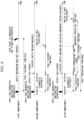
- FIG. 6 is a diagram showing examples of calculating a maximum time that can be driven in a fault state according to various embodiments.
- a fault that generates a malfunction of the vehicle 100 occurs (S610)
- a safety mechanism for handling the fault may not be operated or cannot be operated.
- a risk event due to the malfunction may occur (S613) after the fault tolerant time 615.
- the fault tolerant time 615 may be regarded as a time starting from the time point of occurring a fault that generates a malfunction (S610) until a risk event occurs due to the malfunction (S613).
- the vehicle 100 may execute a safety mechanism (S625).
- the vehicle 100 may perform a diagnostic test (S621) periodically, i.e., at regular time intervals.
- a diagnostic test S621
- a fault is detected (S623) after the fault detection time 622, and when a fault is detected, the vehicle 100 may respond to the fault by executing the safety mechanism (S625), and is switched to the safe state (S627) after a predetermined period of time.
- the fault tolerant time 624 may be regarded as a time starting from the time point of detecting a fault (S623) to the time point of switching to the safe state (S627).
- the vehicle 100 may execute a safety mechanism including an emergency operation (S635).
- the vehicle 100 may perform a diagnostic test (S631) periodically, i.e., at regular time intervals.
- the vehicle 100 may respond to the fault by executing the safety mechanism (S635), may perform an emergency operation during the emergency operation time 638 after the fault processing time 634, and may be switched to the safe state (S637) when the emergency operation is completed.
- the fault tolerant time 639 may be regarded as a time starting from the time point of detecting a fault (S638) to the time point of switching to the safe state (S637).
- the fault tolerant time may be the same as the emergency operation time 638 starting from the time point of completing the process of handling the fault to the time point of switching to the safe state (S637).
- the vehicle 100 may determine a fault tolerant distance based on expected speed information of the vehicle 100 using traffic flow information on the road where the vehicle is currently located.
- the vehicle 100 may search for full-shoulder stoppable areas that can be reached within the maximum distance or maximum time that can be driven, calculated at operation S510.
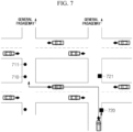
- FIG. 7 is a view showing an example for explaining the operation of FIG. 5 .
- the vehicle 100 may search for full-shoulder stoppable areas that can be reached within the maximum distance or maximum time that can be driven.
- the area where the full-shoulder stop is possible may be calculated considering the size of the vehicle 100, and the vehicle 100 may determine whether the full-shoulder stop is possible by grasping the size of an empty shoulder area and presence of obstacles.
- the full-shoulder stoppable areas may be indicated by black circles.
- the vehicle 100 may determine whether there is a stoppable area where route complexity is lower than or equal to a preset value, among a plurality of searched full-shoulder stoppable areas.
- the route complexity may be calculated considering factors such as the number of intersections to pass, the number of left turns, the number of right turns, the distance to the destination, and the like.
- the route complexity may be calculated by assigning a score of 3 points for one left turn, 2 points for one right turn, and 1 point for a distance of 1 Km. In the example of FIG.
- the route complexity of the stoppable area 710 may be calculated as a total of 6 points of one left turn (3 points) + one right turn (2 points) + a distance of 1Km (1 point), and the route complexity of the stoppable area 711 may have a value larger than that of the route complexity of the stoppable area 710 due to the distance.
- the route complexity may be calculated by assigning a different weight to each of the factors described above and determining contribution of each factor based on the weight.
- the vehicle 100 may proceed to operation S540, set a stoppable area where the route complexity is the lowest as the target point, and select the full-shoulder stop as the MRM type.
- the vehicle 100 may set the area where the route complexity is the lowest (e.g., 710) as the final target point among the two areas 710 and 711 with route complexity lower than or equal to a preset value.
- the vehicle 100 may proceed to operation S550, search for half-shoulder stoppable areas, and determine whether there is a half-shoulder stoppable area where the route complexity is lower than that of a full-shoulder stoppable area. According to another embodiment, at operation S550, the vehicle 100 may also determine whether there is a half-shoulder stoppable area where the route complexity is lower than a preset value.
- the vehicle 100 may proceed to operation S580, and select the in-lane stop or the straight stop as the MRM type.
- the vehicle 100 may proceed to operation S560, and determine whether the stopping risk at the half-shoulder stoppable area that satisfies a corresponding condition is lower than a preset risk.
- the stopping risk may be calculated based on the size of the stoppable area, whether it is a stopping prohibited area such as a crosswalk, firefighting facility, or the like, maximum speed information of the road, traffic flow information, and the like, and the stopping risk may be calculated by assigning a different weight to each factor.
- the half-shoulder stoppable area 720 of FIG. 7 when the half-shoulder stoppable area does not correspond to a designated stopping prohibited area, 0 points may be set, otherwise 3 points may be set, and when the maximum speed of the road is 40Km/h, 1 point may be set, when it is 50Km/h, 2 points may be set, and when it is 60Km/h, 3 points may be set.
- the stopping risk may be calculated as 2 points.
- the vehicle 100 may proceed to operation S580, and select the in-lane stop or the straight stop as the MRM type.
- the vehicle 100 may proceed to operation S570, and select a half-shoulder stop as the MRM type by setting a half-shoulder stoppable area where the stopping risk is the lowest as the target point.
- a preset risk e.g. 3 points
- half-shoulder stoppable areas 720 and 721 with route complexity lower than that of the full-shoulder stoppable areas, and among these, a half-shoulder stoppable area 720) with the lowest stopping risk is selected as the target point.
- FIG. 8 is a flowchart illustrating an operation of determining a target point and an MRM type in consideration of route complexity and stopping risk when performing a minimal risk maneuver of a vehicle according to other embodiments.
- the vehicle 100 or the MRM strategy determination unit 240 may calculate the maximum distance or maximum time that can be driven in an MRM state.
- the vehicle 100 may calculate the maximum distance or maximum time that can be driven in an MRM state based on the vehicle state information. The time until a serious risk event occurs may be calculated by calculating a fault tolerant time at the time point when the MRM is triggered. In addition, according to an embodiment, the vehicle 100 may detect a factor that generates a fault, and calculate a fault tolerance time including the time period of performing a safety mechanism. An example of calculating the fault tolerant time is shown in FIG. 6 , and since it has already been described, it is omitted here.
- the vehicle 100 may search for full-shoulder stoppable areas and half-shoulder stoppable areas that can be reached within the maximum distance or maximum time that can be driven, calculated at operation S810.
- the vehicle 100 may calculate route complexity and stopping risk at the searched full-shoulder stoppable areas and half-shoulder stoppable areas.
- the route complexity may be calculated equally for the full-shoulder stoppable areas and the half-shoulder stoppable areas.
- the route complexity may be calculated considering factors such as the number of intersections to pass, the number of left turns, the number of right turns, the distance to the destination, and the like.
- the route complexity may be calculated by assigning a score of 3 points for one left turn, 2 points for one right turn, and 1 point for a distance of 1 Km. In the example of FIG.
- the route complexity of the stoppable area 710 may be calculated as a total of 6 points of one left turn (3 points) + one right turn (2 points) + a distance of 1Km (1 point), and the route complexity of the stoppable area 711 may have a value larger than that of the route complexity of the stoppable area 710 due to the distance.
- the route complexity may be calculated by assigning a different weight to each of the factors described above and determining contribution of each factor based on the weight.
- the stopping risk may be calculated only for the half-shoulder stoppable areas. In the case of the full-shoulder stoppable area, as the entire vehicle may enter the shoulder stoppable area, the stopping risk may be regarded as 0.
- the stopping risk in the half-shoulder stoppable area may be calculated based on the size of the stoppable area, whether it is a stopping prohibited area such as a crosswalk, firefighting facility, or the like, maximum speed information of the road, traffic flow information, and the like, and the stopping risk may be calculated by assigning a different weight to each factor.
- the vehicle 100 may select a stoppable area where the route complexity is the lowest among the stoppable areas where the stopping risk is lower than a preset risk at operation S850. In the example of FIG. 7 , the vehicle 100 may select the half-shoulder stoppable area 720.
- the vehicle 100 may determine whether the stoppable area selected at operation S860 is a full-shoulder stoppable area, and when it is a full-shoulder stoppable area, the vehicle 100 may proceed to operation S880, select the full-shoulder stop as the MRM type, and set the stoppable area selected at operation S850 as the target point.
- various embodiments propose a method of improving safety while minimizing the risk of a vehicle, when a fault occurs during autonomous driving and the minimal risk maneuver (MRM) function is performed to reach the minimal risk condition, i.e., a stopped state,by selecting an MRM type and a target point based on route complexity and stopping risk at each stoppable area.
- MRM minimal risk maneuver
Landscapes
- Engineering & Computer Science (AREA)
- Transportation (AREA)
- Mechanical Engineering (AREA)
- Automation & Control Theory (AREA)
- Human Computer Interaction (AREA)
- Chemical & Material Sciences (AREA)
- Combustion & Propulsion (AREA)
- Traffic Control Systems (AREA)
Abstract
Description
- The present application claims priority to
Korean Patent Applications No. 10-2023-0112531, filed August 28, 2023 10-2024-0104458, filed August 06, 2024 - This document relates to a vehicle for performing a minimal risk maneuver and a method of operating the vehicle.
- Recently, advanced driver assistance systems (ADAS) are developed to help driving of drivers. The ADAS has a plurality of sub-technology categories and provides convenience to drivers. This ADAS is also called autonomous driving or Automated Driving System (ADS).
- Meanwhile, errors may occur in the autonomous driving system while a vehicle is performing autonomous driving. When an appropriate response is not taken to such abnormalities in the autonomous driving system, the vehicle may be placed in a dangerous state.
- Accordingly, various embodiments of this document disclose a vehicle that performs a minimal risk maneuver (MRM) to eliminate (or reduce) risk when a situation in which normal autonomous driving is not possible is detected during autonomous driving, and a method of operating the vehicle.
- Various embodiments of this document disclose a method and device for determining a minimal risk maneuver stopping type and a stopping location when a situation in which normal autonomous driving is not possible is detected in a vehicle during autonomous driving.
- Various embodiments of this document disclose a method and device for determining a minimal risk maneuver stopping type and a stopping location based on route complexity and stopping risk when a situation in which normal autonomous driving is not possible is detected in a vehicle during autonomous driving.
- Technical problems to be solved in this document are not limited to the technical problems mentioned above, and other unmentioned technical problems can be clearly understood by those skilled in the art from the description below.
- According to various embodiments of this document, an autonomous vehicle comprises at least one sensor for detecting a surrounding environment of the vehicle and generating surrounding environment information, a processor for generating vehicle state information by monitoring a state of the vehicle, and controlling autonomous driving of the vehicle and a controller for controlling an operation of the vehicle according to control of the processor.
- According to an embodiment, the processor may determine whether a minimal risk maneuver is needed based on at least one among the surrounding environment information and the vehicle state information during autonomous driving of the vehicle, determine a minimal risk maneuver type and a target point where the vehicle will stop when the minimal risk maneuver is needed, and control the vehicle to stop at the target point based on the determined minimal risk maneuver type and target point.
- According to an embodiment, the processor may calculate a maximum distance or a maximum time that can be driven in a minimum risk maneuver state, search for stoppable areas that can be reached within the maximum distance or the maximum time, classify the searched stoppable areas into full-shoulder stoppable areas and half-shoulder stoppable areas, calculate at least one among route complexity and stopping risk of each of the full-shoulder stoppable areas, determine whether or not stopping is possible at the full-shoulder stoppable areas based on at least one among the calculated route complexity and stopping risk, and calculate, when stopping is not possible in all of the full-shoulder stoppable areas, at least one among route complexity and stopping risk of each of the half-shoulder stoppable areas, and determine a minimal risk maneuver type and a target point where the vehicle will stop based on at least one among the route complexity and the stopping risk at the half-shoulder stoppable areas.
- According to an embodiment, the processor may calculate a maximum distance or a maximum time that can be driven in a minimum risk maneuver state, search for stoppable areas that can be reached within the maximum distance or the maximum time, calculate at least one among route complexity and stopping risk at the stoppable area, and determine a minimal risk maneuver type and a target point where the vehicle will stop based on the route complexity and the stopping risk of each of the stoppable areas.
- According to an embodiment, the processor may search for full-shoulder stoppable areas that can be reached within the maximum distance or the maximum time, calculate route complexity of each of the searched full-shoulder stoppable areas, determine a full-shoulder stoppable area where route complexity is lower than or equal to a preset value and having the lowest value as a target point where the vehicle will stop, and determine a full-shoulder stop as the minimal risk maneuver.
- According to an embodiment, the processor may search for half-shoulder stoppable areas, when there is no full-shoulder stoppable area where the route complexity is lower than or equal to a preset value, determine a half-shoulder stoppable area where the stopping risk is the lowest as a target point where the vehicle will stop and a half-shoulder stop as the minimal risk maneuver type, when there are half-shoulder stoppable areas where route complexity is lower than the route complexity of the full-shoulder stoppable areas and the stopping risk is lower than a preset risk, and determine an in-lane stop or a straight stop as the minimal risk maneuver type, when there is no half-shoulder stoppable area where the route complexity is lower than the route complexity of the full-shoulder stoppable areas.
- According to an embodiment, the processor may search for half-shoulder stoppable areas, when there is no full-shoulder stoppable area where the route complexity is lower than or equal to a preset value, determine a half-shoulder stoppable area where the stopping risk is the lowest as a target point where the vehicle will stop and a half-shoulder stop as the minimal risk maneuver type, when there are half-shoulder stoppable areas where route complexity is lower than or equal to the preset value and the stopping risk is lower than a preset risk, and determine an in-lane stop or a straight stop as the minimal risk maneuver type, when there is no half-shoulder stoppable area where the route complexity is lower than or equal to the preset value.
- According to an embodiment, the processor may search for full-shoulder stoppable areas and half-shoulder stoppable areas that can be reached within the maximum distance or the maximum time, calculate route complexity and stopping risk of each of the searched full-shoulder stoppable areas and half-shoulder stoppable areas, and select an in-lane stop or a straight stop as the minimal risk maneuver type when there is no stoppable area where the stopping risk is lower than a preset risk and the route complexity is lower than or equal to a preset value.
- According to an embodiment, the processor may select a stoppable area where the route complexity is the lowest among stoppable areas where the stopping risk is lower than a preset risk, when there are stoppable areas where the stopping risk is lower than a preset risk and the route complexity is lower than or equal to a preset value, determine a full-shoulder stop as the minimal risk maneuver type, and determine the selected stoppable area as a target point, when the selected stoppable area is a full-shoulder stoppable area, and determine a half-shoulder stop as the minimal risk maneuver type, and determine the selected stoppable area as a target point, when the selected stoppable area is not a full-shoulder stoppable area.
- According to an embodiment, the processor may calculate the route complexity based on the number of intersections to pass, the number of left turns, the number of right turns, and a distance to a destination.
- According to an embodiment, the processor may calculate the stopping risk based on a size of a stoppable area, whether an area is a stopping prohibited area, maximum speed information of a road, and traffic flow information.
- According to various embodiments of this document, an operation method of a vehicle may comprise: acquiring at least one among surrounding environment information and vehicle state information during autonomous driving of the vehicle; determining whether a minimal risk maneuver is needed based on at least one among the surrounding environment information and the vehicle statue information; determining a minimal risk maneuver type and a target point where the vehicle will stop, when it is determined that a minimal risk maneuver is needed; and controlling the vehicle to stop at the target point based on the determined minimal risk maneuver type and target point.
- According to an embodiment, the determining a minimal risk maneuver type and a target point may comprise calculating a maximum distance or a maximum time that can be driven in a minimum risk maneuver state; searching for stoppable areas that can be reached within the maximum distance or the maximum time; classifying the searched stoppable areas into full-shoulder stoppable areas and half-shoulder stoppable areas; calculating at least one among route complexity and stopping risk at the full-shoulder stoppable areas; determining whether or not stopping is possible at the full-shoulder stoppable areas based on at least one among the calculated route complexity and stopping risk; and calculating, when stopping is not possible in all of the full-shoulder stoppable areas, at least one among route complexity and stopping risk at the half-shoulder stoppable areas, and determining a minimal risk maneuver type and a target point where the vehicle will stop based on at least one among the route complexity and the stopping risk at the half-shoulder stoppable areas.
- According to an embodiment, the determining a minimal risk maneuver type and a target point may further comprise calculating a maximum distance or a maximum time that can be driven in a minimum risk maneuver state; searching for stoppable areas that can be reached within the maximum distance or the maximum time, calculating at least one among route complexity and stopping risk of each of the stoppable area; and determining a minimal risk maneuver type and a target point where the vehicle will stop based on the route complexity and the stopping risk of the stoppable areas.
- According to an embodiment, the determining a minimal risk maneuver type and a target point may further comprise searching for full-shoulder stoppable areas that can be reached within the maximum distance or the maximum time; calculating route complexity of the searched full-shoulder stoppable areas; determining a full-shoulder stoppable area where route complexity is lower than or equal to a preset value and having the lowest value as a target point where the vehicle will stop; and determining a full-shoulder stop as the minimal risk maneuver.
- According to an embodiment, the determining a minimal risk maneuver type and a target point may further comprise searching for half-shoulder stoppable areas, when there is no full-shoulder stoppable area where the route complexity is lower than or equal to a preset value; determining a half-shoulder stoppable area where the stopping risk is the lowest as a target point where the vehicle will stop and a half-shoulder stop as the minimal risk maneuver type, when there are half-shoulder stoppable areas where route complexity is lower than the route complexity of the full-shoulder stoppable areas and the stopping risk is lower than a preset risk; and determining an in-lane stop or a straight stop as the minimal risk maneuver type, when there is no half-shoulder stoppable area where the route complexity is lower than the route complexity of the full-shoulder stoppable areas.
- According to an embodiment, the determining a minimal risk maneuver type and a target point may further comprise searching for half-shoulder stoppable areas, when there is no full-shoulder stoppable area where the route complexity is lower than or equal to a preset value; determining a half-shoulder stoppable area where the stopping risk is the lowest as a target point where the vehicle will stop and a half-shoulder stop as the minimal risk maneuver type, when there are half-shoulder stoppable areas where route complexity is lower than or equal to the preset value and the stopping risk is lower than a preset risk; and determining an in-lane stop or a straight stop as the minimal risk maneuver type, when there is no half-shoulder stoppable area where the route complexity is lower than or equal to the preset value.
- According to an embodiment, the determining a minimal risk maneuver type and a target point may comprise searching for full-shoulder stoppable areas and half-shoulder stoppable areas that can be reached within the maximum distance or the maximum time; calculating route complexity and stopping risk at the searched full-shoulder stoppable areas and half-shoulder stoppable areas; and selecting an in-lane stop or a straight stop as the minimal risk maneuver type when there is no stoppable area where the stopping risk is lower than a preset risk and the route complexity is lower than or equal to a preset value.
- According to an embodiment, the determining a minimal risk maneuver type and a target point may further comprise selecting a stoppable area where the route complexity is the lowest among stoppable areas where the stopping risk is lower than a preset risk, when there are stoppable areas where the stopping risk is lower than a preset risk and the route complexity is lower than or equal to a preset value; determining a full-shoulder stop as the minimal risk maneuver type, and determines the selected stoppable area as a target point, when the selected stoppable area is a full-shoulder stoppable area; and determining a half-shoulder stop as the minimal risk maneuver type, and determines the selected stoppable area as a target point, when the selected stoppable area is not a full-shoulder stoppable area.
- According to an embodiment, the route complexity may be calculated based on the number of intersections to pass, the number of left turns, the number of right turns, and a distance to a destination.
- According to an embodiment, the stopping risk may be calculates based on a size of a stoppable area, whether an area is a stopping prohibited area, maximum speed information of a road, and traffic flow information.
-
-
FIG. 1 is a block diagram showing a vehicle according to various embodiments of this document. -
FIG. 2 is a functional block diagram showing a processor according to various embodiments of this document. -
FIG. 3 is a view showing minimal risk maneuver (MRM) strategies for each vehicle state according to various embodiments of this document. -
FIG. 4 is a flowchart illustrating an operation of performing a minimal risk maneuver of a vehicle according to various embodiments. -
FIG. 5 is a flowchart illustrating an operation of determining a target point and an MRM type in consideration of route complexity and stopping risk when performing a minimal risk maneuver of a vehicle according to various embodiments. -
FIG. 6 is a diagram showing examples of calculating a maximum time that can be driven in a fault state according to various embodiments. -
FIG. 7 is a view showing an example for explaining the operation ofFIG. 5 . -
FIG. 8 is a flowchart illustrating an operation of determining a target point and an MRM type in consideration of route complexity and stopping risk when performing a minimal risk maneuver of a vehicle according to other embodiments. - Hereinafter, embodiments of this document will be described in detail with reference to the accompanying drawings.
- The configuration of this document and operation effects according thereto will be clearly understood through the detailed description below. Prior to detailed description of this document, like components are indicated by like symbols as much as possible although the components are shown in different drawings, and it should be noted that when it is determined that known configurations may obscure the gist of the present disclosure, detailed description thereof will be omitted.
- Prior to detailed description of this document, terms used in this document may be defined as follows.
- A vehicle is provided with an Automated Driving System (ADS) and is capable of autonomous driving. For example, the vehicle may perform at least one among steering, acceleration, deceleration, lane change, and stopping (or halt) by the ADS without handling of the driver. The ADS may include, for example, at least one among Pedestrian Detection and Collision Mitigation System (PDCMS), Lane Change Decision Aid System (LCDAS), Lane Departure Warning System (LDWS), Adaptive Cruise Control (ACC), Lane Keeping Assistance System (LKAS), Road Boundary Departure Prevention System (RBDPS), Curve Speed Warning System (CSWS), Forward Vehicle Collision Warning System (FVCWS), and Low Speed Following (LSF).
- A driver is a human who uses the vehicle and is provided with services of the autonomous driving system.
- Vehicle control authority is the authority of controlling at least one component of the vehicle and/or at least one function of the vehicle. At least one function of the vehicle may include, for example, at least one among a steering function, an acceleration function, a deceleration function (or braking function), a lane change function, a lane detection function, a lateral control function, an obstacle recognition and distance detection function, a powertrain control function, a safe area detection function, an engine on/off function, power on/off, and vehicle locking/unlocking. The listed vehicle functions are only examples for helping understanding, and the embodiments of this document are not limited thereto.
- A shoulder may mean a space between the outermost road boundary (or outermost lane boundary) and the road edge (e.g., curb, guardrail) in the direction in which the vehicle is driving.
-
FIG. 1 is a block diagram showing a vehicle according to various embodiments of this document. - The configuration of the vehicle shown in
FIG. 1 is an example, and each component may be configured of one chip, one part, or one electronic circuit, or may be configured of a combination of chips, parts, and/or electronic circuits. According to an embodiment, some of the components shown inFIG. 1 may be separated into a plurality of components and configured as different chips, different parts, or different electronic circuits, and some components may be combined to be configured as one chip, one part, or one electronic circuit. According to an embodiment, some of the components shown inFIG. 1 may be omitted, or other components not shown may be added. -
FIG. 2 is a functional block diagram showing a processor according to various embodiments of this document, andFIG. 3 is a view showing minimal risk maneuver (MRM) strategies for each vehicle state according to various embodiments of this document. - Referring to
FIG. 1 , avehicle 100 may include asensor unit 110, acontroller 120, aprocessor 130, adisplay 140, acommunication device 150, and amemory 160. - According to various embodiments, the
sensor unit 110 may sense the environment around thevehicle 100 using at least one sensor, and generate data related to the surrounding environment based on the sensing result. According to an embodiment, thesensor unit 110 may acquire road information, information on the objects around the vehicle (e.g., other vehicles, people, objects, curbs, guardrails, lanes, obstacles), and/or location information of the vehicle based on the sensing data acquired from at least one sensor. The road information may include, for example, at least one among the locations of lanes, shapes of lanes, colors of lanes, types of lanes, number of lanes, presence of a shoulder, and the size of the shoulder. Objects around the vehicle may include, for example, at least one among the locations of the objects, sizes of the objects, shapes of the objects, distances to the objects, and relative speed with respect to the objects. - According to an embodiment, the
sensor unit 110 may include at least one among a camera, light detection and ranging (LIDAR), radio detection and ranging (RADAR), an ultrasonic sensor, an infrared sensor, and a position measurement sensor. The listed sensors are only examples for helping understanding, and the sensors included in thesensor unit 110 of this document are not limited thereto. The camera may capture images around the vehicle and generate image data including lanes and/or surrounding objects on the front, rear, and/or lateral sides of thevehicle 100. The LiDAR may generate information on the objects located in the front, rear, and/or lateral sides of thevehicle 100 using light (or laser). The radar may generate information on the objects located in the front, rear, and/or lateral sides of thevehicle 100 using electromagnetic waves (or radio waves). The ultrasonic sensor may generate information on the objects located in the front, rear, and/or lateral sides of thevehicle 100 using ultrasonic waves. The infrared sensor may generate information on the objects located in the front, rear, and/or lateral sides of thevehicle 100 using infrared rays. The position measurement sensor may measure the current position of thevehicle 100. The position measurement sensor may include at least one among a Global Positioning System (GPS) sensor, a Differential Global Positioning System (DGPS) sensor, and a Global Navigation Satellite System (GNSS) sensor. The position measurement sensor may generate position data of the vehicle based on the signal generated by at least one among a GPS sensor, a DGPS sensor, and a GNSS sensor. - According to various embodiments, the
controller 120 may control the operation of at least one component of thevehicle 100 and/or at least one function of the vehicle under the control of theprocessor 130. At least one function may include, for example, a steering function, an acceleration function (or a longitudinal acceleration function), a deceleration function (or a longitudinal deceleration function, a braking function), a lane change function, a lane detection function, an obstacle recognition and distance detection function, a lateral control function, a powertrain control function, a safe area detection function, engine on/off, power on/off, and vehicle locking/unlocking. - According to an embodiment, the
controller 120 may control the operation of at least one component of the vehicle and/or at least one function of the vehicle for autonomous driving and/or minimal risk maneuver (MRM) of thevehicle 100 under the control of theprocessor 130. For example, thecontroller 120 may control at least one operation among a steering function, an acceleration function, a deceleration function, a lane change function, a lane detection function, a lateral control function, an obstacle recognition and distance detection function, a powertrain control function, and a safe area detection function for the minimal risk maneuver. - According to various embodiments, the
processor 130 may control the overall operation of thevehicle 100. According to an embodiment, theprocessor 130 may include an electrical control unit (ECU) that can control the components inside thevehicle 100 in an integrated manner. For example, theprocessor 130 may include a central processing unit (CPU) or a micro controller unit (MCU) capable of performing operation processing. - According to various embodiments, when a designated event occurs, the
processor 130 may activate the Automated Driving System (ADS) to control the components inside thevehicle 100 so that the vehicle may perform autonomous driving. The designated event may occur when autonomous driving of the vehicle is requested, when the vehicle control authority is delegated from the driver, or when conditions designated by the driver and/or designer are satisfied. - According to various embodiments, the
processor 130 may determine whether normal autonomous driving is possible based on at least one among the vehicle state information and the surrounding environment information during the autonomous driving. When normal autonomous driving is not possible, theprocessor 130 may determine an MRM strategy and control the vehicle to stop according to the determined MRM strategy. Here, the MRM strategy may be a strategy of stopping the vehicle at a stopping location determined according to the determined MRM type. - According to an embodiment, the
processor 130 may include a vehicle stateinformation acquisition unit 210, a surrounding environmentinformation acquisition unit 220, and an MRMstrategy determination unit 240, as shown inFIG. 2 . - The vehicle state
information acquisition unit 210 may acquire vehicle state information indicating whether a mechanical and/or electrical defect occurs in the components inside the vehicle by monitoring the mechanical and/or electrical states of the components (e.g., sensors, actuators, etc.) inside the vehicle from the time point when the ADS is activated. The vehicle state information may include information on the mechanical and/or electrical states of the components inside the vehicle. For example, the vehicle state information may include information indicating whether the functions required for autonomous driving may operate normally according to the mechanical and/or electrical states of the components inside the vehicle. - The surrounding environment
information acquisition unit 220 may acquire environment information around the vehicle using thesensor unit 110 and/or thecommunication device 150 from the time point when the ADS is activated. The surrounding environmentinformation acquisition unit 220 may include a roadinformation acquisition unit 221 for acquiring information on the road on which the vehicle is driving and surrounding roads, and a surrounding objectinformation acquisition unit 223 for detecting objects around the vehicle from thesensor unit 110. - According to an embodiment, the road
information acquisition unit 221 may acquire road information around the location where the vehicle is driving through thesensor unit 110. According to an embodiment, the roadinformation acquisition unit 221 may acquire road information around the location where the vehicle is driving based on map information acquired from an external device (e.g., another vehicle, or a server) through thecommunication device 150 or built-in map information and the location information of the vehicle. - According to an embodiment, the surrounding object
information acquisition unit 223 may acquire information on the objects around the vehicle (e.g., other vehicles, people, objects, curbs, guardrails, lanes, obstacles) through thesensor unit 110. For example, the surrounding objectinformation acquisition unit 223 may acquire the distance and relative speed of at least one vehicle located in the front, lateral, and/or rear side of the vehicle. - According to an embodiment, the
processor 130 may determine whether the functions required for autonomous driving may operate normally based on the vehicle state information. The functions required for autonomous driving may include at least one among, for example, a lane detection function, a lane change function, a lateral control function, a deceleration (or brake control) function, an acceleration control function, a powertrain control function, a safe area detection function, and an obstacle recognition and distance detection function. When at least one function required for autonomous driving is unable to operate normally, theprocessor 130 may determine that normal autonomous driving is not possible. - According to an embodiment, the
processor 130 may determine whether the vehicle state is suitable for general driving conditions based on the vehicle state information. For example, theprocessor 130 may determine whether the mechanical state information (e.g., tire pressure information, or engine overheating information) of the vehicle is suitable for general driving conditions. When the vehicle state is unsuitable for general driving conditions, theprocessor 130 may determine that normal autonomous driving is not possible. For example, when driving of the vehicle is not possible due to tire pressure or engine overheating, theprocessor 130 may determine that normal autonomous driving is not possible. - According to an embodiment, the
processor 130 may determine whether the environment around the vehicle is suitable for the operation design domain (ODD) of autonomous driving based on at least one piece of surrounding environment information. The operation design domain may represent conditions for the surrounding environment in which autonomous driving operates normally. When the surrounding environment information of the vehicle does not match the operation design domain, theprocessor 130 may determine that normal autonomous driving is not possible. - According to various embodiments, when normal autonomous driving is not possible, the
processor 130 may determine that this is a situation in which a minimal risk maneuver for minimizing the risk of accident needs to be performed. When this is a situation in which a minimal risk maneuver needs to be performed, theprocessor 130 may select a minimal risk maneuver strategy among a plurality of minimal risk maneuver strategies using the MRMstrategy determination unit 240. The minimal risk maneuver strategies may include four types as shown inFIG. 3 . For example, the minimal risk maneuver strategies include aTraffic Lane Stop 301strategy including type 1 andtype 2, and aRoad Shoulders Stop 303strategy including type 3 andtype 4. - The
traffic lane stop 301 strategy may include astraight stop 311 oftype 1 and an in-lane stop 312 oftype 2. The road shoulders stop 303 strategy may include a half-shoulder stop 313 oftype 3 and a full-shoulder stop 314 oftype 4. - The
straight stop 311 oftype 1 is a type of stopping usingonly deceleration control 323, which is a longitudinal deceleration function, and does not involve lateral control. For example, thestraight stop 311 may be performed in a situation where lane detection is not possible or lateral control is not possible due to the defect of the actuator. In the case of thestraight stop 311 oftype 1,acceleration control 322 andlane change 324 are prohibited or not possible, and a function of detecting a potential stopping location out oftraffic lane 325 may not be needed. Here, detecting a potential stopping location out of traffic lane may mean a function of detecting locations of safe areas located outside the traffic lanes, such as a shoulder or drowsy rest area. - The in-
lane stop 312 oftype 2 is a type of stopping within the boundary of a lane in which the vehicle is driving. For example, the in-lane stop 312 may refer to a type in which a vehicle stops within the boundary of a lane in which the vehicle is driving throughlateral control 321 and/ordeceleration control 323. The driving lane may mean a lane in which the vehicle is driving at the time point when it is determined that the minimal risk maneuver needs to be performed. In the case of the in-lane stop 312,acceleration control 322 andlane change 324 are prohibited, and the function of detecting a potential stopping location out oftraffic lane 325 may not be needed. - The half-
shoulder stop 313 oftype 3 is a type of stopping while a part of the vehicle is located on the shoulder of the road, and the full-shoulder stop 314 oftype 4 is a type of stopping while the entire vehicle is stopped on the shoulder of the road. The functions oflateral control 321,deceleration control 323,lane change 324, and detecting a potential stopping location out oftraffic lane 325 may be used in the half-shoulder stop 313 and the full-shoulder stop 314, and theacceleration control 322 may only be used to maintain the current speed. - According to an embodiment, priorities of the MRM types described above may be determined based on the roads, surrounding environments, and vehicle's fail-operational capability. For example, in order to minimize the risk at the time of stopping, priorities of MRM types corresponding to the road shoulders stop 303 strategy may be set higher than those of MRM types corresponding to the
traffic lane stop 301 strategy. In addition, the priority of the full-shoulder stop 314 may be set higher than that of the half-shoulder stop 313, and the priority of the in-lane stop 312 may be set higher than that of thestraight stop 311. That is, the priorities of MRM types may be set to decrease in order of the full-shoulder stop 314, half-shoulder stop 313, in-lane stop 312, andstraight stop 311. - According to various embodiments, the MRM
strategy determination unit 240 of theprocessor 130 may select an MRM strategy based on at least one among vehicle state information and surrounding environment information. - According to an embodiment, the MRM
strategy determination unit 240 may confirm an MRM type that can be performed among the MRM types mentioned above based on the functions that operate normally and/or functions that cannot operate normally among the functions required for autonomous driving based on the vehicle state information. For example, when thelateral control 321 function operates normally, it can be determined that all of thestraight stop 311, in-lane stop 312, half-shoulder stop 313, and full-shoulder stop 314 may be performed. As another example, when thelateral control 321 function does not operate normally, the MRM type that can be performed may be determined to include only thestraight stop 311. - When there is only one MRM type that can be performed, which is confirmed based on the vehicle state information, the MRM
strategy determination unit 240 may determine the MRM type as the MRM strategy. For example, the MRMstrategy determination unit 240 may determine thestraight stop 311 as the MRM strategy since only thestraight stop 311 can be performed in a situation where thelateral control 321 function does not operate normally. As another example, the MRMstrategy determination unit 240 may determine thestraight stop 311 as the MRM strategy since only thestraight stop 311 can be performed when driving lanes are not detected due to a sensor defect and/or external environment. - When there is a plurality of MRM types that can be performed, which is confirmed based on the vehicle state information, the MRM
strategy determination unit 240 may determine an MRM type that can be performed within a designated minimal risk condition (MRC) range. According to an embodiment, the designated MRC range may be set and/or changed by an operator and/or a designer. According to an embodiment, the designated MRC range may be set differently according to the vehicle performance, vehicle type, and/or external environmental factors (e.g., weather, time, etc.). - According to an embodiment, the MRM
strategy determination unit 240 may determine an MRM type that can be performed within the MRC range based on whether there is a shoulder within the designated MRC range. When there is no shoulder within the designated MRC range, the MRMstrategy determination unit 240 may determine the in-lane stop 312 or thestraight stop 311 as the MRM type that can be performed within the MRC range. - When there is a shoulder within the designated MRC range, the MRM
strategy determination unit 240 may determine an MRM type that can be performed within the MRC range based on the size of the shoulder. When the size of the shoulder within the designated MRC range is greater than or equal to a designated size, the MRMstrategy determination unit 240 may determine the full-shoulder stop 314, the half-shoulder stop 313, the in-lane stop 312, or thestraight stop 311 as the MRM type that can be performed within the MRC range. The designated size may be determined based on the size of the vehicle. When the size of the shoulder is smaller than the designated size, the MRMstrategy determination unit 240 may determine the half-shoulder stop 313, the in-lane stop 312, or thestraight stop 311 as the MRM type that can be performed within the MRC range. - According to various embodiments, when there is a plurality of MRM types that can be performed within the designated MRC range, the MRM
strategy determination unit 240 may select a final MRM strategy considering the priorities and/or surrounding object information. - According to an embodiment, when there is a plurality of MRM types that can be performed within the designated MRC range, the MRM
strategy determination unit 240 may selects an MRM type of the highest priority among the MRM types that can be performed within the designated MRC range as the final MRM strategy. -
FIG. 4 is a flowchart illustrating an operation of performing a minimal risk maneuver of a vehicle according to various embodiments. - Referring to
FIG. 4 , at operation S10, thevehicle 100 may acquire a request for starting a minimal risk maneuver (MRM). According to embodiments, theprocessor 130 may generate a request for starting a minimal risk maneuver function when the engine of thevehicle 100 is turned on and thevehicle 100 begins to move at a predetermined speed or higher. Alternatively, theprocessor 130 may acquire state information of thevehicle 100 and surroundings of thevehicle 100, and generate a minimal risk maneuver request based on the acquired state information. Alternatively, theprocessor 130 may acquire a minimal risk maneuver request from the outside received through thecommunication device 150 or thesensor 110. The minimal risk maneuver request may mean a command that directs thevehicle 100 to perform a minimal risk maneuver. - At operation S20, the
vehicle 100 may execute a minimal risk maneuver function when there is a minimal risk maneuver request. - The minimal risk maneuver function may include an operation of monitoring the state of a vehicle (S21), an operation of determining an MRM type (S23), and an operation of executing the determined MRM type (S25).
- When a minimal risk maneuver request is acquired (S10), the
vehicle 100 may monitor the state of thevehicle 100 at operation S21. At operation S21, thevehicle 100 may check the state of the autonomous driving system and/or the vehicle, analyze severity when there is a fault, and recognize the effect on the autonomous driving system and/or the vehicle. In addition, thevehicle 100 may check the states of related system components to determine the performance and capability of the current dynamic driving task (DDT) of the autonomous driving system. - According to embodiments, the
vehicle 100 may monitor the states of components of thevehicle 100 and the environment information around thevehicle 100 using the vehicle stateinformation acquisition unit 210 and the surrounding environmentinformation acquisition unit 220. Thevehicle 100 may monitor the state of each component of thevehicle 100 and the environment information around thevehicle 100, for example, lanes, surrounding vehicle information, and the like, in real time. Thevehicle 100 may determine which sensors or components are currently available (or operable) among thesensors 110. - At operation S23, the
vehicle 100 may determine an MRM type for emergency stopping based on the acquired vehicle state information and surrounding environment information. According to various embodiments, the MRM type of a vehicle may include a straight stop, an in-lane stop, a half-shoulder stop, and a full-shoulder stop as shown inFIG. 3 . However, it is not limited thereto, and additional MRM types may be included in other embodiments. - The
vehicle 100 may determine an MRM type suitable for the current fault state based on the determination result of the fault state. According to an embodiment, when only deceleration control of the vehicle is possible, only the straight stop may be selected as a type that can be realized. According to another embodiment, when steering control and deceleration control of the vehicle are possible, the type of in-lane stop may be selected in addition to the straight stop. According to another embodiment, when a lane change function and a shoulder detection function among the autonomous driving functions are possible, as well as the steering control and the deceleration control of the vehicle, the types of half-shoulder stop and full-shoulder stop may also be selected. - When the
vehicle 100 executes the MRM type determined at operation S25 according to the determination at operation S23 and finally reaches aminimal risk state 30, e.g., a stopped state, the minimal risk maneuver function may be terminated. - According to an embodiment, it is general that the
vehicle 100 maintains the initial MRM type determined at operation S23 and executes the MRM at operation S25 according thereto. When a serious change occurs in internal or external factors or it is determined that the selected MRM type cannot be performed due to a change in the traffic situation, thevehicle 100 may change the MRM type. At this point, when the MRM type needs to be changed while performing an MRM already determined at operation S25, thevehicle 100 may change the MRM type in a reasonable and safe manner without delaying reaching the minimal risk condition. - According to an embodiment, when a person, including the driver, intervenes 40 to take over the DDT at any time point while the
vehicle 100 is performing the minimal risk maneuver function, all the autonomous driving functions, including the minimal risk maneuver function, can be terminated, and the person may acquire the right to control the vehicle. - As described above, the operation of determining an MRM type at operation S23 of
FIG. 4 may be performed by the MRMstrategy determination unit 240 of thevehicle 100. - According to an embodiment, the MRM
strategy determination unit 240 may generate a vehicle control command based on the determined MRM type and/or target point and transmits the vehicle control command to thecontroller 120, and thecontroller 120 may control thevehicle 100 based on the command to execute the determined MRM type and make thevehicle 100 satisfy the minimal risk condition at the target point. According to another embodiment, thecontroller 120 may acquire the MRM type and the target point from the MRMstrategy determination unit 240, and perform vehicle control by itself so that the MRM type is executed and thevehicle 100 satisfies the minimal risk condition at the target point. - The MRM
strategy determination unit 240 may determine the MRM type based on the vehicle state information and the surrounding environment information and determine, at the same time, a point that satisfies the minimal risk condition, i.e., a target point where thevehicle 100 will stop. - As described above, the MRM types may have priorities set to decrease in order of the full-
shoulder stop 314, half-shoulder stop 313, in-lane stop 312, andstraight stop 311. Therefore, in the cases other than special situations, such as when thelateral control 321 function does not operate normally, the MRMstrategy determination unit 240 may determine the MRM type according to the priorities described above. - However, when the stopping target point for the half-shoulder stop corresponds to a safe place close to the current location of the vehicle, selecting the half-shoulder stop, rather than the full-shoulder stop where the stopping target point is far away, may be a more reasonable minimal risk maneuver. That is, determining an MRM type by the MRM
strategy determination unit 240 based on the complexity of the route to the stopping point and the stopping risk at the stopping point, rather than simply determining the MRM type based on the set priorities, may further contribute to safety of the vehicle. -
FIG. 5 is a flowchart illustrating an operation of determining a target point and an MRM type in consideration of route complexity and stopping risk when performing a minimal risk maneuver of a vehicle according to various embodiments. - When there is an MRM request as shown in
FIG. 4 , at operation S510, thevehicle 100 or the MRMstrategy determination unit 240 may calculate the maximum distance or maximum time that can be driven in an MRM state. - According to an embodiment, the
vehicle 100 may calculate the maximum distance or maximum time that can be driven in an MRM state based on the vehicle state information. The time until a serious risk event occurs may be calculated by calculating a fault tolerant time at the time point when the MRM is triggered. In addition, according to an embodiment, thevehicle 100 may detect a factor that generates a fault, and calculate a fault tolerance time including the time period of performing a safety mechanism. -
FIG. 6 is a diagram showing examples of calculating a maximum time that can be driven in a fault state according to various embodiments. - Referring to
FIG. 6 , in a first embodiment, although a fault that generates a malfunction of thevehicle 100 occurs (S610), a safety mechanism for handling the fault may not be operated or cannot be operated. Then, a risk event due to the malfunction may occur (S613) after the faulttolerant time 615. In the first embodiment, the faulttolerant time 615 may be regarded as a time starting from the time point of occurring a fault that generates a malfunction (S610) until a risk event occurs due to the malfunction (S613). - Referring to
FIG. 6 , in a second embodiment, when a fault that generates a malfunction (S620) is detected (S623), thevehicle 100 may execute a safety mechanism (S625). According to an embodiment, thevehicle 100 may perform a diagnostic test (S621) periodically, i.e., at regular time intervals. When the diagnostic test (S621) is performed after a fault that generates a malfunction (S620) is detected, a fault is detected (S623) after thefault detection time 622, and when a fault is detected, thevehicle 100 may respond to the fault by executing the safety mechanism (S625), and is switched to the safe state (S627) after a predetermined period of time. In the second embodiment, the faulttolerant time 624 may be regarded as a time starting from the time point of detecting a fault (S623) to the time point of switching to the safe state (S627). - Referring to
FIG. 6 , in a third embodiment, when a fault that generates a malfunction (S630) is detected (S632), thevehicle 100 may execute a safety mechanism including an emergency operation (S635). According to an embodiment, thevehicle 100 may perform a diagnostic test (S631) periodically, i.e., at regular time intervals. When the diagnostic test (S631) is performed after a fault that generates a malfunction (S630) is detected, a fault is detected (S633) after thefault detection time 632, and when a fault is detected, thevehicle 100 may respond to the fault by executing the safety mechanism (S635), may perform an emergency operation during theemergency operation time 638 after thefault processing time 634, and may be switched to the safe state (S637) when the emergency operation is completed. In the third embodiment, the faulttolerant time 639 may be regarded as a time starting from the time point of detecting a fault (S638) to the time point of switching to the safe state (S637). Alternatively, according to another embodiment, the fault tolerant time may be the same as theemergency operation time 638 starting from the time point of completing the process of handling the fault to the time point of switching to the safe state (S637). - When the fault tolerant time is determined, the
vehicle 100 may determine a fault tolerant distance based on expected speed information of thevehicle 100 using traffic flow information on the road where the vehicle is currently located. - Referring to
FIG. 5 again, at operation S520, thevehicle 100 may search for full-shoulder stoppable areas that can be reached within the maximum distance or maximum time that can be driven, calculated at operation S510. -
FIG. 7 is a view showing an example for explaining the operation ofFIG. 5 . - Referring to the embodiment of
FIG. 7 , thevehicle 100 may search for full-shoulder stoppable areas that can be reached within the maximum distance or maximum time that can be driven. According to an embodiment, the area where the full-shoulder stop is possible may be calculated considering the size of thevehicle 100, and thevehicle 100 may determine whether the full-shoulder stop is possible by grasping the size of an empty shoulder area and presence of obstacles. In the example ofFIG. 7 , the full-shoulder stoppable areas may be indicated by black circles. - At operation S530, the
vehicle 100 may determine whether there is a stoppable area where route complexity is lower than or equal to a preset value, among a plurality of searched full-shoulder stoppable areas. Here, the route complexity may be calculated considering factors such as the number of intersections to pass, the number of left turns, the number of right turns, the distance to the destination, and the like. For example, the route complexity may be calculated by assigning a score of 3 points for one left turn, 2 points for one right turn, and 1 point for a distance of 1 Km. In the example ofFIG. 7 , the route complexity of thestoppable area 710 may be calculated as a total of 6 points of one left turn (3 points) + one right turn (2 points) + a distance of 1Km (1 point), and the route complexity of thestoppable area 711 may have a value larger than that of the route complexity of thestoppable area 710 due to the distance. - According to an embodiment, the route complexity may be calculated by assigning a different weight to each of the factors described above and determining contribution of each factor based on the weight. In the example of
FIG. 7 , there are three full-shoulder stoppable areas, and route complexity of two of the full-shoulderstoppable areas - When the
vehicle 100 determines that there is a stoppable area where route complexity is lower than or equal to a preset value as a result of the determination at operation S530, thevehicle 100 may proceed to operation S540, set a stoppable area where the route complexity is the lowest as the target point, and select the full-shoulder stop as the MRM type. In the example ofFIG. 7 , thevehicle 100 may set the area where the route complexity is the lowest (e.g., 710) as the final target point among the twoareas - When the
vehicle 100 determines that there is no stoppable area where route complexity is lower than or equal to a preset value as a result of the determination at operation S530, thevehicle 100 may proceed to operation S550, search for half-shoulder stoppable areas, and determine whether there is a half-shoulder stoppable area where the route complexity is lower than that of a full-shoulder stoppable area. According to another embodiment, at operation S550, thevehicle 100 may also determine whether there is a half-shoulder stoppable area where the route complexity is lower than a preset value. - When the
vehicle 100 determines that there is no half-shoulder stoppable area that satisfies a corresponding condition as a result of the determination at operation S550, thevehicle 100 may proceed to operation S580, and select the in-lane stop or the straight stop as the MRM type. - When the
vehicle 100 may determine that there is a half-shoulder stoppable area that satisfies a corresponding condition as a result of the determination at operation S550, thevehicle 100 may proceed to operation S560, and determine whether the stopping risk at the half-shoulder stoppable area that satisfies a corresponding condition is lower than a preset risk. Here, the stopping risk may be calculated based on the size of the stoppable area, whether it is a stopping prohibited area such as a crosswalk, firefighting facility, or the like, maximum speed information of the road, traffic flow information, and the like, and the stopping risk may be calculated by assigning a different weight to each factor. For example, when the half-shoulder stoppable area does not correspond to a designated stopping prohibited area, 0 points may be set, otherwise 3 points may be set, and when the maximum speed of the road is 40Km/h, 1 point may be set, when it is 50Km/h, 2 points may be set, and when it is 60Km/h, 3 points may be set. In addition, taking the half-shoulderstoppable area 720 ofFIG. 7 as an example, when the half-shoulder stoppable area does not correspond to the designated stopping prohibited area (0 points), and the maximum speed on the road is 40 km/h (1 point), and the degree of occupying the road is 1/4 (1 point), the stopping risk may be calculated as 2 points. - When there is no half-shoulder stoppable area having a stopping risk lower than a preset risk as a result of the determination at operation S560, the
vehicle 100 may proceed to operation S580, and select the in-lane stop or the straight stop as the MRM type. - When there is a half-shoulder stoppable area having a stopping risk lower than a preset risk (e.g., 3 points) as a result of the determination at operation S560, the
vehicle 100 may proceed to operation S570, and select a half-shoulder stop as the MRM type by setting a half-shoulder stoppable area where the stopping risk is the lowest as the target point. - Referring to the example of
FIG. 7 , there are half-shoulderstoppable areas -
FIG. 8 is a flowchart illustrating an operation of determining a target point and an MRM type in consideration of route complexity and stopping risk when performing a minimal risk maneuver of a vehicle according to other embodiments. - When there is an MRM request as shown in
FIG. 4 , at operation S810, thevehicle 100 or the MRMstrategy determination unit 240 may calculate the maximum distance or maximum time that can be driven in an MRM state. - According to an embodiment, the
vehicle 100 may calculate the maximum distance or maximum time that can be driven in an MRM state based on the vehicle state information. The time until a serious risk event occurs may be calculated by calculating a fault tolerant time at the time point when the MRM is triggered. In addition, according to an embodiment, thevehicle 100 may detect a factor that generates a fault, and calculate a fault tolerance time including the time period of performing a safety mechanism. An example of calculating the fault tolerant time is shown inFIG. 6 , and since it has already been described, it is omitted here. - At operation S820, the
vehicle 100 may search for full-shoulder stoppable areas and half-shoulder stoppable areas that can be reached within the maximum distance or maximum time that can be driven, calculated at operation S810. - At operation S830, the
vehicle 100 may calculate route complexity and stopping risk at the searched full-shoulder stoppable areas and half-shoulder stoppable areas. Here, the route complexity may be calculated equally for the full-shoulder stoppable areas and the half-shoulder stoppable areas. As described above, the route complexity may be calculated considering factors such as the number of intersections to pass, the number of left turns, the number of right turns, the distance to the destination, and the like. For example, the route complexity may be calculated by assigning a score of 3 points for one left turn, 2 points for one right turn, and 1 point for a distance of 1 Km. In the example ofFIG. 7 , the route complexity of thestoppable area 710 may be calculated as a total of 6 points of one left turn (3 points) + one right turn (2 points) + a distance of 1Km (1 point), and the route complexity of thestoppable area 711 may have a value larger than that of the route complexity of thestoppable area 710 due to the distance. - According to an embodiment, the route complexity may be calculated by assigning a different weight to each of the factors described above and determining contribution of each factor based on the weight.
- The stopping risk may be calculated only for the half-shoulder stoppable areas. In the case of the full-shoulder stoppable area, as the entire vehicle may enter the shoulder stoppable area, the stopping risk may be regarded as 0. The stopping risk in the half-shoulder stoppable area may be calculated based on the size of the stoppable area, whether it is a stopping prohibited area such as a crosswalk, firefighting facility, or the like, maximum speed information of the road, traffic flow information, and the like, and the stopping risk may be calculated by assigning a different weight to each factor.
- At operation S840, the
vehicle 100 may determine whether there is a stoppable area where the stopping risk is lower than a preset risk and the route complexity is lower than or equal to a preset value. In the case of the full-shoulder stoppable area, as the stopping risk of thevehicle 100 may be regarded as 0, only whether the route complexity is lower than or equal to a preset value can be determined. For example, thevehicle 100 may determine that the full-shoulderstoppable areas stoppable area 720 satisfy the conditions of operation S840 by calculating the route complexity and the stopping risk for the full-shoulder stoppable areas (black circles) and the half-shoulder stoppable areas (black squares) inFIG. 7 . - When the
vehicle 100 determines that there is no stoppable area that satisfies the conditions of operation S840 as a result of the determination at operation S840, thevehicle 100 may proceed to operation S870 and select the in-lane stop or the straight stop as the MRM type. - When the
vehicle 100 determines that there is a stoppable area that satisfies the conditions of operation S840 as a result of the determination at operation S840, thevehicle 100 may select a stoppable area where the route complexity is the lowest among the stoppable areas where the stopping risk is lower than a preset risk at operation S850. In the example ofFIG. 7 , thevehicle 100 may select the half-shoulderstoppable area 720. - The
vehicle 100 may determine whether the stoppable area selected at operation S860 is a full-shoulder stoppable area, and when it is a full-shoulder stoppable area, thevehicle 100 may proceed to operation S880, select the full-shoulder stop as the MRM type, and set the stoppable area selected at operation S850 as the target point. - When the
vehicle 100 determines that the stoppable area selected at operation S860 is not a full-shoulder stoppable area, thevehicle 100 may proceed to operation S890, select the half-shoulder stop as the MRM type, and set the stoppable area selected at operation S850 as the target point. - As described above, various embodiments propose a method of improving safety while minimizing the risk of a vehicle, when a fault occurs during autonomous driving and the minimal risk maneuver (MRM) function is performed to reach the minimal risk condition, i.e., a stopped state,by selecting an MRM type and a target point based on route complexity and stopping risk at each stoppable area.
- According to various embodiments of this document, when a vehicle detects a situation in which normal autonomous driving is not possible during autonomous driving and determines to stop on the shoulder using a minimal risk maneuver strategy, as an optimal stopping type and stopping location are determined by determining route complexity and stopping risk, vehicle risk is minimized, and safety can be improved.
Claims (16)
- An autonomous vehicle comprising:at least one sensor for detecting a surrounding environment of the vehicle and generating surrounding environment information;a processor for generating vehicle state information by monitoring a state of the vehicle, and controlling autonomous driving of the vehicle; anda controller for controlling an operation of the vehicle according to control of the processor,wherein the processor is configured to:determine whether a minimal risk maneuver is needed based on at least one among the surrounding environment information and the vehicle state information during autonomous driving of the vehicle,determine a minimal risk maneuver type and a target point where the vehicle will stop when the minimal risk maneuver is needed, andcontrol the vehicle to stop at the target point based on the determined minimal risk maneuver type and target point.
- The autonomous vehicle according to claim 1, wherein the processor is further configured to:calculate a maximum distance or a maximum time that can be driven in a minimum risk maneuver state,search for stoppable areas that can be reached within the maximum distance or the maximum time,classify the searched stoppable areas into full-shoulder stoppable areas and half-shoulder stoppable areas,calculate at least one among route complexity and stopping risk of each of the full-shoulder stoppable areas,determine whether or not stopping is possible at the full-shoulder stoppable areas based on at least one among the calculated route complexity and stopping risk, andcalculate, when stopping is not possible in all of the full-shoulder stoppable areas, at least one among route complexity and stopping risk of each of the half-shoulder stoppable areas, anddetermine a minimal risk maneuver type and a target point where the vehicle will stop based on at least one among the route complexity and the stopping risk of the half-shoulder stoppable areas.
- The autonomous vehicle according to claim 1 or 2, wherein the processor is further configured to:calculate a maximum distance or a maximum time that can be driven in a minimum risk maneuver state,search for stoppable areas that can be reached within the maximum distance or the maximum time,calculate at least one among route complexity and stopping risk of each of the stoppable areas, anddetermine a minimal risk maneuver type and a target point where the vehicle will stop based on at least one among the route complexity and the stopping risk of the stoppable areas, andwherein the processor is preferably further configured to:search for full-shoulder stoppable areas that can be reached within the maximum distance or the maximum time,calculate route complexity of each of the searched full-shoulder stoppable areas,determine a full-shoulder stoppable area where route complexity is lower than or equal to a preset value and having the lowest value as a target point where the vehicle will stop, anddetermine a full-shoulder stop as the minimal risk maneuver.
- The autonomous vehicle according to claim 3, wherein the processor is further configured to:search for half-shoulder stoppable areas, when there is no full-shoulder stoppable area where the route complexity is lower than or equal to a preset value,when there are half-shoulder stoppable areas where route complexity is lower than the route complexity of the full-shoulder stoppable areas and the stopping risk is lower than a preset risk, determine a half-shoulder stoppable area where the stopping risk is the lowest as a target point where the vehicle will stop, and a half-shoulder stop as the minimal risk maneuver type, andwhen there is no half-shoulder stoppable area where the route complexity is lower than the route complexity of the full-shoulder stoppable areas, determine an in-lane stop or a straight stop as the minimal risk maneuver type.
- The autonomous vehicle according to claim 3 or 4, wherein the processor is configured to:search for half-shoulder stoppable areas, when there is no full-shoulder stoppable area where the route complexity is lower than or equal to a preset value,when there are half-shoulder stoppable areas where route complexity is lower than or equal to the preset value and the stopping risk is lower than a preset risk, determine a half-shoulder stoppable area where the stopping risk is the lowest as a target point where the vehicle will stop and a half-shoulder stop as the minimal risk maneuver type, andwhen there is no half-shoulder stoppable area where the route complexity is lower than or equal to the preset value, determine an in-lane stop or a straight stop as the minimal risk maneuver type.
- The autonomous vehicle according to any one of claims 3 to 5, wherein the processor is further configured to:search for full-shoulder stoppable areas and half-shoulder stoppable areas that can be reached within the maximum distance or the maximum time,calculate route complexity and stopping risk of each of the searched full-shoulder stoppable areas and half-shoulder stoppable areas, andselect an in-lane stop or a straight stop as the minimal risk maneuver type when there is no stoppable area where the stopping risk is lower than a preset risk and the route complexity is lower than or equal to a preset value.
- The autonomous vehicle according to claim 6, wherein the processor is further configured to:select a stoppable area where the route complexity is the lowest among stoppable areas where the stopping risk is lower than a preset risk, when there are stoppable areas where the stopping risk is lower than a preset risk and the route complexity is lower than or equal to a preset value,determine a full-shoulder stop as the minimal risk maneuver type and determine the selected stoppable area as a target point, when the selected stoppable area is a full-shoulder stoppable area, anddetermine a half-shoulder stop as the minimal risk maneuver type, and determine the selected stoppable area as a target point, when the selected stoppable area is not a full-shoulder stoppable area.
- The autonomous vehicle according to any one of the preceding claims, wherein the processor is further configured to calculate the route complexity based on the number of intersections to pass, the number of left turns, the number of right turns, and a distance to a destination, and/or the processor is further configured to calculate the stopping risk based on a size of a stoppable area, whether an area is a stopping prohibited area, maximum speed information of a road, and traffic flow information.
- An operation method of a vehicle, the method comprising:acquiring at least one among surrounding environment information and vehicle state information during autonomous driving of the vehicle;determining whether a minimal risk maneuver is needed based on at least one among the surrounding environment information and the vehicle statue information;determining a minimal risk maneuver type and a target point where the vehicle will stop, when it is determined that a minimal risk maneuver is needed; andcontrolling the vehicle to stop at the target point based on the determined minimal risk maneuver type and target point.
- The operation method of a vehicle according to claim 9, wherein the determining a minimal risk maneuver type and a target point comprises:calculating a maximum distance or a maximum time that can be driven in a minimum risk maneuver state;searching for stoppable areas that can be reached within the maximum distance or the maximum time;classifying the searched stoppable areas into full-shoulder stoppable areas and half-shoulder stoppable areas;calculating at least one among route complexity and stopping risk at the full-shoulder stoppable areas;determining whether or not stopping is possible at the full-shoulder stoppable areas based on at least one among the calculated route complexity and stopping risk; andcalculating, when stopping is not possible in all of the full-shoulder stoppable areas, at least one among route complexity and stopping risk at the half-shoulder stoppable areas, anddetermining a minimal risk maneuver type and a target point where the vehicle will stop based on at least one among the route complexity and the stopping risk at the half-shoulder stoppable areas.
- The operation method of a vehicle according to claim 9 or 10, wherein the determining a minimal risk maneuver type and a target point further comprises:calculating a maximum distance or a maximum time that can be driven in a minimum risk maneuver state;searching for stoppable areas that can be reached within the maximum distance or the maximum time;calculating at least one among route complexity and stopping risk of each of the stoppable areas; anddetermining a minimal risk maneuver type and a target point where the vehicle will stop based on the route complexity and the stopping risk of the stoppable areas,wherein the determining a minimal risk maneuver type and a target point preferably further comprises:searching for full-shoulder stoppable areas that can be reached within the maximum distance or the maximum time;calculating route complexity of the searched full-shoulder stoppable areas;determining a full-shoulder stoppable area where route complexity is lower than or equal to a preset value and having the lowest value as a target point where the vehicle will stop; anddetermining a full-shoulder stop as the minimal risk maneuver.
- The operation method of a vehicle according to claim 11, wherein the determining a minimal risk maneuver type and a target point further comprises:searching for half-shoulder stoppable areas, when there is no full-shoulder stoppable area where the route complexity is lower than or equal to a preset value;when there are half-shoulder stoppable areas where route complexity is lower than the route complexity of the full-shoulder stoppable areas and the stopping risk is lower than a preset risk, determining a half-shoulder stoppable area where the stopping risk is the lowest as a target point where the vehicle will stop and a half-shoulder stop as the minimal risk maneuver type; andwhen there is no half-shoulder stoppable area where the route complexity is lower than the route complexity of the full-shoulder stoppable areas, determining an in-lane stop or a straight stop as the minimal risk maneuver type.
- The operation method of a vehicle according to claim 11 or 12, wherein the determining a minimal risk maneuver type and a target point further comprises:searching for half-shoulder stoppable areas, when there is no full-shoulder stoppable area where the route complexity is lower than or equal to a preset value;when there are half-shoulder stoppable areas where route complexity is lower than or equal to the preset value and the stopping risk is lower than a preset risk determining a half-shoulder stoppable area where the stopping risk is the lowest as a target point where the vehicle will stop and a half-shoulder stop as the minimal risk maneuver type; andwhen there is no half-shoulder stoppable area where the route complexity is lower than or equal to the preset value, determining an in-lane stop or a straight stop as the minimal risk maneuver type.
- The operation method of a vehicle according to any one of claims 11 to 13, wherein the determining a minimal risk maneuver type and a target point further comprises:searching for full-shoulder stoppable areas and half-shoulder stoppable areas that can be reached within the maximum distance or the maximum time;calculating route complexity and stopping risk at the searched full-shoulder stoppable areas and half-shoulder stoppable areas; andselecting an in-lane stop or a straight stop as the minimal risk maneuver type when there is no stoppable area where the stopping risk is lower than a preset risk and the route complexity is lower than or equal to a preset value.
- The operation method of a vehicle according to claim 14, wherein the determining a minimal risk maneuver type and a target point further comprises:selecting a stoppable area where the route complexity is the lowest among stoppable areas where the stopping risk is lower than a preset risk, when there are stoppable areas where the stopping risk is lower than a preset risk and the route complexity is lower than or equal to a preset value;determining a full-shoulder stop as the minimal risk maneuver type, and the selected stoppable area as a target point, when the selected stoppable area is a full-shoulder stoppable area; anddetermining a half-shoulder stop as the minimal risk maneuver type, and the selected stoppable area as a target point, when the selected stoppable area is not a full-shoulder stoppable area.
- The operation method of a vehicle according to any one of claims 10 to 15, wherein the route complexity is calculated based on the number of intersections to pass, the number of left turns, the number of right turns, and a distance to a destination, and/or the stopping risk is calculated based on a size of a stoppable area, whether an area is a stopping prohibited area, maximum speed information of a road, and traffic flow information.
Applications Claiming Priority (2)
| Application Number | Priority Date | Filing Date | Title |
|---|---|---|---|
| KR20230112531 | 2023-08-28 | ||
| KR1020240104458A KR20250032935A (en) | 2023-08-28 | 2024-08-06 | Vehicle for performing minimal risk maneuver and method of operating the vehicle |
Publications (1)
| Publication Number | Publication Date |
|---|---|
| EP4516614A1 true EP4516614A1 (en) | 2025-03-05 |
Family
ID=92593133
Family Applications (1)
| Application Number | Title | Priority Date | Filing Date |
|---|---|---|---|
| EP24196918.7A Pending EP4516614A1 (en) | 2023-08-28 | 2024-08-28 | Vehicle for performing minimal risk maneuver and method of operating the vehicle |
Country Status (3)
| Country | Link |
|---|---|
| US (1) | US20250074468A1 (en) |
| EP (1) | EP4516614A1 (en) |
| CN (1) | CN119527278A (en) |
Families Citing this family (1)
| Publication number | Priority date | Publication date | Assignee | Title |
|---|---|---|---|---|
| US12361830B2 (en) * | 2023-04-06 | 2025-07-15 | GM Global Technology Operations LLC | Pedestrian density and proximity recognition with vehicle and mobile device countermeasures |
Citations (3)
| Publication number | Priority date | Publication date | Assignee | Title |
|---|---|---|---|---|
| WO2022092681A1 (en) * | 2020-10-27 | 2022-05-05 | 현대자동차주식회사 | Vehicle for performing minimal risk maneuver and method for operating same vehicle |
| WO2022216067A1 (en) * | 2021-04-08 | 2022-10-13 | 현대자동차주식회사 | Vehicle for performing minimal risk maneuver and operation method for vehicle |
| WO2023113384A1 (en) * | 2021-12-16 | 2023-06-22 | 한국자동차연구원 | In-vehicle autonomous driving system for supporting switching between driving modes |
-
2024
- 2024-08-27 CN CN202411185270.4A patent/CN119527278A/en active Pending
- 2024-08-28 EP EP24196918.7A patent/EP4516614A1/en active Pending
- 2024-08-28 US US18/817,387 patent/US20250074468A1/en active Pending
Patent Citations (3)
| Publication number | Priority date | Publication date | Assignee | Title |
|---|---|---|---|---|
| WO2022092681A1 (en) * | 2020-10-27 | 2022-05-05 | 현대자동차주식회사 | Vehicle for performing minimal risk maneuver and method for operating same vehicle |
| WO2022216067A1 (en) * | 2021-04-08 | 2022-10-13 | 현대자동차주식회사 | Vehicle for performing minimal risk maneuver and operation method for vehicle |
| WO2023113384A1 (en) * | 2021-12-16 | 2023-06-22 | 한국자동차연구원 | In-vehicle autonomous driving system for supporting switching between driving modes |
Also Published As
| Publication number | Publication date |
|---|---|
| CN119527278A (en) | 2025-02-28 |
| US20250074468A1 (en) | 2025-03-06 |
Similar Documents
| Publication | Publication Date | Title |
|---|---|---|
| US9963149B2 (en) | Vehicle control device | |
| CN119953402A (en) | Autonomous driving vehicle and method of operation thereof | |
| JP7610388B2 (en) | Driving Support Devices | |
| JP4134894B2 (en) | Vehicle driving support device | |
| US12033403B2 (en) | Vehicle control device, vehicle control method, and storage medium | |
| CN111907524B (en) | Vehicle and control method thereof | |
| JP2018167699A (en) | Vehicle control system, vehicle control method, and vehicle control program | |
| US20220306150A1 (en) | Control device, control method, and storage medium | |
| CN117985030A (en) | Vehicles and methods of operating vehicles for performing minimal risk manoeuvres | |
| EP4516614A1 (en) | Vehicle for performing minimal risk maneuver and method of operating the vehicle | |
| US20260077776A1 (en) | Vehicle control device and vehicle control method | |
| CN116890829A (en) | Vehicle control device, vehicle control method and storage medium | |
| US20250249934A1 (en) | Vehicle For Searching And Selecting Shoulder Stop Position During Autonomous Driving And Method For Operating The Vehicle | |
| US20250026374A1 (en) | Vehicle for Search for Shoulder Stop Position During Autonomous Driving and Operating Method Thereof | |
| US12570320B2 (en) | Vehicle for performing minimal risk maneuver during autonomous driving and method of operating the vehicle | |
| JP2022110841A (en) | Vehicle cruise control system | |
| JP7783753B2 (en) | Vehicle driving assistance device | |
| KR20250032935A (en) | Vehicle for performing minimal risk maneuver and method of operating the vehicle | |
| EP4461616B1 (en) | Vehicle for performing minimal risk maneuver and method of operating the vehicle | |
| CN118103269A (en) | Vehicle Controls | |
| US20250115246A1 (en) | Occupant monitoring apparatus for vehicle | |
| US20250282369A1 (en) | Vehicle | |
| EP4516613A1 (en) | Autonomous vehicle and operating method thereof | |
| KR20240162999A (en) | Vehicle for performing minimal risk maneuver and method of operating the vehicle | |
| US20250249933A1 (en) | Vehicle for Searching and Selecting Shoulder Stop Position During Autonomous Driving and Method for Operating the Vehicle |
Legal Events
| Date | Code | Title | Description |
|---|---|---|---|
| PUAI | Public reference made under article 153(3) epc to a published international application that has entered the european phase |
Free format text: ORIGINAL CODE: 0009012 |
|
| STAA | Information on the status of an ep patent application or granted ep patent |
Free format text: STATUS: THE APPLICATION HAS BEEN PUBLISHED |
|
| AK | Designated contracting states |
Kind code of ref document: A1 Designated state(s): AL AT BE BG CH CY CZ DE DK EE ES FI FR GB GR HR HU IE IS IT LI LT LU LV MC ME MK MT NL NO PL PT RO RS SE SI SK SM TR |
|
| P01 | Opt-out of the competence of the unified patent court (upc) registered |
Free format text: CASE NUMBER: APP_14069/2025 Effective date: 20250321 |
|
| STAA | Information on the status of an ep patent application or granted ep patent |
Free format text: STATUS: REQUEST FOR EXAMINATION WAS MADE |
|
| 17P | Request for examination filed |
Effective date: 20250828 |
|
| STAA | Information on the status of an ep patent application or granted ep patent |
Free format text: STATUS: EXAMINATION IS IN PROGRESS |
|
| 17Q | First examination report despatched |
Effective date: 20260330 |