EP4516613A1 - Autonomous vehicle and operating method thereof - Google Patents
Autonomous vehicle and operating method thereof Download PDFInfo
- Publication number
- EP4516613A1 EP4516613A1 EP24196917.9A EP24196917A EP4516613A1 EP 4516613 A1 EP4516613 A1 EP 4516613A1 EP 24196917 A EP24196917 A EP 24196917A EP 4516613 A1 EP4516613 A1 EP 4516613A1
- Authority
- EP
- European Patent Office
- Prior art keywords
- time
- vehicle
- user
- state
- event
- Prior art date
- Legal status (The legal status is an assumption and is not a legal conclusion. Google has not performed a legal analysis and makes no representation as to the accuracy of the status listed.)
- Pending
Links
Images



Classifications
-
- B—PERFORMING OPERATIONS; TRANSPORTING
- B60—VEHICLES IN GENERAL
- B60W—CONJOINT CONTROL OF VEHICLE SUB-UNITS OF DIFFERENT TYPE OR DIFFERENT FUNCTION; CONTROL SYSTEMS SPECIALLY ADAPTED FOR HYBRID VEHICLES; ROAD VEHICLE DRIVE CONTROL SYSTEMS FOR PURPOSES NOT RELATED TO THE CONTROL OF A PARTICULAR SUB-UNIT
- B60W60/00—Drive control systems specially adapted for autonomous road vehicles
- B60W60/001—Planning or execution of driving tasks
-
- B—PERFORMING OPERATIONS; TRANSPORTING
- B60—VEHICLES IN GENERAL
- B60K—ARRANGEMENT OR MOUNTING OF PROPULSION UNITS OR OF TRANSMISSIONS IN VEHICLES; ARRANGEMENT OR MOUNTING OF PLURAL DIVERSE PRIME-MOVERS IN VEHICLES; AUXILIARY DRIVES FOR VEHICLES; INSTRUMENTATION OR DASHBOARDS FOR VEHICLES; ARRANGEMENTS IN CONNECTION WITH COOLING, AIR INTAKE, GAS EXHAUST OR FUEL SUPPLY OF PROPULSION UNITS IN VEHICLES
- B60K35/00—Instruments specially adapted for vehicles; Arrangement of instruments in or on vehicles
- B60K35/20—Output arrangements, i.e. from vehicle to user, associated with vehicle functions or specially adapted therefor
- B60K35/28—Output arrangements, i.e. from vehicle to user, associated with vehicle functions or specially adapted therefor characterised by the type of the output information, e.g. video entertainment or vehicle dynamics information; characterised by the purpose of the output information, e.g. for attracting the attention of the driver
-
- B—PERFORMING OPERATIONS; TRANSPORTING
- B60—VEHICLES IN GENERAL
- B60N—SEATS SPECIALLY ADAPTED FOR VEHICLES; VEHICLE PASSENGER ACCOMMODATION NOT OTHERWISE PROVIDED FOR
- B60N2/00—Seats specially adapted for vehicles; Arrangement or mounting of seats in vehicles
- B60N2/02—Seats specially adapted for vehicles; Arrangement or mounting of seats in vehicles the seat or part thereof being movable, e.g. adjustable
- B60N2/0224—Non-manual adjustments, e.g. with electrical operation
- B60N2/0244—Non-manual adjustments, e.g. with electrical operation with logic circuits
- B60N2/0276—Non-manual adjustments, e.g. with electrical operation with logic circuits reaction to emergency situations, e.g. crash
-
- B—PERFORMING OPERATIONS; TRANSPORTING
- B60—VEHICLES IN GENERAL
- B60W—CONJOINT CONTROL OF VEHICLE SUB-UNITS OF DIFFERENT TYPE OR DIFFERENT FUNCTION; CONTROL SYSTEMS SPECIALLY ADAPTED FOR HYBRID VEHICLES; ROAD VEHICLE DRIVE CONTROL SYSTEMS FOR PURPOSES NOT RELATED TO THE CONTROL OF A PARTICULAR SUB-UNIT
- B60W30/00—Purposes of road vehicle drive control systems not related to the control of a particular sub-unit, e.g. of systems using conjoint control of vehicle sub-units
- B60W30/08—Active safety systems predicting or avoiding probable or impending collision or attempting to minimise its consequences
- B60W30/09—Taking automatic action to avoid collision, e.g. braking and steering
-
- B—PERFORMING OPERATIONS; TRANSPORTING
- B60—VEHICLES IN GENERAL
- B60W—CONJOINT CONTROL OF VEHICLE SUB-UNITS OF DIFFERENT TYPE OR DIFFERENT FUNCTION; CONTROL SYSTEMS SPECIALLY ADAPTED FOR HYBRID VEHICLES; ROAD VEHICLE DRIVE CONTROL SYSTEMS FOR PURPOSES NOT RELATED TO THE CONTROL OF A PARTICULAR SUB-UNIT
- B60W40/00—Estimation or calculation of non-directly measurable driving parameters for road vehicle drive control systems not related to the control of a particular sub unit, e.g. by using mathematical models
- B60W40/08—Estimation or calculation of non-directly measurable driving parameters for road vehicle drive control systems not related to the control of a particular sub unit, e.g. by using mathematical models related to drivers or passengers
-
- B—PERFORMING OPERATIONS; TRANSPORTING
- B60—VEHICLES IN GENERAL
- B60W—CONJOINT CONTROL OF VEHICLE SUB-UNITS OF DIFFERENT TYPE OR DIFFERENT FUNCTION; CONTROL SYSTEMS SPECIALLY ADAPTED FOR HYBRID VEHICLES; ROAD VEHICLE DRIVE CONTROL SYSTEMS FOR PURPOSES NOT RELATED TO THE CONTROL OF A PARTICULAR SUB-UNIT
- B60W50/00—Details of control systems for road vehicle drive control not related to the control of a particular sub-unit, e.g. process diagnostic or vehicle driver interfaces
- B60W50/08—Interaction between the driver and the control system
- B60W50/14—Means for informing the driver, warning the driver or prompting a driver intervention
-
- B—PERFORMING OPERATIONS; TRANSPORTING
- B60—VEHICLES IN GENERAL
- B60W—CONJOINT CONTROL OF VEHICLE SUB-UNITS OF DIFFERENT TYPE OR DIFFERENT FUNCTION; CONTROL SYSTEMS SPECIALLY ADAPTED FOR HYBRID VEHICLES; ROAD VEHICLE DRIVE CONTROL SYSTEMS FOR PURPOSES NOT RELATED TO THE CONTROL OF A PARTICULAR SUB-UNIT
- B60W50/00—Details of control systems for road vehicle drive control not related to the control of a particular sub-unit, e.g. process diagnostic or vehicle driver interfaces
- B60W50/08—Interaction between the driver and the control system
- B60W50/14—Means for informing the driver, warning the driver or prompting a driver intervention
- B60W50/16—Tactile feedback to the driver, e.g. vibration or force feedback to the driver on the steering wheel or the accelerator pedal
-
- B—PERFORMING OPERATIONS; TRANSPORTING
- B60—VEHICLES IN GENERAL
- B60W—CONJOINT CONTROL OF VEHICLE SUB-UNITS OF DIFFERENT TYPE OR DIFFERENT FUNCTION; CONTROL SYSTEMS SPECIALLY ADAPTED FOR HYBRID VEHICLES; ROAD VEHICLE DRIVE CONTROL SYSTEMS FOR PURPOSES NOT RELATED TO THE CONTROL OF A PARTICULAR SUB-UNIT
- B60W60/00—Drive control systems specially adapted for autonomous road vehicles
- B60W60/005—Handover processes
- B60W60/0053—Handover processes from vehicle to occupant
-
- B—PERFORMING OPERATIONS; TRANSPORTING
- B60—VEHICLES IN GENERAL
- B60W—CONJOINT CONTROL OF VEHICLE SUB-UNITS OF DIFFERENT TYPE OR DIFFERENT FUNCTION; CONTROL SYSTEMS SPECIALLY ADAPTED FOR HYBRID VEHICLES; ROAD VEHICLE DRIVE CONTROL SYSTEMS FOR PURPOSES NOT RELATED TO THE CONTROL OF A PARTICULAR SUB-UNIT
- B60W60/00—Drive control systems specially adapted for autonomous road vehicles
- B60W60/005—Handover processes
- B60W60/0057—Estimation of the time available or required for the handover
-
- B—PERFORMING OPERATIONS; TRANSPORTING
- B60—VEHICLES IN GENERAL
- B60W—CONJOINT CONTROL OF VEHICLE SUB-UNITS OF DIFFERENT TYPE OR DIFFERENT FUNCTION; CONTROL SYSTEMS SPECIALLY ADAPTED FOR HYBRID VEHICLES; ROAD VEHICLE DRIVE CONTROL SYSTEMS FOR PURPOSES NOT RELATED TO THE CONTROL OF A PARTICULAR SUB-UNIT
- B60W60/00—Drive control systems specially adapted for autonomous road vehicles
- B60W60/005—Handover processes
- B60W60/0059—Estimation of the risk associated with autonomous or manual driving, e.g. situation too complex, sensor failure or driver incapacity
-
- B—PERFORMING OPERATIONS; TRANSPORTING
- B60—VEHICLES IN GENERAL
- B60W—CONJOINT CONTROL OF VEHICLE SUB-UNITS OF DIFFERENT TYPE OR DIFFERENT FUNCTION; CONTROL SYSTEMS SPECIALLY ADAPTED FOR HYBRID VEHICLES; ROAD VEHICLE DRIVE CONTROL SYSTEMS FOR PURPOSES NOT RELATED TO THE CONTROL OF A PARTICULAR SUB-UNIT
- B60W40/00—Estimation or calculation of non-directly measurable driving parameters for road vehicle drive control systems not related to the control of a particular sub unit, e.g. by using mathematical models
- B60W40/08—Estimation or calculation of non-directly measurable driving parameters for road vehicle drive control systems not related to the control of a particular sub unit, e.g. by using mathematical models related to drivers or passengers
- B60W2040/0818—Inactivity or incapacity of driver
- B60W2040/0827—Inactivity or incapacity of driver due to sleepiness
-
- B—PERFORMING OPERATIONS; TRANSPORTING
- B60—VEHICLES IN GENERAL
- B60W—CONJOINT CONTROL OF VEHICLE SUB-UNITS OF DIFFERENT TYPE OR DIFFERENT FUNCTION; CONTROL SYSTEMS SPECIALLY ADAPTED FOR HYBRID VEHICLES; ROAD VEHICLE DRIVE CONTROL SYSTEMS FOR PURPOSES NOT RELATED TO THE CONTROL OF A PARTICULAR SUB-UNIT
- B60W50/00—Details of control systems for road vehicle drive control not related to the control of a particular sub-unit, e.g. process diagnostic or vehicle driver interfaces
- B60W50/08—Interaction between the driver and the control system
- B60W50/14—Means for informing the driver, warning the driver or prompting a driver intervention
- B60W2050/143—Alarm means
-
- B—PERFORMING OPERATIONS; TRANSPORTING
- B60—VEHICLES IN GENERAL
- B60W—CONJOINT CONTROL OF VEHICLE SUB-UNITS OF DIFFERENT TYPE OR DIFFERENT FUNCTION; CONTROL SYSTEMS SPECIALLY ADAPTED FOR HYBRID VEHICLES; ROAD VEHICLE DRIVE CONTROL SYSTEMS FOR PURPOSES NOT RELATED TO THE CONTROL OF A PARTICULAR SUB-UNIT
- B60W50/00—Details of control systems for road vehicle drive control not related to the control of a particular sub-unit, e.g. process diagnostic or vehicle driver interfaces
- B60W50/08—Interaction between the driver and the control system
- B60W50/14—Means for informing the driver, warning the driver or prompting a driver intervention
- B60W2050/146—Display means
-
- B—PERFORMING OPERATIONS; TRANSPORTING
- B60—VEHICLES IN GENERAL
- B60W—CONJOINT CONTROL OF VEHICLE SUB-UNITS OF DIFFERENT TYPE OR DIFFERENT FUNCTION; CONTROL SYSTEMS SPECIALLY ADAPTED FOR HYBRID VEHICLES; ROAD VEHICLE DRIVE CONTROL SYSTEMS FOR PURPOSES NOT RELATED TO THE CONTROL OF A PARTICULAR SUB-UNIT
- B60W2420/00—Indexing codes relating to the type of sensors based on the principle of their operation
- B60W2420/40—Photo, light or radio wave sensitive means, e.g. infrared sensors
- B60W2420/403—Image sensing, e.g. optical camera
-
- B—PERFORMING OPERATIONS; TRANSPORTING
- B60—VEHICLES IN GENERAL
- B60W—CONJOINT CONTROL OF VEHICLE SUB-UNITS OF DIFFERENT TYPE OR DIFFERENT FUNCTION; CONTROL SYSTEMS SPECIALLY ADAPTED FOR HYBRID VEHICLES; ROAD VEHICLE DRIVE CONTROL SYSTEMS FOR PURPOSES NOT RELATED TO THE CONTROL OF A PARTICULAR SUB-UNIT
- B60W2420/00—Indexing codes relating to the type of sensors based on the principle of their operation
- B60W2420/40—Photo, light or radio wave sensitive means, e.g. infrared sensors
- B60W2420/408—Radar; Laser, e.g. lidar
-
- B—PERFORMING OPERATIONS; TRANSPORTING
- B60—VEHICLES IN GENERAL
- B60W—CONJOINT CONTROL OF VEHICLE SUB-UNITS OF DIFFERENT TYPE OR DIFFERENT FUNCTION; CONTROL SYSTEMS SPECIALLY ADAPTED FOR HYBRID VEHICLES; ROAD VEHICLE DRIVE CONTROL SYSTEMS FOR PURPOSES NOT RELATED TO THE CONTROL OF A PARTICULAR SUB-UNIT
- B60W2420/00—Indexing codes relating to the type of sensors based on the principle of their operation
- B60W2420/54—Audio sensitive means, e.g. ultrasound
-
- B—PERFORMING OPERATIONS; TRANSPORTING
- B60—VEHICLES IN GENERAL
- B60W—CONJOINT CONTROL OF VEHICLE SUB-UNITS OF DIFFERENT TYPE OR DIFFERENT FUNCTION; CONTROL SYSTEMS SPECIALLY ADAPTED FOR HYBRID VEHICLES; ROAD VEHICLE DRIVE CONTROL SYSTEMS FOR PURPOSES NOT RELATED TO THE CONTROL OF A PARTICULAR SUB-UNIT
- B60W2540/00—Input parameters relating to occupants
- B60W2540/225—Direction of gaze
-
- B—PERFORMING OPERATIONS; TRANSPORTING
- B60—VEHICLES IN GENERAL
- B60W—CONJOINT CONTROL OF VEHICLE SUB-UNITS OF DIFFERENT TYPE OR DIFFERENT FUNCTION; CONTROL SYSTEMS SPECIALLY ADAPTED FOR HYBRID VEHICLES; ROAD VEHICLE DRIVE CONTROL SYSTEMS FOR PURPOSES NOT RELATED TO THE CONTROL OF A PARTICULAR SUB-UNIT
- B60W2540/00—Input parameters relating to occupants
- B60W2540/229—Attention level, e.g. attentive to driving, reading or sleeping
-
- B—PERFORMING OPERATIONS; TRANSPORTING
- B60—VEHICLES IN GENERAL
- B60W—CONJOINT CONTROL OF VEHICLE SUB-UNITS OF DIFFERENT TYPE OR DIFFERENT FUNCTION; CONTROL SYSTEMS SPECIALLY ADAPTED FOR HYBRID VEHICLES; ROAD VEHICLE DRIVE CONTROL SYSTEMS FOR PURPOSES NOT RELATED TO THE CONTROL OF A PARTICULAR SUB-UNIT
- B60W2540/00—Input parameters relating to occupants
- B60W2540/24—Drug level, e.g. alcohol
-
- B—PERFORMING OPERATIONS; TRANSPORTING
- B60—VEHICLES IN GENERAL
- B60W—CONJOINT CONTROL OF VEHICLE SUB-UNITS OF DIFFERENT TYPE OR DIFFERENT FUNCTION; CONTROL SYSTEMS SPECIALLY ADAPTED FOR HYBRID VEHICLES; ROAD VEHICLE DRIVE CONTROL SYSTEMS FOR PURPOSES NOT RELATED TO THE CONTROL OF A PARTICULAR SUB-UNIT
- B60W2552/00—Input parameters relating to infrastructure
-
- B—PERFORMING OPERATIONS; TRANSPORTING
- B60—VEHICLES IN GENERAL
- B60W—CONJOINT CONTROL OF VEHICLE SUB-UNITS OF DIFFERENT TYPE OR DIFFERENT FUNCTION; CONTROL SYSTEMS SPECIALLY ADAPTED FOR HYBRID VEHICLES; ROAD VEHICLE DRIVE CONTROL SYSTEMS FOR PURPOSES NOT RELATED TO THE CONTROL OF A PARTICULAR SUB-UNIT
- B60W2554/00—Input parameters relating to objects
-
- B—PERFORMING OPERATIONS; TRANSPORTING
- B60—VEHICLES IN GENERAL
- B60W—CONJOINT CONTROL OF VEHICLE SUB-UNITS OF DIFFERENT TYPE OR DIFFERENT FUNCTION; CONTROL SYSTEMS SPECIALLY ADAPTED FOR HYBRID VEHICLES; ROAD VEHICLE DRIVE CONTROL SYSTEMS FOR PURPOSES NOT RELATED TO THE CONTROL OF A PARTICULAR SUB-UNIT
- B60W2556/00—Input parameters relating to data
- B60W2556/45—External transmission of data to or from the vehicle
- B60W2556/50—External transmission of data to or from the vehicle of positioning data, e.g. GPS [Global Positioning System] data
-
- B—PERFORMING OPERATIONS; TRANSPORTING
- B60—VEHICLES IN GENERAL
- B60Y—INDEXING SCHEME RELATING TO ASPECTS CROSS-CUTTING VEHICLE TECHNOLOGY
- B60Y2302/00—Responses or measures related to driver conditions
- B60Y2302/05—Leading to automatic stopping of the vehicle
Definitions
- This document relates to an autonomous vehicle and operating method thereof, and more particularly, to a method for providing an alarm for handover of driving control from the autonomous driving system to the user in a Level 4 autonomous vehicle.
- Level 4 autonomous driving technology referred to as high automation, is characterized by the automated driving system being fully responsible for vehicle operation within a specific operational design domain (ODD) without user or driver intervention.
- ODD operational design domain
- Level 4 autonomous systems monitor the driving environment and vehicle state in real-time, can perform all driving functions under everyday routes or predefined conditions, and do not require user intervention in driving.
- the Level 4 autonomous system needs to transfer the dynamic driving task (DDT) to the user.
- DDT dynamic driving task
- Level 4 autonomous driving technology is also referred to as the "Mind off” level because it should not require the user's attention, allowing the user of a Level 4 autonomous vehicle to rely on the autonomous driving system for vehicle operation and engage in a variety of non-driving-related activities. Due to this, even when the autonomous system requests control handover through alarms, the user may need significant time to take over control.
- the various embodiments of this document aim to provide a method for requesting the handover of driving control from the autonomous driving system to the user, based on a user monitoring system, considering the characteristics of a Level 4 autonomous driving system.
- the various embodiments of this document also aim to define the various conditions under which a request for the handover of driving control should be made in a Level 4 autonomous driving system.
- a vehicle with autonomous driving capabilities may comprise at least one sensor configured to detect external environment of the vehicle, state of the vehicle, and state of a user, a processor configured to execute autonomous driving of the vehicle based on information obtained through the at least one sensor, and a controller configured to control the operation of the vehicle under the control of the processor, wherein the processor may determine whether the control of the vehicle needs to be handed over to the user based on an event occurring during autonomous driving of the vehicle, and provide the user with a notification indicating that the control of the vehicle needs to be handed over to the user, the notification being provided through multiple stages. This helps to prevent accidents and to increase passenger trust in the system by handling inevitable control handover events in a Level 4 autonomous system situationally rather than uniformly.
- the processor may detect an upcoming event, determine whether the control needs to be handed over based on the event, acquire an event occurrence remaining time until the event occurs when the control needs to be handed over, determine whether the event occurrence remaining time is greater than or equal to a first time, determine whether the event occurrence remaining time is greater than a second time when the event occurrence remaining time is greater than or equal to the first time, continue autonomous driving when the event occurrence remaining time is greater than the second time, and display a first-stage notification for control handover request when the event occurrence remaining time is less than the second time, wherein the second time is determined based on at least one of the state of the user and the state of the vehicle.
- the second time is determined based on at least one of the state of the user and the state of the vehicle , users will be able to perceive and respond to the control handover request within the necessary response time, even if the user is currently engaged in activities unrelated to vehicle operation. This is most advantageous e.g. in Level 4 autonomous driving where the time taken for users to perceive the notification and resume the dynamic driving task (DDT) may be significantly longer compared to Level 1 to 3 autonomous driving.
- DDT dynamic driving task
- the second time may be calculated by adding, to the first time, a vehicle state change time needed to bring the vehicle to a state where the user is able to drive the vehicle based on the state of the vehicle, and buffer time required for the user to perform a driving operation based on the state of the user. This contributes to reliably and effectively preventing accidents and increasing passenger trust in the system.
- the buffer time may be configured to increase user's gaze deviates further from forward direction
- the vehicle state change time may be configured to increase as the seat or driving operation interface deviates more from a normal state allowing the user to drive the vehicle.
- the processor may execute a minimal risk maneuver to transition the vehicle to a minimal risk condition state based on the event occurrence remaining time being less than the first time.
- the first time is minimum expected time which is required for the user to recognize the current state of the vehicle and surrounding traffic and be able to drive the vehicle.
- the processor may calculate a driving risk level of the vehicle based on the event occurrence remaining time being less than the first time, move the driver's seat to a state predefined by the user based on the driving risk level being determined as low risk, and move the driver's seat to a state capable of protecting the user based on the driving risk level being determined as high risk.
- Such movement of the driver's seat makes it possible to prevent severe injury of user because predefined seat position is suitable location and direction for in-vehicle safety equipment. And driver's seat can be used as protective guard when the driving risk level is determined as high risk.
- the processor may display a second-stage notification for control handover request based on the event occurrence remaining time being less than a third time, and display a third-stage notification for control handover request based on the event occurrence remaining time being less than a fourth time, the first time and the fourth time being the same, the third time being longer than the fourth time, the second time being longer than the third time.
- repeated and/or diverse notification may draw the user's attention to current state of the vehicle and surrounding traffic.
- the third-stage notification can be a last call for handover request to a user because the fourth time is minimum expected time which is required for the user to recognize the current state of the vehicle and surrounding traffic and be able to drive the vehicle. Overall, this contributes to reliably and effectively preventing accidents and increasing passenger trust in the system.
- the processor may execute a minimal risk maneuver driving after fifth time since displaying the third-stage notification to transition the vehicle to a minimal risk condition state.
- the first time and the fourth time are minimum expected time required for the user to recognize the current state of the vehicle and surrounding traffic and be able to drive the vehicle
- the third time is the time obtained by subtracting the buffer time from the second time.
- the processor may move the driver's seat to the state predefined by the user while displaying the second-stage notification.
- Automatic adjustment of seat position and/or direction by the processor is advantageous because it can reduce time of preparation for user's driving and remind the user that urgent event or non-urgent event is coming.
- the vehicle state change time may comprise at least one of a seat adjustment time required to adjust the driver's seat from an altered state in which the user was not engaged in driving to a state that allows the user to drive, and an operation interface adjustment time required to adjust the operation interface to a state that allows the user to use.
- a method for operating a vehicle with autonomous driving capabilities may comprise determining whether the control of the vehicle needs to be handed over to a user based on an event occurring during autonomous driving of the vehicle, and providing the user with a notification indicating that the control of the vehicle needs to be handed over to the user, the notification being provided through multiple stages.
- the determining of whether the control of the vehicle needs to be handed over may comprise detecting an upcoming event and determining whether the control needs to be handed over based on the event
- the providing the user with a notification may comprise acquiring an event occurrence remaining time until the event occurs when the control needs to be handed over, determining whether the event occurrence remaining time is greater than or equal to a first time, determining whether the event occurrence remaining time is greater than a second time when the event occurrence remaining time is greater than or equal to the first time, continuing autonomous driving based on the event occurrence remaining time being greater than the second time, and displaying a first-stage notification for control handover request based on the event occurrence remaining time being less than the second time, wherein the second time is determined based on at least one of the state of the user and the state of the vehicle.
- the second time may be calculated by adding, to the first time, a vehicle state change time needed to bring the vehicle to a state where the user is able to drive the vehicle based on the state of the vehicle, and the buffer time required for the user to perform a driving operation based on the state of the user.
- the state of the user may comprise gaze information and information on whether the user is asleep
- the state of the vehicle may include at least one of seat state information and driving operation interface state information.
- the buffer time may be configured to increase user's gaze deviates further from forward direction
- the vehicle state change time may be configured to increase as the seat or driving operation interface deviates more from a normal state allowing the user to drive the vehicle.
- the providing the user with a notification may comprise executing a minimal risk maneuver to transition the vehicle to a minimal risk condition state based on the event occurrence remaining time being less than the first time.
- the providing the user with a notification may comprise calculating a driving risk level of the vehicle based on the event occurrence remaining time being less than the first time, moving the driver's seat to a state predefined by the user based on the driving risk level being determined as low risk, and moving the driver's seat to a state capable of protecting the user based on the driving risk level being determined as high risk.
- the providing the user with a notification may comprise displaying a second-stage notification for control handover request based on the event occurrence remaining time being less than a third time, and displaying a third-stage notification for control handover request based on the event occurrence remaining time being less than a fourth time, wherein the first time and the fourth time are the same, the third time is longer than the fourth time, and the second time is longer than the third time.
- the first time and the fourth time are minimum expected time required for the user to recognize the current state of the vehicle and surrounding traffic and be able to drive the vehicle
- the third time is the time obtained by subtracting the buffer time from the second time.
- the providing of the notification may include moving the driver's seat to the state predefined by the user while displaying the second-stage notification.
- the vehicle state change time may include at least one of a seat adjustment time required to adjust the driver's seat from an altered state in which the user was not engaged in driving to a state that allows the user to drive, and an operation interface adjustment time required to adjust the operation interface to a state that allows the user to use.
- a vehicle refers to one equipped with an automated driving system (ADS) capable of autonomous driving.
- ADS automated driving system
- a vehicle may perform at least one of steering, acceleration, deceleration, lane changing, and stopping (or parking) without user intervention by the ADS.
- the ADS may include, for example, at least one of highly automated motorway chauffeur system (HMCS), pedestrian detection and collision mitigation system (PDCMS), lane change decision aid system (LCDAS), lane departure warning system (LDWS), adaptive cruise control (ACC), lane keeping assistance system (LKAS), road boundary departure prevention system (RBDPS), curve speed warning system (CSWS), forward vehicle collision warning system (FVCWS), and low speed following (LSF) .
- HMCS highly automated motorway chauffeur system
- PDCMS pedestrian detection and collision mitigation system
- LCDDAS lane change decision aid system
- LDWS lane departure warning system
- ACC adaptive cruise control
- LKAS road boundary departure prevention system
- CSWS curve speed warning system
- FVCWS forward vehicle collision warning system
- a user is a human who uses the vehicle and receive services from the autonomous driving system.
- all occupants of the vehicle may be users, and one of them may be the driver.
- the autonomous driving system may recognize the user seated in the designated driver's seat as the driver.
- Vehicle control authority refers to the authority to control at least one component and/or function of the vehicle.
- At least one function of the vehicle may include, for example, at least one of steering function, acceleration function, deceleration function (or braking function), lane change function, lane detection function, lateral control function, obstacle detection and distance sensing function, powertrain control function, safe area detection function, engine on/off function, power on/off function, and vehicle locking/unlocking function.
- the listed vehicle functions are examples provided for illustrative purposes, and the embodiments of this document are not limited thereto.
- FIG. 1 is a block diagram of a vehicle according to various embodiments of this document, and FIG. 2 is a simplified state transition diagram of the HMCS, one of the Level 4 autonomous driving technologies executed by the processor of a vehicle according to an embodiment;
- each component may be configured as one chip, one component, or one electronic circuit, or a combination of chips, components, and/or electronic circuits.
- some of the components shown in FIG. 1 may be separated into multiple components and configured as different chips, different components, or different electronic circuits, and some components may be combined to be configured as one chip, one component, or one electronic circuit.
- some components shown in 1 may be omitted, or other components not shown may be added.
- the vehicle 100 may include a sensor unit 110, a controller 120, a processor 130, a user interface 140, a communication device 150, and memory 160.
- the sensor unit 110 may acquire road information, information about objects around the vehicle (e.g., other vehicles, pedestrians, objects, curbs, guardrails, lanes, obstacles), and/or the vehicle's location information based on sensing data obtained from at least one sensor.
- Road information may include, for example, lane position, lane shape, lane color, lane type, number of lanes, presence of shoulders, or size of shoulders.
- Objects around the vehicle may include, for example, the position of objects, the size of objects, the shape of objects, the distance to objects, and the relative speed of objects.
- the sensor unit 110 may include at least one of a camera, light detection and ranging (LiDAR), radio detection and ranging (RADAR), an ultrasonic sensor, an infrared sensor, and a position measurement sensor.
- the listed sensors are provided as examples for illustrative purposes only, and the sensors included in the sensor unit 110 of this document are not limited thereto.
- the camera may capture images around the vehicle to generate image data, including lanes and/or surrounding objects in the front, rear, and/or sides of the vehicle 100.
- the LiDAR may use light (or laser) to generate information about objects located in the front, rear, and/or sides of the vehicle 100.
- the radar may use electromagnetic waves (or radio waves) to generate information about objects located in the front, rear, and/or sides of the vehicle 100.
- the ultrasonic sensor may use ultrasonic waves to generate information about objects located in the front, rear, and/or sides of the vehicle 100.
- the infrared sensor may use infrared to generate information about objects located in the front, rear, and/or sides of the vehicle 100.
- the position measurement sensor may measure the current position of the vehicle.
- the position measurement sensor may include at least one of a global positioning system (GPS) sensor, a differential global positioning system (DGPS) sensor, and a global navigation satellite system (GNSS) sensor.
- GPS global positioning system
- DGPS differential global positioning system
- GNSS global navigation satellite system
- the position measurement sensor may generate location data of the vehicle based on signals generated by at least one of the GPS sensor, DGPS sensor, and GNSS sensor.
- the sensor unit 110 may include various subfunctional modules, such as a user state detection unit 111, a vehicle state detection unit 113, and an external recognition sensor unit 115.
- the user state detection unit 111 may detect the current status of the user. According to an embodiment, when there are a plurality of occupants in the vehicle, the user state detection unit 111 may recognize all of occupants as users and monitor their statuses. Additionally, the user state detection unit 111 may recognize the user seated in the driver's seat as the driver and monitor the driver's status more closely. For example, the user state detection unit 111 may determine the presence or absence of the user in the driver's seat, detect whether the user is drowsy, and/or assess the level of fatigue the user is experiencing. Furthermore, the user state detection unit 111 may determine the concentration level of the user's current behavior and whether the behavior is acceptable.
- the user state detection unit 111 may determine whether the user is concentrating on reading or playing a game, and whether the user is engaged in acceptable activities within the range that allows for an immediate takeover of driving control of the vehicle.
- the user state detection unit 111 may also determine whether the user is capable of driving.
- the user state detection unit 111 may determine whether the user seated in the driver's seat is a licensed driver by identifying the user's biometric characteristics, and may also determine whether the user is intoxicated.
- the user state detection unit 111 may also detect the user's physical information (e.g., height, weight, etc.).
- the vehicle state detection unit 113 may acquire internal vehicle state information using sensors, etc. For example, the vehicle state detection unit 113 may detect normal operating information and/or fault status information for each component of the vehicle. In addition, the vehicle state detection unit 113 may acquire the current status of the driver's seat and the status of the driver's seat before activating the autonomous driving system. The status of the driver's seat may include information such as seat position, seat rotation angle, and seat backrest tilt. Furthermore, the vehicle state detection unit 113 may detect user input related to vehicle motion control, such as steering torque and acceleration or braking pedal inputs.
- the external recognition sensor unit 115 may detect operational design domain (ODD) information, such as whether the vehicle is within the ODD and approaching ODD boundaries, and recognize normal operation information and/or fault status information for each sensor.
- ODD operational design domain
- the external recognition sensor unit 115 may provide its own reliability information for the sensor output from the sensor unit 110.
- the external recognition sensor unit 115 might provide lane detection reliability information, output variance information, and/or reflected wave intensity.
- the controller 120 may control the operation of at least one component of the vehicle 100 and/or at least one function of the vehicle under the control of the processor 130.
- At least one function may include, for example, steering function, acceleration function or longitudinal acceleration function, deceleration function or longitudinal deceleration function, brake function, lane change function, lane detection function, obstacle detection and distance detection function, lateral control function, powertrain control function, safe area detection function, engine on/off, power on/off, and at least one of locking/unlocking functions of the vehicle.
- the controller 120 may control the operation of at least one component and/or at least one function of the vehicle 100 for autonomous driving (e.g., autonomous driving according to HMCS) and/or minimal risk maneuver (MRM) under the control of the processor 130.
- the controller 120 may control the operation of at least one of the steering function, acceleration function, deceleration function, lane change function, lane detection function, lateral control function, obstacle detection and distance detection function, powertrain control function, and safe area detection function for minimal risk maneuver.
- the controller 120 may include a seat control unit 121, an operation interface control unit 123, and a vehicle motion control unit 125.
- the seat control unit 121, operation interface control unit 123, and vehicle motion control unit 125 may perform various tasks to notify the user of control handover in a Level 4 autonomous driving system.
- the seat control unit 121 may return the driver's seat to the driving position, and the operation interface control unit 123 may control the operation interface to extend such that the user can operate the vehicle.
- the vehicle motion control unit 125 may control the vehicle's motion by controlling the vehicle's suspension, etc.
- the user interface (UI) 140 may include various devices that provide information related to the vehicle 100 in auditory, visual, and/or tactile manners.
- the user interface 140 may include haptic devices equipped in the displays, seats, or seatbelts, and speakers providing information through sound.
- the user interface (UI) 140 may provide the user of the vehicle 100 with various information related to the status of the vehicle 100 under the control of the processor 130.
- the user interface (UI) 140 may provide various notifications from the autonomous driving system to the user in visual, auditory, and/or tactile manners under the control of the processor 130.
- the various information related to the status of the vehicle may include at least one of information indicating the normal operation or malfunction of various components included in the vehicle and/or at least one function of the vehicle, and information indicating the driving status of the vehicle.
- the communication device 150 may communicate with external devices of the vehicle 100. According to an embodiment, the communication device 150 may receive data from the outside of the vehicle 100 or transmit data the outside of the vehicle 100 under the control of the processor 130. For example, the communication device 150 may perform communication using wireless or wired communication protocols.
- the memory 160 may store autonomous driving programs implemented by the autonomous driving system or the processor 130. According to an embodiment, the memory 160 may store a program for implementing HMCS, and the processor 130 may read the corresponding program from the memory 160 to implement the HMCS autonomous driving function.
- the processor 130 may control the overall operation of the vehicle 100.
- the processor 130 may include an electrical control unit (ECU) capable of integratively controlling components within the vehicle 100.
- the processor 130 may include a central processing unit (CPU) or micro controller unit (MCU) capable of performing computational tasks.
- CPU central processing unit
- MCU micro controller unit
- the processor 130 may activate automated driving system (ADS) upon occurrence of predetermined events, thereby controlling components within the vehicle 100 to enable autonomous driving.
- ADS automated driving system
- the predetermined events may occur when autonomous driving of the vehicle is requested, when vehicle control authority is delegated by the user, or when conditions specified by the user and/or designer are satisfied.
- the processor 130 may determine whether autonomous driving is possible based on at least one of the vehicle state information and surrounding environmental information during autonomous driving. In situations where normal autonomous driving is not possible, the processor 130 may control the vehicle to come to a stop by executing a minimum risk maneuver (MRM).
- MRM minimum risk maneuver
- the processor 130 may execute highly automated motorway chauffeur systems (HMCS), a Level 4 autonomous driving technology, as illustrated in FIG. 2 .
- HMCS is one of the Level 4 autonomous driving technology standards, designed to enable autonomous vehicles to perform the complete dynamic driving task (DDT) on access-controlled highways that meet the operational design domain (ODD) constraints.
- DDT complete dynamic driving task
- ODD operational design domain
- the processor 130 may start in the HMCS off state 210. Since HMCS is a Level 4 autonomous driving technology specifically for driving on access-controlled highways, it may remain off and not be activated on regular roads. The processor 130 may remain in the HMCS off state unless the vehicle approaches the operational design domain defined for HMCS.
- the processor 130 may transition from the HMCS off state 210 to the HMCS standby state 220 upon recognizing that the vehicle 100 is passing through a highway toll gate entrance, the driving conditions satisfy the ODD defined for HMCS, or based on user input.
- the processor 130 may transition from the HMCS standby state 220 to the HMCS active state 230 when predetermined conditions are met. In the HMCS active state 230, the processor 130 may perform autonomous driving according to the methods defined in HMCS.
- the processor 130 may operate in either the coupled mode 231 or the decoupled mode 233 while carrying out normal vehicle driving operations.
- coupled mode 231 is a mode where user input is for vehicle operation is possible and the user input may affect the vehicle operation.
- Decoupled mode 233 is a mode where the user input does not affect the vehicle operation. For example, in decoupled mode 233, even when the user presses the accelerator or brake, the vehicle's operation may not change accordingly.
- Various methods may be used to implement decoupled mode 233.
- the processor 130 may operate in either coupled mode 231 or decoupled mode 233, and may switch from coupled mode 231 to decoupled mode 233 when condition A is met, or from decoupled mode 233 to coupled mode 231 when condition B is met.
- the processor 130 may automatically transition from coupled mode 231 to decoupled mode 233 without user consent, but requires user approval to switch from decoupled mode 233 to coupled mode 231. That is, the processor 130 may switch from decoupled mode 233 to coupled mode 231 only when a user or one of the users is in a position capable of driving and has approved the transition.
- the processor 130 may perform transitions only after obtaining user approval, both when transitioning from coupled mode 231 to decoupled mode 233 and when transitioning from decoupled mode 233 to coupled mode 231.
- the processor 130 may provide an alarm to the user regarding the transition when switching from decoupled mode 233 to coupled mode 231 or from coupled mode 231 to decoupled mode 233. Additionally, when user approval is required for the transition, the processor 130 may display a message requesting approval for the transition using the user interface 140 or by using other components or methods.
- the processor 130 may perform MRM as denoted by reference number 235 to bring the vehicle to a minimal risk condition (MRC) state.
- MRM minimal risk condition
- the MRC state may be a stationary state. In this state, HMCS may transition from the HMCS active state 230 to the HMCS off state 210.
- the minimal risk maneuver (MRM) performed by the processor 130 as denoted by reference numeral 235 may be carried out as follows. The following operation may be performed in parallel with the HMCS autonomous driving operation of the processor 130, and when the vehicle is brought to the minimal risk condition (MRC) state due to the MRM execution as denoted by reference number 235, the HMCS may transition from the HMCS active state to the HMCS off state 210.
- MRC minimal risk condition
- the processor 130 may determine whether the functions required for autonomous driving are operating normally, based on the vehicle state information.
- the functions necessary for autonomous driving may include at least one of lane detection, lane change, lateral control, deceleration (or brake control), acceleration control, powertrain control, safe area detection, and obstacle detection and distance sensing.
- the processor 130 may determine that normal autonomous driving is not possible when at least one of the functions necessary for autonomous driving cannot operate normally.
- the processor 130 may determine whether the vehicle state is suitable for normal operating conditions based on the vehicle state information. For example, the processor 130 may determine whether the mechanical status information of the vehicle (e.g., tire pressure information or engine overheating information) meets the requirements of normal operating conditions. Upon detecting that the status of the vehicle does not meet the requirements of normal operating conditions, the processor 130 may determine that normal autonomous driving is impossible. For example, when it is found that the vehicle cannot operate normally due to tire pressure issues or engine overheating, the processor 130 may determine that normal autonomous driving is not possible.
- the mechanical status information of the vehicle e.g., tire pressure information or engine overheating information
- the processor 130 may determine whether the surrounding environment of the vehicle is suitable for the basic operational design domain of autonomous driving based on at least part of surrounding environment information.
- the operational design domain represents the conditions under which autonomous driving operates effectively. Upon detecting that the surrounding environmental information does not meet the operational design domain, the processor 130 may determine that normal autonomous driving is impossible.
- the processor 130 may determine that a minimal risk maneuver is required to minimize the risk of an accident. When a minimal risk maneuver is needed, the processor 130 may select one of a plurality of minimal risk maneuver strategies and execute the maneuver.
- the minimal risk maneuver strategies may include the traffic lane stop strategy and the load shoulders stop strategy.
- the traffic lane stop strategy may include straight stop and in-lane stop, while the road shoulders stop strategy may include half-shoulder stop and full-shoulder stop.
- Straight stop is a type of stopping where only longitudinal deceleration control is used, and no lateral control is involved.
- a straight stop may be performed in situations where lane detection is not possible or where lateral control is not possible due to a fault in the actuators.
- acceleration control and lane change are prohibited or impossible, and detecting potential stopping positions outside the lane may be unnecessary.
- detecting potential stopping locations outside traffic lane may refer to the function of detecting the positions of safe areas located outside traffic lanes, such as shoulders or rest areas.
- In-lane stop is a type of stopping where the vehicle comes to a stop within the boundaries of the lane the vehicle was traveling in.
- an in-lane stop may refer to a type of stopping where the vehicle halts within the boundaries of the lane the vehicle was driving in using lateral control and/or deceleration control.
- the lane the vehicle was driving in may refer to the lane the vehicle was traveling in at the point when the need for minimal risk maneuvering is determined.
- acceleration control and lane change are prohibited, and the lane-outside potential stopping position detection function may be unnecessary.
- Half-shoulder stop is a type of stopping where the vehicle comes to a stop with part of the vehicle on the shoulder of the road
- full-shoulder stop is a type of stopping where the entire vehicle comes to a stop on the shoulder of the road.
- lateral control, deceleration control, lane change, and lane-outside potential stopping position detection functions the lane may be used, and acceleration control may be employed only to maintain the current speed.
- the processor 130 may display a message or notification to the user to resume the dynamic driving task (DDT) through various methods, as denoted by reference numeral 237.
- the processor 130 may then transition from the HMCS active state 230 to the HMCS standby state 220 when the user resumes the DDT.
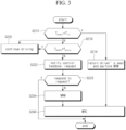
- FIG. 3 is a flowchart illustrating the operation of displaying a control handover request notification based on urgency in a Level 4 autonomous driving system according to various embodiments.
- the processor 130 may determine whether the event is an urgent event or a non-urgent event. According to an embodiment, when the event occurrence remaining time (T event ), which is the remaining time until the event occurs, is shorter than the minimum response time (T rti ), which is the minimum estimated time required for the user to perceive the current vehicle state and surrounding traffic and resume the DDT, the processor 130 may consider the event as an urgent event; when the event occurrence remaining time (T event ) is longer than the minimum response time (T rti ), the processor 130 may consider the event as a non-urgent event.
- T event the event occurrence remaining time
- T rti the minimum response time
- the event may be one that requires the handover of control from the autonomous driving system to the user.
- the event may include situations where the ODD boundary is uncertain but there is a potential for ODD deviation, such as planned ODD boundary approach events, sudden ODD boundary approach or deviation events, and changes in lighting conditions, rainfall, or snowfall.
- the event may also include situations where a minor malfunction does not yet require the execution of MRM but has the potential to degrade or worsen performance, or situations where a severe malfunction necessitates the execution of MRM.
- the autonomous driving system performs an MRM without user intervention and the vehicle reaches an MRC state, when the vehicle can still be driven by the user, this may be considered an event requiring control handover.
- the event may include situations where the user engages in non-driving related activities beyond the permissible limits of the autonomous driving system, such as falling into a deep sleep, or user conditions that make driving impossible, like cardiac arrest or intoxication.
- sudden ODD boundary approach or deviation events events where a severe malfunction necessitates MRM execution, events indicating a user's unresolvable condition during driving such as cardiac arrest or intoxication, and events where the autonomous driving system performs MRM without user intervention and the vehicle reaches an MRC state may be considered urgent events
- planned ODD boundary approach events events where the ODD boundary is uncertain but there is a risk of ODD deviation
- events where a minor malfunction does not yet require MRM but has the potential to degrade or worsen performance events where the user engages in non-driving-related activities within permissible limits, such as deep sleep, may be considered non-urgent events.
- the processor 130 may proceed to operation S214 to perform a minimal risk maneuver (MRM) while moving at least the driver's seat to a position predefined by the user.
- MRM minimal risk maneuver
- the processor 130 may move not only the driver's seat but also all seats in the vehicle to positions predefined by the user.
- the vehicle 100 may transition to the minimal risk condition (MRC) state in operation S240.
- MRC minimal risk condition
- the processor 130 may proceed to operation S218 to determine whether the event occurrence remaining time (T event ) is longer than the alarm time (T alarm ).
- the alarm time (T alarm ) may be a value calculated by adding, to the minimum response time (T rti ), the vehicle state change time required to bring the vehicle to a user-drivable state based on the vehicle state and the additional buffer time (T driver ) required until the user can perform driving operations based on the user state detected by the user state detection unit 111.
- the user state may include information about whether the user is asleep and gaze information. In detail, when the user is in a sleep state, the buffer time may be considerably longer, and the buffer time may increase further when the user's gaze is not directed forward.
- the vehicle state change time may include the seat adjustment time (T seat ) and/or the operation interface adjustment time.
- the seat adjustment time (T seat ) may refer to the time required to adjust the driver's seat from the state it was in while the user was not engaged in driving to a state that allows the user to drive.
- the state of the driver's seat that allows the user to drive may be the state the seat was in when the user was in control of the vehicle before the autonomous driving system took control.
- the adjustment of the driver's seat state includes not only two-dimensional and three-dimensional positional changes in the seat's up, down, left, right, front, and back directions, but also changes in the seat's rotation angle (where the angle is set to zero when the seat is adjusted for the user to drive) and changes in the backrest tilt, encompassing all alterations from the seat's state set for driving.
- the operation interface adjustment time may refer to the time required to transition the operation interface, such as the steering wheel, from a state the steering wheel was in while the user was not engaged in driving to a state that allows the user to drive. According to an embodiment, this time may also refer to the duration required to extend or deploy the operation interface, which was retracted during autonomous driving, to a position where the user can access and utilize it for driving.
- the operation interface may be in a different orientation or have undergone changes in its two-dimensional or three-dimensional position, such as moving up, down, left, right, forward, or backward, and in this case, the operation interface adjustment time refers to the time required to transition the operation interface from this altered state to a state where the user can access and utilize the operation interface for driving.
- the seat adjustment time and operation interface adjustment time may increase as the changes in the seat and operating interface deviate further from the normal state that allows the user to drive the vehicle.
- the longer duration between the operation interface adjustment time and seat adjustment time (T seat ) may be considered as the vehicle state change time.
- the vehicle state change time may be determined by adding the seat adjustment time (T seat ) and the operation interface adjustment time.
- the processor 130 may proceed to operation S220 to continue driving the vehicle based on the level 4 autonomous driving method (e.g., HMCS) without displaying a notification to the user. Meanwhile, the processor 130 may continuously determine whether the event occurrence remaining time (T event ) is still longer than the alarm time (T alarm ) in operation S218.
- the level 4 autonomous driving method e.g., HMCS
- the processor 130 may proceed to operation S222 to display a stage 1 control handover request notification to the user. That is, a processor 130 performing Level 4 autonomous driving, such as HMCS, may provide a control handover request notification to the user as early as the alarm time (T alarm ) before the event is expected to occur.
- HMCS Level 4 autonomous driving
- the processor 130 may determine in operation S223 whether the user responds to the handover request. When the user's response to the handover request is deemed sufficient, the processor 130 may terminate both the notification display and the Level 4 autonomous driving operation.
- the processor 130 may proceed to operation S234 to perform a minimal risk maneuver (MRM). As the processor 130 performs the minimal risk maneuver (MRM) in operation S234, the vehicle 100 may transition to the minimal risk condition (MRC) state in operation S240.
- MRM minimal risk maneuver
- the processor 130 may terminate both the notification display and the Level 4 autonomous driving operation.
- FIG. 4 is a flowchart illustrating the operation of displaying multi-stage notifications based on urgency and user response in a Level 4 autonomous driving system according to various embodiments.
- FIG. 4 illustrates an expanded version of the method depicted in FIG. 3 , with operations denoted by the same reference numbers performing the same functions. Additionally, FIG. 4 presents several extension options based on the method of FIG. 3 , and some or all of the proposed extension options may be applied.
- the processor 130 may determine whether the event is an urgent event or a non-urgent event. According to an embodiment, when the event occurrence remaining time (T event ), which is the remaining time until the event occurs, is shorter than the minimum response time (T rti ), which is the minimum estimated time required for the user to perceive the current vehicle state and surrounding traffic and resume the DDT, the processor 130 may consider the event as an urgent event; when the event occurrence remaining time (T event ) is longer than the minimum response time (T rti ), the processor 130 may consider the event as a non-urgent event.
- T event the event occurrence remaining time
- T rti the minimum response time
- the event may be one that requires the handover of control from the autonomous driving system to the user.
- the event may include situations where the ODD boundary is uncertain but there is a potential for ODD deviation, such as planned ODD boundary approach events, sudden ODD boundary approach or deviation events, and changes in lighting conditions, rainfall, or snowfall.
- the event may also include situations where a minor malfunction does not yet require the execution of MRM but has the potential to degrade or worsen performance, or situations where a severe malfunction necessitates the execution of MRM.
- the autonomous driving system performs an MRM without user intervention and the vehicle reaches an MRC state, when the vehicle can still be driven by the user, this may be considered an event requiring control handover.
- the event may include situations where the user engages in non-driving related activities beyond the permissible limits of the autonomous driving system, such as falling into a deep sleep, or user conditions that make driving impossible, like cardiac arrest or intoxication.
- sudden ODD boundary approach or deviation events events where a severe malfunction necessitates MRM execution, events indicating a user's unresolvable condition during driving such as cardiac arrest or intoxication, and events where the autonomous driving system performs MRM without user intervention and the vehicle reaches an MRC state may be considered urgent events
- planned ODD boundary approach events events where the ODD boundary is uncertain but there is a risk of ODD deviation
- events where a minor malfunction does not yet require MRM but has the potential to degrade or worsen performance events where the user engages in non-driving-related activities within permissible limits, such as deep sleep, may be considered non-urgent events.
- the processor 130 Upon determining in operation S210 that an urgent event has occurred, the processor 130 proceeds to operation S212 to determine the driving risk level.
- the driving risk level may be determined based on at least one of braking deceleration used during minimal risk maneuvers (MRM), steering torque, steering rate of change, expected vehicle yaw-rate change, vehicle stability, or risk level assessment values provided by the autonomous driving system.
- MRM minimal risk maneuvers
- the processor 130 Upon determining in operation S212 that the driving risk level is low or the driving risk level has a lower value than pre-determined value, the processor 130 proceeds to operation S214 to perform a minimal risk maneuver (MRM) while moving the driver's seat to a position predefined by the user.
- MRM minimal risk maneuver
- the processor 130 Upon determining in operation S212 that the driving risk level is high or the driving risk level has a higher value than or equal to the pre-determined value, the processor 130 proceeds to operation S216 to respond to the emergency event by adjusting the driver's seat to a position that protects the user and/or passengers in the event of a collision, while also performing a minimal risk maneuver (MRM). For example, the processor 130 may adjust the seat to a position that minimizes injury during a collision, taking into account the user's physical information obtained from the user state detection unit 111, the position of the airbags, and the current seat position.
- MRM minimal risk maneuver
- the vehicle 100 may transition to the minimal risk condition (MRC) state in operation S240.
- MRC minimal risk condition
- the processor 130 may proceed to operation S218 to determine whether the event occurrence remaining time (T event ) is longer than the alarm time (T alarm ).
- the alarm time (T alarm ) may be determined based on the user state and/or the vehicle state.
- the alarm time (T alarm ) may be a value calculated by adding, to the minimum response time (T rti ), the vehicle state change time required to bring the vehicle to a user-drivable state based on the vehicle state and the additional buffer time (T driver ) required until the user can perform driving operations based on the user state detected by the user state detection unit 111.
- the user state may include information about whether the user is asleep and gaze information.
- the buffer time may be considerably longer, and the buffer time may increase further when the user's gaze is not directed forward.
- the operation interface adjustment time may refer to the time required to transition the operation interface, such as the steering wheel, from a state the steering wheel was in while the user was not engaged in driving to a state that allows the user to drive. According to an embodiment, this time may also refer to the duration required to extend or deploy the operation interface, which was retracted during autonomous driving, to a position where the user can access and utilize it for driving.
- the operation interface may be in a different orientation or have undergone changes in its two-dimensional or three-dimensional position, such as moving up, down, left, right, forward, or backward, and in this case, the operation interface adjustment time refers to the time required to transition the operation interface from this altered state to a state where the user can access and utilize the operation interface for driving.
- the seat adjustment time and operation interface adjustment time may increase as the changes in the seat and operating interface deviate further from the normal state that allows the user to drive the vehicle.
- the longer duration between the operation interface adjustment time and seat adjustment time (T seat ) may be considered as the vehicle state change time.
- the vehicle state change time may be determined by adding the seat adjustment time (T seat ) and the operation interface adjustment time.
- the processor 130 may proceed to operation S220 to continue driving the vehicle based on the level 4 autonomous driving method (e.g., HMCS) without displaying a notification to the user. Meanwhile, the processor 130 may continuously determine whether the event occurrence remaining time (T event ) is still longer than the alarm time (T alarm ) in operation S218.
- the level 4 autonomous driving method e.g., HMCS
- the processor 130 may proceed to operation S224 to determine whether the event occurrence remaining time (T event ) is less than the sum of the minimum response time (T rti ) and the seat adjustment time (T seat ) .
- the processor 130 may monitor in operation S224 until the event occurrence remaining time (T event ) is less than the sum of the minimum response time (T rti ) and the seat adjustment time (T seat ), and upon the event occurrence remaining time (T event ) becoming less than the sum of the minimum response time (T rti ) and the seat adjustment time (T seat ), proceed to operation S226 to display a stage 2 control handover request notification to the user while moving the driver's seat to a position predefined by the user.
- the processor 130 may determine whether the event occurrence remaining time (T event ) is greater than the minimum response time (T rti ) . With reference to operations S224 and S226, in operation S228, the processor 130 may wait for the time required for the driver's seat to be adjusted to a position predefined by the user. Therefore, in operation S228, the processor 130 may also determine whether the driver's seat is in the position predefined by the user.
- the processor 130 may proceed to operation S230 to display a stage 3 control handover request notification.
- the processor 130 After displaying the stage 3 control handover request notification, the processor 130 proceeds to operation S232 to determine whether the event occurrence remaining time (T event ) is less than or equal to zero. Upon determining in operation S232 that the event occurrence remaining time (T event ) is less than or equal to zero, the processor 130 proceeds to operation S234 to perform a minimal risk maneuver (MRM). As the processor 130 performs the minimal risk maneuver (MRM) in operation S234, the vehicle 100 may transition to the minimal risk condition (MRC) state in operation S240.
- MRM minimal risk maneuver
- the processor 130 may display a stage 3 control handover request notification in operation S230 and immediately proceed to operation S234 to perform a minimal risk maneuver (MRM).
- MRM minimal risk maneuver
- the processor 130 may determine in operation S242 whether the vehicle is capable of continuing to drive. For example, the processor 130 may use information obtained from the sensor unit 110 to determine whether the vehicle is capable of only manual driving, both manual driving and autonomous driving, or is incapable of even manual driving.
- the processor 130 may proceed to operation S244 to request assistance through an emergency rescue system (e.g., E-call).
- an emergency rescue system e.g., E-call
- the processor 130 may proceed to operation S246 to display a stage 4 control handover request notification.
- the processor 130 may adjust the driver's seat to the state predefined by the user as a part of handling high-risk emergency events.
- the processor 130 may request external assistance through an emergency rescue system (e.g., E-call).
- an emergency rescue system e.g., E-call
- a system or processor 130 performing Level 4 autonomous driving goes through a total of four stages for non-urgent events, providing different alarms at each stage, and may, as needed, perform controls related to changing the driver's seat to a drivable state, extending/activating the operation interface, and other related adjustments.
- the processor 130 may display increasingly intense notifications for control handover as the stage progresses from stage 1 to stage 4, as shown in FIG. 4 .
- a stage 1 notification may use one or more types of outputs- visual, auditory, and tactile-to provide information about the occurrence and type of the event and the information necessary for control handover.
- a stage 2 notification may use two or more types of outputs-visual, auditory, and tactile-to provide information about the occurrence and type of the event and the information necessary for control handover, while also adjusting the driver's seat to a position that allows the user to drive, which was the state before the Level 4 autonomous driving system took over, or, when the user's control interface has been displaced, returning it to its original position.
- a stage 3 notification may use all methods of visual, auditory, and tactile outputs to provide information about the occurrence and type of the event and the information necessary for control handover.
- a stage 4 notification may provide information with the same intensity as a stage 3 notification or with a stronger intensity than a stage 3 notification.
- various embodiments relate to a method for providing notifications to a user when the user is required to take control of the vehicle in Level 4 autonomous driving. Since the user may not be involved in driving at all when Level 4 autonomous driving, which is a highly autonomous driving, the user is likely to be paying attention to something other than driving the vehicle. Therefore, there is a high probability that the user may not be aware of or respond immediately to the vehicle control handover notification sent from the Level 4 autonomous driving system. In this situation, the various embodiments proposed in this document suggest a method for providing notifications in stages from Stage 1 to Stage 4, considering the user's situation during Level 4 autonomous driving.
Landscapes
- Engineering & Computer Science (AREA)
- Automation & Control Theory (AREA)
- Transportation (AREA)
- Mechanical Engineering (AREA)
- Human Computer Interaction (AREA)
- Physics & Mathematics (AREA)
- Mathematical Physics (AREA)
- Aviation & Aerospace Engineering (AREA)
- Chemical & Material Sciences (AREA)
- Combustion & Propulsion (AREA)
- Traffic Control Systems (AREA)
- Control Of Driving Devices And Active Controlling Of Vehicle (AREA)
Abstract
Description
- This document relates to an autonomous vehicle and operating method thereof, and more particularly, to a method for providing an alarm for handover of driving control from the autonomous driving system to the user in a
Level 4 autonomous vehicle. - The Society of Automotive Engineers (SAE) categorizes the maturity of vehicle autonomous driving technology into industry standard levels ranging from 0 to 5. Among these,
Level 4 autonomous driving technology, referred to as high automation, is characterized by the automated driving system being fully responsible for vehicle operation within a specific operational design domain (ODD) without user or driver intervention. -
Level 4 autonomous systems monitor the driving environment and vehicle state in real-time, can perform all driving functions under everyday routes or predefined conditions, and do not require user intervention in driving. - However, in certain environments, such as heavy snowfall, or when the vehicle operates outside its ODD, the
Level 4 autonomous system needs to transfer the dynamic driving task (DDT) to the user. -
Level 4 autonomous driving technology is also referred to as the "Mind off" level because it should not require the user's attention, allowing the user of aLevel 4 autonomous vehicle to rely on the autonomous driving system for vehicle operation and engage in a variety of non-driving-related activities. Due to this, even when the autonomous system requests control handover through alarms, the user may need significant time to take over control. - Currently commercialized autonomous systems have a limited and standardized set of predefined request-to-intervene (RTI) scenarios, and their responses are also uniform. Furthermore, since
Level 4 autonomous systems have not yet been commercialized, there is no established definition for when and how to request control handover inLevel 4 autonomous systems. - The various embodiments of this document aim to provide a method for requesting the handover of driving control from the autonomous driving system to the user, based on a user monitoring system, considering the characteristics of a
Level 4 autonomous driving system. - The various embodiments of this document also aim to define the various conditions under which a request for the handover of driving control should be made in a
Level 4 autonomous driving system. - The technical objects of this document are not limited to the aforesaid, and other objects not described herein with can be clearly understood by those skilled in the art from the descriptions below.
- According to various embodiments of this document, a vehicle with autonomous driving capabilities may comprise at least one sensor configured to detect external environment of the vehicle, state of the vehicle, and state of a user, a processor configured to execute autonomous driving of the vehicle based on information obtained through the at least one sensor, and a controller configured to control the operation of the vehicle under the control of the processor, wherein the processor may determine whether the control of the vehicle needs to be handed over to the user based on an event occurring during autonomous driving of the vehicle, and provide the user with a notification indicating that the control of the vehicle needs to be handed over to the user, the notification being provided through multiple stages. This helps to prevent accidents and to increase passenger trust in the system by handling inevitable control handover events in a
Level 4 autonomous system situationally rather than uniformly. - According to an embodiment, the processor may detect an upcoming event, determine whether the control needs to be handed over based on the event, acquire an event occurrence remaining time until the event occurs when the control needs to be handed over, determine whether the event occurrence remaining time is greater than or equal to a first time, determine whether the event occurrence remaining time is greater than a second time when the event occurrence remaining time is greater than or equal to the first time, continue autonomous driving when the event occurrence remaining time is greater than the second time, and display a first-stage notification for control handover request when the event occurrence remaining time is less than the second time, wherein the second time is determined based on at least one of the state of the user and the state of the vehicle. Because the second time is determined based on at least one of the state of the user and the state of the vehicle, users will be able to perceive and respond to the control handover request within the necessary response time, even if the user is currently engaged in activities unrelated to vehicle operation. This is most advantageous e.g. in
Level 4 autonomous driving where the time taken for users to perceive the notification and resume the dynamic driving task (DDT) may be significantly longer compared toLevel 1 to 3 autonomous driving. - According to an embodiment, the second time may be calculated by adding, to the first time, a vehicle state change time needed to bring the vehicle to a state where the user is able to drive the vehicle based on the state of the vehicle, and buffer time required for the user to perform a driving operation based on the state of the user. This contributes to reliably and effectively preventing accidents and increasing passenger trust in the system.
- According to an embodiment, the buffer time may be configured to increase user's gaze deviates further from forward direction, and the vehicle state change time may be configured to increase as the seat or driving operation interface deviates more from a normal state allowing the user to drive the vehicle. Again, this contributes to reliably and effectively preventing accidents and increasing passenger trust in the system.
- According to an embodiment, the processor may execute a minimal risk maneuver to transition the vehicle to a minimal risk condition state based on the event occurrence remaining time being less than the first time. The first time is minimum expected time which is required for the user to recognize the current state of the vehicle and surrounding traffic and be able to drive the vehicle. Hence, the comparison between the first time and the event occurrence remaining time makes it possible to prevent accidents because the processor can start minimal risk maneuver before the notification for control handover request or without the notification for control handover request.
- According to an embodiment, the processor may calculate a driving risk level of the vehicle based on the event occurrence remaining time being less than the first time, move the driver's seat to a state predefined by the user based on the driving risk level being determined as low risk, and move the driver's seat to a state capable of protecting the user based on the driving risk level being determined as high risk. Such movement of the driver's seat makes it possible to prevent severe injury of user because predefined seat position is suitable location and direction for in-vehicle safety equipment. And driver's seat can be used as protective guard when the driving risk level is determined as high risk.
- According to an embodiment, the processor may display a second-stage notification for control handover request based on the event occurrence remaining time being less than a third time, and display a third-stage notification for control handover request based on the event occurrence remaining time being less than a fourth time, the first time and the fourth time being the same, the third time being longer than the fourth time, the second time being longer than the third time. Advantageously, repeated and/or diverse notification may draw the user's attention to current state of the vehicle and surrounding traffic. The third-stage notification can be a last call for handover request to a user because the fourth time is minimum expected time which is required for the user to recognize the current state of the vehicle and surrounding traffic and be able to drive the vehicle. Overall, this contributes to reliably and effectively preventing accidents and increasing passenger trust in the system.
- According to an embodiment, the processor may execute a minimal risk maneuver driving after fifth time since displaying the third-stage notification to transition the vehicle to a minimal risk condition state.
- According to an embodiment, the first time and the fourth time are minimum expected time required for the user to recognize the current state of the vehicle and surrounding traffic and be able to drive the vehicle, and the third time is the time obtained by subtracting the buffer time from the second time.
- According to an embodiment, the processor may move the driver's seat to the state predefined by the user while displaying the second-stage notification. Automatic adjustment of seat position and/or direction by the processor is advantageous because it can reduce time of preparation for user's driving and remind the user that urgent event or non-urgent event is coming.
- According to an embodiment, the vehicle state change time may comprise at least one of a seat adjustment time required to adjust the driver's seat from an altered state in which the user was not engaged in driving to a state that allows the user to drive, and an operation interface adjustment time required to adjust the operation interface to a state that allows the user to use.
- According to various embodiments of this document, a method for operating a vehicle with autonomous driving capabilities may comprise determining whether the control of the vehicle needs to be handed over to a user based on an event occurring during autonomous driving of the vehicle, and providing the user with a notification indicating that the control of the vehicle needs to be handed over to the user, the notification being provided through multiple stages.
- According to an embodiment, the determining of whether the control of the vehicle needs to be handed over may comprise detecting an upcoming event and determining whether the control needs to be handed over based on the event, and the providing the user with a notification may comprise acquiring an event occurrence remaining time until the event occurs when the control needs to be handed over, determining whether the event occurrence remaining time is greater than or equal to a first time, determining whether the event occurrence remaining time is greater than a second time when the event occurrence remaining time is greater than or equal to the first time, continuing autonomous driving based on the event occurrence remaining time being greater than the second time, and displaying a first-stage notification for control handover request based on the event occurrence remaining time being less than the second time, wherein the second time is determined based on at least one of the state of the user and the state of the vehicle. As a result, the method according to the invention may achieve the advantages described above and disclosed in this document.
- According to an embodiment, the second time may be calculated by adding, to the first time, a vehicle state change time needed to bring the vehicle to a state where the user is able to drive the vehicle based on the state of the vehicle, and the buffer time required for the user to perform a driving operation based on the state of the user.
- According to an embodiment, the state of the user may comprise gaze information and information on whether the user is asleep, and the state of the vehicle may include at least one of seat state information and driving operation interface state information.
- According to an embodiment, the buffer time may be configured to increase user's gaze deviates further from forward direction, and the vehicle state change time may be configured to increase as the seat or driving operation interface deviates more from a normal state allowing the user to drive the vehicle.
- According to an embodiment, the providing the user with a notification may comprise executing a minimal risk maneuver to transition the vehicle to a minimal risk condition state based on the event occurrence remaining time being less than the first time.
- According to an embodiment, the providing the user with a notification may comprise calculating a driving risk level of the vehicle based on the event occurrence remaining time being less than the first time, moving the driver's seat to a state predefined by the user based on the driving risk level being determined as low risk, and moving the driver's seat to a state capable of protecting the user based on the driving risk level being determined as high risk.
- According to an embodiment, the providing the user with a notification may comprise displaying a second-stage notification for control handover request based on the event occurrence remaining time being less than a third time, and displaying a third-stage notification for control handover request based on the event occurrence remaining time being less than a fourth time, wherein the first time and the fourth time are the same, the third time is longer than the fourth time, and the second time is longer than the third time.
- According to an embodiment, the first time and the fourth time are minimum expected time required for the user to recognize the current state of the vehicle and surrounding traffic and be able to drive the vehicle, and the third time is the time obtained by subtracting the buffer time from the second time.
- According to an embodiment, the providing of the notification may include moving the driver's seat to the state predefined by the user while displaying the second-stage notification.
- According to an embodiment, the vehicle state change time may include at least one of a seat adjustment time required to adjust the driver's seat from an altered state in which the user was not engaged in driving to a state that allows the user to drive, and an operation interface adjustment time required to adjust the operation interface to a state that allows the user to use.
-
-
FIG. 1 is a block diagram of a vehicle according to various embodiments of this document; -
FIG. 2 is a simplified state transition diagram of the HMCS, one of theLevel 4 autonomous driving technologies executed by the processor of a vehicle according to an embodiment; -
FIG. 3 is a flowchart illustrating the operation of displaying a control handover request notification based on urgency in aLevel 4 autonomous driving system according to various embodiments; and -
FIG. 4 is a flowchart illustrating the operation of displaying multi-stage notifications based on urgency and user response in aLevel 4 autonomous driving system according to various embodiments. - Hereinafter, descriptions are made of the embodiments of this document in detail with reference to accompanying drawings.
- The organization of this disclosure and its operational effects will be readily apparent from the detailed explanations provided below, facilitating a clear understanding. Before the detailed explanation in this document, it should be noted that the same reference numeral will be used for the same component whenever possible, even if displayed on different drawings, and that detailed descriptions of well-known components will be omitted to avoid obscuring the subject matter of this disclosure.
- Before proceeding with the detailed explanation in this document, the terms used herein may be defined as follows.
- A vehicle refers to one equipped with an automated driving system (ADS) capable of autonomous driving. For example, a vehicle may perform at least one of steering, acceleration, deceleration, lane changing, and stopping (or parking) without user intervention by the ADS. The ADS may include, for example, at least one of highly automated motorway chauffeur system (HMCS), pedestrian detection and collision mitigation system (PDCMS), lane change decision aid system (LCDAS), lane departure warning system (LDWS), adaptive cruise control (ACC), lane keeping assistance system (LKAS), road boundary departure prevention system (RBDPS), curve speed warning system (CSWS), forward vehicle collision warning system (FVCWS), and low speed following (LSF) .
- A user is a human who uses the vehicle and receive services from the autonomous driving system. According to an embodiment, all occupants of the vehicle may be users, and one of them may be the driver. The autonomous driving system may recognize the user seated in the designated driver's seat as the driver.
- Vehicle control authority refers to the authority to control at least one component and/or function of the vehicle. At least one function of the vehicle may include, for example, at least one of steering function, acceleration function, deceleration function (or braking function), lane change function, lane detection function, lateral control function, obstacle detection and distance sensing function, powertrain control function, safe area detection function, engine on/off function, power on/off function, and vehicle locking/unlocking function. The listed vehicle functions are examples provided for illustrative purposes, and the embodiments of this document are not limited thereto.
-
FIG. 1 is a block diagram of a vehicle according to various embodiments of this document, andFIG. 2 is a simplified state transition diagram of the HMCS, one of theLevel 4 autonomous driving technologies executed by the processor of a vehicle according to an embodiment; - The configuration of the vehicle depicted in
FIG. 1 is provided as an exemplary embodiment, and each component may be configured as one chip, one component, or one electronic circuit, or a combination of chips, components, and/or electronic circuits. According to an embodiment, some of the components shown inFIG. 1 may be separated into multiple components and configured as different chips, different components, or different electronic circuits, and some components may be combined to be configured as one chip, one component, or one electronic circuit. According to an embodiment, some components shown in 1 may be omitted, or other components not shown may be added. - With reference to
FIG. 1 , thevehicle 100 may include asensor unit 110, acontroller 120, aprocessor 130, auser interface 140, acommunication device 150, andmemory 160. - According to various embodiments, the
sensor unit 110 may acquire road information, information about objects around the vehicle (e.g., other vehicles, pedestrians, objects, curbs, guardrails, lanes, obstacles), and/or the vehicle's location information based on sensing data obtained from at least one sensor. Road information may include, for example, lane position, lane shape, lane color, lane type, number of lanes, presence of shoulders, or size of shoulders. Objects around the vehicle may include, for example, the position of objects, the size of objects, the shape of objects, the distance to objects, and the relative speed of objects. - According to an embodiment, the
sensor unit 110 may include at least one of a camera, light detection and ranging (LiDAR), radio detection and ranging (RADAR), an ultrasonic sensor, an infrared sensor, and a position measurement sensor. The listed sensors are provided as examples for illustrative purposes only, and the sensors included in thesensor unit 110 of this document are not limited thereto. The camera may capture images around the vehicle to generate image data, including lanes and/or surrounding objects in the front, rear, and/or sides of thevehicle 100. The LiDAR may use light (or laser) to generate information about objects located in the front, rear, and/or sides of thevehicle 100. The radar may use electromagnetic waves (or radio waves) to generate information about objects located in the front, rear, and/or sides of thevehicle 100. The ultrasonic sensor may use ultrasonic waves to generate information about objects located in the front, rear, and/or sides of thevehicle 100. The infrared sensor may use infrared to generate information about objects located in the front, rear, and/or sides of thevehicle 100. The position measurement sensor may measure the current position of the vehicle. The position measurement sensor may include at least one of a global positioning system (GPS) sensor, a differential global positioning system (DGPS) sensor, and a global navigation satellite system (GNSS) sensor. The position measurement sensor may generate location data of the vehicle based on signals generated by at least one of the GPS sensor, DGPS sensor, and GNSS sensor. - The
sensor unit 110 may include various subfunctional modules, such as a userstate detection unit 111, a vehiclestate detection unit 113, and an externalrecognition sensor unit 115. - The user
state detection unit 111 may detect the current status of the user. According to an embodiment, when there are a plurality of occupants in the vehicle, the userstate detection unit 111 may recognize all of occupants as users and monitor their statuses. Additionally, the userstate detection unit 111 may recognize the user seated in the driver's seat as the driver and monitor the driver's status more closely. For example, the userstate detection unit 111 may determine the presence or absence of the user in the driver's seat, detect whether the user is drowsy, and/or assess the level of fatigue the user is experiencing. Furthermore, the userstate detection unit 111 may determine the concentration level of the user's current behavior and whether the behavior is acceptable. For example, the userstate detection unit 111 may determine whether the user is concentrating on reading or playing a game, and whether the user is engaged in acceptable activities within the range that allows for an immediate takeover of driving control of the vehicle. The userstate detection unit 111 may also determine whether the user is capable of driving. For example, the userstate detection unit 111 may determine whether the user seated in the driver's seat is a licensed driver by identifying the user's biometric characteristics, and may also determine whether the user is intoxicated. In addition, the userstate detection unit 111 may also detect the user's physical information (e.g., height, weight, etc.). - According to an embodiment, the vehicle
state detection unit 113 may acquire internal vehicle state information using sensors, etc. For example, the vehiclestate detection unit 113 may detect normal operating information and/or fault status information for each component of the vehicle. In addition, the vehiclestate detection unit 113 may acquire the current status of the driver's seat and the status of the driver's seat before activating the autonomous driving system. The status of the driver's seat may include information such as seat position, seat rotation angle, and seat backrest tilt. Furthermore, the vehiclestate detection unit 113 may detect user input related to vehicle motion control, such as steering torque and acceleration or braking pedal inputs. - According to an embodiment, the external
recognition sensor unit 115 may detect operational design domain (ODD) information, such as whether the vehicle is within the ODD and approaching ODD boundaries, and recognize normal operation information and/or fault status information for each sensor. In addition, the externalrecognition sensor unit 115 may provide its own reliability information for the sensor output from thesensor unit 110. For example, the externalrecognition sensor unit 115 might provide lane detection reliability information, output variance information, and/or reflected wave intensity. - According to various embodiments, the
controller 120 may control the operation of at least one component of thevehicle 100 and/or at least one function of the vehicle under the control of theprocessor 130. At least one function may include, for example, steering function, acceleration function or longitudinal acceleration function, deceleration function or longitudinal deceleration function, brake function, lane change function, lane detection function, obstacle detection and distance detection function, lateral control function, powertrain control function, safe area detection function, engine on/off, power on/off, and at least one of locking/unlocking functions of the vehicle. - According to an embodiment, the
controller 120 may control the operation of at least one component and/or at least one function of thevehicle 100 for autonomous driving (e.g., autonomous driving according to HMCS) and/or minimal risk maneuver (MRM) under the control of theprocessor 130. For example, thecontroller 120 may control the operation of at least one of the steering function, acceleration function, deceleration function, lane change function, lane detection function, lateral control function, obstacle detection and distance detection function, powertrain control function, and safe area detection function for minimal risk maneuver. - According to an embodiment, the
controller 120 may include aseat control unit 121, an operationinterface control unit 123, and a vehiclemotion control unit 125. Theseat control unit 121, operationinterface control unit 123, and vehiclemotion control unit 125 may perform various tasks to notify the user of control handover in aLevel 4 autonomous driving system. For example, theseat control unit 121 may return the driver's seat to the driving position, and the operationinterface control unit 123 may control the operation interface to extend such that the user can operate the vehicle. - The vehicle
motion control unit 125 may control the vehicle's motion by controlling the vehicle's suspension, etc. - According to various embodiments, the user interface (UI) 140 may include various devices that provide information related to the
vehicle 100 in auditory, visual, and/or tactile manners. For example, theuser interface 140 may include haptic devices equipped in the displays, seats, or seatbelts, and speakers providing information through sound. The user interface (UI) 140 may provide the user of thevehicle 100 with various information related to the status of thevehicle 100 under the control of theprocessor 130. In addition, the user interface (UI) 140 may provide various notifications from the autonomous driving system to the user in visual, auditory, and/or tactile manners under the control of theprocessor 130. The various information related to the status of the vehicle may include at least one of information indicating the normal operation or malfunction of various components included in the vehicle and/or at least one function of the vehicle, and information indicating the driving status of the vehicle. - According to various embodiments, the
communication device 150 may communicate with external devices of thevehicle 100. According to an embodiment, thecommunication device 150 may receive data from the outside of thevehicle 100 or transmit data the outside of thevehicle 100 under the control of theprocessor 130. For example, thecommunication device 150 may perform communication using wireless or wired communication protocols. - According to various embodiments, the
memory 160 may store autonomous driving programs implemented by the autonomous driving system or theprocessor 130. According to an embodiment, thememory 160 may store a program for implementing HMCS, and theprocessor 130 may read the corresponding program from thememory 160 to implement the HMCS autonomous driving function. - According to various embodiments, the
processor 130 may control the overall operation of thevehicle 100. In an embodiment, theprocessor 130 may include an electrical control unit (ECU) capable of integratively controlling components within thevehicle 100. For example, theprocessor 130 may include a central processing unit (CPU) or micro controller unit (MCU) capable of performing computational tasks. - According to various embodiments, the
processor 130 may activate automated driving system (ADS) upon occurrence of predetermined events, thereby controlling components within thevehicle 100 to enable autonomous driving. The predetermined events may occur when autonomous driving of the vehicle is requested, when vehicle control authority is delegated by the user, or when conditions specified by the user and/or designer are satisfied. - According to various embodiments, the
processor 130 may determine whether autonomous driving is possible based on at least one of the vehicle state information and surrounding environmental information during autonomous driving. In situations where normal autonomous driving is not possible, theprocessor 130 may control the vehicle to come to a stop by executing a minimum risk maneuver (MRM). - According to an embodiment, the
processor 130 may execute highly automated motorway chauffeur systems (HMCS), aLevel 4 autonomous driving technology, as illustrated inFIG. 2 . HMCS is one of theLevel 4 autonomous driving technology standards, designed to enable autonomous vehicles to perform the complete dynamic driving task (DDT) on access-controlled highways that meet the operational design domain (ODD) constraints. - With reference to
FIG. 2 , theprocessor 130 may start in the HMCS offstate 210. Since HMCS is aLevel 4 autonomous driving technology specifically for driving on access-controlled highways, it may remain off and not be activated on regular roads. Theprocessor 130 may remain in the HMCS off state unless the vehicle approaches the operational design domain defined for HMCS. - The
processor 130 may transition from the HMCS offstate 210 to theHMCS standby state 220 upon recognizing that thevehicle 100 is passing through a highway toll gate entrance, the driving conditions satisfy the ODD defined for HMCS, or based on user input. - The
processor 130 may transition from theHMCS standby state 220 to the HMCSactive state 230 when predetermined conditions are met. In the HMCSactive state 230, theprocessor 130 may perform autonomous driving according to the methods defined in HMCS. - In the HMCS
active state 230, theprocessor 130 may operate in either the coupledmode 231 or the decoupledmode 233 while carrying out normal vehicle driving operations. Here, coupledmode 231 is a mode where user input is for vehicle operation is possible and the user input may affect the vehicle operation.Decoupled mode 233 is a mode where the user input does not affect the vehicle operation. For example, in decoupledmode 233, even when the user presses the accelerator or brake, the vehicle's operation may not change accordingly. Various methods may be used to implement decoupledmode 233. - While controlling the vehicle normally based on HMCS autonomous driving technology, the
processor 130 may operate in either coupledmode 231 or decoupledmode 233, and may switch from coupledmode 231 to decoupledmode 233 when condition A is met, or from decoupledmode 233 to coupledmode 231 when condition B is met. - According to an embodiment, the
processor 130 may automatically transition from coupledmode 231 to decoupledmode 233 without user consent, but requires user approval to switch from decoupledmode 233 to coupledmode 231. That is, theprocessor 130 may switch from decoupledmode 233 to coupledmode 231 only when a user or one of the users is in a position capable of driving and has approved the transition. - According to another embodiment, the
processor 130 may perform transitions only after obtaining user approval, both when transitioning from coupledmode 231 to decoupledmode 233 and when transitioning from decoupledmode 233 to coupledmode 231. - The
processor 130 may provide an alarm to the user regarding the transition when switching from decoupledmode 233 to coupledmode 231 or from coupledmode 231 to decoupledmode 233. Additionally, when user approval is required for the transition, theprocessor 130 may display a message requesting approval for the transition using theuser interface 140 or by using other components or methods. - In the HMCS
active state 230, when the conditions for activating minimal risk maneuver (MRM) are met, theprocessor 130 may perform MRM as denoted byreference number 235 to bring the vehicle to a minimal risk condition (MRC) state. Here, the MRC state may be a stationary state. In this state, HMCS may transition from the HMCSactive state 230 to the HMCS offstate 210. - The minimal risk maneuver (MRM) performed by the
processor 130 as denoted byreference numeral 235 may be carried out as follows. The following operation may be performed in parallel with the HMCS autonomous driving operation of theprocessor 130, and when the vehicle is brought to the minimal risk condition (MRC) state due to the MRM execution as denoted byreference number 235, the HMCS may transition from the HMCS active state to the HMCS offstate 210. - According to an embodiment, the
processor 130 may determine whether the functions required for autonomous driving are operating normally, based on the vehicle state information. The functions necessary for autonomous driving may include at least one of lane detection, lane change, lateral control, deceleration (or brake control), acceleration control, powertrain control, safe area detection, and obstacle detection and distance sensing. Theprocessor 130 may determine that normal autonomous driving is not possible when at least one of the functions necessary for autonomous driving cannot operate normally. - According to an embodiment, the
processor 130 may determine whether the vehicle state is suitable for normal operating conditions based on the vehicle state information. For example, theprocessor 130 may determine whether the mechanical status information of the vehicle (e.g., tire pressure information or engine overheating information) meets the requirements of normal operating conditions. Upon detecting that the status of the vehicle does not meet the requirements of normal operating conditions, theprocessor 130 may determine that normal autonomous driving is impossible. For example, when it is found that the vehicle cannot operate normally due to tire pressure issues or engine overheating, theprocessor 130 may determine that normal autonomous driving is not possible. - According to an embodiment, the
processor 130 may determine whether the surrounding environment of the vehicle is suitable for the basic operational design domain of autonomous driving based on at least part of surrounding environment information. The operational design domain represents the conditions under which autonomous driving operates effectively. Upon detecting that the surrounding environmental information does not meet the operational design domain, theprocessor 130 may determine that normal autonomous driving is impossible. - According to various embodiments, when normal autonomous driving is not possible, the
processor 130 may determine that a minimal risk maneuver is required to minimize the risk of an accident. When a minimal risk maneuver is needed, theprocessor 130 may select one of a plurality of minimal risk maneuver strategies and execute the maneuver. For example, the minimal risk maneuver strategies may include the traffic lane stop strategy and the load shoulders stop strategy. - The traffic lane stop strategy may include straight stop and in-lane stop, while the road shoulders stop strategy may include half-shoulder stop and full-shoulder stop.
- Straight stop is a type of stopping where only longitudinal deceleration control is used, and no lateral control is involved. For example, a straight stop may be performed in situations where lane detection is not possible or where lateral control is not possible due to a fault in the actuators. During a straight stop, acceleration control and lane change are prohibited or impossible, and detecting potential stopping positions outside the lane may be unnecessary. Here, detecting potential stopping locations outside traffic lane may refer to the function of detecting the positions of safe areas located outside traffic lanes, such as shoulders or rest areas.
- In-lane stop is a type of stopping where the vehicle comes to a stop within the boundaries of the lane the vehicle was traveling in. For example, an in-lane stop may refer to a type of stopping where the vehicle halts within the boundaries of the lane the vehicle was driving in using lateral control and/or deceleration control. The lane the vehicle was driving in may refer to the lane the vehicle was traveling in at the point when the need for minimal risk maneuvering is determined. During an in-lane stop, acceleration control and lane change are prohibited, and the lane-outside potential stopping position detection function may be unnecessary.
- Half-shoulder stop is a type of stopping where the vehicle comes to a stop with part of the vehicle on the shoulder of the road, while full-shoulder stop is a type of stopping where the entire vehicle comes to a stop on the shoulder of the road. During both half-shoulder and full-shoulder stops, lateral control, deceleration control, lane change, and lane-outside potential stopping position detection functions the lane may be used, and acceleration control may be employed only to maintain the current speed.
- With reference to
FIG. 2 , in the HMCSactive state 230, when the conditions for handover of vehicle control to the user are met, theprocessor 130 may display a message or notification to the user to resume the dynamic driving task (DDT) through various methods, as denoted byreference numeral 237. Theprocessor 130 may then transition from the HMCSactive state 230 to theHMCS standby state 220 when the user resumes the DDT. - Currently, standards for HMCS-related technologies are still in the early development stages, and there are no established norms for displaying notifications to the user as denoted by
reference number 237. However, inLevel 4 autonomous driving, users are likely to engage in activities unrelated to vehicle operation, and the time taken for users to perceive the notification and resume the DDT may be significantly longer compared toLevel 1 to 3 autonomous driving. Therefore, this document proposes a method for displaying notifications to ensure that users can perceive and respond to the control handover request within the necessary response time. -
FIG. 3 is a flowchart illustrating the operation of displaying a control handover request notification based on urgency in aLevel 4 autonomous driving system according to various embodiments; and - With reference to
FIG. 3 , in operation S210, upon recognizing that an event (e.g., collision with a vehicle in front) will occur, theprocessor 130 may determine whether the event is an urgent event or a non-urgent event. According to an embodiment, when the event occurrence remaining time (Tevent), which is the remaining time until the event occurs, is shorter than the minimum response time (Trti), which is the minimum estimated time required for the user to perceive the current vehicle state and surrounding traffic and resume the DDT, theprocessor 130 may consider the event as an urgent event; when the event occurrence remaining time (Tevent) is longer than the minimum response time (Trti), theprocessor 130 may consider the event as a non-urgent event. - In particular, the event may be one that requires the handover of control from the autonomous driving system to the user. The event may include situations where the ODD boundary is uncertain but there is a potential for ODD deviation, such as planned ODD boundary approach events, sudden ODD boundary approach or deviation events, and changes in lighting conditions, rainfall, or snowfall. The event may also include situations where a minor malfunction does not yet require the execution of MRM but has the potential to degrade or worsen performance, or situations where a severe malfunction necessitates the execution of MRM. Additionally, even if the autonomous driving system performs an MRM without user intervention and the vehicle reaches an MRC state, when the vehicle can still be driven by the user, this may be considered an event requiring control handover. Furthermore, the event may include situations where the user engages in non-driving related activities beyond the permissible limits of the autonomous driving system, such as falling into a deep sleep, or user conditions that make driving impossible, like cardiac arrest or intoxication.
- Among the aforementioned events, sudden ODD boundary approach or deviation events, events where a severe malfunction necessitates MRM execution, events indicating a user's unresolvable condition during driving such as cardiac arrest or intoxication, and events where the autonomous driving system performs MRM without user intervention and the vehicle reaches an MRC state may be considered urgent events, whereas planned ODD boundary approach events, events where the ODD boundary is uncertain but there is a risk of ODD deviation, events where a minor malfunction does not yet require MRM but has the potential to degrade or worsen performance, and events where the user engages in non-driving-related activities within permissible limits, such as deep sleep, may be considered non-urgent events.
- In operation S210, upon determining that an urgent event has occurred, the
processor 130 may proceed to operation S214 to perform a minimal risk maneuver (MRM) while moving at least the driver's seat to a position predefined by the user. According to an embodiment, in operation S214, theprocessor 130 may move not only the driver's seat but also all seats in the vehicle to positions predefined by the user. - In the case of an urgent event, as the
processor 130 performs the MRM in operation S214, thevehicle 100 may transition to the minimal risk condition (MRC) state in operation S240. - Upon determining in operation S210 that an urgent event has not occurred, the
processor 130 may proceed to operation S218 to determine whether the event occurrence remaining time (Tevent) is longer than the alarm time (Talarm). Here, the alarm time (Talarm) may be a value calculated by adding, to the minimum response time (Trti), the vehicle state change time required to bring the vehicle to a user-drivable state based on the vehicle state and the additional buffer time (Tdriver) required until the user can perform driving operations based on the user state detected by the userstate detection unit 111. Here, the user state may include information about whether the user is asleep and gaze information. In detail, when the user is in a sleep state, the buffer time may be considerably longer, and the buffer time may increase further when the user's gaze is not directed forward. - According to an embodiment, the vehicle state change time may include the seat adjustment time (Tseat) and/or the operation interface adjustment time. The seat adjustment time (Tseat) may refer to the time required to adjust the driver's seat from the state it was in while the user was not engaged in driving to a state that allows the user to drive. Here, the state of the driver's seat that allows the user to drive may be the state the seat was in when the user was in control of the vehicle before the autonomous driving system took control. Therefore, the adjustment of the driver's seat state includes not only two-dimensional and three-dimensional positional changes in the seat's up, down, left, right, front, and back directions, but also changes in the seat's rotation angle (where the angle is set to zero when the seat is adjusted for the user to drive) and changes in the backrest tilt, encompassing all alterations from the seat's state set for driving.
- The operation interface adjustment time may refer to the time required to transition the operation interface, such as the steering wheel, from a state the steering wheel was in while the user was not engaged in driving to a state that allows the user to drive. According to an embodiment, this time may also refer to the duration required to extend or deploy the operation interface, which was retracted during autonomous driving, to a position where the user can access and utilize it for driving. According to another embodiment, even if being not retracted, the operation interface may be in a different orientation or have undergone changes in its two-dimensional or three-dimensional position, such as moving up, down, left, right, forward, or backward, and in this case, the operation interface adjustment time refers to the time required to transition the operation interface from this altered state to a state where the user can access and utilize the operation interface for driving. The seat adjustment time and operation interface adjustment time may increase as the changes in the seat and operating interface deviate further from the normal state that allows the user to drive the vehicle.
- According to an embodiment, when the adjustment of the operation interface and seat occurs simultaneously, the longer duration between the operation interface adjustment time and seat adjustment time (Tseat) may be considered as the vehicle state change time. According to another embodiment, when the operation interface adjustment and seat adjustment are performed sequentially, the vehicle state change time may be determined by adding the seat adjustment time (Tseat) and the operation interface adjustment time.
- In operation S218, when the event occurrence remaining time (Tevent) is longer than the alarm time (Taiarm), the
processor 130 may proceed to operation S220 to continue driving the vehicle based on thelevel 4 autonomous driving method (e.g., HMCS) without displaying a notification to the user. Meanwhile, theprocessor 130 may continuously determine whether the event occurrence remaining time (Tevent) is still longer than the alarm time (Talarm) in operation S218. - In operation S218, when the event occurrence remaining time (Tevent) becomes shorter than the alarm time (Taiarm), the
processor 130 may proceed to operation S222 to display astage 1 control handover request notification to the user. That is, aprocessor 130performing Level 4 autonomous driving, such as HMCS, may provide a control handover request notification to the user as early as the alarm time (Talarm) before the event is expected to occur. - After displaying the notification, the
processor 130 may determine in operation S223 whether the user responds to the handover request. When the user's response to the handover request is deemed sufficient, theprocessor 130 may terminate both the notification display and theLevel 4 autonomous driving operation. - After the control hand over request notification is displayed, when the user does not respond to the control handover request, or the response is deemed insufficient in operation S223, the
processor 130 may proceed to operation S234 to perform a minimal risk maneuver (MRM). As theprocessor 130 performs the minimal risk maneuver (MRM) in operation S234, thevehicle 100 may transition to the minimal risk condition (MRC) state in operation S240. - Once the
vehicle 100 transitions to the minimal risk condition (MRC) state through the minimal risk maneuver (MRM), theprocessor 130 may terminate both the notification display and theLevel 4 autonomous driving operation. -
FIG. 4 is a flowchart illustrating the operation of displaying multi-stage notifications based on urgency and user response in aLevel 4 autonomous driving system according to various embodiments. -
FIG. 4 illustrates an expanded version of the method depicted inFIG. 3 , with operations denoted by the same reference numbers performing the same functions. Additionally,FIG. 4 presents several extension options based on the method ofFIG. 3 , and some or all of the proposed extension options may be applied. - With reference to
FIG. 4 , upon recognizing in operation S210 that an event (e.g., collision with a vehicle in front) will occur, theprocessor 130 may determine whether the event is an urgent event or a non-urgent event. According to an embodiment, when the event occurrence remaining time (Tevent), which is the remaining time until the event occurs, is shorter than the minimum response time (Trti), which is the minimum estimated time required for the user to perceive the current vehicle state and surrounding traffic and resume the DDT, theprocessor 130 may consider the event as an urgent event; when the event occurrence remaining time (Tevent) is longer than the minimum response time (Trti), theprocessor 130 may consider the event as a non-urgent event. - In particular, the event may be one that requires the handover of control from the autonomous driving system to the user. The event may include situations where the ODD boundary is uncertain but there is a potential for ODD deviation, such as planned ODD boundary approach events, sudden ODD boundary approach or deviation events, and changes in lighting conditions, rainfall, or snowfall. The event may also include situations where a minor malfunction does not yet require the execution of MRM but has the potential to degrade or worsen performance, or situations where a severe malfunction necessitates the execution of MRM. Additionally, even if the autonomous driving system performs an MRM without user intervention and the vehicle reaches an MRC state, when the vehicle can still be driven by the user, this may be considered an event requiring control handover. Furthermore, the event may include situations where the user engages in non-driving related activities beyond the permissible limits of the autonomous driving system, such as falling into a deep sleep, or user conditions that make driving impossible, like cardiac arrest or intoxication.
- Among the aforementioned events, sudden ODD boundary approach or deviation events, events where a severe malfunction necessitates MRM execution, events indicating a user's unresolvable condition during driving such as cardiac arrest or intoxication, and events where the autonomous driving system performs MRM without user intervention and the vehicle reaches an MRC state may be considered urgent events, whereas planned ODD boundary approach events, events where the ODD boundary is uncertain but there is a risk of ODD deviation, events where a minor malfunction does not yet require MRM but has the potential to degrade or worsen performance, and events where the user engages in non-driving-related activities within permissible limits, such as deep sleep, may be considered non-urgent events.
- Upon determining in operation S210 that an urgent event has occurred, the
processor 130 proceeds to operation S212 to determine the driving risk level. The driving risk level may be determined based on at least one of braking deceleration used during minimal risk maneuvers (MRM), steering torque, steering rate of change, expected vehicle yaw-rate change, vehicle stability, or risk level assessment values provided by the autonomous driving system. - Upon determining in operation S212 that the driving risk level is low or the driving risk level has a lower value than pre-determined value, the
processor 130 proceeds to operation S214 to perform a minimal risk maneuver (MRM) while moving the driver's seat to a position predefined by the user. - Upon determining in operation S212 that the driving risk level is high or the driving risk level has a higher value than or equal to the pre-determined value, the
processor 130 proceeds to operation S216 to respond to the emergency event by adjusting the driver's seat to a position that protects the user and/or passengers in the event of a collision, while also performing a minimal risk maneuver (MRM). For example, theprocessor 130 may adjust the seat to a position that minimizes injury during a collision, taking into account the user's physical information obtained from the userstate detection unit 111, the position of the airbags, and the current seat position. - In the case of an urgent event, as the
processor 130 performs the MRM in operation S214 or S216, thevehicle 100 may transition to the minimal risk condition (MRC) state in operation S240. - Upon determining in operation S210 that an urgent event has not occurred, the
processor 130 may proceed to operation S218 to determine whether the event occurrence remaining time (Tevent) is longer than the alarm time (Talarm). Here, the alarm time (Talarm) may be determined based on the user state and/or the vehicle state. - According to an embodiment, the alarm time (Talarm) may be a value calculated by adding, to the minimum response time (Trti), the vehicle state change time required to bring the vehicle to a user-drivable state based on the vehicle state and the additional buffer time (Tdriver) required until the user can perform driving operations based on the user state detected by the user
state detection unit 111. Here, the user state may include information about whether the user is asleep and gaze information. In detail, when the user is in a sleep state, the buffer time may be considerably longer, and the buffer time may increase further when the user's gaze is not directed forward. - According to an embodiment, the vehicle state change time may include the seat adjustment time (Tseat) and/or the operation interface adjustment time. The seat adjustment time (Tseat) may refer to the time required to adjust the driver's seat from the state it was in while the user was not engaged in driving to a state that allows the user to drive. Here, the state of the driver's seat that allows the user to drive may be the state the seat was in when the user was in control of the vehicle before the autonomous driving system took control. Therefore, the adjustment of the driver's seat state includes not only two-dimensional and three-dimensional positional changes in the seat's up, down, left, right, front, and back directions, but also changes in the seat's rotation angle (where the angle is set to zero when the seat is adjusted for the user to drive) and changes in the backrest tilt, encompassing all alterations from the seat's state set for driving.
- The operation interface adjustment time may refer to the time required to transition the operation interface, such as the steering wheel, from a state the steering wheel was in while the user was not engaged in driving to a state that allows the user to drive. According to an embodiment, this time may also refer to the duration required to extend or deploy the operation interface, which was retracted during autonomous driving, to a position where the user can access and utilize it for driving. According to another embodiment, even if being not retracted, the operation interface may be in a different orientation or have undergone changes in its two-dimensional or three-dimensional position, such as moving up, down, left, right, forward, or backward, and in this case, the operation interface adjustment time refers to the time required to transition the operation interface from this altered state to a state where the user can access and utilize the operation interface for driving. The seat adjustment time and operation interface adjustment time may increase as the changes in the seat and operating interface deviate further from the normal state that allows the user to drive the vehicle.
- According to an embodiment, when the adjustment of the operation interface and seat occurs simultaneously, the longer duration between the operation interface adjustment time and seat adjustment time (Tseat) may be considered as the vehicle state change time. According to another embodiment, when the operation interface adjustment and seat adjustment are performed sequentially, the vehicle state change time may be determined by adding the seat adjustment time (Tseat) and the operation interface adjustment time.
- In operation S218, when the event occurrence remaining time (Tevent) is longer than the alarm time (Taiarm), the
processor 130 may proceed to operation S220 to continue driving the vehicle based on thelevel 4 autonomous driving method (e.g., HMCS) without displaying a notification to the user. Meanwhile, theprocessor 130 may continuously determine whether the event occurrence remaining time (Tevent) is still longer than the alarm time (Talarm) in operation S218. - In operation S218, when the event occurrence remaining time (Tevent) becomes shorter than the alarm time (Taiarm), the
processor 130 may proceed to operation S222 to display astage 1 control handover request notification to the user. That is, aprocessor 130performing Level 4 autonomous driving, such as HMCS, may provide an initial handover request notification to the user as early as the alarm time (Talarm) before the event is expected to occur. - After displaying the initial notification, the
processor 130 may proceed to operation S224 to determine whether the event occurrence remaining time (Tevent) is less than the sum of the minimum response time (Trti) and the seat adjustment time (Tseat) . Theprocessor 130 may monitor in operation S224 until the event occurrence remaining time (Tevent) is less than the sum of the minimum response time (Trti) and the seat adjustment time (Tseat), and upon the event occurrence remaining time (Tevent) becoming less than the sum of the minimum response time (Trti) and the seat adjustment time (Tseat), proceed to operation S226 to display a stage 2 control handover request notification to the user while moving the driver's seat to a position predefined by the user. - In operation S228, the
processor 130 may determine whether the event occurrence remaining time (Tevent) is greater than the minimum response time (Trti) . With reference to operations S224 and S226, in operation S228, theprocessor 130 may wait for the time required for the driver's seat to be adjusted to a position predefined by the user. Therefore, in operation S228, theprocessor 130 may also determine whether the driver's seat is in the position predefined by the user. - Upon determining in operation S228 that the event occurrence remaining time (Tevent) is less than the minimum response time (Trti), the
processor 130 may proceed to operation S230 to display astage 3 control handover request notification. - After displaying the
stage 3 control handover request notification, theprocessor 130 proceeds to operation S232 to determine whether the event occurrence remaining time (Tevent) is less than or equal to zero. Upon determining in operation S232 that the event occurrence remaining time (Tevent) is less than or equal to zero, theprocessor 130 proceeds to operation S234 to perform a minimal risk maneuver (MRM). As theprocessor 130 performs the minimal risk maneuver (MRM) in operation S234, thevehicle 100 may transition to the minimal risk condition (MRC) state in operation S240. - According to another embodiment, when the
processor 130 determines in operation S228 that the event occurrence remaining time (Tevent) is less than the minimum response time (Trti), indicating a possible inability to respond to the event, theprocessor 130 may display astage 3 control handover request notification in operation S230 and immediately proceed to operation S234 to perform a minimal risk maneuver (MRM). - Once the
vehicle 100 transitions to the minimal risk condition (MRC) state through the minimal risk maneuver (MRM), theprocessor 130 may determine in operation S242 whether the vehicle is capable of continuing to drive. For example, theprocessor 130 may use information obtained from thesensor unit 110 to determine whether the vehicle is capable of only manual driving, both manual driving and autonomous driving, or is incapable of even manual driving. - Upon determining in operation S242 that even manual driving by the user is not possible, the
processor 130 may proceed to operation S244 to request assistance through an emergency rescue system (e.g., E-call). - Upon determining in operation S243 that either manual or autonomous driving is possible, the
processor 130 may proceed to operation S246 to display astage 4 control handover request notification. In this case, when the driver's seat is not in the state predefined by the user, theprocessor 130 may adjust the driver's seat to the state predefined by the user as a part of handling high-risk emergency events. - According to an embodiment, if the control handover is not completed within a predefined time after the
stage 4 control handover request notification, theprocessor 130 may request external assistance through an emergency rescue system (e.g., E-call). - According to the flowchart of
FIG. 4 , a system orprocessor 130performing Level 4 autonomous driving goes through a total of four stages for non-urgent events, providing different alarms at each stage, and may, as needed, perform controls related to changing the driver's seat to a drivable state, extending/activating the operation interface, and other related adjustments. - According to an embodiment, the
processor 130 may display increasingly intense notifications for control handover as the stage progresses fromstage 1 tostage 4, as shown inFIG. 4 . - For example, a
stage 1 notification may use one or more types of outputs- visual, auditory, and tactile-to provide information about the occurrence and type of the event and the information necessary for control handover. A stage 2 notification may use two or more types of outputs-visual, auditory, and tactile-to provide information about the occurrence and type of the event and the information necessary for control handover, while also adjusting the driver's seat to a position that allows the user to drive, which was the state before theLevel 4 autonomous driving system took over, or, when the user's control interface has been displaced, returning it to its original position. Astage 3 notification may use all methods of visual, auditory, and tactile outputs to provide information about the occurrence and type of the event and the information necessary for control handover. Astage 4 notification may provide information with the same intensity as astage 3 notification or with a stronger intensity than astage 3 notification. - Additionally, when the user takes control during the operations according to the flowchart of
FIG. 4 , the procedure immediately terminates, and the method shown inFIG. 4 is also concluded. - As described above, various embodiments relate to a method for providing notifications to a user when the user is required to take control of the vehicle in
Level 4 autonomous driving. Since the user may not be involved in driving at all whenLevel 4 autonomous driving, which is a highly autonomous driving, the user is likely to be paying attention to something other than driving the vehicle. Therefore, there is a high probability that the user may not be aware of or respond immediately to the vehicle control handover notification sent from theLevel 4 autonomous driving system. In this situation, the various embodiments proposed in this document suggest a method for providing notifications in stages fromStage 1 toStage 4, considering the user's situation duringLevel 4 autonomous driving. - According to various embodiments of this document, it is advantageous to prevent accidents and increase passenger trust in the system by handling inevitable control handover events in a
Level 4 autonomous system situationally rather than uniformly.
Claims (15)
- A vehicle with autonomous driving capabilities, the vehicle comprising:at least one sensor configured to detect external environment of the vehicle, state of the vehicle, and state of a user;a processor configured to execute autonomous driving of the vehicle based on information obtained through the at least one sensor; anda controller configured to control the operation of the vehicle under the control of the processor,wherein the processor is configured to:determine whether the control of the vehicle needs to be handed over to the user based on an event occurring during autonomous driving of the vehicle, andprovide the user with a notification indicating that the control of the vehicle needs to be handed over to the user.
- The vehicle of claim 1, wherein the processor is further configured to:detect an upcoming event,determine whether the control needs to be handed over based on the event,acquire an event occurrence remaining time until the event occurs when the control needs to be handed over,determine whether the event occurrence remaining time is greater than or equal to a first time,determine whether the event occurrence remaining time is greater than a second time when the event occurrence remaining time is greater than or equal to the first time,continue autonomous driving when the event occurrence remaining time is greater than the second time, anddisplay a first-stage notification for control handover request when the event occurrence remaining time is less than the second time,wherein the second time is determined based on at least one of the state of the user and the state of the vehicle.
- The vehicle of claim 2, wherein the second time is calculated by adding, to the first time, a vehicle state change time needed to bring the vehicle to a state where the user is able to drive the vehicle based on the state of the vehicle, and buffer time required for the user to perform a driving operation based on the state of the user.
- The vehicle of claim 2 or 3, wherein the state of the user comprises gaze information and information on whether the user is asleep, and the state of the vehicle comprises at least one of seat state information and driving operation interface state information.
- The vehicle of claim 3 or 4, wherein the buffer time is configured to increase user's gaze deviates further from forward direction, and the vehicle state change time is configured to increase as the seat or driving operation interface deviates more from a normal state allowing the user to drive the vehicle.
- The vehicle of any one of claims 2 to 5, wherein the processor is configured to execute a minimal risk maneuver to transition the vehicle to a minimal risk condition state based on the event occurrence remaining time being less than the first time, wherein the processor is preferably configured to:calculate a driving risk level of the vehicle based on the event occurrence remaining time being less than the first time,move the driver's seat to a state predefined by the user based on the driving risk level being determined as low risk, andmove the driver's seat to a state capable of protecting the user based on the driving risk level being determined as high risk.
- The vehicle of any one of claims 3 to 6, wherein the processor is configured to:display a second-stage notification for control handover request based on the event occurrence remaining time being less than a third time, anddisplay a third-stage notification for control handover request based on the event occurrence remaining time being less than a fourth time,wherein the first time and the fourth time is the same, the third time is longer than the fourth time, and the second time is longer than the third time.
- The vehicle of claim 7, wherein the first time and the fourth time are minimum expected time required for the user to recognize the current state of the vehicle and surrounding traffic and be able to drive the vehicle, and the third time is the time obtained by subtracting the buffer time from the second time.
- The vehicle of claim 7 or 8, wherein the processor is configured to move the driver's seat to the state predefined by the user while displaying the second-stage notification.
- The vehicle of any one of claims 3 to 9, wherein the vehicle state change time comprises at least one of a seat adjustment time required to adjust the driver's seat from an altered state in which the user was not engaged in driving to a state that allows the user to drive, and an operation interface adjustment time required to adjust the operation interface to a state that allows the user to use.
- A method for operating a vehicle with autonomous driving capabilities, the method comprising:determining whether the control of the vehicle needs to be handed over to a user based on an event occurring during autonomous driving of the vehicle; andproviding the user with a notification indicating that the control of the vehicle needs to be handed over to the user.
- The method of claim 11, wherein the determining of whether the control of the vehicle needs to be handed over comprises:detecting an upcoming event anddetermining whether the control needs to be handed over based on the event, andwherein the providing the user with a notification comprises:acquiring an event occurrence remaining time until the event occurs when the control needs to be handed over,determining whether the event occurrence remaining time is greater than or equal to a first time,determining whether the event occurrence remaining time is greater than a second time when the event occurrence remaining time is greater than or equal to the first time,continuing autonomous driving based on the event occurrence remaining time being greater than the second time, anddisplaying a first-stage notification for control handover request based on the event occurrence remaining time being less than the second time,wherein the second time is determined based on at least one of state of the user and state of the vehicle,wherein the second time preferably is calculated by adding, to the first time, a vehicle state change time needed to bring the vehicle to a state where the user is able to drive the vehicle based on the state of the vehicle, and buffer time required for the user to perform a driving operation based on the state of the user.
- The method of claim 12, wherein the state of the user comprises gaze information and information on whether the user is asleep, and the state of the vehicle comprises at least one of seat state information and driving operation interface state information,
wherein the buffer time preferably is configured to increase user's gaze deviates further from forward direction, and the vehicle state change time is configured to increase as the seat or driving operation interface deviates more from a normal state allowing the user to drive the vehicle. - The method of claim 12 or 13, wherein the providing the user with a notification comprises executing a minimal risk maneuver to transition the vehicle to a minimal risk condition state based on the event occurrence remaining time being less than the first time.
wherein the providing the user with a notification preferably comprises:calculating a driving risk level of the vehicle based on the event occurrence remaining time being less than the first time;moving the driver's seat to a state predefined by the user based on the driving risk level being determined as low risk; andmoving the driver's seat to a state capable of protecting the user based on the driving risk level being determined as high risk. - The method of any one of claims 12 to 14, wherein the providing the user with a notification comprises:displaying a second-stage notification for control handover request based on the event occurrence remaining time being less than a third time; anddisplaying a third-stage notification for control handover request based on the event occurrence remaining time being less than a fourth time,wherein the first time and the fourth time are the same, the third time is longer than the fourth time, and the second time is longer than the third time.
Applications Claiming Priority (2)
| Application Number | Priority Date | Filing Date | Title |
|---|---|---|---|
| KR20230112532 | 2023-08-28 | ||
| KR1020240104459A KR20250033941A (en) | 2023-08-28 | 2024-08-06 | Automated driving vehicle and operating method thereof |
Publications (1)
| Publication Number | Publication Date |
|---|---|
| EP4516613A1 true EP4516613A1 (en) | 2025-03-05 |
Family
ID=92593051
Family Applications (1)
| Application Number | Title | Priority Date | Filing Date |
|---|---|---|---|
| EP24196917.9A Pending EP4516613A1 (en) | 2023-08-28 | 2024-08-28 | Autonomous vehicle and operating method thereof |
Country Status (3)
| Country | Link |
|---|---|
| US (1) | US20250074448A1 (en) |
| EP (1) | EP4516613A1 (en) |
| CN (1) | CN119527340A (en) |
Citations (3)
| Publication number | Priority date | Publication date | Assignee | Title |
|---|---|---|---|---|
| US20170205823A1 (en) * | 2016-01-18 | 2017-07-20 | Ford Global Technologies, Llc | Method and device for operating a motor vehicle |
| US20180329414A1 (en) * | 2015-11-19 | 2018-11-15 | Sony Corporation | Drive assistance device and drive assistance method, and moving body |
| US20190315376A1 (en) * | 2018-04-11 | 2019-10-17 | Hyundai Motor Company | Apparatus and method for providing notification of control authority transition in vehicle |
-
2024
- 2024-08-27 CN CN202411185516.8A patent/CN119527340A/en active Pending
- 2024-08-28 US US18/817,535 patent/US20250074448A1/en active Pending
- 2024-08-28 EP EP24196917.9A patent/EP4516613A1/en active Pending
Patent Citations (3)
| Publication number | Priority date | Publication date | Assignee | Title |
|---|---|---|---|---|
| US20180329414A1 (en) * | 2015-11-19 | 2018-11-15 | Sony Corporation | Drive assistance device and drive assistance method, and moving body |
| US20170205823A1 (en) * | 2016-01-18 | 2017-07-20 | Ford Global Technologies, Llc | Method and device for operating a motor vehicle |
| US20190315376A1 (en) * | 2018-04-11 | 2019-10-17 | Hyundai Motor Company | Apparatus and method for providing notification of control authority transition in vehicle |
Also Published As
| Publication number | Publication date |
|---|---|
| CN119527340A (en) | 2025-02-28 |
| US20250074448A1 (en) | 2025-03-06 |
Similar Documents
| Publication | Publication Date | Title |
|---|---|---|
| RU2514924C2 (en) | Forecasting man-machine interface exploiting technology of stare detection, dead zone indicators and driver experience | |
| US20210107521A1 (en) | Vehicle control system | |
| KR101502197B1 (en) | Device, and method for avoiding collisions or minimizing the collision severity in case of a collision for vehicles | |
| CN104590250B (en) | Vehicle autonomous driving assistance system and method | |
| US20240375642A1 (en) | Vehicle for Performing Minimal Risk Maneuver and Method of Operating the Same | |
| JP2025500379A (en) | An awareness checker for enhancing collaborative driving supervision. | |
| EP4316933B1 (en) | Vehicle control method and device, and vehicle | |
| KR20250036787A (en) | Vehicle for performing minimal risk maneuver and method of operating the vehicle | |
| JP7814355B2 (en) | Vehicle control device, vehicle control method, and program | |
| KR20240069735A (en) | Human Machine Interaction Monitor | |
| CN118928459A (en) | Vehicle for performing minimum risk maneuvers and method of operating the same | |
| US20250074468A1 (en) | Vehicle for performing minimal risk maneuver and method of operating the vehicle | |
| EP4516613A1 (en) | Autonomous vehicle and operating method thereof | |
| US12570320B2 (en) | Vehicle for performing minimal risk maneuver during autonomous driving and method of operating the vehicle | |
| US20240239314A1 (en) | Vehicle control apparatus | |
| KR20250033941A (en) | Automated driving vehicle and operating method thereof | |
| KR20260004628A (en) | Vehicle for controlling steering in stopping on shoulder of minimum risk maneuver during autonomous driving and method of operating the vehicle | |
| US20250319874A1 (en) | Method and apparatus for controlling minimal risk maneuver | |
| Rodríguez-Seda | Collision avoidance systems, automobiles | |
| KR101460309B1 (en) | Driver assistance systems and controlling method for the same | |
| JP7756616B2 (en) | Notification control device, notification control method, and program | |
| JP7626019B2 (en) | Driver condition determination device | |
| Mutthalkar et al. | Advanced Driver Assist System: Case Study | |
| US20250282369A1 (en) | Vehicle | |
| KR20240163524A (en) | Vehicle for performing minimal risk maneuver and method of operating the vehicle |
Legal Events
| Date | Code | Title | Description |
|---|---|---|---|
| PUAI | Public reference made under article 153(3) epc to a published international application that has entered the european phase |
Free format text: ORIGINAL CODE: 0009012 |
|
| STAA | Information on the status of an ep patent application or granted ep patent |
Free format text: STATUS: THE APPLICATION HAS BEEN PUBLISHED |
|
| AK | Designated contracting states |
Kind code of ref document: A1 Designated state(s): AL AT BE BG CH CY CZ DE DK EE ES FI FR GB GR HR HU IE IS IT LI LT LU LV MC ME MK MT NL NO PL PT RO RS SE SI SK SM TR |
|
| P01 | Opt-out of the competence of the unified patent court (upc) registered |
Free format text: CASE NUMBER: APP_13809/2025 Effective date: 20250320 |
|
| STAA | Information on the status of an ep patent application or granted ep patent |
Free format text: STATUS: REQUEST FOR EXAMINATION WAS MADE |
|
| 17P | Request for examination filed |
Effective date: 20250825 |