EP4516608A1 - Braking apparatus for a vehicle with a filtering assembly for filtering particulate produced by the operation of the braking apparatus - Google Patents
Braking apparatus for a vehicle with a filtering assembly for filtering particulate produced by the operation of the braking apparatus Download PDFInfo
- Publication number
- EP4516608A1 EP4516608A1 EP24196903.9A EP24196903A EP4516608A1 EP 4516608 A1 EP4516608 A1 EP 4516608A1 EP 24196903 A EP24196903 A EP 24196903A EP 4516608 A1 EP4516608 A1 EP 4516608A1
- Authority
- EP
- European Patent Office
- Prior art keywords
- filter
- branch
- vehicle
- braking
- braking apparatus
- Prior art date
- Legal status (The legal status is an assumption and is not a legal conclusion. Google has not performed a legal analysis and makes no representation as to the accuracy of the status listed.)
- Pending
Links
Images



Classifications
-
- B—PERFORMING OPERATIONS; TRANSPORTING
- B60—VEHICLES IN GENERAL
- B60T—VEHICLE BRAKE CONTROL SYSTEMS OR PARTS THEREOF; BRAKE CONTROL SYSTEMS OR PARTS THEREOF, IN GENERAL; ARRANGEMENT OF BRAKING ELEMENTS ON VEHICLES IN GENERAL; PORTABLE DEVICES FOR PREVENTING UNWANTED MOVEMENT OF VEHICLES; VEHICLE MODIFICATIONS TO FACILITATE COOLING OF BRAKES
- B60T17/00—Component parts, details, or accessories of power brake systems not covered by groups B60T8/00, B60T13/00 or B60T15/00, or presenting other characteristic features
- B60T17/18—Safety devices; Monitoring
- B60T17/22—Devices for monitoring or checking brake systems; Signal devices
- B60T17/221—Procedure or apparatus for checking or keeping in a correct functioning condition of brake systems
-
- F—MECHANICAL ENGINEERING; LIGHTING; HEATING; WEAPONS; BLASTING
- F16—ENGINEERING ELEMENTS AND UNITS; GENERAL MEASURES FOR PRODUCING AND MAINTAINING EFFECTIVE FUNCTIONING OF MACHINES OR INSTALLATIONS; THERMAL INSULATION IN GENERAL
- F16D—COUPLINGS FOR TRANSMITTING ROTATION; CLUTCHES; BRAKES
- F16D65/00—Parts or details
- F16D65/0031—Devices for retaining friction material debris, e.g. dust collectors or filters
-
- B—PERFORMING OPERATIONS; TRANSPORTING
- B60—VEHICLES IN GENERAL
- B60T—VEHICLE BRAKE CONTROL SYSTEMS OR PARTS THEREOF; BRAKE CONTROL SYSTEMS OR PARTS THEREOF, IN GENERAL; ARRANGEMENT OF BRAKING ELEMENTS ON VEHICLES IN GENERAL; PORTABLE DEVICES FOR PREVENTING UNWANTED MOVEMENT OF VEHICLES; VEHICLE MODIFICATIONS TO FACILITATE COOLING OF BRAKES
- B60T1/00—Arrangements of braking elements, i.e. of those parts where braking effect occurs specially for vehicles
- B60T1/02—Arrangements of braking elements, i.e. of those parts where braking effect occurs specially for vehicles acting by retarding wheels
- B60T1/04—Arrangements of braking elements, i.e. of those parts where braking effect occurs specially for vehicles acting by retarding wheels acting directly on tread
-
- B—PERFORMING OPERATIONS; TRANSPORTING
- B01—PHYSICAL OR CHEMICAL PROCESSES OR APPARATUS IN GENERAL
- B01D—SEPARATION
- B01D46/00—Filters or filtering processes specially modified for separating dispersed particles from gases or vapours
- B01D46/10—Particle separators, e.g. dust precipitators, using filter plates, sheets or pads having plane surfaces
-
- B—PERFORMING OPERATIONS; TRANSPORTING
- B01—PHYSICAL OR CHEMICAL PROCESSES OR APPARATUS IN GENERAL
- B01D—SEPARATION
- B01D46/00—Filters or filtering processes specially modified for separating dispersed particles from gases or vapours
- B01D46/52—Particle separators, e.g. dust precipitators, using filters embodying folded corrugated or wound sheet material
- B01D46/521—Particle separators, e.g. dust precipitators, using filters embodying folded corrugated or wound sheet material using folded, pleated material
-
- B—PERFORMING OPERATIONS; TRANSPORTING
- B60—VEHICLES IN GENERAL
- B60T—VEHICLE BRAKE CONTROL SYSTEMS OR PARTS THEREOF; BRAKE CONTROL SYSTEMS OR PARTS THEREOF, IN GENERAL; ARRANGEMENT OF BRAKING ELEMENTS ON VEHICLES IN GENERAL; PORTABLE DEVICES FOR PREVENTING UNWANTED MOVEMENT OF VEHICLES; VEHICLE MODIFICATIONS TO FACILITATE COOLING OF BRAKES
- B60T17/00—Component parts, details, or accessories of power brake systems not covered by groups B60T8/00, B60T13/00 or B60T15/00, or presenting other characteristic features
- B60T17/002—Air treatment devices
-
- B—PERFORMING OPERATIONS; TRANSPORTING
- B60—VEHICLES IN GENERAL
- B60T—VEHICLE BRAKE CONTROL SYSTEMS OR PARTS THEREOF; BRAKE CONTROL SYSTEMS OR PARTS THEREOF, IN GENERAL; ARRANGEMENT OF BRAKING ELEMENTS ON VEHICLES IN GENERAL; PORTABLE DEVICES FOR PREVENTING UNWANTED MOVEMENT OF VEHICLES; VEHICLE MODIFICATIONS TO FACILITATE COOLING OF BRAKES
- B60T17/00—Component parts, details, or accessories of power brake systems not covered by groups B60T8/00, B60T13/00 or B60T15/00, or presenting other characteristic features
- B60T17/04—Arrangements of piping, valves in the piping, e.g. cut-off valves, couplings or air hoses
-
- B—PERFORMING OPERATIONS; TRANSPORTING
- B60—VEHICLES IN GENERAL
- B60T—VEHICLE BRAKE CONTROL SYSTEMS OR PARTS THEREOF; BRAKE CONTROL SYSTEMS OR PARTS THEREOF, IN GENERAL; ARRANGEMENT OF BRAKING ELEMENTS ON VEHICLES IN GENERAL; PORTABLE DEVICES FOR PREVENTING UNWANTED MOVEMENT OF VEHICLES; VEHICLE MODIFICATIONS TO FACILITATE COOLING OF BRAKES
- B60T5/00—Vehicle modifications to facilitate cooling of brakes
-
- F—MECHANICAL ENGINEERING; LIGHTING; HEATING; WEAPONS; BLASTING
- F16—ENGINEERING ELEMENTS AND UNITS; GENERAL MEASURES FOR PRODUCING AND MAINTAINING EFFECTIVE FUNCTIONING OF MACHINES OR INSTALLATIONS; THERMAL INSULATION IN GENERAL
- F16D—COUPLINGS FOR TRANSMITTING ROTATION; CLUTCHES; BRAKES
- F16D55/00—Brakes with substantially-radial braking surfaces pressed together in axial direction, e.g. disc brakes
- F16D55/02—Brakes with substantially-radial braking surfaces pressed together in axial direction, e.g. disc brakes with axially-movable discs or pads pressed against axially-located rotating members
- F16D55/22—Brakes with substantially-radial braking surfaces pressed together in axial direction, e.g. disc brakes with axially-movable discs or pads pressed against axially-located rotating members by clamping an axially-located rotating disc between movable braking members, e.g. movable brake discs or brake pads
-
- F—MECHANICAL ENGINEERING; LIGHTING; HEATING; WEAPONS; BLASTING
- F16—ENGINEERING ELEMENTS AND UNITS; GENERAL MEASURES FOR PRODUCING AND MAINTAINING EFFECTIVE FUNCTIONING OF MACHINES OR INSTALLATIONS; THERMAL INSULATION IN GENERAL
- F16D—COUPLINGS FOR TRANSMITTING ROTATION; CLUTCHES; BRAKES
- F16D65/00—Parts or details
- F16D65/78—Features relating to cooling
- F16D65/84—Features relating to cooling for disc brakes
- F16D65/847—Features relating to cooling for disc brakes with open cooling system, e.g. cooled by air
Definitions
- the invention relates to a braking apparatus for a vehicle, with particular reference to a motor vehicle, more particularly a racing motor vehicle, although the braking apparatus is generally applicable to any type of vehicle.
- all motor vehicles include a braking apparatus that can be controlled to brake the motor vehicle, or more specifically its wheels.
- the braking apparatus includes at least one friction braking apparatus, that is, a braking apparatus which causes the motor vehicle to brake by means of the friction of at least two bodies in order to generate a frictional force opposing the rotation of at least one corresponding wheel about its axis.
- One of the two bodies is typically fixed to the wheel, whereas the other can be selectively pressed against the body fixed to the wheel to generate the friction force, which is proportional to the pressure between the two bodies.
- the bodies are generally made up of a material subject to wear, also referred to as a friction material, which tends to crumble during contact between the two bodies, thus releasing particulate.
- the particulate produced by the braking apparatuses is considered to be harmful to human health, therefore its dispersion into the environment represents an inconvenience to be mitigated, or even better overcome.
- the object of the invention is to meet the above need, preferably in a simple and reliable way.
- the object is achieved by means of a braking apparatus for a vehicle according to claim 1.
- reference number 1 is used to indicate a vehicle as a whole, specifically a motor vehicle, more specifically a racing motor vehicle.
- the vehicle 1 has a forward direction, which is in practice coincident with a roll axis X of the vehicle 1, and a frame F.
- the vehicle 1 also includes, for each of the wheels 2, a hub carrier, which is suitable for carrying the respective wheel 2 in a rotatable manner around its axis A.
- the frame F is suspended in relation to the wheels 2, which are intended to grip the ground, by well-known suspensions S not described in detail.
- wheels 2 and the respective hub carriers are part of a non-suspended mass of the vehicle 1.
- the vehicle 1 further comprises a braking apparatus 4 to brake the vehicle 1.
- the braking apparatus 4 is associated with or coupled to one of the wheels 2, specifically a front wheel, although each of the wheels 2 can preferably be associated with or coupled to a braking apparatus identical to the braking apparatus 4.
- the braking apparatus 4 and the associated wheel 2 are therefore part of a wheel assembly of the vehicle 1.
- the braking apparatus 4 comprises a braking apparatus 5, in particular a disc type braking apparatus, having at least one pair of friction members 6, 7, specifically at least one disc 6 and at least one pad 7. More precisely, each braking apparatus 5 comprises two pads 7.
- the disc 6 is fixed to the wheel 2, that is, it rotates integrally with it around the axis A.
- the pads 7 are free in relation to the rotation of the wheel 2, therefore they do not rotate integrally with the wheel 2, but rather they are carried by the hub carrier; the hub carrier, in turn, can be coupled to the frame F via the suspensions S.
- the annular wall 14 is normally referred to in automotive jargon as the "donut".
- the annular wall 14 defines at least partially an annular channel 15 inside the wheel 2 and forming part of the cooling duct 8.
- the channel 15 extends in a ring shape around the axis A.
- the air inlet 12 is frontal, i.e., it is directed according to the forward direction of the vehicle 1 towards the front of the vehicle 1.
- the air flow entering the cooling duct 8 through the air inlet 12 is directed along a direction parallel to and opposite to the forward direction.
- the cooling duct 8 communicates with its exterior substantially only through the air inlet 12 and the outlet opening 13.
- the term substantially refers herein to the fact that in general the cooling duct 8 extends along a path well defined by a continuous curve having two ends at the air inlet 12 and the outlet opening 13, respectively; in use, the air flow substantially follows the path, without necessarily excluding negligible escapes from gaps between the walls 10, 11.
- the cooling duct 8 is an element known per se in the field, therefore a very detailed description thereof is not considered necessary.
- the outlet opening 13 and/or the air inlet 12 are defined by the walls 10.
- the apparatus 4 further comprises a filter duct 20, preferably arranged on the outside of the wheel 2, for example behind the wheel 2 according to the forward direction of the vehicle 1.
- the filter duct 20 is fixed in relation to the cooling duct 8, with which it communicates.
- the filter duct 20 extends between an inlet communicating with the outlet opening 13 and an outlet 21 towards the external environment, i.e., communicating with the external environment, in particular directly.
- the inlet of the filter duct 20 matches, i.e. coincides with the outlet opening 13. Therefore, all the air leaving the cooling duct 8 is transferred or passes to the filter duct 20.
- the filter duct 20 is joined to the cooling duct 8 substantially in a fluid-tight manner through the outlet opening 13.
- the filter duct 20 has two branches 22, 23 arranged in parallel so as to form at least a first node 24 and preferably a second node 25 distinct from the first node 24.
- the nodes 24 and 25 are respectively closer to and farther from the inlet of the filter duct 20, i.e., the outlet opening 13.
- the filter duct 20 splits at the node 24 and preferably rejoins at the node 25.
- the node 25 is thus arranged downstream of the node 24, according to the direction that the air flow would have along the filter duct 20 during the use of the vehicle 1.
- the outlet 21 would therefore be located downstream of the node 25.
- the filter duct 20 is bounded by an outer casing 26; similarly, the branches 22, 23 are separated by at least one partition wall D fixed to the outer casing 26.
- the outer casing 26 is in turn carried by the walls 10 in a fixed position in relation to the walls 10.
- the apparatus 4 also includes a valve device 27, in particular carried by the outer casing 26.
- the valve device 27 can be controlled or is configured to be controlled according to at least one first configuration or filtering configuration ( Figure 5 ), in which the obstructer element 28 obstructs at least partially or totally the branch 22 and clears or opens, in particular totally, the branch 23.
- Clearing or opening the branch 22 or the branch 23 means moving the obstructer element 28 so as to increase the air flow rate through the branch 22 or the branch 23. Clearing or opening totally the branch 22 or the branch 23 means that the obstructer element 28 does not occupy or is spaced from the branch 22 or the branch 23.
- valve device 27 can be controlled or is configured to be controlled according to at least one second configuration or basic configuration ( Figure 4 ), in which the obstructer element 28 obstructs at least partially or totally the branch 23 and clears or opens, in particular totally, the branch 22.
- valve device 27 operates at the node 24, so the obstructer element 28 is arranged at the node 24 in a movable manner between at least two positions corresponding to the filtering configuration and the basic configuration, respectively.
- the obstructer element 28 is pivoted around an axis K at the node 24, so it can rotate between two positions corresponding to the filtering configuration and the basic configuration, respectively ( Figures 5 and 4 ) .
- the axis K is vertical, i.e. directed in the direction of the force of gravity; however, the axis K could be clearly oriented differently.
- the valve device 27 operates normally in the basic configuration.
- the valve device 27 specifically includes a return member, particularly an elastic return member, such as for example a spring 29, configured to exert a return force or reaction on the obstructer element 28 when the obstructer element 28 is moved away from the position corresponding to the basic configuration, where the return force or reaction is directed to return the obstructer element 28 to the position corresponding to the basic configuration.
- the spring 29 has ends coupled to the outer casing 26 and the obstructer element 28, respectively. Specifically, the spring 29 is arranged around the axis K. In particular, the spring 29 is a torsional spring, so it is configured to exert the return reaction as a torque around the axis K.
- the apparatus 4 further comprises a filter 30 arranged at the branch 23 and configured to filter particulate from the air passing through the branch 23.
- the filter 30 is fixed in relation to the branch 23; in particular, the filter 30 is fixed to the outer casing 26 within the branch 23.
- the particulate is that produced by the pressure between the disc 6 and the pads 7 when braking the vehicle 1.
- the particulate may include carbonaceous particles, with the possible addition of silicon, iron, titanium, magnesium, barium, bromine, potassium, and sodium particles.
- the filter 30 is more precisely configured to capture the particulate, while allowing air to pass or transpire.
- the filter 30 comprises a filter weave capable of retaining the particulate, while allowing the air to pass through.
- the weave of the filter 30 may form at least one grid, for example extending over a rectangular section plane, in particular with elements oriented along the height (or the long side) or along the width (or the short side), or both, or with, alternatively or even additionally, elements oriented obliquely.
- the grid extends over a plane inclined from a vertical plane; in this way, the captured particulate can fall more easily from the filter 30 with the contribution of gravity.
- the weave of the filter 30 can be a pleated weave.
- the filter 30 is configured to filter particulate with dimensions at least greater than 70 microns, more preferably at least greater than 35 microns, even more preferably at least greater than 3-4 microns.
- the apparatus 4 also includes a reservoir 31 to collect the particulate filtered by the filter 30.
- the reservoir 31 has an access port 32 at the branch 23 between the node 24 or the valve device 27 and the filter 30.
- the access port 32 receives the particulate into the reservoir 31; in other words, the particulate is deposited into the reservoir 31 through the access port 32.
- the access port 32 is located in a position such as to receive particulate falling from the filter 30 by gravity or in the direction of gravity.
- the filter duct 20 comprises a portion 20a with a convergent or convergent-divergent section, proceeding, in particular transversely to the direction H, in the direction oriented from the outlet opening 13 to the outlet 21.
- the portion 20a is arranged along the branch 22 and at the slot 33 when the valve device 27 is arranged in the basic configuration ( Figure 4 ).
- the portion 20a is defined by the branch 22 and the obstructer 28 when the valve device 27 is arranged in the basic configuration.
- the air flow meets the filter 30, which retains the particulate and allows the air to flow towards the outlet 21 via the node 25.
- the air flow coming from the cooling duct 8 does not contain particulate or at least contains a very small amount thereof compared to the case of braking of the vehicle 1.
- the obstructer element 28 at least partially obstructs the branch 23, thus inducing the portion of the air flow coming from the cooling duct 8 to pass through the branch 22. Therefore, the portion of the air flow substantially bypasses the branch 23 and reaches the outlet 21.
- the filter duct 20 prevents the spreading of particulate from the braking apparatus 5 into the environment.
- the braking apparatuses 5 could be in positions other than those illustrated in relation to the wheels 2.
- the braking apparatuses 5 could be arranged in the centre of the vehicle 1.
Landscapes
- Engineering & Computer Science (AREA)
- Mechanical Engineering (AREA)
- General Engineering & Computer Science (AREA)
- Transportation (AREA)
- Chemical & Material Sciences (AREA)
- Chemical Kinetics & Catalysis (AREA)
- Braking Arrangements (AREA)
Abstract
Description
- This patent application claims priority from
Italian patent application no. 102023000017799 filed on August 30, 2023 - The invention relates to a braking apparatus for a vehicle, with particular reference to a motor vehicle, more particularly a racing motor vehicle, although the braking apparatus is generally applicable to any type of vehicle.
- Normally, all motor vehicles include a braking apparatus that can be controlled to brake the motor vehicle, or more specifically its wheels.
- In most cases, the braking apparatus includes at least one friction braking apparatus, that is, a braking apparatus which causes the motor vehicle to brake by means of the friction of at least two bodies in order to generate a frictional force opposing the rotation of at least one corresponding wheel about its axis.
- One of the two bodies is typically fixed to the wheel, whereas the other can be selectively pressed against the body fixed to the wheel to generate the friction force, which is proportional to the pressure between the two bodies.
- The bodies are generally made up of a material subject to wear, also referred to as a friction material, which tends to crumble during contact between the two bodies, thus releasing particulate.
- Furthermore, the braking apparatus typically includes a plurality of cooling ducts to direct a flow of air from the outside of the motor vehicle onto the braking apparatus to cool it down. The ducts normally even extend beyond the braking apparatus to discharge the air that has come into contact with the braking apparatus into the environment outside the motor vehicle.
- Therefore, during braking, the released particulate is dispersed into the external environment via the air discharged by the cooling ducts.
- The particulate produced by the braking apparatuses is considered to be harmful to human health, therefore its dispersion into the environment represents an inconvenience to be mitigated, or even better overcome.
- The inconvenience has an impact on all cars, but in particular in the current Formula 1, where sports regulations require that all air directed to the braking apparatuses be discharged into the environment along a direction parallel to and opposite to the forward direction of the car, thus causing the flow to be directed towards the drivers.
- In this way, the drivers are exposed to a high risk of inhaling a significant portion of the particulate released by the braking apparatuses.
- Therefore, there is a need to reduce the above-mentioned inconvenience, i.e., to reduce particulate emissions from the friction braking apparatuses into the environment.
- The object of the invention is to meet the above need, preferably in a simple and reliable way.
- The object is achieved by means of a braking apparatus for a vehicle according to claim 1.
- The dependent claims present particular embodiments of the invention.
- To better understand the invention, one embodiment thereof is described hereinafter by way of non-limiting example and with reference to the accompanying drawings, wherein:
-
Figure 1 is a perspective view of a vehicle comprising a braking apparatus according to the invention, -
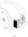
Figure 2 is an enlargement of an area of the vehicle containing the braking apparatus, -
Figure 3 is a cutaway view of a wheel assembly of the vehicle, on an enlarged scale and with parts removed for clarity. -
Figures 4 and5 show a horizontal section of a filter duct of the braking apparatus in corresponding distinct operating configurations, -
Figures 6 and 7 are perspective views, on an enlarged scale, of particulate filters of the braking apparatus, -
Figure 8 is a portion of a vertical section of a valve device applied to the filter duct, and -
Figure 9 is a plan view of a variant of the filter duct. - In
Figure 1 , reference number 1 is used to indicate a vehicle as a whole, specifically a motor vehicle, more specifically a racing motor vehicle. - According to a particular non-limiting example, the vehicle 1 is a Formula 1 single-seater, although the following is applicable to any motor vehicle.
- The vehicle 1 has a forward direction, which is in practice coincident with a roll axis X of the vehicle 1, and a frame F.
- Specifically, the vehicle 1 has four
wheels 2, each of which can rotate around its own axis or wheel axis A, generally transversely to the forward direction. - The vehicle 1 also includes, for each of the
wheels 2, a hub carrier, which is suitable for carrying therespective wheel 2 in a rotatable manner around its axis A. - The frame F is suspended in relation to the
wheels 2, which are intended to grip the ground, by well-known suspensions S not described in detail. - It should be noted that the
wheels 2 and the respective hub carriers are part of a non-suspended mass of the vehicle 1. - The vehicle 1 further comprises a
braking apparatus 4 to brake the vehicle 1. Thebraking apparatus 4 is associated with or coupled to one of thewheels 2, specifically a front wheel, although each of thewheels 2 can preferably be associated with or coupled to a braking apparatus identical to thebraking apparatus 4. - The
braking apparatus 4 and theassociated wheel 2 are therefore part of a wheel assembly of the vehicle 1. - The
braking apparatus 4 comprises abraking apparatus 5, in particular a disc type braking apparatus, having at least one pair offriction members disc 6 and at least onepad 7. More precisely, eachbraking apparatus 5 comprises twopads 7. - The following description will always refer to the
disc 6 and therelated pads 7, even though these components can always be replaced with generic friction members, such as, for example, a drum and a shoe, without any loss of generality. - The
disc 6 is fixed to thewheel 2, that is, it rotates integrally with it around the axis A. - On the other hand, the
pads 7 are free in relation to the rotation of thewheel 2, therefore they do not rotate integrally with thewheel 2, but rather they are carried by the hub carrier; the hub carrier, in turn, can be coupled to the frame F via the suspensions S. - As is known, for disc braking apparatuses such as the
specific apparatus 5, thepads 7 can be carried by a brake caliper, which in turn can be carried by the hub carrier. - The brake caliper is a component known per se and not shown, therefore its operation and layout in relation to the vehicle 1 will not be described in further detail.
- The
braking apparatus 5 can be selectively actuated to brake the vehicle 1 by pressing thedisc 6 andpads 7 against each other. In other words, the brake caliper is actuated to press thepads 7 against thedisc 6. - In this way, a pressure is generated between the
disc 6 and thepads 7. The pressure is the cause of a frictional force acting on both thedisc 6 andpads 7, but especially on thedisc 6 in order to brake the rotation of thewheel 2, and hence the vehicle 1. - Therefore, the braking corresponds to the pressure generated between the
disc 6 and thepads 7, i.e., the related frictional force developed, which increases with the pressure; in particular, the frictional force is proportional to the pressure. - The
braking apparatus 4 further comprises acooling duct 8 to cool thebraking apparatus 5, and in particular thedisc 6 andpads 7, for example during and/or after braking. - The
cooling duct 8 is defined by a plurality ofwalls walls 10 are part of the unsuspended masses, and of which in particular thewalls 11 are fixed to thewheel 2, so they rotate integrally with thewheel 2. Thewheel 2 is free to rotate with respect to thewalls 10 about its axis A. - The
cooling duct 8 extends between anair inlet 12 for the intake of outside air and an outlet opening 13 for the discharge of the air that entered through theair inlet 12. - At least the
disc 6 and also preferably thepads 7 are arranged in thecooling duct 8 so as to be hit by the flow of air flowing through thecooling duct 8 from theair inlet 12 to the outlet opening 13. - In greater detail, the
disc 6 and also preferably thepads 7 are located in the portion of thecooling duct 8 defined by thewalls 11. - For example, the
walls 11 can be considered as part of thewheel 2. More in particular, thewalls 11 include a rim of thewheel 2. - In particular, the
walls 10 comprise anannular wall 14 extending in a ring shape around the axis A and therefore arranged transversely or more precisely orthogonally to the axis A. In other words, theannular wall 14 is also part of the unsuspended mass of the vehicle 1 and is fixed to the hub carrier. - Due to its shape, the
annular wall 14 is normally referred to in automotive jargon as the "donut". - In the direction of the axis A, from the outside towards the inside of the vehicle 1, the
annular wall 14 covers thedisc 6 and preferably also thepads 7, so that the latter components are in particular invisible from the outside of the vehicle 1. - The
annular wall 14 is configured to prevent the air passing through the coolingduct 8 from flowing out of thewheel 2 along the axis A laterally towards the outside of the vehicle 1. - The
annular wall 14 defines at least partially anannular channel 15 inside thewheel 2 and forming part of the coolingduct 8. Thechannel 15 extends in a ring shape around the axis A. - In particular, the
disc 6 and preferably also thepads 7 are arranged in theannular channel 15. - In the specific example shown, although this is not essential in general, the
air inlet 12 is frontal, i.e., it is directed according to the forward direction of the vehicle 1 towards the front of the vehicle 1. - Furthermore, independently, in the specific example shown, although this is not essential in general, the outlet opening 13 faces a rear of the vehicle 1 according to the forward direction.
- In practice, the air flow entering the cooling
duct 8 through theair inlet 12 is directed along a direction parallel to and opposite to the forward direction. - The same applies, albeit independently, to the air flow leaving the cooling
duct 8 through theoutlet opening 13. - Again with reference to the specific example shown, although this is not essential in general, the cooling
duct 8 communicates with its exterior substantially only through theair inlet 12 and theoutlet opening 13. - The term substantially refers herein to the fact that in general the cooling
duct 8 extends along a path well defined by a continuous curve having two ends at theair inlet 12 and theoutlet opening 13, respectively; in use, the air flow substantially follows the path, without necessarily excluding negligible escapes from gaps between thewalls - This means that substantially all the air entering via the
air inlet 12 leaves the coolingduct 8 via theoutlet opening 13, unless there are refluxes through the same air inlet 12 (which would in any case be impossible, in particular, exceeding a speed threshold of the vehicle 1), or unless there are any negligible escapes. - In any case, the cooling
duct 8 is an element known per se in the field, therefore a very detailed description thereof is not considered necessary. - Preferably, the
outlet opening 13 and/or theair inlet 12 are defined by thewalls 10. - The
apparatus 4 further comprises afilter duct 20, preferably arranged on the outside of thewheel 2, for example behind thewheel 2 according to the forward direction of the vehicle 1. - The
filter duct 20 is fixed in relation to the coolingduct 8, with which it communicates. - The
filter duct 20 extends between an inlet communicating with theoutlet opening 13 and anoutlet 21 towards the external environment, i.e., communicating with the external environment, in particular directly. - In greater detail, the inlet of the
filter duct 20 matches, i.e. coincides with theoutlet opening 13. Therefore, all the air leaving the coolingduct 8 is transferred or passes to thefilter duct 20. - In other words, the
filter duct 20 is joined to the coolingduct 8 substantially in a fluid-tight manner through theoutlet opening 13. - The
filter duct 20 has twobranches first node 24 and preferably asecond node 25 distinct from thefirst node 24. In particular, thenodes filter duct 20, i.e., theoutlet opening 13. - According to an example, not shown, the
second node 25 could be missing, so that thefilter duct 20 would have an additional outlet for thebranch 23 in addition to theoutlet 21 that would remain for thebranch 22. - In practice, the
filter duct 20 splits at thenode 24 and preferably rejoins at thenode 25. - The
node 25 is thus arranged downstream of thenode 24, according to the direction that the air flow would have along thefilter duct 20 during the use of the vehicle 1. Theoutlet 21 would therefore be located downstream of thenode 25. - In general, in the remainder of the description, terms such as "upstream" and "downstream" will refer to the direction of the air flow along the
filter duct 20 during the use of the vehicle 1. - Clearly, the
filter duct 20 is bounded by anouter casing 26; similarly, thebranches outer casing 26. In particular, theouter casing 26 is in turn carried by thewalls 10 in a fixed position in relation to thewalls 10. - The
apparatus 4 also includes avalve device 27, in particular carried by theouter casing 26. - The
valve device 27 comprises anobstructer element 28, for example a wall or bulkhead or a set of walls or bulkheads, adapted to plug or obstruct or close, at least partially or totally, thebranches - Obstructing, plugging, or closing partially the
branch 22 or thebranch 23 means bringing theobstructer element 28 to a position or point on thebranch 22 or thebranch 23, thereby reducing the air flow rate through the same position on thebranch 22 or thebranch 23 compared to the flow rate that would occur if theobstructer element 28 had not occupied the position on thebranch 22 or thebranch 23. Obstructing, plugging, or closing totally thebranch 22 or thebranch 23 means bringing theobstructer element 28 to a position or point on thebranch 22 or thebranch 23, thereby preventing an air flow rate through the same position on thebranch 22 or thebranch 23. - The
valve device 27 can be controlled or is configured to be controlled according to at least one first configuration or filtering configuration (Figure 5 ), in which theobstructer element 28 obstructs at least partially or totally thebranch 22 and clears or opens, in particular totally, thebranch 23. - Clearing or opening the
branch 22 or thebranch 23 means moving theobstructer element 28 so as to increase the air flow rate through thebranch 22 or thebranch 23. Clearing or opening totally thebranch 22 or thebranch 23 means that theobstructer element 28 does not occupy or is spaced from thebranch 22 or thebranch 23. - Furthermore, the
valve device 27 can be controlled or is configured to be controlled according to at least one second configuration or basic configuration (Figure 4 ), in which theobstructer element 28 obstructs at least partially or totally thebranch 23 and clears or opens, in particular totally, thebranch 22. - Specifically, the
valve device 27 operates at thenode 24, so theobstructer element 28 is arranged at thenode 24 in a movable manner between at least two positions corresponding to the filtering configuration and the basic configuration, respectively. - More specifically, the
obstructer element 28 is pivoted around an axis K at thenode 24, so it can rotate between two positions corresponding to the filtering configuration and the basic configuration, respectively (Figures 5 and4 ) . In the non-limiting embodiment shown, the axis K is vertical, i.e. directed in the direction of the force of gravity; however, the axis K could be clearly oriented differently. - The
valve device 27 operates normally in the basic configuration. In other words, thevalve device 27 specifically includes a return member, particularly an elastic return member, such as for example aspring 29, configured to exert a return force or reaction on theobstructer element 28 when theobstructer element 28 is moved away from the position corresponding to the basic configuration, where the return force or reaction is directed to return theobstructer element 28 to the position corresponding to the basic configuration. - The
spring 29 has ends coupled to theouter casing 26 and theobstructer element 28, respectively. Specifically, thespring 29 is arranged around the axis K. In particular, thespring 29 is a torsional spring, so it is configured to exert the return reaction as a torque around the axis K. - The
apparatus 4 further comprises afilter 30 arranged at thebranch 23 and configured to filter particulate from the air passing through thebranch 23. For example, thefilter 30 is fixed in relation to thebranch 23; in particular, thefilter 30 is fixed to theouter casing 26 within thebranch 23. - Specifically, the particulate is that produced by the pressure between the
disc 6 and thepads 7 when braking the vehicle 1. The particulate may include carbonaceous particles, with the possible addition of silicon, iron, titanium, magnesium, barium, bromine, potassium, and sodium particles. - The
filter 30 is more precisely configured to capture the particulate, while allowing air to pass or transpire. - In greater detail, the
filter 30 comprises a filter weave capable of retaining the particulate, while allowing the air to pass through. - For example, the weave of the
filter 30 may form at least one grid, for example extending over a rectangular section plane, in particular with elements oriented along the height (or the long side) or along the width (or the short side), or both, or with, alternatively or even additionally, elements oriented obliquely. - Conveniently, the grid extends over a plane inclined from a vertical plane; in this way, the captured particulate can fall more easily from the
filter 30 with the contribution of gravity. - For example, the weave of the
filter 30 can be a pleated weave. - Preferably, the
filter 30 is configured to filter particulate with dimensions at least greater than 70 microns, more preferably at least greater than 35 microns, even more preferably at least greater than 3-4 microns. - Advantageously, the
apparatus 4 also includes areservoir 31 to collect the particulate filtered by thefilter 30. - The
reservoir 31 has anaccess port 32 at thebranch 23 between thenode 24 or thevalve device 27 and thefilter 30. Theaccess port 32 receives the particulate into thereservoir 31; in other words, the particulate is deposited into thereservoir 31 through theaccess port 32. - In greater detail, the
access port 32 is located in a position such as to receive particulate falling from thefilter 30 by gravity or in the direction of gravity. - Specifically, the
access port 32 is immediately upstream of thefilter 30. - In addition, the
access port 32 is preferably arranged under thefilter 30, in particular immediately below it. - In other words, on the side upstream of the
filter 30, thefilter 30 itself faces theaccess port 32.
Preferably, theobstructer element 28 comprises a through-slot 33. Therefore, because of theslot 33, thebranches node 24, at least through theslot 33. In particular, it is possible to define a direction H passing through theslot 33 when thevalve device 27 is in the basic configuration (Figure 4 ). - Preferably, the
filter duct 20 comprises aportion 20a with a convergent or convergent-divergent section, proceeding, in particular transversely to the direction H, in the direction oriented from the outlet opening 13 to theoutlet 21. Theportion 20a is arranged along thebranch 22 and at theslot 33 when thevalve device 27 is arranged in the basic configuration (Figure 4 ). Specifically, theportion 20a is defined by thebranch 22 and theobstructer 28 when thevalve device 27 is arranged in the basic configuration. - In detail, proceeding along the
branch 22 in the direction oriented from the outlet opening 13 towards theoutlet 21 at theportion 20a, thecasing 26 comprises asection 26a facing the lumen of thebranch 22 and/or defining the lumen of thebranch 22 and extending over progressively decreasing distances from the partition wall D along the direction H. - In the embodiment shown, the
portion 20a is convergent-divergent and therefore thecasing 26 further includes asection 26b, also facing the lumen of thebranch 22 and/or defining the lumen of thebranch 22 and extending over progressively increasing distances from the partition wall D along the direction H. - The
casing 26 further comprises asection 26c facing the lumen of thebranch 22, interposed between thesections section 26c is at least partly aligned with theslot 33 perpendicularly to the direction H when thevalve device 27 is arranged in the basic configuration. - Similarly, when the
valve device 27 is arranged in the basic configuration, proceeding along thebranch 22 in the direction oriented from the outlet opening 13 towards theoutlet 21, theobstructer 28 comprises: - a
section 28a facing the lumen of thebranch 22 and extending over progressively increasing distances from the partition wall D along the direction H; and - a
section 28b, also facing the lumen of thebranch 22 and extending over progressively decreasing distances from the partition wall D along the direction H. - The
obstructer 28 further comprises asection 28c facing the lumen of thebranch 22, interposed between thesections slot 33 is arranged at thesection 28c. - In addition, considering a direction orthogonal to the direction H, the
section 26a is at least partly aligned with thesection 28a, and thesection 26b is at least partly aligned with thesection 28b. - In other words, the
sections portion 20a; thesections 26b contribute to forming the divergent region of theportion 20a; lastly, thesections portion 20a, at which theslot 33 is arranged. - The
portion 20a is adapted to cause a depression of the flow of air flowing through thebranch 22 at theslot 33. - The
branches node 25, in particular always. - Therefore, with the
valve device 27 in the basic configuration, communication between thebranches node 25 may lead to a backflow of air from thenode 25 towards thenode 24, in particular thanks to theportion 20a. In greater detail, the air backflow is caused by the depression established at theportion 20a where theslot 33 is . - The backflow is beneficial to the
filter 30, as it favours the cleaning thereof, i.e., the fall of the captured particulate, in particular towards theaccess port 32 or thereservoir 31. - Conveniently, in order to prevent the particulate from recirculating from the
branch 23 to thebranch 22 through theslot 33 due to the backflow, theapparatus 4 comprises afilter 35 at theslot 33. - The
filter 35 is configured to filter the particulate from the air, similar to thefilter 30, although thefilter 35 may be simpler and smaller than thefilter 30. In addition, thefilter 35 could have less filtering power than thefilter 30. - The
filter 35 is configured to filter the air passing through theslot 33. - The
filter 35 is preferably attached to theobstructer element 28. - Furthermore, when the
valve device 27 is in the basic configuration, thefilter 35 is arranged on the side of thebranch 23. More generally, thefilter 35 is arranged downstream of thenode 24. - In the embodiment shown, the
apparatus 4 preferably, but not necessarily, comprises anadditional filter 38 configured to filter the air passing through theoutlet 21. Thefilter 38 is arranged at theoutlet 21. - The
filter 38 could be constructively similar to thefilter 35, i.e., it could have the same characteristics as described above for thefilter 35. - The
apparatus 4 further comprises anactuating assembly 40 configured to lead thevalve device 27 into the filtering configuration from the basic configuration in response to the braking of the vehicle 1, i.e., in response to the pressure between thedisc 6 and thepads 7. - In particular, the actuating
assembly 40 could include anactuator 41, e.g. an electric actuator, that can be controlled to move or actuate thevalve device 27 or more precisely theobstructer element 28 from the basic configuration to the filtering configuration. - In fact, the
actuator 41 rotates theobstructer element 28 around the axis K, in particular against the action of thespring 29, towards the filtering configuration of thevalve device 27. - In the drawings, the
actuator 41 is arranged in a position aligned along the axis K with theobstructer element 28 and is preferably coupled directly to theobstructer element 28 to make it rotate. However, theactuator 41 could also be remote from theobstructer element 28 or more generally from thevalve device 27; in fact, the power that actuates thevalve device 27 can be transmitted by theactuator 41 via any transmission, possibly even a well-known type of transmission (for example including one or more of gear wheels, clutches, couplings, belts, cables, chains, and similar well-known transmission elements). - The
actuator 41 could even be a hydraulic or pneumatic actuator, instead of an electric actuator, without any loss of generality. - Preferably, the
apparatus 4 further comprises atransducer 42 configured to detect a quantity indicative of the occurrence of braking and to generate a related signal. - For example, the
transducer 42 detects a quantity indicative of the pressure between thedisc 6 and thepads 7. - In this case, the signal generated by the
transducer 42 is indicative of the occurrence of braking when the quantity detected by thetransducer 42, e.g., the pressure, exceeds a defined threshold, e.g., greater than 3 bar. In practice, the signal carries information about whether or not the pressure exceeds the pressure threshold. - The
apparatus 4 also includes acontrol unit 43 configured to receive the signal generated by thetransducer 42 and to control theactuator 41 to move or actuate thevalve device 27 into the filtering configuration when the signal indicates that braking has occurred, that is, when the pressure exceeds the pressure threshold. - The pressure threshold is, for example, stored in the
control unit 43. - Actuating the
valve device 27 into the filtering configuration means, specifically, as already explained above, leading theobstructer element 28 from the position corresponding to the basic configuration to the position corresponding to the filtering configuration. - Preferably, the
apparatus 4 further comprises a measuring or estimating device (not shown) to determine (e.g. by direct detection or by estimation from other quantities detected or determined by the control unit 43) a quantity representative of a forward movement of the vehicle 1, e.g. a quantity indicative of the speed or acceleration of the vehicle 1. - The
control unit 43 is coupled to the measuring or estimating device, so as to obtain information on the determined quantity. - In particular, the
control unit 43 has an additional condition, the occurrence of which is preferably necessary to control theactuator 41 to actuate thevalve device 27 in the filtering configuration, in addition to the occurrence of the above described pressure threshold condition. - The additional condition is that the quantity determined by the measuring or estimating device indicates that the forward movement of the vehicle is beyond a minimum movement threshold at the time of the occurrence of braking, i.e., at the time when the pressure exceeds the pressure threshold.
- For example, the additional condition occurs when the speed or acceleration of the vehicle 1 is above a corresponding minimum threshold.
- The
control unit 43 determines whether or not the additional condition has occurred as it is coupled to the measuring or estimating device, i.e., as it has the information on the quantity determined by the measuring or estimating device. - In this way, the
control unit 43 brings thevalve device 27 into the filtering configuration only if the vehicle 1 is actually moving at the time of braking. In fact, in the event that the vehicle 1 is stationary, braking would not produce a particulate to justify the filtering configuration. - According to the variant in
Figure 9 , theactuator 41 is replaced in its function by amass 45 oscillating by means of anelastic device 46, in particular a spring. - The
mass 45 is part of theapparatus 4 and is coupled to asupport 47, e.g., fixed in relation to thecasing 26, or to another component of the vehicle 1, e.g., thefilter duct 20, by means of theelastic device 46. - The
support 47 is part of theapparatus 4 and is configured to guide themass 45 along a direction W oriented to have at least one component along the forward direction of the vehicle 1, or more preferably parallel to the same forward direction. - Again with reference to the variant in
Figure 9 , themass 45 is coupled to thevalve device 27 or more precisely to theobstructer element 28 by means of amechanism 48, e.g., an articulated mechanism, configured to move or actuate thevalve device 27 into the filtering configuration from the basic configuration in response to a translation of the mass 45 caused by braking along the direction W with respect to the support 47 (i.e., to rotate theobstructer element 28 from the position corresponding to the basic configuration to the position corresponding to the filtering configuration). - In fact, the
mass 45 moves during the braking of the vehicle 1 in relation to thesupport 47 due to inertial effects (in fact, themass 45 is suspended in relation to thesupport 47 by means of the elastic device 46), i.e., due to the inertia force that develops on themass 45 caused by the braking. - The movement of the mass 45 results in the actuation of the
valve device 27 by means of themechanism 48, for example also part of theapparatus 4. - Clearly, the
mechanism 48 could be made in many ways to perform its function described herein; therefore, the construction of themechanism 48 will not be described in detail here. For example, the operation of thespecific mechanism 48 shown inFigure 8 is evident from the sameFigure 9 . - When the braking of the motor vehicle 1 stops, the
elastic device 46 returns the mass 45 to its initial position. In this way, thevalve device 27 also returns to the basic configuration, for example by means of thespring 29, which actually is no longer required in this variant since its function can evidently be replaced by theelastic device 46 via themechanism 48. - Advantageously, especially for the variant in
Figure 9 or even in general, theapparatus 4 comprises a sensor 50 (Figure 8 ) configured to determine the position of theobstructer element 28. For example, thesensor 50 can communicate the position of theobstructer element 28 to thecontrol unit 43. - In particular, the
sensor 50 can be a magnetic sensor, more particularly a Hall effect sensor. - During the operation of the vehicle 1, the braking of the vehicle 1, i.e., the pressure between the
disc 6 and thepads 7, activates the actuatingassembly 40 which leads thevalve device 27 into the filtering configuration. - In the meantime, the vehicle 1 is still moving forward, so an aerodynamic air flow develops in the direction opposite to the forward direction of the vehicle 1. Therefore, at least a portion of the air flow enters the cooling
duct 8 via theair inlet 12. - The same portion of the air flow reaches the
filter duct 20 via theoutlet opening 13, after having hit and cooled thebraking apparatus 5, and in particular thedisc 6 and thepads 7. - In the filtering configuration, the
obstructer element 28 at least partially obstructs thebranch 22, thus inducing the portion of the air flow coming from the coolingduct 8 to travel along thebranch 23. - Therefore, the air flow that travels along the
branch 23 is here loaded with particulate produced by the friction between thedisc 6 and thepads 7. - In the
branch 23, the air flow meets thefilter 30, which retains the particulate and allows the air to flow towards theoutlet 21 via thenode 25. - When the braking stops, the actuating
assembly 40 is configured to return thevalve device 27 into the basic configuration. This is done, in particular, by the return member, specifically defined by thespring 29. - Here, the air flow coming from the cooling
duct 8 does not contain particulate or at least contains a very small amount thereof compared to the case of braking of the vehicle 1. - Here, the
obstructer element 28 at least partially obstructs thebranch 23, thus inducing the portion of the air flow coming from the coolingduct 8 to pass through thebranch 22. Therefore, the portion of the air flow substantially bypasses thebranch 23 and reaches theoutlet 21. - In this phase, the normal vibrations from the operation of the vehicle 1 help the particulate retained by the
filter 30 to detach from thefilter 30, so that preferably it falls into thereservoir 31. - Due to the presence of the
slot 33, the air flow in any case prefers to pass through thebranch 22, but a backflow can develop along thebranch 23 from thenode 25, where in any case thebranches node 24. The backflow favours even further the detachment of the particulate from thefilter 30, as well as its falling into thereservoir 31. - The advantages of the
apparatus 4 and the vehicle 1 according to the invention are clear from the foregoing. - The
filter duct 20 prevents the spreading of particulate from thebraking apparatus 5 into the environment. - In particular, the particulate is retained in the
filter duct 20 while the vehicle 1 is moving without braking. In fact, without the braking of the vehicle 1, the airflows through the coolingduct 8 bypass thebranch 23, where thefilter 30 retains the particulate collected during the braking of the vehicle 1. - Here, the particulate falls into the
reservoir 31, thus becoming trapped. - Lastly, it is clear that modifications and variations may be made to the
apparatus 4 and the vehicle 1 according to the invention, without however departing from the scope of protection defined by the claims. - In particular, the number and shape of the components described and illustrated herein may be different.
- Moreover, the various examples described herein can be combined with one another to determine further embodiments within the aforementioned scope of protection.
- In particular, the
braking apparatuses 5 could be in positions other than those illustrated in relation to thewheels 2. For example, thebraking apparatuses 5 could be arranged in the centre of the vehicle 1.
Claims (14)
- A braking apparatus (4) for a vehicle (1), the apparatus comprising- a braking apparatus (5) having at least one pair of friction members (6, 7) and selectively operable to provoke braking of the vehicle (1) by pressing the friction members (6, 7) against each other, so that the pressure between the friction members (6, 7) causes a frictional force acting on the members (6, 7) and increasing with the pressure,- a cooling duct (8) extending between an air inlet (12) for the intake of outside air and an outlet opening (13) for discharging the air that entered through the air inlet (12), wherein at least one of the friction members (6, 7) is arranged in the cooling duct (8) so that it can be hit by a flow of air flowing through the cooling duct (8),- a filter duct (20) extending between an inlet communicating with the outlet opening (13) and an outlet (21) to the external environment, the filter duct (20) having a first and a second branch (22, 23) arranged in parallel,- valve means (27) comprising an obstructer element (28) and controllable according to at least a first configuration, in which the obstructer element (28) at least partially obstructs the first branch (22) and clears the second branch (23), and a second configuration, in which the obstructer element (28) at least partially obstructs the second branch (23) and clears the first branch (22),- a first filter (30) arranged at the second branch (23) and configured to filter particulate from the air passing through the second branch (23), and- actuating means (40) configured to drive the valve means (27) into the first configuration from the second configuration in response to the braking of the vehicle (1) .
- The braking apparatus according to claim 1, wherein the outlet opening (13) matches the inlet of the filter duct (20), so that all the air leaving the cooling duct (8) passes to the filter duct (20).
- The braking apparatus according to claim 1 or 2, wherein the cooling duct (8) communicates with the outside only via the air intake (12) and the outlet opening (13).
- The braking apparatus according to any one of the preceding claims, further comprising a reservoir (31) for collecting the particulate filtered by the first filter (30), the reservoir having an access port (32) for receiving the particulate at the second branch (23) between the valve means (27) and the first filter (30).
- The braking apparatus according to claim 4, wherein the access port (32) of the reservoir (31) is located in a position to receive particulate falling from the first filter (30) by gravity, in particular immediately upstream of the first filter (30).
- The braking apparatus according to any one of the preceding claims, wherein the obstructer element (28) comprises a slot (33) such that the first and second branches (22, 23) communicate via the slot (33) along a pass-through direction (H) through the slot (33) when the valve means (27) are in the second configuration.
- The braking apparatus according to claim 6, wherein the filter duct (20) comprises a portion (20a) with a convergent or convergent-divergent type section proceeding transversely to said direction (H) in the oriented direction from said outlet opening (13) to said outlet (21); said portion (20a) being arranged along the first branch (22) and at the slot (33), when the valve means (27) are in the second configuration.
- The braking apparatus according to claim 6 or 7, comprising a second filter (35) for filtering particulate from the air, the second filter (35) being attached to the obstructer element (28) at the slot (33).
- The braking apparatus according to any of the preceding claims, wherein the actuating means (40) comprise- an actuator (41) controllable to move the valve means (27) from the second configuration to the first configuration,- a transducer (42) configured to detect a quantity indicative of the occurrence of braking and to generate a related signal, and- a control unit (43) configured to receive the signal and to control the actuator (41) to move the valve means (27) to the first configuration when the signal indicates the occurrence of braking.
- The braking apparatus according to claim 9, wherein the quantity is indicative of said pressure, and wherein the signal indicates the occurrence of braking when the pressure is greater than a pressure threshold.
- The braking apparatus according to claim 9 or 10, further comprising a measuring or estimating device configured to determine a quantity representative of a forward movement of the vehicle (1), wherein the control unit (43) is coupled to the measuring or estimating device and is configured to control the actuator (41) to move the valve means (27) into the first configuration with the additional condition that the quantity determined by the measuring or estimating device indicates that the forward movement of the vehicle (1) is beyond a minimum movement threshold at the time of the occurrence of braking.
- A wheel assembly for a vehicle, the wheel assembly comprising a wheel (2) and a braking apparatus (4) according to any one of the preceding claims, wherein one of the friction members (6, 7) is fixed to the wheel (2).
- A vehicle comprising a wheel assembly according to claim 12.
- The vehicle according to claim 13, having a forward direction, wherein the outlet opening (13) faces a rear of the vehicle (1) according to the forward direction, so that a flow of air flowing out through the outlet opening (13) is directed along a direction parallel to and opposite to the forward direction.
Applications Claiming Priority (1)
| Application Number | Priority Date | Filing Date | Title |
|---|---|---|---|
| IT102023000017799A IT202300017799A1 (en) | 2023-08-30 | 2023-08-30 | BRAKING SYSTEM FOR A VEHICLE WITH A FILTERING UNIT FOR FILTERING PARTICULATE MATTER PRODUCED BY THE OPERATION OF THE BRAKING SYSTEM |
Publications (1)
| Publication Number | Publication Date |
|---|---|
| EP4516608A1 true EP4516608A1 (en) | 2025-03-05 |
Family
ID=88689848
Family Applications (1)
| Application Number | Title | Priority Date | Filing Date |
|---|---|---|---|
| EP24196903.9A Pending EP4516608A1 (en) | 2023-08-30 | 2024-08-28 | Braking apparatus for a vehicle with a filtering assembly for filtering particulate produced by the operation of the braking apparatus |
Country Status (5)
| Country | Link |
|---|---|
| US (1) | US20250075755A1 (en) |
| EP (1) | EP4516608A1 (en) |
| JP (1) | JP2025036335A (en) |
| CN (1) | CN119527247A (en) |
| IT (1) | IT202300017799A1 (en) |
Families Citing this family (1)
| Publication number | Priority date | Publication date | Assignee | Title |
|---|---|---|---|---|
| EP4249764B1 (en) * | 2020-11-23 | 2026-05-13 | Wuhan Lotus Cars Co., Ltd. | Brake dust filtering apparatus and vehicle |
Citations (3)
| Publication number | Priority date | Publication date | Assignee | Title |
|---|---|---|---|---|
| US8678426B1 (en) * | 2013-02-01 | 2014-03-25 | GM Global Technology Operations LLC | Vehicle brake cooling system |
| US20170248180A1 (en) * | 2016-02-25 | 2017-08-31 | Continental Automotive France | Method and device for capturing particles ejected by the friction braking elements of a disk brake system |
| FR3116001A1 (en) * | 2020-11-12 | 2022-05-13 | Tallano Technologie | Filtration system with collecting tank |
-
2023
- 2023-08-30 IT IT102023000017799A patent/IT202300017799A1/en unknown
-
2024
- 2024-08-09 US US18/798,912 patent/US20250075755A1/en active Pending
- 2024-08-28 EP EP24196903.9A patent/EP4516608A1/en active Pending
- 2024-08-29 JP JP2024147428A patent/JP2025036335A/en active Pending
- 2024-08-29 CN CN202411201772.1A patent/CN119527247A/en active Pending
Patent Citations (3)
| Publication number | Priority date | Publication date | Assignee | Title |
|---|---|---|---|---|
| US8678426B1 (en) * | 2013-02-01 | 2014-03-25 | GM Global Technology Operations LLC | Vehicle brake cooling system |
| US20170248180A1 (en) * | 2016-02-25 | 2017-08-31 | Continental Automotive France | Method and device for capturing particles ejected by the friction braking elements of a disk brake system |
| FR3116001A1 (en) * | 2020-11-12 | 2022-05-13 | Tallano Technologie | Filtration system with collecting tank |
Also Published As
| Publication number | Publication date |
|---|---|
| IT202300017799A1 (en) | 2025-03-02 |
| CN119527247A (en) | 2025-02-28 |
| JP2025036335A (en) | 2025-03-14 |
| US20250075755A1 (en) | 2025-03-06 |
Similar Documents
| Publication | Publication Date | Title |
|---|---|---|
| US20250075755A1 (en) | Braking apparatus for a vehicle with a filtering assembly for filtering particulate produced by the operation of the braking apparatus | |
| JP6953522B2 (en) | Brake pads and brake units for capturing dust | |
| WO2017073574A1 (en) | Disc-brake device | |
| KR102671742B1 (en) | Brake pad for disc brake assemblies including a chamfered front area and a suction groove within the front area | |
| JP7424655B2 (en) | Brake pads with particulate and dust collection | |
| US10072716B2 (en) | Method and device for capturing particles ejected by the friction braking elements of a disk brake system | |
| US20100065387A1 (en) | Brake dust collecting device | |
| CN113374811B (en) | Disc brake device for vehicle and vehicle with such disc brake device | |
| KR102843828B1 (en) | A braking system in which air is injected into grooves within the lining | |
| US20140054120A1 (en) | Brake Dust Collector for Motor Vehicles | |
| DE102019133772B4 (en) | Vehicle fine dust collector and vehicle | |
| JP6475678B2 (en) | Brake dust cover | |
| KR102649681B1 (en) | Disc brake pads having obliquely extending collection grooves | |
| GB2583457A (en) | A brake disc cover | |
| KR102815391B1 (en) | Braking system with centrifugal suction in the grooves of the lining | |
| KR102788459B1 (en) | Electrostatic precipitator of brake pad wear particles | |
| JP2018533706A5 (en) | ||
| CN108291594A (en) | Disc brake caliper body | |
| US11828340B2 (en) | Device and friction brake for reducing the amount of fine dust | |
| JP2017082969A (en) | Pad for disc brake and disc brake device | |
| JPS6040905Y2 (en) | Disc brake drag prevention device | |
| WO2017065500A1 (en) | Brake cooling device for vehicle | |
| KR102479622B1 (en) | Sequential braking device | |
| JP2025129736A (en) | Brake dust collector | |
| EP4520994A1 (en) | Brake dust filter system |
Legal Events
| Date | Code | Title | Description |
|---|---|---|---|
| PUAI | Public reference made under article 153(3) epc to a published international application that has entered the european phase |
Free format text: ORIGINAL CODE: 0009012 |
|
| STAA | Information on the status of an ep patent application or granted ep patent |
Free format text: STATUS: THE APPLICATION HAS BEEN PUBLISHED |
|
| AK | Designated contracting states |
Kind code of ref document: A1 Designated state(s): AL AT BE BG CH CY CZ DE DK EE ES FI FR GB GR HR HU IE IS IT LI LT LU LV MC ME MK MT NL NO PL PT RO RS SE SI SK SM TR |
|
| STAA | Information on the status of an ep patent application or granted ep patent |
Free format text: STATUS: REQUEST FOR EXAMINATION WAS MADE |
|
| GRAP | Despatch of communication of intention to grant a patent |
Free format text: ORIGINAL CODE: EPIDOSNIGR1 |
|
| STAA | Information on the status of an ep patent application or granted ep patent |
Free format text: STATUS: GRANT OF PATENT IS INTENDED |
|
| 17P | Request for examination filed |
Effective date: 20250825 |
|
| INTG | Intention to grant announced |
Effective date: 20250926 |
|
| GRAJ | Information related to disapproval of communication of intention to grant by the applicant or resumption of examination proceedings by the epo deleted |
Free format text: ORIGINAL CODE: EPIDOSDIGR1 |
|
| STAA | Information on the status of an ep patent application or granted ep patent |
Free format text: STATUS: REQUEST FOR EXAMINATION WAS MADE |
|
| INTC | Intention to grant announced (deleted) | ||
| GRAP | Despatch of communication of intention to grant a patent |
Free format text: ORIGINAL CODE: EPIDOSNIGR1 |
|
| STAA | Information on the status of an ep patent application or granted ep patent |
Free format text: STATUS: GRANT OF PATENT IS INTENDED |
|
| INTG | Intention to grant announced |
Effective date: 20260120 |
|
| GRAS | Grant fee paid |
Free format text: ORIGINAL CODE: EPIDOSNIGR3 |
|
| GRAA | (expected) grant |
Free format text: ORIGINAL CODE: 0009210 |
|
| STAA | Information on the status of an ep patent application or granted ep patent |
Free format text: STATUS: THE PATENT HAS BEEN GRANTED |