EP4516607A1 - A method for providing driver feedback - Google Patents
A method for providing driver feedback Download PDFInfo
- Publication number
- EP4516607A1 EP4516607A1 EP23194119.6A EP23194119A EP4516607A1 EP 4516607 A1 EP4516607 A1 EP 4516607A1 EP 23194119 A EP23194119 A EP 23194119A EP 4516607 A1 EP4516607 A1 EP 4516607A1
- Authority
- EP
- European Patent Office
- Prior art keywords
- brake signal
- signal curve
- braking operation
- braking
- parameter
- Prior art date
- Legal status (The legal status is an assumption and is not a legal conclusion. Google has not performed a legal analysis and makes no representation as to the accuracy of the status listed.)
- Withdrawn
Links
Images



Classifications
-
- B—PERFORMING OPERATIONS; TRANSPORTING
- B60—VEHICLES IN GENERAL
- B60T—VEHICLE BRAKE CONTROL SYSTEMS OR PARTS THEREOF; BRAKE CONTROL SYSTEMS OR PARTS THEREOF, IN GENERAL; ARRANGEMENT OF BRAKING ELEMENTS ON VEHICLES IN GENERAL; PORTABLE DEVICES FOR PREVENTING UNWANTED MOVEMENT OF VEHICLES; VEHICLE MODIFICATIONS TO FACILITATE COOLING OF BRAKES
- B60T17/00—Component parts, details, or accessories of power brake systems not covered by groups B60T8/00, B60T13/00 or B60T15/00, or presenting other characteristic features
- B60T17/18—Safety devices; Monitoring
- B60T17/22—Devices for monitoring or checking brake systems; Signal devices
-
- B—PERFORMING OPERATIONS; TRANSPORTING
- B60—VEHICLES IN GENERAL
- B60T—VEHICLE BRAKE CONTROL SYSTEMS OR PARTS THEREOF; BRAKE CONTROL SYSTEMS OR PARTS THEREOF, IN GENERAL; ARRANGEMENT OF BRAKING ELEMENTS ON VEHICLES IN GENERAL; PORTABLE DEVICES FOR PREVENTING UNWANTED MOVEMENT OF VEHICLES; VEHICLE MODIFICATIONS TO FACILITATE COOLING OF BRAKES
- B60T8/00—Arrangements for adjusting wheel-braking force to meet varying vehicular or ground-surface conditions, e.g. limiting or varying distribution of braking force
- B60T8/17—Using electrical or electronic regulation means to control braking
- B60T8/172—Determining control parameters used in the regulation, e.g. by calculations involving measured or detected parameters
-
- B—PERFORMING OPERATIONS; TRANSPORTING
- B60—VEHICLES IN GENERAL
- B60T—VEHICLE BRAKE CONTROL SYSTEMS OR PARTS THEREOF; BRAKE CONTROL SYSTEMS OR PARTS THEREOF, IN GENERAL; ARRANGEMENT OF BRAKING ELEMENTS ON VEHICLES IN GENERAL; PORTABLE DEVICES FOR PREVENTING UNWANTED MOVEMENT OF VEHICLES; VEHICLE MODIFICATIONS TO FACILITATE COOLING OF BRAKES
- B60T2220/00—Monitoring, detecting driver behaviour; Signalling thereof; Counteracting thereof
- B60T2220/02—Driver type; Driving style; Driver adaptive features
-
- B—PERFORMING OPERATIONS; TRANSPORTING
- B60—VEHICLES IN GENERAL
- B60T—VEHICLE BRAKE CONTROL SYSTEMS OR PARTS THEREOF; BRAKE CONTROL SYSTEMS OR PARTS THEREOF, IN GENERAL; ARRANGEMENT OF BRAKING ELEMENTS ON VEHICLES IN GENERAL; PORTABLE DEVICES FOR PREVENTING UNWANTED MOVEMENT OF VEHICLES; VEHICLE MODIFICATIONS TO FACILITATE COOLING OF BRAKES
- B60T2270/00—Further aspects of brake control systems not otherwise provided for
- B60T2270/40—Failsafe aspects of brake control systems
- B60T2270/406—Test-mode; Self-diagnosis
Definitions
- the invention relates to a method and an arrangement for providing driver feedback to a driver of a vehicle, particularly for a driver driving a vehicle on a racetrack.
- An objective of the invention is to provide a method for providing driver feedback to a driver of a vehicle, by which method the driver can learn and improve the way of braking the vehicle for optimizing the braking operation.
- the objective is achieved by a method for providing driver feedback to a driver of a vehicle, wherein the method comprises receiving a brake signal and recording the brake signal as a function of time, which brake signal correlates to or is a direct measure of a brake torque provided by a brake of the vehicle during a braking operation, creating a brake signal curve based on the received brake signal and evaluating the brake signal curve with respect to a braking parameter for determining the quality of the braking operation, and providing the driver feedback based on the determined quality of the braking operation to a driver information system of the vehicle.
- the invention is based on the insight that by such a method, a quantified value of the quality of the braking operation can be provided to the driver, preferably immediately after the braking operation has been performed.
- the smoothness of the braking operation can be evaluated and the braking operation can be given a score, and the braking operation score and/or coaching tips based on the braking operation score can be presented to the driver by the driver information system.
- the brake signal can be provided in various ways, as long as the measured and received brake signal correlates to or is a direct measure of the brake torque, such as from a sensor measuring the travel or depression of a brake pedal of the vehicle, from a sensor measuring a hydraulic brake pressure of a brake of the vehicle, from a control unit providing a signal for requested brake force or brake torque of a brake of the vehicle, or from a sensor measuring the current brake force or brake torque applied.
- the method comprises identifying a maximum brake signal peak that occurred during the braking operation and dividing the brake signal curve into a first portion of the brake signal curve before the maximum brake signal peak and a second portion of the brake signal curve after the maximum brake signal peak, and evaluating the first portion of the brake signal curve with respect to a first braking parameter and the second portion of the brake signal curve with respect to a second braking parameter.
- the first braking parameter is an area under the brake signal curve and/or the second parameter is an area under the brake signal curve.
- the first braking parameter is an area under the brake signal curve
- the method comprises comparing the area under the brake signal curve in the first portion of the brake signal curve with a reference area, and determining the quality of the braking operation by a ratio between the brake signal curve area and the reference area, wherein the ratio is ⁇ 1, and the bigger ratio, the higher quality of the braking operation.
- the second braking parameter is an area under the brake signal curve
- the method comprises comparing the area under the brake signal curve in the second portion of the brake signal curve with a reference area, and determining the quality of the braking operation by a ratio between the brake signal curve area and the reference area, wherein the ratio is ⁇ 1, and the smaller ratio, the higher quality of the braking operation.
- the first parameter is the derivative of the brake signal curve
- the presence of a negative derivative of the first portion of the brake signal curve is defined as lowering the quality of the braking operation.
- the first parameter is the shape of brake signal curve
- the presence of a local maxima or local minima of the first portion of the brake signal curve is defined as lowering the quality of the braking operation.
- a local maxima or minima would result in a longer application of the brake torque which in turn leads to an increased lap time when driving on a racetrack.
- the second parameter is the derivative of the brake signal curve
- the presence of a positive derivative of the second portion of the brake signal curve is defined as lowering the quality of the braking operation.
- the second parameter is the shape of brake signal curve
- the presence of a local maxima or local minima of the second portion of the brake signal curve is defined as lowering the quality of the braking operation.
- a local maxima or minima would result in a longer application of the brake torque which in turn leads to an increased lap time when driving on a racetrack.
- the method comprises identifying a start of the braking operation when the measured brake signal increases to a start value exceeding a first threshold value and an end of the braking operation when the measured brake signal decreases to an end value which is smaller than a second threshold value.
- the first threshold value and the second threshold value can be the same.
- the method comprises defining the braking operation as a single braking operation provided that the time period between the end value of the braking operation and a start value of a second subsequent braking operation is longer than a predetermined time period.
- the method comprises showing the driver feedback comprising a quantified performance value and/or coaching tip for the braking operation on a display of the driver information system.
- the driver can receive driver feedback in a suitable way while driving the vehicle.
- quantified performance values and coaching tips such as a description of how the braking operation can be improved to reduce the lap time when driving on a racetrack, the driver can adjust the braking behaviour and immediately see the result thereof.
- the invention relates to an arrangement for providing driver feedback to a driver of a vehicle, wherein the arrangement comprises a control unit receiving and recording a brake signal as a function of time, which brake signal correlates to or is a direct measure of a brake torque provided by a brake of the vehicle during a braking operation, the control unit being arranged to create a brake signal curve based on the received brake signal and evaluate the brake signal curve with respect to a braking parameter for determining the quality of the braking operation, and to provide the driver feedback based on the determined quality of the braking operation to a driver information system of the vehicle.
- the invention is based on the insight that by such an arrangement, a quantified value of the quality of the braking operation can be provided to the driver, preferably immediately after the braking operation has been performed.
- the smoothness of the braking operation can be evaluated and the braking operation can be given a score, and the braking operation score and/or coaching tips based on the braking operation score can be presented to the driver by the driver information system.
- the control unit is arranged to identify a maximum brake signal peak that occurred during the braking operation and divide the brake signal curve into a first portion of the brake signal curve before the maximum brake signal peak and a second portion of the brake signal curve after the maximum brake signal peak, and to evaluate the first portion of the brake signal curve with respect to a first braking parameter and the second portion of the brake signal curve with respect to a second braking parameter.
- the first braking parameter is an area under the brake signal curve and/or the second parameter is an area under the brake signal curve.
- the first braking parameter is an area under the brake signal curve
- the control unit is arranged to compare the area under the brake signal curve in the first portion of the brake signal curve with a reference area, and determining the quality of the braking operation by a ratio between the brake signal curve area and the reference area, wherein the ratio is ⁇ 1, and the bigger ratio, the higher quality of the braking operation.
- the second braking parameter is an area under the brake signal curve
- the control unit is arranged to compare the area under the brake signal curve in the second portion of the brake signal curve with a reference area, and determining the quality of the braking operation by a ratio between the brake signal curve area and the reference area, wherein the ratio is ⁇ 1, and the smaller ratio, the higher quality of the braking operation.
- the first parameter is the derivative of the brake signal curve
- the presence of a negative derivative of the first portion of the brake signal curve is defined as lowering the quality of the braking operation.
- the second parameter is the derivative of the brake signal curve
- the presence of a positive derivative of the second portion of the brake signal curve is defined as lowering the quality of the braking operation.
- Fig. 1 is a flow chart showing a method for providing driver feedback to a driver of a vehicle.
- a brake signal is received 10.
- a brake pedal of the vehicle When the vehicle is braked such a signal is generated.
- the position of the brake pedal can be measured and a corresponding brake signal can be generated as a function of the brake pedal position.
- the brake signal will indicate to what extent the vehicle is braked, i.e. the brake signal correlates to or is a direct measure of the brake torque applied at the current time point.
- the brake signal is recorded as a function of time during a braking operation, and a brake signal curve based on the received brake signal is created 20.
- a brake signal curve based on the received brake signal is created 20.
- the brake signal curve generated will provide information about the braking behaviour of the driver of the vehicle.
- the brake signal curve is evaluated 30 with respect to a braking parameter for determining the quality of the braking operation.
- driver feedback based on the determined quality of the braking operation is provided 40 to a driver information system of the vehicle by which system the driver feedback can be presented to the driver of the vehicle.
- a driver information system suitably comprises a display showing the driver feedback by way of texted coaching tips, pictures, diagrams, messages and/or numbers or any other appropriate form.
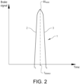
- Fig. 2 shows a curve illustrating the brake signal as a function of time during a braking operation.
- This brake signal curve 1 in Fig. 2 is an example that shows a near ideal braking curve.
- the start of the braking operation at T s can be identified by a first threshold value for the brake signal.
- the end of the braking operation at T E can be identified by a second threshold value for the brake signal.
- the measured brake signal decreases to an end value which is smaller than the second threshold value, the time point T E is set.
- the first threshold value and the second threshold value is the same.
- the braking operation is suitably defined as a single braking operation provided that the time period between the end value at T E of the braking operation and a start value at Ts of a second subsequent braking operation is longer than a predetermined time period.
- a predetermined time period can be for example 0.5 seconds.
- the brake signal curve 1 has a maximum brake signal peak BS MAX at the time point T BSMAX .
- the method suitably comprises identifying the maximum signal brake peak BS MAX that occurred during the braking operation and dividing the brake signal curve into a first portion 2 of the brake signal curve 1 before the maximum brake signal peak BS MAX and a second portion 3 of the brake signal curve 1 after the maximum brake signal peak BS MAX .
- the first portion 2 of the brake signal curve 1 can be evaluated with respect to a first braking parameter and the second portion 3 of the brake signal curve 1 can be evaluated with respect to a second braking parameter.
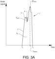
- Figs. 3A and 3B show examples of brake signal curves where the braking during the first part of the braking operation before the maximum brake signal peak BS MAX is not optimal. More particularly, the braking according to the brake signal curve in Fig. 3A is considered better than the braking according to the brake signal curve in Fig. 3B , and the braking according to the brake signal curve in Fig. 2 is considered better than the braking according to the brake signal curve in Fig. 3A .
- the first braking parameter can be an area under the brake signal curve 1.
- the first braking parameter is the area under the brake signal curve, between Ts and T BSMAX , wherein the method comprises comparing the area under the brake signal curve in the first portion 2 of the brake signal curve 1 with a reference area, and determining the quality of the braking operation by a ratio between the brake signal curve area and the reference area.
- the area under the first portion 2 of the brake signal curve 1 is denoted A 1 .
- the reference area A 1R is created by a horizontal line 4 extending from a local brake signal peak (local maxima) 5 to the brake signal curve, thereby taking any negative derivative away from the first portion 2 of the brake signal curve 1.
- the reference area A 1R is suitably the area A 1 under the measured brake signal curve plus an added area A ADD under the horizontal line 4.
- the added area A ADD is indicated by dots.
- the area under the first portion 2 of the brake signal curve 1 is denoted A 1 '.
- the reference area A 1R ' is created by two horizontal lines 4, 4' each extending from a local brake signal peak (local maxima) 5, 5' to the brake signal curve, thereby taking any negative derivative away from the first portion 2 of the brake signal curve 1.
- the reference area A 1R ' is suitably the area A 1 ' under the measured brake signal curve plus the added area A ADD under the horizontal line 4 plus another added area A ADD ' under the horizontal line 4'.
- the added areas A ADD and A ADD ' are indicated by dots.
- Figs. 4A and 4B show examples of brake signal curves where the braking during the second part of the braking operation after the maximum brake signal peak BS MAX is not optimal. More particularly, the braking according to the brake signal curve in Fig. 4A is considered better than the braking according to the brake signal curve in Fig. 4B , and the braking according to the brake signal curve in Fig. 2 is considered better than the braking according to the brake signal curve in Fig. 4A .
- the second braking parameter can be an area under the brake signal curve.
- the second braking parameter is an area under the brake signal curve, between T BSMAX and T E , wherein the method comprises comparing the area under the brake signal curve in the second portion 3 of the brake signal curve with a reference area, and determining the quality of the braking operation by a ratio between the brake signal curve area and the reference area.
- the area under the second portion 3 of the brake signal curve 1 is denoted A 2 .
- the reference area A 2R is created by a horizontal line 6 extending from a local brake signal minimum (local minima) 7 to the brake signal curve, thereby taking any positive derivative away from the brake signal curve.
- the reference area A 2R is suitably the area A 2 under the measured brake signal curve minus a removed area A 2REM above the horizontal line 6.
- the removed area A 2REM is indicated by dots.
- the area under the second portion 3 of the brake signal curve 1 is denoted A 2 '.
- the reference area A 2R ' is created by two horizontal lines 6, 6' each extending from a local brake signal minimum (local minima) 7, 7' to the brake signal curve, thereby taking any positive derivative away from the second portion 3 of the brake signal curve 1.
- the reference area A 2R ' is suitably the area A 2 ' under the measured brake signal curve minus the removed area A 2REM above the horizontal line 6 minus a removed area A 2REM ' above the horizontal line 6'.
- the removed areas A 2REM and A 2REM ' are indicated by dots.
- the first parameter can be the derivative of the brake signal curve, and the presence of a negative derivative of the first portion of the brake signal curve is defined as lowering the quality of the braking operation, or the first parameter is the shape of brake signal curve, and the presence of an extreme point, local minima or local maxima, of the first portion of the brake signal curve is defined as lowering the quality of the braking operation.
- the second parameter can be the derivative of the brake signal curve, and the presence of a positive derivative of the second portion of the brake signal curve is defined as lowering the quality of the braking operation, or the second parameter is the shape of brake signal curve, and the presence of an extreme point, local maxima or minima, of the second portion of the brake signal curve is defined as lowering the quality of the braking operation.
- a large positive derivative immediately before a local maxima is defined as lower quality of the braking operation than a small positive derivative immediately before a local maxima.
- Fig. 5 shows a schematic view of an arrangement 100 for providing driver feedback to a driver of a vehicle.
- the arrangement comprises a control unit 110 receiving and recording a brake signal 120 as a function of time during a braking operation.
- the arrangement 100 suitably comprises a sensor 130 for providing the brake signal 120 to the control unit 110. For example, when a brake pedal of the vehicle is depressed, the position of the brake pedal can be measured by the sensor 130 and a corresponding brake signal 120 can be generated as a function of the brake pedal position.
- the control unit 110 is arranged to create a brake signal curve based on the received brake signal 120 and evaluate the brake signal curve with respect to a braking parameter for determining the quality of the braking operation.
- the evaluation of the brake signal curve can be performed as previously described hereinabove with reference to the method for providing driver feedback to a driver of a vehicle.
- control unit 110 is arranged to provide the driver feedback based on the determined quality of the braking operation to a driver information system 140 of the vehicle.
- the arrangement 100 suitably comprises such a driver information system 140 having a display 150 showing the driver feedback in the vehicle.
- driver feedback may comprise quantified performance values and/or coaching tips for the braking operation.
- the control unit 110 may comprise one or more microprocessors and/or one or more memory devices or any other components for executing computer programs or receiving and/or sending control signals for providing the driver feedback. Particularly, the control unit is preferably provided with a computer program comprising program code means for performing all steps of any embodiment of the method described herein.
- the control unit can be a separate component or be integrated in another controller of the vehicle.
Landscapes
- Engineering & Computer Science (AREA)
- Transportation (AREA)
- Mechanical Engineering (AREA)
- Regulating Braking Force (AREA)
Abstract
The invention relates to a method for providing driver feedback to a driver of a vehicle. The method comprises receiving (10) a brake signal and recording the brake signal as a function of time, which brake signal correlates to or is a direct measure of a brake torque provided by a brake of the vehicle during a braking operation, creating (20) a brake signal curve based on the received brake signal and evaluating (30) the brake signal curve with respect to a braking parameter for determining the quality of the braking operation, and providing (40) the driver feedback based on the determined quality of the braking operation to a driver information system of the vehicle.
Description
- The invention relates to a method and an arrangement for providing driver feedback to a driver of a vehicle, particularly for a driver driving a vehicle on a racetrack.
- When driving a vehicle the smoothness of the braking performed by the driver is important in order to apply brake torque in an adequate way for the current braking operation. An optimized working point with respect to the slip ratio of the tires is desired, both for maintaining the highest grip or friction between the tires and the road, and for avoiding unnecessary wear on the tires.
- An objective of the invention is to provide a method for providing driver feedback to a driver of a vehicle, by which method the driver can learn and improve the way of braking the vehicle for optimizing the braking operation.
- The objective is achieved by a method for providing driver feedback to a driver of a vehicle, wherein the method comprises receiving a brake signal and recording the brake signal as a function of time, which brake signal correlates to or is a direct measure of a brake torque provided by a brake of the vehicle during a braking operation, creating a brake signal curve based on the received brake signal and evaluating the brake signal curve with respect to a braking parameter for determining the quality of the braking operation, and providing the driver feedback based on the determined quality of the braking operation to a driver information system of the vehicle.
- The invention is based on the insight that by such a method, a quantified value of the quality of the braking operation can be provided to the driver, preferably immediately after the braking operation has been performed. The smoothness of the braking operation can be evaluated and the braking operation can be given a score, and the braking operation score and/or coaching tips based on the braking operation score can be presented to the driver by the driver information system.
- The brake signal can be provided in various ways, as long as the measured and received brake signal correlates to or is a direct measure of the brake torque, such as from a sensor measuring the travel or depression of a brake pedal of the vehicle, from a sensor measuring a hydraulic brake pressure of a brake of the vehicle, from a control unit providing a signal for requested brake force or brake torque of a brake of the vehicle, or from a sensor measuring the current brake force or brake torque applied.
- According to one embodiment, the method comprises identifying a maximum brake signal peak that occurred during the braking operation and dividing the brake signal curve into a first portion of the brake signal curve before the maximum brake signal peak and a second portion of the brake signal curve after the maximum brake signal peak, and evaluating the first portion of the brake signal curve with respect to a first braking parameter and the second portion of the brake signal curve with respect to a second braking parameter. Hereby, it can be assessed if the driver was using the available grip in a corner of the racetrack, and if the applied brake torque had to be corrected. The result of the assessment can be used for giving detailed feedback to the driver about the braking operation and what changes in braking behaviour would improve the braking performance.
- According to a further embodiment, the first braking parameter is an area under the brake signal curve and/or the second parameter is an area under the brake signal curve. Hereby, a quantitative parameter enabling the provision of a qualitative analysis result for the first portion of the braking operation and/or the second portion of the braking operation can be achieved.
- According to a further embodiment, the first braking parameter is an area under the brake signal curve, wherein the method comprises comparing the area under the brake signal curve in the first portion of the brake signal curve with a reference area, and determining the quality of the braking operation by a ratio between the brake signal curve area and the reference area, wherein the ratio is ≤1, and the bigger ratio, the higher quality of the braking operation. Hereby, a quantitative parameter that can be used to give a qualitative assessment of the braking operation, which corresponds to the tendency of the driver to make corrections to the applied brake torque in the first portion of the braking operation, can be achieved.
- According to a further embodiment, the second braking parameter is an area under the brake signal curve, wherein the method comprises comparing the area under the brake signal curve in the second portion of the brake signal curve with a reference area, and determining the quality of the braking operation by a ratio between the brake signal curve area and the reference area, wherein the ratio is ≥1, and the smaller ratio, the higher quality of the braking operation. Hereby, a quantitative parameter that can be used to give a qualitative assessment of the braking operation, which corresponds to the tendency of the driver to make corrections to the applied brake torque in the second portion of the braking operation, can be achieved. A ratio above 1 can also indicate that the driver did not fully utilise the available grip in the first portion of the braking operation.
- According to a further embodiment, the first parameter is the derivative of the brake signal curve, and the presence of a negative derivative of the first portion of the brake signal curve is defined as lowering the quality of the braking operation. Hereby, mapping where the applied brake torque was decreasing before the maximum brake signal peak, which corresponds to local maxima in the first portion of the braking operation, can be performed. Such a local maxima would result in a longer application of the brake torque which in turn leads to an increased lap time when driving on a racetrack.
- According to a further embodiment, the first parameter is the shape of brake signal curve, and the presence of a local maxima or local minima of the first portion of the brake signal curve is defined as lowering the quality of the braking operation. Such a local maxima or minima would result in a longer application of the brake torque which in turn leads to an increased lap time when driving on a racetrack.
- According to a further embodiment, the second parameter is the derivative of the brake signal curve, and the presence of a positive derivative of the second portion of the brake signal curve is defined as lowering the quality of the braking operation. Hereby, mapping where the applied brake torque was increasing after the maximum brake signal peak, which corresponds to local maxima in the second portion of the braking operation, can be performed. Such a local maxima would result in a longer application of the brake torque which in turn leads to an increased lap time when driving on a racetrack.
- According to a further embodiment, the second parameter is the shape of brake signal curve, and the presence of a local maxima or local minima of the second portion of the brake signal curve is defined as lowering the quality of the braking operation. Such a local maxima or minima would result in a longer application of the brake torque which in turn leads to an increased lap time when driving on a racetrack.
- According to a further embodiment, the second parameter is the shape of brake signal curve, and the presence of a large positive derivative immediately before a local maxima of the second portion of the brake signal curve is defined as lower quality of the braking operation than a small positive derivative immediately before a local maxima of the second portion of the brake signal curve. Hereby, the quality of the braking operation can be further evaluated since small corrections to the applied brake torque may be necessary when the driver has used the available grip in the first portion of the braking operation.
- According to a further embodiment, the method comprises identifying a start of the braking operation when the measured brake signal increases to a start value exceeding a first threshold value and an end of the braking operation when the measured brake signal decreases to an end value which is smaller than a second threshold value. For example, the first threshold value and the second threshold value can be the same. Hereby, where in time the braking operation was performed can be identified.
- According to a further embodiment, the method comprises defining the braking operation as a single braking operation provided that the time period between the end value of the braking operation and a start value of a second subsequent braking operation is longer than a predetermined time period. Hereby, checking for very small time differences between periods of applied brake torque, which impact the driving with respect to one and the same corner of the racetrack and should be considered as the same braking operation, can be performed. This ensures that a coherent braking operation is considered in the analysis, which is more intuitive for the driver when to adjust the braking behaviour to improve the braking performance.
- According to a further embodiment, the method comprises showing the driver feedback comprising a quantified performance value and/or coaching tip for the braking operation on a display of the driver information system. Hereby, the driver can receive driver feedback in a suitable way while driving the vehicle. By providing both quantified performance values and coaching tips, such as a description of how the braking operation can be improved to reduce the lap time when driving on a racetrack, the driver can adjust the braking behaviour and immediately see the result thereof.
- According to another aspect of the invention, the invention relates to an arrangement for providing driver feedback to a driver of a vehicle, wherein the arrangement comprises a control unit receiving and recording a brake signal as a function of time, which brake signal correlates to or is a direct measure of a brake torque provided by a brake of the vehicle during a braking operation, the control unit being arranged to create a brake signal curve based on the received brake signal and evaluate the brake signal curve with respect to a braking parameter for determining the quality of the braking operation, and to provide the driver feedback based on the determined quality of the braking operation to a driver information system of the vehicle.
- The invention is based on the insight that by such an arrangement, a quantified value of the quality of the braking operation can be provided to the driver, preferably immediately after the braking operation has been performed. The smoothness of the braking operation can be evaluated and the braking operation can be given a score, and the braking operation score and/or coaching tips based on the braking operation score can be presented to the driver by the driver information system.
- According to one embodiment of the arrangement, the control unit is arranged to identify a maximum brake signal peak that occurred during the braking operation and divide the brake signal curve into a first portion of the brake signal curve before the maximum brake signal peak and a second portion of the brake signal curve after the maximum brake signal peak, and to evaluate the first portion of the brake signal curve with respect to a first braking parameter and the second portion of the brake signal curve with respect to a second braking parameter. Hereby, it can be assessed if the driver was using the available grip in a corner of the racetrack, and if the applied brake torque had to be corrected. The result of the assessment can be used for giving detailed feedback to the driver about the braking operation and what changes in braking behaviour would improve the braking performance.
- According to a further embodiment of the arrangement, the first braking parameter is an area under the brake signal curve and/or the second parameter is an area under the brake signal curve. Hereby, a quantitative parameter enabling the provision of a qualitative analysis result for the first portion of the braking operation and/or the second portion of the braking operation can be achieved.
- According to a further embodiment of the arrangement, the first braking parameter is an area under the brake signal curve, and the control unit is arranged to compare the area under the brake signal curve in the first portion of the brake signal curve with a reference area, and determining the quality of the braking operation by a ratio between the brake signal curve area and the reference area, wherein the ratio is ≤1, and the bigger ratio, the higher quality of the braking operation. Hereby, a quantitative parameter that can be used to give a qualitative assessment of the braking operation, which corresponds to the tendency of the driver to make corrections to the applied brake torque in the first portion of the braking operation, can be achieved.
- According to a further embodiment of the arrangement, the second braking parameter is an area under the brake signal curve, and the control unit is arranged to compare the area under the brake signal curve in the second portion of the brake signal curve with a reference area, and determining the quality of the braking operation by a ratio between the brake signal curve area and the reference area, wherein the ratio is ≥1, and the smaller ratio, the higher quality of the braking operation. Hereby, a quantitative parameter that can be used to give a qualitative assessment of the braking operation, which corresponds to the tendency of the driver to make corrections to the applied brake torque in the second portion of the braking operation, can be achieved. A ratio above 1 can also indicate that the driver did not fully utilise the available grip in the first portion of the braking operation.
- According to a further embodiment of the arrangement, the first parameter is the derivative of the brake signal curve, and the presence of a negative derivative of the first portion of the brake signal curve is defined as lowering the quality of the braking operation. Hereby, mapping where the applied brake torque was decreasing before the maximum brake signal peak, which corresponds to local maxima in the first portion of the braking operation, can be performed. Such a local maxima would result in a longer application of the brake torque which in turn leads to an increased lap time when driving on a racetrack.
- According to a further embodiment of the arrangement, the second parameter is the derivative of the brake signal curve, and the presence of a positive derivative of the second portion of the brake signal curve is defined as lowering the quality of the braking operation. Hereby, mapping where the applied brake torque was increasing after the maximum brake signal peak, which corresponds to local maxima in the second portion of the braking operation, can be performed. Such a local maxima would result in a longer application of the brake torque which in turn leads to an increased lap time when driving on a racetrack.
- Further advantages and advantageous features of the invention are disclosed in the following description and in the claims.
- With reference to the appended drawings, below follows a more detailed description of embodiments of the invention cited as examples.
- In the drawings:
-
Fig. 1 is a flow chart of a method for providing driver feedback to a driver of a vehicle, -
Fig. 2 is a curve illustrating a brake signal as a function of time during a braking operation. -
Figs. 3A and3B are brake signal curves where the braking during a first part of the braking operation is not optimal, -
Figs. 4A and4B are brake signal curves where the braking during a second part of the braking operation is not optimal, and -
Fig. 5 is a schematic view of an arrangement for providing driver feedback to a driver of a vehicle. -
Fig. 1 is a flow chart showing a method for providing driver feedback to a driver of a vehicle. - While driving the vehicle a brake signal is received 10. When the vehicle is braked such a signal is generated. For example, when a brake pedal of the vehicle is depressed, the position of the brake pedal can be measured and a corresponding brake signal can be generated as a function of the brake pedal position. In this way, the brake signal will indicate to what extent the vehicle is braked, i.e. the brake signal correlates to or is a direct measure of the brake torque applied at the current time point.
- The brake signal is recorded as a function of time during a braking operation, and a brake signal curve based on the received brake signal is created 20. By continuously recording the magnitude of the brake signal as a function of time, during the braking operation, the brake signal curve generated will provide information about the braking behaviour of the driver of the vehicle. Then, the brake signal curve is evaluated 30 with respect to a braking parameter for determining the quality of the braking operation.
- Finally, the driver feedback based on the determined quality of the braking operation is provided 40 to a driver information system of the vehicle by which system the driver feedback can be presented to the driver of the vehicle. Such a driver information system suitably comprises a display showing the driver feedback by way of texted coaching tips, pictures, diagrams, messages and/or numbers or any other appropriate form.
-
Fig. 2 shows a curve illustrating the brake signal as a function of time during a braking operation. - This
brake signal curve 1 inFig. 2 is an example that shows a near ideal braking curve. At the timepoint Ts the braking operation starts and at the timepoint TE the braking operation ends. The start of the braking operation at Ts can be identified by a first threshold value for the brake signal. When the measured brake signal increases to a start value exceeding the first threshold value, the time point Ts is set. The end of the braking operation at TE can be identified by a second threshold value for the brake signal. When the measured brake signal decreases to an end value which is smaller than the second threshold value, the time point TE is set. As an example only, the first threshold value and the second threshold value is the same. - The braking operation is suitably defined as a single braking operation provided that the time period between the end value at TE of the braking operation and a start value at Ts of a second subsequent braking operation is longer than a predetermined time period. Such a predetermined time period can be for example 0.5 seconds.
- As also illustrated in
Fig. 2 , thebrake signal curve 1 has a maximum brake signal peak BSMAX at the time point TBSMAX. The method suitably comprises identifying the maximum signal brake peak BSMAX that occurred during the braking operation and dividing the brake signal curve into afirst portion 2 of thebrake signal curve 1 before the maximum brake signal peak BSMAX and asecond portion 3 of thebrake signal curve 1 after the maximum brake signal peak BSMAX. - Thereafter, the
first portion 2 of thebrake signal curve 1 can be evaluated with respect to a first braking parameter and thesecond portion 3 of thebrake signal curve 1 can be evaluated with respect to a second braking parameter. -
Figs. 3A and3B show examples of brake signal curves where the braking during the first part of the braking operation before the maximum brake signal peak BSMAX is not optimal. More particularly, the braking according to the brake signal curve inFig. 3A is considered better than the braking according to the brake signal curve inFig. 3B , and the braking according to the brake signal curve inFig. 2 is considered better than the braking according to the brake signal curve inFig. 3A . - The first braking parameter can be an area under the
brake signal curve 1. In the embodiment examples inFigs. 3A and3B , the first braking parameter is the area under the brake signal curve, between Ts and TBSMAX, wherein the method comprises comparing the area under the brake signal curve in thefirst portion 2 of thebrake signal curve 1 with a reference area, and determining the quality of the braking operation by a ratio between the brake signal curve area and the reference area. - With reference to
Fig. 3A , the area under thefirst portion 2 of thebrake signal curve 1 is denoted A1. The reference area A1R is created by ahorizontal line 4 extending from a local brake signal peak (local maxima) 5 to the brake signal curve, thereby taking any negative derivative away from thefirst portion 2 of thebrake signal curve 1. In other words, the reference area A1R is suitably the area A1 under the measured brake signal curve plus an added area AADD under thehorizontal line 4. The added area AADD is indicated by dots. The ratio Q=A1/A1R is ≤1, and the bigger ratio Q, the higher quality of the braking operation. - With reference to
Fig. 3B , the area under thefirst portion 2 of thebrake signal curve 1 is denoted A1'. The reference area A1R' is created by twohorizontal lines 4, 4' each extending from a local brake signal peak (local maxima) 5, 5' to the brake signal curve, thereby taking any negative derivative away from thefirst portion 2 of thebrake signal curve 1. In other words, the reference area A1R' is suitably the area A1' under the measured brake signal curve plus the added area AADD under thehorizontal line 4 plus another added area AADD' under the horizontal line 4'. The added areas AADD and AADD' are indicated by dots. The ratio Q=A1'/A1R' is ≤1, and the bigger ratio Q, the higher quality of the braking operation. -
Figs. 4A and4B show examples of brake signal curves where the braking during the second part of the braking operation after the maximum brake signal peak BSMAX is not optimal. More particularly, the braking according to the brake signal curve inFig. 4A is considered better than the braking according to the brake signal curve inFig. 4B , and the braking according to the brake signal curve inFig. 2 is considered better than the braking according to the brake signal curve inFig. 4A . - The second braking parameter can be an area under the brake signal curve. In
Figs. 4A and4B , the second braking parameter is an area under the brake signal curve, between TBSMAX and TE, wherein the method comprises comparing the area under the brake signal curve in thesecond portion 3 of the brake signal curve with a reference area, and determining the quality of the braking operation by a ratio between the brake signal curve area and the reference area. - With reference to
Fig. 4A , the area under thesecond portion 3 of thebrake signal curve 1 is denoted A2. The reference area A2R is created by ahorizontal line 6 extending from a local brake signal minimum (local minima) 7 to the brake signal curve, thereby taking any positive derivative away from the brake signal curve. In other words, the reference area A2R is suitably the area A2 under the measured brake signal curve minus a removed area A2REM above thehorizontal line 6. The removed area A2REM is indicated by dots. The ratio Q=A2/A2R is ≥1, and the smaller ratio Q, the higher quality of the braking operation. - With reference to
Fig. 4B , the area under thesecond portion 3 of thebrake signal curve 1 is denoted A2'. The reference area A2R' is created by twohorizontal lines second portion 3 of thebrake signal curve 1. In other words, the reference area A2R' is suitably the area A2' under the measured brake signal curve minus the removed area A2REM above thehorizontal line 6 minus a removed area A2REM' above thehorizontal line 6'. The removed areas A2REM and A2REM' are indicated by dots. The ratio Q=A2'/A2R' is ≥1, and the smaller ratio Q, the higher quality of the braking operation. - Alternatively, the first parameter can be the derivative of the brake signal curve, and the presence of a negative derivative of the first portion of the brake signal curve is defined as lowering the quality of the braking operation, or the first parameter is the shape of brake signal curve, and the presence of an extreme point, local minima or local maxima, of the first portion of the brake signal curve is defined as lowering the quality of the braking operation.
- In the same way, the second parameter can be the derivative of the brake signal curve, and the presence of a positive derivative of the second portion of the brake signal curve is defined as lowering the quality of the braking operation, or the second parameter is the shape of brake signal curve, and the presence of an extreme point, local maxima or minima, of the second portion of the brake signal curve is defined as lowering the quality of the braking operation. Further, in the second portion of the brake signal curve, a large positive derivative immediately before a local maxima is defined as lower quality of the braking operation than a small positive derivative immediately before a local maxima.
-
Fig. 5 shows a schematic view of anarrangement 100 for providing driver feedback to a driver of a vehicle. - The arrangement comprises a
control unit 110 receiving and recording abrake signal 120 as a function of time during a braking operation. Thearrangement 100 suitably comprises asensor 130 for providing thebrake signal 120 to thecontrol unit 110. For example, when a brake pedal of the vehicle is depressed, the position of the brake pedal can be measured by thesensor 130 and acorresponding brake signal 120 can be generated as a function of the brake pedal position. ` - The
control unit 110 is arranged to create a brake signal curve based on the receivedbrake signal 120 and evaluate the brake signal curve with respect to a braking parameter for determining the quality of the braking operation. The evaluation of the brake signal curve can be performed as previously described hereinabove with reference to the method for providing driver feedback to a driver of a vehicle. - Further, the
control unit 110 is arranged to provide the driver feedback based on the determined quality of the braking operation to adriver information system 140 of the vehicle. Thearrangement 100 suitably comprises such adriver information system 140 having adisplay 150 showing the driver feedback in the vehicle. Such driver feedback may comprise quantified performance values and/or coaching tips for the braking operation. - The
control unit 110 may comprise one or more microprocessors and/or one or more memory devices or any other components for executing computer programs or receiving and/or sending control signals for providing the driver feedback. Particularly, the control unit is preferably provided with a computer program comprising program code means for performing all steps of any embodiment of the method described herein. - The control unit can be a separate component or be integrated in another controller of the vehicle.
- It is to be understood that the present invention is not limited to the embodiments described above and illustrated in the drawings; rather, the skilled person will recognize that many changes and modifications may be made within the scope of the appended claims.
Claims (20)
- A method for providing driver feedback to a driver of a vehicle, characterized by receiving (10) a brake signal and recording the brake signal as a function of time, which brake signal correlates to or is a direct measure of a brake torque provided by a brake of the vehicle during a braking operation, creating (20) a brake signal curve based on the received brake signal and evaluating (30) the brake signal curve with respect to a braking parameter for determining the quality of the braking operation, and providing (40) the driver feedback based on the determined quality of the braking operation to a driver information system of the vehicle.
- A method according to claim 1, characterized by identifying a maximum brake signal peak (BSMAX) that occurred during the braking operation and dividing the brake signal curve into a first portion (2) of the brake signal curve before the maximum brake signal peak and a second portion (3) of the brake signal curve after the maximum brake signal peak, and evaluating the first portion of the brake signal curve with respect to a first braking parameter and the second portion of the brake signal curve with respect to a second braking parameter.
- A method according to claim 2, wherein the first braking parameter is an area (A1) under the brake signal curve and/or the second parameter is an area (A2) under the brake signal curve (1).
- A method according to claim 2, wherein the first braking parameter is an area under the brake signal curve, wherein the method comprises comparing the area (A1) under the brake signal curve in the first portion of the brake signal curve with a reference area (A1R), and determining the quality of the braking operation by a ratio (Q=A1/A1R) between the brake signal curve area and the reference area, wherein the ratio is ≤1, and the bigger ratio (Q), the higher quality of the braking operation.
- A method according to claim 2 or 4, wherein the second braking parameter is an area under the brake signal curve, wherein the method comprises comparing the area (A2) under the brake signal curve in the second portion of the brake signal curve with a reference area (A2R), and determining the quality of the braking operation by a ratio (Q=A2/A2R) between the brake signal curve area and the reference area, wherein the ratio is ≥1, and the smaller ratio (Q), the higher quality of the braking operation.
- A method according to claim 2, wherein the first parameter is the derivative of the brake signal curve (1), and the presence of a negative derivative of the first portion (2) of the brake signal curve is defined as lowering the quality of the braking operation.
- A method according to claim 2, wherein the first parameter is the shape of brake signal curve, and the presence of a local maxima (5) or local minima of the first portion (2) of the brake signal curve (1) is defined as lowering the quality of the braking operation.
- A method according to claim 2 or 6 or 7, wherein the second parameter is the derivative of the brake signal curve (1), and the presence of a positive derivative of the second portion (3) of the brake signal curve is defined as lowering the quality of the braking operation.
- A method according to claim 2 or 6 or 7, wherein the second parameter is the shape of brake signal curve, and the presence of a local maxima or local minima (7) of the second portion (3) of the brake signal curve (1) is defined as lowering the quality of the braking operation.
- A method according to claim 2 or 7, wherein the second parameter is the shape of brake signal curve, and the presence of a large positive derivative immediately before a local maxima of the second portion (3) of the brake signal curve (1) is defined as lower quality of the braking operation than a small positive derivative immediately before a local maxima of the second portion (3) of the brake signal curve (2).
- A method according to any preceding claim, characterized by identifying a start of the braking operation when the measured brake signal increases to a start value exceeding a first threshold value and an end of the braking operation when the measured brake signal decreases to an end value which is smaller than a second threshold value.
- A method according to claim 11, characterized by defining the braking operation as a single braking operation provided that the time period between the end value of the braking operation and a start value of a second subsequent braking operation is longer than a predetermined time period.
- A method according to any preceding claim, characterized by showing the driver feedback comprising a quantified performance value and/or coaching tip for the braking operation on a display (150) of the driver information system (140).
- An arrangement (100) for providing driver feedback to a driver of a vehicle, characterized in that the arrangement comprises a control unit (110) receiving and recording a brake signal (120) as a function of time, which brake signal correlates to or is a direct measure of a brake torque provided by a brake of the vehicle during a braking operation, the control unit (110) being arranged to create a brake signal curve based on the received brake signal and evaluate the brake signal curve with respect to a braking parameter for determining the quality of the braking operation, and to provide the driver feedback based on the determined quality of the braking operation to a driver information system (140) of the vehicle.
- An arrangement according to claim 14, characterized ]in that the control unit (110) is arranged to identify a maximum brake signal peak (BSMAX) that occurred during the braking operation and divide the brake signal curve (1) into a first portion (2) of the brake signal curve before the maximum brake signal peak and a second portion (3) of the brake signal curve after the maximum brake signal peak, and to evaluate the first portion of the brake signal curve with respect to a first braking parameter and the second portion of the brake signal curve with respect to a second braking parameter.
- An arrangement according to claim 15, characterized in that the first braking parameter is an area (A1) under the brake signal curve and/or the second parameter is an area (A2) under the brake signal curve.
- An arrangement according to claim 15, characterized in that the first braking parameter is an area under the brake signal curve, and the control unit is arranged to compare the area (A1) under the brake signal curve in the first portion of the brake signal curve with a reference area (A1R), and determining the quality of the braking operation by a ratio (Q=A1/A1R) between the brake signal curve area and the reference area, wherein the ratio is ≤1, and the bigger ratio (Q), the higher quality of the braking operation.
- An arrangement according to claim 15 or 17, characterized in that the second braking parameter is an area under the brake signal curve, and the control unit is arranged to compare the area (A2) under the brake signal curve in the second portion of the brake signal curve with a reference area (A2R), and determining the quality of the braking operation by a ratio (Q=A2/A2R) between the brake signal curve area and the reference area, wherein the ratio is ≥1, and the smaller ratio (Q), the higher quality of the braking operation.
- An arrangement according to claim 15, characterized in that the first parameter is the derivative of the brake signal curve, and the presence of a negative derivative of the first portion of the brake signal curve is defined as lowering the quality of the braking operation.
- An arrangement according to claim 15 or 19, characterized in that the second parameter is the derivative of the brake signal curve, and the presence of a positive derivative of the second portion of the brake signal curve is defined as lowering the quality of the braking operation.
Priority Applications (2)
| Application Number | Priority Date | Filing Date | Title |
|---|---|---|---|
| EP23194119.6A EP4516607A1 (en) | 2023-08-29 | 2023-08-29 | A method for providing driver feedback |
| PCT/CN2024/114113 WO2025044918A1 (en) | 2023-08-29 | 2024-08-23 | A method for providing driver feedback |
Applications Claiming Priority (1)
| Application Number | Priority Date | Filing Date | Title |
|---|---|---|---|
| EP23194119.6A EP4516607A1 (en) | 2023-08-29 | 2023-08-29 | A method for providing driver feedback |
Publications (1)
| Publication Number | Publication Date |
|---|---|
| EP4516607A1 true EP4516607A1 (en) | 2025-03-05 |
Family
ID=87889777
Family Applications (1)
| Application Number | Title | Priority Date | Filing Date |
|---|---|---|---|
| EP23194119.6A Withdrawn EP4516607A1 (en) | 2023-08-29 | 2023-08-29 | A method for providing driver feedback |
Country Status (2)
| Country | Link |
|---|---|
| EP (1) | EP4516607A1 (en) |
| WO (1) | WO2025044918A1 (en) |
Citations (3)
| Publication number | Priority date | Publication date | Assignee | Title |
|---|---|---|---|---|
| US20020072836A1 (en) * | 2000-07-08 | 2002-06-13 | Reinhard Weiberle | Method and device for evaluating a sensor signal |
| US20080042489A1 (en) * | 2006-08-17 | 2008-02-21 | Lewis Donald J | Driver Feedback to Improve Vehicle Performance |
| DE102021210226A1 (en) * | 2021-09-15 | 2023-03-16 | Volkswagen Aktiengesellschaft | Method for informing a driver of a motor vehicle about an error associated with a brake system of the motor vehicle |
-
2023
- 2023-08-29 EP EP23194119.6A patent/EP4516607A1/en not_active Withdrawn
-
2024
- 2024-08-23 WO PCT/CN2024/114113 patent/WO2025044918A1/en active Pending
Patent Citations (3)
| Publication number | Priority date | Publication date | Assignee | Title |
|---|---|---|---|---|
| US20020072836A1 (en) * | 2000-07-08 | 2002-06-13 | Reinhard Weiberle | Method and device for evaluating a sensor signal |
| US20080042489A1 (en) * | 2006-08-17 | 2008-02-21 | Lewis Donald J | Driver Feedback to Improve Vehicle Performance |
| DE102021210226A1 (en) * | 2021-09-15 | 2023-03-16 | Volkswagen Aktiengesellschaft | Method for informing a driver of a motor vehicle about an error associated with a brake system of the motor vehicle |
Non-Patent Citations (1)
| Title |
|---|
| HERMANSDORFER LEONHARD ET AL: "Benchmarking of a software stack for autonomous racing against a professional human race driver", 2020 FIFTEENTH INTERNATIONAL CONFERENCE ON ECOLOGICAL VEHICLES AND RENEWABLE ENERGIES (EVER), IEEE, 10 September 2020 (2020-09-10), pages 1 - 8, XP033849699, DOI: 10.1109/EVER48776.2020.9242926 * |
Also Published As
| Publication number | Publication date |
|---|---|
| WO2025044918A1 (en) | 2025-03-06 |
Similar Documents
| Publication | Publication Date | Title |
|---|---|---|
| US20150321649A1 (en) | Method for controlling braking force of brake according to velocity | |
| CN108297860A (en) | A kind of gas pedal aperture parsing control method, apparatus and system | |
| CN110723136A (en) | Method and system for activating automatic parking function, storage medium and vehicle | |
| DE102012210574A1 (en) | System and method for controlling the creep torque of a vehicle | |
| EP1719676A1 (en) | System and method for tire/road friction estimation | |
| EP4516607A1 (en) | A method for providing driver feedback | |
| JP2020531350A (en) | Controls and methods for driving the vehicle deceleration device of the vehicle | |
| WO2010137136A1 (en) | Vehicle | |
| US11242058B2 (en) | Method for detecting a driving state of a vehicle | |
| CN103328865A (en) | A method for selecting a starting gear | |
| KR102777761B1 (en) | System and mathod for removing rust of brake system | |
| JP2004538192A (en) | Method and apparatus for determining characteristic values of wheel brakes | |
| US20100280724A1 (en) | Methods and systems for calibrating braking systems and controlling braking in vehicles | |
| US10077032B2 (en) | Method and system for reducing brake drag | |
| KR20190067098A (en) | Method and control device for operating an electric vehicle or a hybrid vehicle | |
| JP4096881B2 (en) | Vehicle speed control device | |
| CN116853014A (en) | Transmission system protection method, device and vehicle | |
| KR20160091699A (en) | Apparatus and method for estimating force in the electro mechanical brake system | |
| CN102887074A (en) | Vehicle safety control system and method | |
| CN110641428A (en) | Vehicle braking system and method for acquiring stroke of brake pedal | |
| US8972133B2 (en) | Method for detecting the clutch condition | |
| CN106976451B (en) | Vehicle dynamic stability control system and control method thereof | |
| JP5018732B2 (en) | Electric vehicle regeneration control device | |
| EP1375278A3 (en) | Automatic braking during vehicle creep control | |
| US11401904B2 (en) | Method for controlling an auto-stop start system of a vehicle |
Legal Events
| Date | Code | Title | Description |
|---|---|---|---|
| PUAI | Public reference made under article 153(3) epc to a published international application that has entered the european phase |
Free format text: ORIGINAL CODE: 0009012 |
|
| STAA | Information on the status of an ep patent application or granted ep patent |
Free format text: STATUS: REQUEST FOR EXAMINATION WAS MADE |
|
| 17P | Request for examination filed |
Effective date: 20230829 |
|
| AK | Designated contracting states |
Kind code of ref document: A1 Designated state(s): AL AT BE BG CH CY CZ DE DK EE ES FI FR GB GR HR HU IE IS IT LI LT LU LV MC ME MK MT NL NO PL PT RO RS SE SI SK SM TR |
|
| STAA | Information on the status of an ep patent application or granted ep patent |
Free format text: STATUS: THE APPLICATION IS DEEMED TO BE WITHDRAWN |
|
| 18D | Application deemed to be withdrawn |
Effective date: 20250906 |