EP4516595A1 - Steering wheel assembly - Google Patents
Steering wheel assembly Download PDFInfo
- Publication number
- EP4516595A1 EP4516595A1 EP23794985.4A EP23794985A EP4516595A1 EP 4516595 A1 EP4516595 A1 EP 4516595A1 EP 23794985 A EP23794985 A EP 23794985A EP 4516595 A1 EP4516595 A1 EP 4516595A1
- Authority
- EP
- European Patent Office
- Prior art keywords
- steering wheel
- clock spring
- wheel assembly
- spring part
- electronic device
- Prior art date
- Legal status (The legal status is an assumption and is not a legal conclusion. Google has not performed a legal analysis and makes no representation as to the accuracy of the status listed.)
- Pending
Links
Images

Classifications
-
- B—PERFORMING OPERATIONS; TRANSPORTING
- B62—LAND VEHICLES FOR TRAVELLING OTHERWISE THAN ON RAILS
- B62D—MOTOR VEHICLES; TRAILERS
- B62D1/00—Steering controls, i.e. means for initiating a change of direction of the vehicle
- B62D1/02—Steering controls, i.e. means for initiating a change of direction of the vehicle vehicle-mounted
- B62D1/04—Hand wheels
-
- B—PERFORMING OPERATIONS; TRANSPORTING
- B62—LAND VEHICLES FOR TRAVELLING OTHERWISE THAN ON RAILS
- B62D—MOTOR VEHICLES; TRAILERS
- B62D1/00—Steering controls, i.e. means for initiating a change of direction of the vehicle
- B62D1/02—Steering controls, i.e. means for initiating a change of direction of the vehicle vehicle-mounted
- B62D1/04—Hand wheels
- B62D1/10—Hubs; Connecting hubs to steering columns, e.g. adjustable
- B62D1/105—Non-rotatable hubs, e.g. the central part of the steering wheel not rotating
-
- B—PERFORMING OPERATIONS; TRANSPORTING
- B62—LAND VEHICLES FOR TRAVELLING OTHERWISE THAN ON RAILS
- B62D—MOTOR VEHICLES; TRAILERS
- B62D1/00—Steering controls, i.e. means for initiating a change of direction of the vehicle
- B62D1/02—Steering controls, i.e. means for initiating a change of direction of the vehicle vehicle-mounted
- B62D1/04—Hand wheels
- B62D1/046—Adaptations on rotatable parts of the steering wheel for accommodation of switches
-
- B—PERFORMING OPERATIONS; TRANSPORTING
- B60—VEHICLES IN GENERAL
- B60K—ARRANGEMENT OR MOUNTING OF PROPULSION UNITS OR OF TRANSMISSIONS IN VEHICLES; ARRANGEMENT OR MOUNTING OF PLURAL DIVERSE PRIME-MOVERS IN VEHICLES; AUXILIARY DRIVES FOR VEHICLES; INSTRUMENTATION OR DASHBOARDS FOR VEHICLES; ARRANGEMENTS IN CONNECTION WITH COOLING, AIR INTAKE, GAS EXHAUST OR FUEL SUPPLY OF PROPULSION UNITS IN VEHICLES
- B60K35/00—Instruments specially adapted for vehicles; Arrangement of instruments in or on vehicles
- B60K35/20—Output arrangements, i.e. from vehicle to user, associated with vehicle functions or specially adapted therefor
- B60K35/21—Output arrangements, i.e. from vehicle to user, associated with vehicle functions or specially adapted therefor using visual output, e.g. blinking lights or matrix displays
- B60K35/22—Display screens
-
- B—PERFORMING OPERATIONS; TRANSPORTING
- B60—VEHICLES IN GENERAL
- B60K—ARRANGEMENT OR MOUNTING OF PROPULSION UNITS OR OF TRANSMISSIONS IN VEHICLES; ARRANGEMENT OR MOUNTING OF PLURAL DIVERSE PRIME-MOVERS IN VEHICLES; AUXILIARY DRIVES FOR VEHICLES; INSTRUMENTATION OR DASHBOARDS FOR VEHICLES; ARRANGEMENTS IN CONNECTION WITH COOLING, AIR INTAKE, GAS EXHAUST OR FUEL SUPPLY OF PROPULSION UNITS IN VEHICLES
- B60K35/00—Instruments specially adapted for vehicles; Arrangement of instruments in or on vehicles
- B60K35/60—Instruments characterised by their location or relative disposition in or on vehicles
-
- B—PERFORMING OPERATIONS; TRANSPORTING
- B60—VEHICLES IN GENERAL
- B60R—VEHICLES, VEHICLE FITTINGS, OR VEHICLE PARTS, NOT OTHERWISE PROVIDED FOR
- B60R16/00—Electric or fluid circuits specially adapted for vehicles and not otherwise provided for; Arrangement of elements of electric or fluid circuits specially adapted for vehicles and not otherwise provided for
- B60R16/02—Electric or fluid circuits specially adapted for vehicles and not otherwise provided for; Arrangement of elements of electric or fluid circuits specially adapted for vehicles and not otherwise provided for electric constitutive elements
-
- B—PERFORMING OPERATIONS; TRANSPORTING
- B60—VEHICLES IN GENERAL
- B60R—VEHICLES, VEHICLE FITTINGS, OR VEHICLE PARTS, NOT OTHERWISE PROVIDED FOR
- B60R16/00—Electric or fluid circuits specially adapted for vehicles and not otherwise provided for; Arrangement of elements of electric or fluid circuits specially adapted for vehicles and not otherwise provided for
- B60R16/02—Electric or fluid circuits specially adapted for vehicles and not otherwise provided for; Arrangement of elements of electric or fluid circuits specially adapted for vehicles and not otherwise provided for electric constitutive elements
- B60R16/0207—Wire harnesses
-
- B—PERFORMING OPERATIONS; TRANSPORTING
- B60—VEHICLES IN GENERAL
- B60R—VEHICLES, VEHICLE FITTINGS, OR VEHICLE PARTS, NOT OTHERWISE PROVIDED FOR
- B60R16/00—Electric or fluid circuits specially adapted for vehicles and not otherwise provided for; Arrangement of elements of electric or fluid circuits specially adapted for vehicles and not otherwise provided for
- B60R16/02—Electric or fluid circuits specially adapted for vehicles and not otherwise provided for; Arrangement of elements of electric or fluid circuits specially adapted for vehicles and not otherwise provided for electric constitutive elements
- B60R16/023—Electric or fluid circuits specially adapted for vehicles and not otherwise provided for; Arrangement of elements of electric or fluid circuits specially adapted for vehicles and not otherwise provided for electric constitutive elements for transmission of signals between vehicle parts or subsystems
- B60R16/027—Electric or fluid circuits specially adapted for vehicles and not otherwise provided for; Arrangement of elements of electric or fluid circuits specially adapted for vehicles and not otherwise provided for electric constitutive elements for transmission of signals between vehicle parts or subsystems between relatively movable parts of the vehicle, e.g. between steering wheel and column
-
- B—PERFORMING OPERATIONS; TRANSPORTING
- B60—VEHICLES IN GENERAL
- B60K—ARRANGEMENT OR MOUNTING OF PROPULSION UNITS OR OF TRANSMISSIONS IN VEHICLES; ARRANGEMENT OR MOUNTING OF PLURAL DIVERSE PRIME-MOVERS IN VEHICLES; AUXILIARY DRIVES FOR VEHICLES; INSTRUMENTATION OR DASHBOARDS FOR VEHICLES; ARRANGEMENTS IN CONNECTION WITH COOLING, AIR INTAKE, GAS EXHAUST OR FUEL SUPPLY OF PROPULSION UNITS IN VEHICLES
- B60K2360/00—Indexing scheme associated with groups B60K35/00 or B60K37/00 relating to details of instruments or dashboards
- B60K2360/77—Instrument locations other than the dashboard
- B60K2360/782—Instrument locations other than the dashboard on the steering wheel
-
- B—PERFORMING OPERATIONS; TRANSPORTING
- B60—VEHICLES IN GENERAL
- B60K—ARRANGEMENT OR MOUNTING OF PROPULSION UNITS OR OF TRANSMISSIONS IN VEHICLES; ARRANGEMENT OR MOUNTING OF PLURAL DIVERSE PRIME-MOVERS IN VEHICLES; AUXILIARY DRIVES FOR VEHICLES; INSTRUMENTATION OR DASHBOARDS FOR VEHICLES; ARRANGEMENTS IN CONNECTION WITH COOLING, AIR INTAKE, GAS EXHAUST OR FUEL SUPPLY OF PROPULSION UNITS IN VEHICLES
- B60K2360/00—Indexing scheme associated with groups B60K35/00 or B60K37/00 relating to details of instruments or dashboards
- B60K2360/816—Fastening of displays or touch screens
-
- B—PERFORMING OPERATIONS; TRANSPORTING
- B62—LAND VEHICLES FOR TRAVELLING OTHERWISE THAN ON RAILS
- B62D—MOTOR VEHICLES; TRAILERS
- B62D1/00—Steering controls, i.e. means for initiating a change of direction of the vehicle
- B62D1/02—Steering controls, i.e. means for initiating a change of direction of the vehicle vehicle-mounted
- B62D1/04—Hand wheels
- B62D1/06—Rims, e.g. with heating means; Rim covers
- B62D1/065—Steering wheels with heating and ventilating means
Definitions
- the present invention relates to accessories for vehicles, and relates in particular to a steering wheel assembly.
- a steering wheel is not only used for a steering function, but is also expected to have additional functions. For example, it is desired that a vehicle steering wheel is able to generate heat to provide a more comfortable driving experience when a driving operation is performed in a cold environment.
- a hands-off detection function is provided on the steering wheel to detect whether a driver is in a hands-off state and to issue a warning when it is detected that the driver is in the hands-off state.
- various other functions such as audio control, cruise control, Bluetooth connection, a trip computer, and the like may be provided on the steering wheel, and these other functions may be presented to the driver by a display device located at the center of the steering wheel.
- a display device located at the center of the steering wheel.
- the steering wheel assembly of the present invention can support a plurality of functions (e.g., audio control, cruise control, Bluetooth connection, trip computer, multimedia, etc.) integrated on the display device at the center of the steering wheel, which is achieved by keeping the display device stationary relative to the vehicle during rotation of the steering wheel.
- functions e.g., audio control, cruise control, Bluetooth connection, trip computer, multimedia, etc.
- the present invention provides a steering wheel assembly, comprising a steering wheel, a transmission member, and an electronic device, wherein,
- the clock spring unit is located between the electronic device and the transmission member in an axial direction of the steering wheel, and comprises a first frame for mounting the inner clock spring part, and the first frame is fixed to a stationary part of the transmission member.
- the first frame comprises a base and a columnar portion protruding from the base, and the inner clock spring part is provided with a receiving portion for the columnar portion to pass through, and is fixed to the base.
- the inner clock spring part comprises a first side surface facing the base, and the first side surface is provided with a positioning portion for positioning relative to the base and a fixing portion for fixing to the base.
- the base is provided with a mating positioning portion that mates with the positioning portion, one of the positioning portion and the mating positioning portion is provided as a positioning pin, and the other is provided as a positioning hole; and/or, the fixing portion is configured as a threaded hole.
- a torque transmission portion is provided between a steering wheel frame of the steering wheel and the outer clock spring part for transmitting torque therebetween.
- the torque transmission portion comprises a torque transmission hole and a torque transmission pin inserted into the torque transmission hole, the torque transmission pin being provided on one of the steering wheel frame and the outer clock spring part and the torque transmission hole being provided on the other.
- the electronic device is fixed to the first frame and configured as a display device.
- the electronic device comprises a mounting plate fixed to the first frame and a display, and a vibration reduction unit is provided between the display and the mounting plate.
- a hook portion is provided on a bottom side of the display, the hook portion passing from an upper side of the mounting plate and being fixed to a lower side of the mounting plate by means of a spring.
- the vibration reduction unit comprises a vibration reduction body provided between the display and the mounting plate, and the vibration reduction body is provided with a vibration reduction portion that is softer than the vibration reduction body.
- the vibration reduction body is further provided with a first stopper portion for limiting a moving distance of the display relative to the mounting plate.
- the mounting plate is provided with a fixing hole, and a fixing pin can pass through the fixing hole and a hole of the steering wheel center portion to fix a position of the clock spring unit in a circumferential direction relative to the steering wheel before the steering wheel assembly is mounted on a vehicle; and/or, a second stopper portion for limiting the moving distance of the display relative to the mounting plate is provided on the bottom side of the display, and is aligned with the vibration reduction portion in the axial direction of the steering wheel.
- a rubber sleeve is further provided between the torque transmission hole and the torque transmission pin.
- the electrical element comprises a first electrical element for hands-off detection and/or a second electrical element for steering wheel heating.
- the third connection terminal is provided on the inner clock spring part.
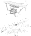
- FIG. 1 shows a three-dimensional view of a steering wheel assembly according to an embodiment of the present invention.
- FIG. 2 shows an exploded view of the steering wheel assembly according to the embodiment of the present invention. The steering wheel assembly according to the embodiment of the present invention will be described below with reference to FIGS. 1 and 2 .
- the steering wheel assembly 1 includes a steering wheel 10, a transmission member 20, and an electronic device 30.
- the steering wheel 10 includes a steering wheel rim 11 and a steering wheel center portion 12, and the steering wheel rim 11 is arranged around the steering wheel center portion 12.
- the steering wheel 10 further includes a plurality of radial members extending substantially in a radial direction thereof to connect the steering wheel rim 11 and the steering wheel center portion 12. It can be observed from FIG. 2 that two radial members are shown in the present embodiment. Of course, this is only an example, and the steering wheel assembly of the present invention may be provided with other numbers of radial members according to practical requirements.
- the transmission member 20 is configured to transmit torque between the steering wheel 10 and a steering column (not shown), for example, between the steering wheel center portion 12 of the steering wheel 10 and the steering column, thereby transmitting torque applied to the steering wheel 10 by a driver to the steering column to perform a steering operation of a vehicle.
- the transmission member 20 shown in FIG. 2 includes a flange. A bolt on a bracket 21 passes through the flange and fixes the two together by means of a nut 300, and thereafter, they will be fixed at a predetermined position on the vehicle.
- the steering wheel assembly 1 of the present invention further includes an electrical element 14.
- the electrical element 14 is configured to be in an annular shape to adapt to the shape of an annular portion of the steering wheel frame 13, thereby quickly covering the annular portion and being provided at the steering wheel rim 12 accordingly.
- the electrical element 14 provided at the steering wheel rim 12 will rotate together with the steering wheel 10 when the steering wheel 10 is rotated.
- the electronic device 30 is provided at the steering wheel center portion 12. In the steering wheel assembly 1 of the present invention, the electronic device 30 is provided to remain stationary when the steering wheel 10 is rotated.
- the electronic device 30 is provided at the steering wheel center portion 12 while always remaining as components separated from each other in terms of movement with respect to the steering wheel, thereby ensuring that the electronic device 30 is not affected by the rotation of the steering wheel, which will be described in more detail below.
- a clock spring unit 40 included in the steering wheel assembly 1 of the present invention is further shown.
- the clock spring unit 40 is provided below the electronic device 30.
- the electronic device 30 and the clock spring unit 40 are stacked one on top of the other in an axial direction of the steering wheel 10.
- the clock spring unit 40 may be located between the electronic device 30 and the transmission member 20 to separately provide signal transmission between the electrical element 14 and the vehicle, and between the electronic device 30 and the vehicle.
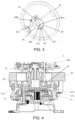
- FIG. 3 shows a schematic view of the clock spring unit in the steering wheel assembly according to the embodiment of the present invention.
- FIG. 4 shows a cross-sectional view of the steering wheel assembly according to the embodiment of the present invention.
- An exemplary clock spring unit 40 will be described in detail below with reference to FIGS. 2 , 3, and 4 .
- the clock spring unit 40 includes a first frame 41 for mounting a clock spring.
- the first frame 41 is in a substantially conical shape, and is fixed to the bracket 21 (which always remains stationary and is fixed to the flange of the transmission member 20 by a nut 300) of the transmission member 20 by means of a bolt 400.
- the first frame 41 includes a base 411 and a columnar portion 412 protruding from the base 411. As shown in FIG.
- the clock spring unit 40 includes a first connection terminal 40A connected to the electronic device 30, a second connection terminal 40B connected to the electrical element 14, and a third connection terminal 40C connected to the vehicle, wherein the first connection terminal 40A passes through a through-hole from a front surface of the clock spring unit 40 shown in FIG. 3 to a rear surface of the clock spring unit 40, and thus, it is only partially visible.
- the clock spring unit 40 includes an inner clock spring part 42 and an outer clock spring part 43 surrounding the inner clock spring part. The two clock spring parts are allowed to rotate relative to each other, and specifically, the outer clock spring part is able to rotate relative to the inner clock spring part.
- the inner clock spring part 42 is provided with the above-mentioned through-hole for the columnar portion to pass through, and the first connection terminal 40A passing through the through-hole.
- the third connection terminal 40C is also provided on the inner clock spring part 42 in the present embodiment.
- this is merely exemplary, and a plurality of third connection terminals may be provided.
- a dedicated third connection terminal is provided for each first connection terminal and each connection terminal.
- the outer clock spring part 43 is provided with the second connection terminal 40B.
- two second connection terminals 40B are provided on the outer clock spring part 43. The two are shown on the outer clock spring part 43 in FIG. 3 in a left-right arrangement.
- the electrical element 14 includes a first electrical element for hands-off detection and a second electrical element for steering wheel heating, and correspondingly, the two second connection terminals 40B are used for signal transmission for both functions of hands-off detection and steering wheel heating, respectively.
- the electrical element may also include other types of elements such as heart rate detection, vibration motors, lighting, buttons, etc.
- the outer clock spring part 43 is provided so as to rotate together with the steering wheel 10 when the steering wheel 10 is rotated
- the inner clock spring part 42 is provided so as to be fixed together with the first frame 41 and thus remain stationary when the steering wheel 10 is rotated.
- the through-hole as described above on the inner clock spring part 42 serves as a receiving portion for the columnar portion 412 of the first frame 41 to pass through so that at least a part thereof is thereafter received therein.
- the inner clock spring part 42 includes a first side surface 42A (i.e., a front surface shown in FIG. 3 ) facing the base 411.
- Positioning portions 421 (shown as two in number) and fixing portions 422 (shown as four in number) are provided on the first side surface 42A.
- the positioning portions 421 are used for positioning the inner clock spring part 42 relative to the base 411, and the fixing portions 422 are used for fixing the inner clock spring part 42 to the base 411.
- the base 411 of the first frame 41 is provided with a mating positioning portion that mates with the positioning portion 421.
- the positioning portion 421 is configured as a positioning pin
- the mating positioning portion is provided as a positioning hole that mates with the positioning pin.
- the fixing portion 422 protrudes from the first side surface 42A of the inner clock spring part 42 and is configured as a threaded hole.
- the threaded hole mates with a bolt 422 to fix the inner clock spring part 42 to the first frame 41, and is provided in a protruding portion that protrudes from the first side surface 42A.
- the steering wheel assembly of the present invention is not limited to the above-described example.
- the positioning portion is configured as a positioning hole
- the mating positioning portion 413 is provided as a positioning pin
- the positioning portion 421 is configured as a positioning pin
- the mating positioning portion is provided as a positioning hole
- the fixing portion 422 is recessed relative to the first side surface of the inner clock spring part and configured as a threaded hole.
- a torque transmission portion is provided between the steering wheel frame 13 and the outer clock spring part 43 for transmitting torque therebetween.
- the torque transmission portion includes a torque transmission hole 431 and a torque transmission pin inserted into the torque transmission hole 431.
- the torque transmission pin is provided on the steering wheel frame 13, and the torque transmission hole 431 is provided on the outer clock spring part 43.
- FIGS. 5(a), 5(b), and 5(c) show alternative embodiments.
- an alternative torque transmission pin 432 is provided on the outer clock spring part 43
- an alternative torque transmission hole 132 is provided on the steering wheel frame 13.
- another alternative torque transmission pin 433 is provided on the outer clock spring part 43, and has an expanded end capable of preventing the outer clock spring part 42 from moving in an upward direction to disengage from the steering wheel frame 13, and another alternative torque transmission hole 133 is provided on the steering wheel frame 13.
- a further alternative torque transmission pin 434 is provided on the outer clock spring part 43, and the torque transmission portion further includes a groove 134 that mates with the further alternative torque transmission pin 434 described above, the groove being provided at an outer edge of the steering wheel frame 13.
- any structure capable of transmitting torque may be used in the outer clock spring part and/or the steering wheel frame of the present invention.
- a rubber sleeve 4311 is further provided between the torque transmission hole and the torque transmission pin, which can reduce noise during torque transmission and wear of the steering wheel frame and the outer clock spring part, as shown in FIG. 4 .
- the electronic device 30 is configured as a display device and is fixed on the first frame 41 by means of a bolt 500, so that the display device remains stationary during the rotation of the steering wheel.
- the electronic device 30 includes a mounting plate 32.
- the mounting plate 32 is fixed to the first frame 41 by means of the bolt 500, which is shown in FIG. 4 .
- a columnar portion 412 of the first frame 41 is of a hollow structure and provided with a threaded hole on an inner surface thereof to mate with the bolt 500.
- the electronic device 30 further includes a display, and a hook portion is provided on a bottom side of the display, the hook portion passing from an upper side of the mounting plate 32 and being fixed to a lower side of the mounting plate 32 by means of a spring 33.
- a vibration reduction unit 50 is provided between the display and the mounting plate 32 to reduce vibrations around the display during use, thereby protecting the display.
- the vibration reduction unit 50 includes a vibration reduction body 51 provided between the display and the mounting plate 32, and the vibration reduction body 51 is provided with a vibration reduction portion 52 which is softer than the vibration reduction body 51.
- the vibration reduction portion 52 is detachably mounted to the vibration reduction body 51 as a separate part with respect to the vibration reduction body 51, and a plurality of vibration reduction portions 52 may be provided at a plurality of different positions of the vibration reduction body 51 according to space or other special requirements.
- the vibration reduction body 51 is further provided with a first stopper portion 53 for limiting the moving distance of the display relative to the mounting plate 32.
- a second stopper portion 31 for limiting the moving distance of the display relative to the mounting plate 32 is provided on the bottom side of the display, and is aligned with the vibration reduction portion 52 in the axial direction of the steering wheel 11 to simultaneously serve as a pre-positioning portion to position the display relative to the mounting plate.
- a fixing pin 100 is provided, a fixing hole is provided on the mounting plate, and the fixing pin 100 can pass through the fixing hole and a hole of the steering wheel center portion to fix the position of the clock spring unit in the circumferential direction with respect to the steering wheel before the steering wheel assembly is mounted to a vehicle (for example, during transportation).
- the clock spring unit is provided as an inner clock spring part and an outer clock spring part surrounding the inner clock spring part; the inner clock spring part remains stationary when the steering wheel is rotated, and the outer clock spring part is rotated together with the steering wheel when the steering wheel is rotated; and the two spring parts are respectively provided with connection terminals for the needs of signal transmission at different positions of the steering wheel. Therefore, the above arrangement in particular allows the electronic device at the steering wheel center portion to remain stationary when the steering wheel is rotated, while allowing the electrical element at the steering wheel rim to rotate with the steering wheel when the steering wheel is rotated.
- the steering wheel assembly of the present invention is particularly beneficial when the electronic device is a display device (including, but not limited thereto.
- the steering wheel assembly of the present invention can support a plurality of functions to be equipped on the steering wheel.
Landscapes
- Engineering & Computer Science (AREA)
- Mechanical Engineering (AREA)
- Chemical & Material Sciences (AREA)
- Combustion & Propulsion (AREA)
- Transportation (AREA)
- Steering Controls (AREA)
Abstract
Description
- The present invention relates to accessories for vehicles, and relates in particular to a steering wheel assembly.
- With the development of the vehicle industry, as an important component in a steering system, a steering wheel is not only used for a steering function, but is also expected to have additional functions. For example, it is desired that a vehicle steering wheel is able to generate heat to provide a more comfortable driving experience when a driving operation is performed in a cold environment. For another example, in order to improve safety, a hands-off detection function is provided on the steering wheel to detect whether a driver is in a hands-off state and to issue a warning when it is detected that the driver is in the hands-off state. In addition, various other functions such as audio control, cruise control, Bluetooth connection, a trip computer, and the like may be provided on the steering wheel, and these other functions may be presented to the driver by a display device located at the center of the steering wheel. Each of the above functions requires signal transmission between a corresponding component mounted on the steering wheel and the vehicle.
- Current steering wheels rotate with a steering column as an assembly on the steering column. Such a steering wheel-steering column configuration does not allow various components (e.g., the display device) mounted on the steering wheel to remain stationary with respect to the vehicle during rotation of the steering wheel, which is disadvantageous for components that are required to remain stationary at all times without rotation (for example, rotation will result in an inability to operate the functions), thereby not supporting a plurality of functions to be equipped on the steering wheel.
- Therefore, it is desired to provide a steering wheel that supports a plurality of functions to be equipped on the steering wheel.
- It is an object of the present invention to provide a steering wheel assembly which supports a plurality of functions to be equipped on a steering wheel. In particular, the steering wheel assembly of the present invention can support a plurality of functions (e.g., audio control, cruise control, Bluetooth connection, trip computer, multimedia, etc.) integrated on the display device at the center of the steering wheel, which is achieved by keeping the display device stationary relative to the vehicle during rotation of the steering wheel.
- The present invention provides a steering wheel assembly, comprising a steering wheel, a transmission member, and an electronic device,
wherein, - the transmission member is configured to transmit torque between the steering wheel and a steering column;
- the steering wheel comprises a steering wheel center portion and a steering wheel rim surrounding the steering wheel center portion, the steering wheel rim is provided with an electrical element, and the electronic device is provided at the steering wheel center portion and remains stationary when the steering wheel is rotated; and
- a clock spring unit is provided below the electronic device, and comprises a first connection terminal connected to the electronic device, a second connection terminal connected to the electrical element, and a third connection terminal connected to a vehicle, and
- wherein the clock spring unit comprises an inner clock spring part and an outer clock spring part surrounding the inner clock spring part, the inner clock spring part is provided with the first connection terminal and remains stationary when the steering wheel is rotated, and the outer clock spring part is provided with the second connection terminal and rotates together with the steering wheel when the steering wheel is rotated.
- According to an embodiment of the present invention, the clock spring unit is located between the electronic device and the transmission member in an axial direction of the steering wheel, and comprises a first frame for mounting the inner clock spring part, and the first frame is fixed to a stationary part of the transmission member.
- According to an embodiment of the present invention, the first frame comprises a base and a columnar portion protruding from the base, and the inner clock spring part is provided with a receiving portion for the columnar portion to pass through, and is fixed to the base.
- According to an embodiment of the present invention, the inner clock spring part comprises a first side surface facing the base, and the first side surface is provided with a positioning portion for positioning relative to the base and a fixing portion for fixing to the base.
- According to an embodiment of the present invention, the base is provided with a mating positioning portion that mates with the positioning portion, one of the positioning portion and the mating positioning portion is provided as a positioning pin, and the other is provided as a positioning hole; and/or,
the fixing portion is configured as a threaded hole. - According to an embodiment of the present invention, a torque transmission portion is provided between a steering wheel frame of the steering wheel and the outer clock spring part for transmitting torque therebetween.
- According to an embodiment of the present invention, the torque transmission portion comprises a torque transmission hole and a torque transmission pin inserted into the torque transmission hole, the torque transmission pin being provided on one of the steering wheel frame and the outer clock spring part and the torque transmission hole being provided on the other.
- According to an embodiment of the present invention, the electronic device is fixed to the first frame and configured as a display device.
- According to an embodiment of the present invention, the electronic device comprises a mounting plate fixed to the first frame and a display, and a vibration reduction unit is provided between the display and the mounting plate.
- According to an embodiment of the present invention, a hook portion is provided on a bottom side of the display, the hook portion passing from an upper side of the mounting plate and being fixed to a lower side of the mounting plate by means of a spring.
- According to an embodiment of the present invention, the vibration reduction unit comprises a vibration reduction body provided between the display and the mounting plate, and the vibration reduction body is provided with a vibration reduction portion that is softer than the vibration reduction body.
- According to an embodiment of the present invention, the vibration reduction body is further provided with a first stopper portion for limiting a moving distance of the display relative to the mounting plate.
- According to an embodiment of the present invention, the mounting plate is provided with a fixing hole, and a fixing pin can pass through the fixing hole and a hole of the steering wheel center portion to fix a position of the clock spring unit in a circumferential direction relative to the steering wheel before the steering wheel assembly is mounted on a vehicle; and/or,
a second stopper portion for limiting the moving distance of the display relative to the mounting plate is provided on the bottom side of the display, and is aligned with the vibration reduction portion in the axial direction of the steering wheel. - According to an embodiment of the present invention, a rubber sleeve is further provided between the torque transmission hole and the torque transmission pin.
- According to an embodiment of the invention, the electrical element comprises a first electrical element for hands-off detection and/or a second electrical element for steering wheel heating.
- According to an embodiment of the present invention, the third connection terminal is provided on the inner clock spring part.
- The features, advantages, and technical effects of exemplary embodiments of the present invention will be described below with reference to the accompanying drawings. In the accompanying drawings, the same reference numbers denote the same elements, where
-
FIG. 1 shows a three-dimensional view of a steering wheel assembly according to an embodiment of the present invention. -
FIG. 2 shows an exploded view of the steering wheel assembly according to the embodiment of the present invention. -
FIG. 3 shows a schematic view of a clock spring unit in the steering wheel assembly according to the embodiment of the present invention. -
FIG. 4 shows a cross-sectional view of the steering wheel assembly according to the embodiment of the present invention. -
FIGS. 5(a), 5(b), and 5(c) show partial cross-sectional views of a steering wheel assembly according to another embodiment of the present invention. -
FIGS. 6(a) and 6(b) show partial cross-sectional views of a steering wheel assembly according to another embodiment of the present invention. - Specific embodiments of a steering wheel assembly according to the present invention will be described below with reference to the accompanying drawings. The following detailed description and the accompanying drawings are used to illustratively explain the principles of the present invention. The present invention is not limited to the described preferred embodiments, and various embodiments described in the present invention can be used individually or in any combination. The scope of protection of the present invention is defined by the claims.
- In addition, terms for spatial relations (such as "upper", "lower", "left", "right", etc.) are used to describe a relative positional relationship between an element and another element shown in the accompanying drawings. Therefore, when used, the terms for spatial relations may be applied to directions different from those shown in the accompanying drawings. Obviously, although all of these terms for spatial relations refer to the directions shown in the accompanying drawings for ease of explanation, a person skilled in the art will appreciate that directions different from those shown in the drawings may be used.
-
FIG. 1 shows a three-dimensional view of a steering wheel assembly according to an embodiment of the present invention.FIG. 2 shows an exploded view of the steering wheel assembly according to the embodiment of the present invention. The steering wheel assembly according to the embodiment of the present invention will be described below with reference toFIGS. 1 and 2 . - As shown in
FIGS. 1 and 2 , thesteering wheel assembly 1 provided by the present invention includes asteering wheel 10, atransmission member 20, and anelectronic device 30. Thesteering wheel 10 includes a steering wheel rim 11 and a steering wheel center portion 12, and the steering wheel rim 11 is arranged around the steering wheel center portion 12. Generally, thesteering wheel 10 further includes a plurality of radial members extending substantially in a radial direction thereof to connect the steering wheel rim 11 and the steering wheel center portion 12. It can be observed fromFIG. 2 that two radial members are shown in the present embodiment. Of course, this is only an example, and the steering wheel assembly of the present invention may be provided with other numbers of radial members according to practical requirements. - The
transmission member 20 is configured to transmit torque between thesteering wheel 10 and a steering column (not shown), for example, between the steering wheel center portion 12 of thesteering wheel 10 and the steering column, thereby transmitting torque applied to thesteering wheel 10 by a driver to the steering column to perform a steering operation of a vehicle. Thetransmission member 20 shown inFIG. 2 includes a flange. A bolt on abracket 21 passes through the flange and fixes the two together by means of anut 300, and thereafter, they will be fixed at a predetermined position on the vehicle. - Furthermore, as shown in
FIG. 2 , thesteering wheel assembly 1 of the present invention further includes anelectrical element 14. In an embodiment, theelectrical element 14 is configured to be in an annular shape to adapt to the shape of an annular portion of thesteering wheel frame 13, thereby quickly covering the annular portion and being provided at the steering wheel rim 12 accordingly. Of course, theelectrical element 14 provided at the steering wheel rim 12 will rotate together with thesteering wheel 10 when thesteering wheel 10 is rotated. Theelectronic device 30 is provided at the steering wheel center portion 12. In thesteering wheel assembly 1 of the present invention, theelectronic device 30 is provided to remain stationary when thesteering wheel 10 is rotated. This means that theelectronic device 30 is provided at the steering wheel center portion 12 while always remaining as components separated from each other in terms of movement with respect to the steering wheel, thereby ensuring that theelectronic device 30 is not affected by the rotation of the steering wheel, which will be described in more detail below. - Also, in
FIG. 2 , aclock spring unit 40 included in thesteering wheel assembly 1 of the present invention is further shown. Theclock spring unit 40 is provided below theelectronic device 30. In other words, theelectronic device 30 and theclock spring unit 40 are stacked one on top of the other in an axial direction of thesteering wheel 10. For example, theclock spring unit 40 may be located between theelectronic device 30 and thetransmission member 20 to separately provide signal transmission between theelectrical element 14 and the vehicle, and between theelectronic device 30 and the vehicle. -
FIG. 3 shows a schematic view of the clock spring unit in the steering wheel assembly according to the embodiment of the present invention.FIG. 4 shows a cross-sectional view of the steering wheel assembly according to the embodiment of the present invention. An exemplaryclock spring unit 40 will be described in detail below with reference toFIGS. 2 ,3, and 4 . - As shown in
FIG. 2 , theclock spring unit 40 includes afirst frame 41 for mounting a clock spring. Thefirst frame 41 is in a substantially conical shape, and is fixed to the bracket 21 (which always remains stationary and is fixed to the flange of thetransmission member 20 by a nut 300) of thetransmission member 20 by means of abolt 400. Moreover, specifically, thefirst frame 41 includes abase 411 and acolumnar portion 412 protruding from thebase 411. As shown inFIG. 3 , theclock spring unit 40 includes afirst connection terminal 40A connected to theelectronic device 30, asecond connection terminal 40B connected to theelectrical element 14, and athird connection terminal 40C connected to the vehicle, wherein thefirst connection terminal 40A passes through a through-hole from a front surface of theclock spring unit 40 shown inFIG. 3 to a rear surface of theclock spring unit 40, and thus, it is only partially visible. Furthermore, theclock spring unit 40 includes an innerclock spring part 42 and an outerclock spring part 43 surrounding the inner clock spring part. The two clock spring parts are allowed to rotate relative to each other, and specifically, the outer clock spring part is able to rotate relative to the inner clock spring part. The innerclock spring part 42 is provided with the above-mentioned through-hole for the columnar portion to pass through, and thefirst connection terminal 40A passing through the through-hole. Thethird connection terminal 40C is also provided on the innerclock spring part 42 in the present embodiment. Of course, this is merely exemplary, and a plurality of third connection terminals may be provided. For example, a dedicated third connection terminal is provided for each first connection terminal and each connection terminal. In the meantime, the outerclock spring part 43 is provided with thesecond connection terminal 40B. In the present embodiment, twosecond connection terminals 40B are provided on the outerclock spring part 43. The two are shown on the outerclock spring part 43 inFIG. 3 in a left-right arrangement. For example, theelectrical element 14 includes a first electrical element for hands-off detection and a second electrical element for steering wheel heating, and correspondingly, the twosecond connection terminals 40B are used for signal transmission for both functions of hands-off detection and steering wheel heating, respectively. Of course, this is merely an example, and the electrical element may also include other types of elements such as heart rate detection, vibration motors, lighting, buttons, etc. - In the present invention, the outer
clock spring part 43 is provided so as to rotate together with thesteering wheel 10 when thesteering wheel 10 is rotated, and the innerclock spring part 42 is provided so as to be fixed together with thefirst frame 41 and thus remain stationary when thesteering wheel 10 is rotated. - The fixing of the inner clock spring part and the outer clock spring part will be separately described below.
- The through-hole as described above on the inner
clock spring part 42 serves as a receiving portion for thecolumnar portion 412 of thefirst frame 41 to pass through so that at least a part thereof is thereafter received therein. Furthermore, the innerclock spring part 42 includes afirst side surface 42A (i.e., a front surface shown inFIG. 3 ) facing thebase 411. Positioning portions 421 (shown as two in number) and fixing portions 422 (shown as four in number) are provided on thefirst side surface 42A. The positioningportions 421 are used for positioning the innerclock spring part 42 relative to thebase 411, and the fixingportions 422 are used for fixing the innerclock spring part 42 to thebase 411. It can be understood that, except the through-hole for receiving the first frame, located at the center position, no through-hole can be provided at other positions of the clock spring unit due to wire harness contained therein, and therefore, the above-mentioned fixing structure in combination with the positioning structure will facilitate easy fixing of the inner clock spring part. - In an example, as shown in
FIGS. 3 and 4 , thebase 411 of thefirst frame 41 is provided with a mating positioning portion that mates with thepositioning portion 421. Moreover, thepositioning portion 421 is configured as a positioning pin, and the mating positioning portion is provided as a positioning hole that mates with the positioning pin. The fixingportion 422 protrudes from thefirst side surface 42A of the innerclock spring part 42 and is configured as a threaded hole. The threaded hole mates with abolt 422 to fix the innerclock spring part 42 to thefirst frame 41, and is provided in a protruding portion that protrudes from thefirst side surface 42A. Of course, the steering wheel assembly of the present invention is not limited to the above-described example. For example,FIGS. 6(a) and 6(b) show alternative embodiments. InFIG. 6(a) , the positioning portion is configured as a positioning hole, and themating positioning portion 413 is provided as a positioning pin. InFIG. 6(b) , thepositioning portion 421 is configured as a positioning pin, the mating positioning portion is provided as a positioning hole, and the fixingportion 422 is recessed relative to the first side surface of the inner clock spring part and configured as a threaded hole. - In an example, as shown in
FIGS. 3 and 4 , a torque transmission portion is provided between thesteering wheel frame 13 and the outerclock spring part 43 for transmitting torque therebetween. Specifically, the torque transmission portion includes atorque transmission hole 431 and a torque transmission pin inserted into thetorque transmission hole 431. The torque transmission pin is provided on thesteering wheel frame 13, and thetorque transmission hole 431 is provided on the outerclock spring part 43. Of course, the steering wheel assembly of the present invention is not limited to the above-described example. For example,FIGS. 5(a), 5(b), and 5(c) show alternative embodiments. InFIG. 5(a) , an alternativetorque transmission pin 432 is provided on the outerclock spring part 43, and an alternativetorque transmission hole 132 is provided on thesteering wheel frame 13. InFIG. 5(b) , another alternativetorque transmission pin 433 is provided on the outerclock spring part 43, and has an expanded end capable of preventing the outerclock spring part 42 from moving in an upward direction to disengage from thesteering wheel frame 13, and another alternativetorque transmission hole 133 is provided on thesteering wheel frame 13. InFIG. 5(c) , a further alternativetorque transmission pin 434 is provided on the outerclock spring part 43, and the torque transmission portion further includes agroove 134 that mates with the further alternativetorque transmission pin 434 described above, the groove being provided at an outer edge of thesteering wheel frame 13. Of course, any structure capable of transmitting torque may be used in the outer clock spring part and/or the steering wheel frame of the present invention. - As an embodiment of the present invention, a
rubber sleeve 4311 is further provided between the torque transmission hole and the torque transmission pin, which can reduce noise during torque transmission and wear of the steering wheel frame and the outer clock spring part, as shown inFIG. 4 . - The steering wheel assembly according to the embodiment of the present invention will be further described below with reference to
FIGS. 1 and 2 . - As an example, the
electronic device 30 is configured as a display device and is fixed on thefirst frame 41 by means of abolt 500, so that the display device remains stationary during the rotation of the steering wheel. Specifically, theelectronic device 30 includes a mounting plate 32. The mounting plate 32 is fixed to thefirst frame 41 by means of thebolt 500, which is shown inFIG. 4 . Acolumnar portion 412 of thefirst frame 41 is of a hollow structure and provided with a threaded hole on an inner surface thereof to mate with thebolt 500. Theelectronic device 30 further includes a display, and a hook portion is provided on a bottom side of the display, the hook portion passing from an upper side of the mounting plate 32 and being fixed to a lower side of the mounting plate 32 by means of a spring 33. - Further, a
vibration reduction unit 50 is provided between the display and the mounting plate 32 to reduce vibrations around the display during use, thereby protecting the display. In the present embodiment, thevibration reduction unit 50 includes avibration reduction body 51 provided between the display and the mounting plate 32, and thevibration reduction body 51 is provided with a vibration reduction portion 52 which is softer than thevibration reduction body 51. The vibration reduction portion 52 is detachably mounted to thevibration reduction body 51 as a separate part with respect to thevibration reduction body 51, and a plurality of vibration reduction portions 52 may be provided at a plurality of different positions of thevibration reduction body 51 according to space or other special requirements. Thevibration reduction body 51 is further provided with afirst stopper portion 53 for limiting the moving distance of the display relative to the mounting plate 32. Correspondingly, asecond stopper portion 31 for limiting the moving distance of the display relative to the mounting plate 32 is provided on the bottom side of the display, and is aligned with the vibration reduction portion 52 in the axial direction of the steering wheel 11 to simultaneously serve as a pre-positioning portion to position the display relative to the mounting plate. - As an example, as shown in
FIGS. 1 and 2 , a fixing pin 100 is provided, a fixing hole is provided on the mounting plate, and the fixing pin 100 can pass through the fixing hole and a hole of the steering wheel center portion to fix the position of the clock spring unit in the circumferential direction with respect to the steering wheel before the steering wheel assembly is mounted to a vehicle (for example, during transportation). - It should be noted that, in the steering wheel assembly of the present invention, the clock spring unit is provided as an inner clock spring part and an outer clock spring part surrounding the inner clock spring part; the inner clock spring part remains stationary when the steering wheel is rotated, and the outer clock spring part is rotated together with the steering wheel when the steering wheel is rotated; and the two spring parts are respectively provided with connection terminals for the needs of signal transmission at different positions of the steering wheel. Therefore, the above arrangement in particular allows the electronic device at the steering wheel center portion to remain stationary when the steering wheel is rotated, while allowing the electrical element at the steering wheel rim to rotate with the steering wheel when the steering wheel is rotated. The steering wheel assembly of the present invention is particularly beneficial when the electronic device is a display device (including, but not limited thereto. It may also be other electronic devices that are similarly not desirable to rotate with the steering wheel), as the display device needs to provide a plurality of functions while being always stationary relative to the vehicle without rotating. Therefore, the steering wheel assembly of the present invention can support a plurality of functions to be equipped on the steering wheel.
- As described above, although the exemplary embodiments of the present invention have been described with reference to the accompanying drawings in the description, the present invention is not limited to the aforementioned specific embodiments, and the scope of protection of the present invention should be defined by the claims and equivalent meanings thereof.
Claims (16)
- A steering wheel assembly (1), comprising a steering wheel (10), a transmission member (20), and an electronic device (30),
characterized in that:the transmission member (20) is configured to transmit torque between the steering wheel (10) and a steering column;the steering wheel (10) comprises a steering wheel center portion (12) and a steering wheel rim (11) surrounding the steering wheel center portion, the steering wheel rim (11) is provided with an electrical element (14), and the electronic device (30) is provided at the steering wheel center portion (12) and remains stationary when the steering wheel (10) is rotated; anda clock spring unit (40) is provided below the electronic device (30), and comprises a first connection terminal (40A) connected to the electronic device (30), a second connection terminal (40B) connected to the electrical element (14), and a third connection terminal (40C) connected to a vehicle,wherein the clock spring unit (40) comprises an inner clock spring part (42) and an outer clock spring part (43) surrounding the inner clock spring part, the inner clock spring part (42) is provided with the first connection terminal (40A) and remains stationary when the steering wheel (10) is rotated, and the outer clock spring part (43) is provided with the second connection terminal (40B) and rotates together with the steering wheel (10) when the steering wheel (10) is rotated. - The steering wheel assembly (1) according to claim 1, wherein, the clock spring unit (40) is located between the electronic device (30) and the transmission member (20) in an axial direction of the steering wheel (10), and comprises a first frame (41) for mounting the inner clock spring part (42), and the first frame (41) is fixed to a stationary part of the transmission member (20).
- The steering wheel assembly (1) according to claim 2, wherein, the first frame (41) comprises a base (411) and a columnar portion (412) protruding from the base (411), and the inner clock spring part (42) is provided with a receiving portion for the columnar portion (412) to pass through, and is fixed to the base (411).
- The steering wheel assembly (1) according to claim 3, wherein, the inner clock spring part (42) comprises a first side surface (42A) facing the base (411), and the first side surface (42A) is provided with a positioning portion (421) for positioning relative to the base (411) and a fixing portion (422) for fixing to the base (411).
- The steering wheel assembly (1) according to claim 4, wherein, the base (411) is provided with a mating positioning portion that mates with the positioning portion (421), one of the positioning portion (421) and the mating positioning portion is provided as a positioning pin, and the other is provided as a positioning hole; and/or,
the fixing portion (422) is configured as a threaded hole. - The steering wheel assembly (1) according to claim 1, wherein, a torque transmission portion is provided between a steering wheel frame (13) of the steering wheel (10) and the outer clock spring part (43) for transmitting torque therebetween.
- The steering wheel assembly (1) according to claim 6, wherein, the torque transmission portion comprises a torque transmission hole (431) and a torque transmission pin inserted into the torque transmission hole (431), the torque transmission pin being provided on one of the steering wheel frame (13) and the outer clock spring part (43) and the torque transmission hole being provided on the other.
- The steering wheel assembly (1) according to claim 2, wherein, the electronic device (30) is fixed to the first frame (41) and is configured as a display device.
- The steering wheel assembly (1) according to claim 8, wherein, the electronic device (30) comprises a mounting plate (32) fixed to the first frame (41) and a display, and a vibration reduction unit (50) is provided between the display and the mounting plate (32).
- The steering wheel assembly (1) according to claim 9, wherein, a hook portion is provided on a bottom side of the display, the hook portion passing from an upper side of the mounting plate (32) and being fixed to a lower side of the mounting plate (32) by means of a spring (33).
- The steering wheel assembly (1) according to claim 10, wherein, the vibration reduction unit (50) comprises a vibration reduction body (51) provided between the display and the mounting plate (32), and the vibration reduction body (51) is provided with a vibration reduction portion (52) that is softer than the vibration reduction body (51).
- The steering wheel assembly (1) according to claim 11, wherein, the vibration reduction body (51) is further provided with a first stopper portion (53) for limiting a moving distance of the display relative to the mounting plate (32).
- The steering wheel assembly (1) according to claim 12, wherein, the mounting plate (32) is provided with a fixing hole, and a fixing pin (100) can pass through the fixing hole and a hole of the steering wheel center portion (12) to fix a position of the clock spring unit (40) in a circumferential direction relative to the steering wheel (10) before the steering wheel assembly (1) is mounted on a vehicle; and/or,
a second stopper portion (31) for limiting a moving distance of the display relative to the mounting plate (32) is provided on the bottom side of the display, and is aligned with the vibration reduction portion (52) in the axial direction of the steering wheel (10). - The steering wheel assembly (1) according to claim 7, wherein, a rubber sleeve (4311) is further provided between the torque transmission hole (431) and the torque transmission pin.
- The steering wheel assembly (1) according to claim 1, wherein, the electrical element (14) comprises a first electrical element for hands-off detection and/or a second electrical element for steering wheel heating.
- The steering wheel assembly (1) according to claim 1, wherein, the third connection terminal (40C) is provided on the inner clock spring part (42).
Applications Claiming Priority (2)
| Application Number | Priority Date | Filing Date | Title |
|---|---|---|---|
| CN202210466334.2A CN117002600A (en) | 2022-04-29 | 2022-04-29 | Steering wheel assembly |
| PCT/CN2023/086887 WO2023207552A1 (en) | 2022-04-29 | 2023-04-07 | Steering wheel assembly |
Publications (2)
| Publication Number | Publication Date |
|---|---|
| EP4516595A1 true EP4516595A1 (en) | 2025-03-05 |
| EP4516595A4 EP4516595A4 (en) | 2026-04-01 |
Family
ID=88517456
Family Applications (1)
| Application Number | Title | Priority Date | Filing Date |
|---|---|---|---|
| EP23794985.4A Pending EP4516595A4 (en) | 2022-04-29 | 2023-04-07 | STEERING WHEEL SETUP |
Country Status (4)
| Country | Link |
|---|---|
| US (1) | US12420854B1 (en) |
| EP (1) | EP4516595A4 (en) |
| CN (1) | CN117002600A (en) |
| WO (1) | WO2023207552A1 (en) |
Family Cites Families (13)
| Publication number | Priority date | Publication date | Assignee | Title |
|---|---|---|---|---|
| JPS5993950U (en) * | 1983-02-25 | 1984-06-26 | 豊田合成株式会社 | Steering wheel cable storage structure |
| DE10214607A1 (en) * | 2002-04-03 | 2003-10-16 | Tyco Electronics Amp Gmbh | Steering wheel unit for vehicle steering system has controller on steering wheel side mounted in or on steering wheel side housing part of clock spring unit, which is attached to steering shaft |
| US7290789B2 (en) * | 2003-07-22 | 2007-11-06 | Trw Automotive Safety Systems Gmbh | Vehicle steering device with stationary central part |
| DE102004048837A1 (en) * | 2004-03-01 | 2005-09-29 | Takata-Petri Ag | Device for mounting module on motor vehicle steering wheel has electrical connection arrangement for connecting first and second electrical contact units in separate sub-assemblies |
| DE102005053183A1 (en) * | 2005-11-03 | 2007-05-10 | Valeo Schalter Und Sensoren Gmbh | Assembly for a steering system of a motor vehicle |
| EP2987682B1 (en) * | 2014-08-20 | 2020-12-16 | Nexans | Assembly for electrical wires installed in a motor vehicle |
| US9533687B2 (en) | 2014-12-30 | 2017-01-03 | Tk Holdings Inc. | Occupant monitoring systems and methods |
| DE102016204105B4 (en) * | 2016-03-11 | 2023-07-06 | Joyson Safety Systems Germany Gmbh | Steering wheel for a motor vehicle |
| JP6834886B2 (en) * | 2017-09-28 | 2021-02-24 | 豊田合成株式会社 | Electrical connection device for steering |
| WO2019173750A1 (en) * | 2018-03-08 | 2019-09-12 | Joyson Safety Systems Acquisition Llc | Vehicle illumination systems and methods |
| CN108346384A (en) * | 2018-03-20 | 2018-07-31 | 马瑞利汽车电子(广州)有限公司 | A kind of mounting structure of automobile instrument LCD screen |
| WO2019232243A1 (en) * | 2018-05-30 | 2019-12-05 | Joyson Safety Systems Acquisition Llc | Integrated electronic control unit for a steering wheel assembly |
| CN112124217A (en) * | 2020-10-27 | 2020-12-25 | 嘉兴市乐裕机电设备有限公司 | Steering wheel with display screen |
-
2022
- 2022-04-29 CN CN202210466334.2A patent/CN117002600A/en active Pending
-
2023
- 2023-04-07 WO PCT/CN2023/086887 patent/WO2023207552A1/en not_active Ceased
- 2023-04-07 EP EP23794985.4A patent/EP4516595A4/en active Pending
- 2023-04-07 US US18/861,457 patent/US12420854B1/en active Active
Also Published As
| Publication number | Publication date |
|---|---|
| US20250296616A1 (en) | 2025-09-25 |
| CN117002600A (en) | 2023-11-07 |
| EP4516595A4 (en) | 2026-04-01 |
| US12420854B1 (en) | 2025-09-23 |
| WO2023207552A1 (en) | 2023-11-02 |
Similar Documents
| Publication | Publication Date | Title |
|---|---|---|
| CN107206948B (en) | cable retention structure | |
| EP3118083B1 (en) | Steering wheel | |
| US20200377139A1 (en) | Coupling device for the attachment of an airbag module to a vehicle steering wheel in an oscillatory manner | |
| EP0769440A2 (en) | Steering wheel mounting assembly | |
| US9126556B2 (en) | Air-bag module mounting structure | |
| KR102105379B1 (en) | Steering apparatus with irrotational core portion for vehicles | |
| JP2011141768A (en) | Vehicle operating pedal device | |
| US9868334B2 (en) | Installation structure for vehicle-mounted device | |
| US6773164B2 (en) | Vehicle wheel bearing and wheel-speed-sensor connector-plug bracket | |
| US12420854B1 (en) | Steering wheel assembly | |
| US10899301B2 (en) | Assembly of a driver airbag module and a steering wheel | |
| JP2813579B2 (en) | Automotive steering wheel attachment to steering shaft | |
| JP2011068192A (en) | Vehicle switch unit | |
| US20250351286A1 (en) | Vehicle control apparatus | |
| US7055406B1 (en) | Axle housing assembly | |
| JP2001310740A (en) | Switch unit for steering wheel in vehicle | |
| CN106314348B (en) | Driver seat airbag module | |
| CN219821547U (en) | Steering wheel assembly | |
| US12202425B2 (en) | Coupling device for securing an airbag module to a vehicle steering wheel | |
| CN214215481U (en) | Mounting structure and vehicle of well accuse car machine | |
| JP6253195B2 (en) | handle | |
| US5769450A (en) | Steering wheel assembly containing an air bag module | |
| JP4365714B2 (en) | Automotive electronics | |
| JP6253196B2 (en) | handle | |
| JP2003170837A (en) | Impact absorbing steering device |
Legal Events
| Date | Code | Title | Description |
|---|---|---|---|
| STAA | Information on the status of an ep patent application or granted ep patent |
Free format text: STATUS: THE INTERNATIONAL PUBLICATION HAS BEEN MADE |
|
| PUAI | Public reference made under article 153(3) epc to a published international application that has entered the european phase |
Free format text: ORIGINAL CODE: 0009012 |
|
| STAA | Information on the status of an ep patent application or granted ep patent |
Free format text: STATUS: REQUEST FOR EXAMINATION WAS MADE |
|
| 17P | Request for examination filed |
Effective date: 20241114 |
|
| AK | Designated contracting states |
Kind code of ref document: A1 Designated state(s): AL AT BE BG CH CY CZ DE DK EE ES FI FR GB GR HR HU IE IS IT LI LT LU LV MC ME MK MT NL NO PL PT RO RS SE SI SK SM TR |
|
| DAV | Request for validation of the european patent (deleted) | ||
| DAX | Request for extension of the european patent (deleted) | ||
| A4 | Supplementary search report drawn up and despatched |
Effective date: 20260302 |
|
| RIC1 | Information provided on ipc code assigned before grant |
Ipc: B60R 16/027 20060101AFI20260224BHEP Ipc: B60R 21/203 20060101ALI20260224BHEP Ipc: H02G 11/02 20060101ALI20260224BHEP Ipc: B62D 1/04 20060101ALI20260224BHEP Ipc: H01R 35/00 20060101ALI20260224BHEP Ipc: B60R 16/02 20060101ALI20260224BHEP Ipc: B60K 35/22 20240101ALI20260224BHEP Ipc: B62D 1/06 20060101ALI20260224BHEP Ipc: B60K 35/60 20240101ALI20260224BHEP Ipc: B62D 1/10 20060101ALI20260224BHEP |