EP4516593A1 - Display system and work vehicle - Google Patents
Display system and work vehicle Download PDFInfo
- Publication number
- EP4516593A1 EP4516593A1 EP23815835.6A EP23815835A EP4516593A1 EP 4516593 A1 EP4516593 A1 EP 4516593A1 EP 23815835 A EP23815835 A EP 23815835A EP 4516593 A1 EP4516593 A1 EP 4516593A1
- Authority
- EP
- European Patent Office
- Prior art keywords
- work vehicle
- screen
- vibration
- information
- controller
- Prior art date
- Legal status (The legal status is an assumption and is not a legal conclusion. Google has not performed a legal analysis and makes no representation as to the accuracy of the status listed.)
- Pending
Links
Images






Classifications
-
- B—PERFORMING OPERATIONS; TRANSPORTING
- B60—VEHICLES IN GENERAL
- B60K—ARRANGEMENT OR MOUNTING OF PROPULSION UNITS OR OF TRANSMISSIONS IN VEHICLES; ARRANGEMENT OR MOUNTING OF PLURAL DIVERSE PRIME-MOVERS IN VEHICLES; AUXILIARY DRIVES FOR VEHICLES; INSTRUMENTATION OR DASHBOARDS FOR VEHICLES; ARRANGEMENTS IN CONNECTION WITH COOLING, AIR INTAKE, GAS EXHAUST OR FUEL SUPPLY OF PROPULSION UNITS IN VEHICLES
- B60K35/00—Instruments specially adapted for vehicles; Arrangement of instruments in or on vehicles
- B60K35/10—Input arrangements, i.e. from user to vehicle, associated with vehicle functions or specially adapted therefor
-
- B—PERFORMING OPERATIONS; TRANSPORTING
- B60—VEHICLES IN GENERAL
- B60K—ARRANGEMENT OR MOUNTING OF PROPULSION UNITS OR OF TRANSMISSIONS IN VEHICLES; ARRANGEMENT OR MOUNTING OF PLURAL DIVERSE PRIME-MOVERS IN VEHICLES; AUXILIARY DRIVES FOR VEHICLES; INSTRUMENTATION OR DASHBOARDS FOR VEHICLES; ARRANGEMENTS IN CONNECTION WITH COOLING, AIR INTAKE, GAS EXHAUST OR FUEL SUPPLY OF PROPULSION UNITS IN VEHICLES
- B60K35/00—Instruments specially adapted for vehicles; Arrangement of instruments in or on vehicles
- B60K35/20—Output arrangements, i.e. from vehicle to user, associated with vehicle functions or specially adapted therefor
-
- B—PERFORMING OPERATIONS; TRANSPORTING
- B60—VEHICLES IN GENERAL
- B60K—ARRANGEMENT OR MOUNTING OF PROPULSION UNITS OR OF TRANSMISSIONS IN VEHICLES; ARRANGEMENT OR MOUNTING OF PLURAL DIVERSE PRIME-MOVERS IN VEHICLES; AUXILIARY DRIVES FOR VEHICLES; INSTRUMENTATION OR DASHBOARDS FOR VEHICLES; ARRANGEMENTS IN CONNECTION WITH COOLING, AIR INTAKE, GAS EXHAUST OR FUEL SUPPLY OF PROPULSION UNITS IN VEHICLES
- B60K35/00—Instruments specially adapted for vehicles; Arrangement of instruments in or on vehicles
- B60K35/20—Output arrangements, i.e. from vehicle to user, associated with vehicle functions or specially adapted therefor
- B60K35/21—Output arrangements, i.e. from vehicle to user, associated with vehicle functions or specially adapted therefor using visual output, e.g. blinking lights or matrix displays
- B60K35/22—Display screens
-
- B—PERFORMING OPERATIONS; TRANSPORTING
- B60—VEHICLES IN GENERAL
- B60K—ARRANGEMENT OR MOUNTING OF PROPULSION UNITS OR OF TRANSMISSIONS IN VEHICLES; ARRANGEMENT OR MOUNTING OF PLURAL DIVERSE PRIME-MOVERS IN VEHICLES; AUXILIARY DRIVES FOR VEHICLES; INSTRUMENTATION OR DASHBOARDS FOR VEHICLES; ARRANGEMENTS IN CONNECTION WITH COOLING, AIR INTAKE, GAS EXHAUST OR FUEL SUPPLY OF PROPULSION UNITS IN VEHICLES
- B60K35/00—Instruments specially adapted for vehicles; Arrangement of instruments in or on vehicles
- B60K35/20—Output arrangements, i.e. from vehicle to user, associated with vehicle functions or specially adapted therefor
- B60K35/28—Output arrangements, i.e. from vehicle to user, associated with vehicle functions or specially adapted therefor characterised by the type of the output information, e.g. video entertainment or vehicle dynamics information; characterised by the purpose of the output information, e.g. for attracting the attention of the driver
-
- B—PERFORMING OPERATIONS; TRANSPORTING
- B60—VEHICLES IN GENERAL
- B60K—ARRANGEMENT OR MOUNTING OF PROPULSION UNITS OR OF TRANSMISSIONS IN VEHICLES; ARRANGEMENT OR MOUNTING OF PLURAL DIVERSE PRIME-MOVERS IN VEHICLES; AUXILIARY DRIVES FOR VEHICLES; INSTRUMENTATION OR DASHBOARDS FOR VEHICLES; ARRANGEMENTS IN CONNECTION WITH COOLING, AIR INTAKE, GAS EXHAUST OR FUEL SUPPLY OF PROPULSION UNITS IN VEHICLES
- B60K35/00—Instruments specially adapted for vehicles; Arrangement of instruments in or on vehicles
- B60K35/50—Instruments characterised by their means of attachment to or integration in the vehicle
-
- B—PERFORMING OPERATIONS; TRANSPORTING
- B60—VEHICLES IN GENERAL
- B60K—ARRANGEMENT OR MOUNTING OF PROPULSION UNITS OR OF TRANSMISSIONS IN VEHICLES; ARRANGEMENT OR MOUNTING OF PLURAL DIVERSE PRIME-MOVERS IN VEHICLES; AUXILIARY DRIVES FOR VEHICLES; INSTRUMENTATION OR DASHBOARDS FOR VEHICLES; ARRANGEMENTS IN CONNECTION WITH COOLING, AIR INTAKE, GAS EXHAUST OR FUEL SUPPLY OF PROPULSION UNITS IN VEHICLES
- B60K35/00—Instruments specially adapted for vehicles; Arrangement of instruments in or on vehicles
- B60K35/60—Instruments characterised by their location or relative disposition in or on vehicles
-
- B—PERFORMING OPERATIONS; TRANSPORTING
- B60—VEHICLES IN GENERAL
- B60K—ARRANGEMENT OR MOUNTING OF PROPULSION UNITS OR OF TRANSMISSIONS IN VEHICLES; ARRANGEMENT OR MOUNTING OF PLURAL DIVERSE PRIME-MOVERS IN VEHICLES; AUXILIARY DRIVES FOR VEHICLES; INSTRUMENTATION OR DASHBOARDS FOR VEHICLES; ARRANGEMENTS IN CONNECTION WITH COOLING, AIR INTAKE, GAS EXHAUST OR FUEL SUPPLY OF PROPULSION UNITS IN VEHICLES
- B60K35/00—Instruments specially adapted for vehicles; Arrangement of instruments in or on vehicles
- B60K35/80—Arrangements for controlling instruments
- B60K35/81—Arrangements for controlling instruments for controlling displays
-
- B—PERFORMING OPERATIONS; TRANSPORTING
- B60—VEHICLES IN GENERAL
- B60K—ARRANGEMENT OR MOUNTING OF PROPULSION UNITS OR OF TRANSMISSIONS IN VEHICLES; ARRANGEMENT OR MOUNTING OF PLURAL DIVERSE PRIME-MOVERS IN VEHICLES; AUXILIARY DRIVES FOR VEHICLES; INSTRUMENTATION OR DASHBOARDS FOR VEHICLES; ARRANGEMENTS IN CONNECTION WITH COOLING, AIR INTAKE, GAS EXHAUST OR FUEL SUPPLY OF PROPULSION UNITS IN VEHICLES
- B60K35/00—Instruments specially adapted for vehicles; Arrangement of instruments in or on vehicles
- B60K35/90—Calibration of instruments, e.g. setting initial or reference parameters; Testing of instruments, e.g. detecting malfunction
-
- G—PHYSICS
- G02—OPTICS
- G02B—OPTICAL ELEMENTS, SYSTEMS OR APPARATUS
- G02B27/00—Optical systems or apparatus not provided for by any of the groups G02B1/00 - G02B26/00, G02B30/00
- G02B27/01—Head-up displays
-
- G—PHYSICS
- G06—COMPUTING OR CALCULATING; COUNTING
- G06F—ELECTRIC DIGITAL DATA PROCESSING
- G06F3/00—Input arrangements for transferring data to be processed into a form capable of being handled by the computer; Output arrangements for transferring data from processing unit to output unit, e.g. interface arrangements
- G06F3/01—Input arrangements or combined input and output arrangements for interaction between user and computer
- G06F3/048—Interaction techniques based on graphical user interfaces [GUI]
- G06F3/0484—Interaction techniques based on graphical user interfaces [GUI] for the control of specific functions or operations, e.g. selecting or manipulating an object, an image or a displayed text element, setting a parameter value or selecting a range
- G06F3/04847—Interaction techniques to control parameter settings, e.g. interaction with sliders or dials
-
- G—PHYSICS
- G06—COMPUTING OR CALCULATING; COUNTING
- G06F—ELECTRIC DIGITAL DATA PROCESSING
- G06F3/00—Input arrangements for transferring data to be processed into a form capable of being handled by the computer; Output arrangements for transferring data from processing unit to output unit, e.g. interface arrangements
- G06F3/01—Input arrangements or combined input and output arrangements for interaction between user and computer
- G06F3/048—Interaction techniques based on graphical user interfaces [GUI]
- G06F3/0487—Interaction techniques based on graphical user interfaces [GUI] using specific features provided by the input device, e.g. functions controlled by the rotation of a mouse with dual sensing arrangements, or of the nature of the input device, e.g. tap gestures based on pressure sensed by a digitiser
- G06F3/0488—Interaction techniques based on graphical user interfaces [GUI] using specific features provided by the input device, e.g. functions controlled by the rotation of a mouse with dual sensing arrangements, or of the nature of the input device, e.g. tap gestures based on pressure sensed by a digitiser using a touch-screen or digitiser, e.g. input of commands through traced gestures
- G06F3/04886—Interaction techniques based on graphical user interfaces [GUI] using specific features provided by the input device, e.g. functions controlled by the rotation of a mouse with dual sensing arrangements, or of the nature of the input device, e.g. tap gestures based on pressure sensed by a digitiser using a touch-screen or digitiser, e.g. input of commands through traced gestures by partitioning the display area of the touch-screen or the surface of the digitising tablet into independently controllable areas, e.g. virtual keyboards or menus
-
- G—PHYSICS
- G06—COMPUTING OR CALCULATING; COUNTING
- G06F—ELECTRIC DIGITAL DATA PROCESSING
- G06F9/00—Arrangements for program control, e.g. control units
- G06F9/06—Arrangements for program control, e.g. control units using stored programs, i.e. using an internal store of processing equipment to receive or retain programs
- G06F9/44—Arrangements for executing specific programs
- G06F9/451—Execution arrangements for user interfaces
-
- G—PHYSICS
- G09—EDUCATION; CRYPTOGRAPHY; DISPLAY; ADVERTISING; SEALS
- G09G—ARRANGEMENTS OR CIRCUITS FOR CONTROL OF INDICATING DEVICES USING STATIC MEANS TO PRESENT VARIABLE INFORMATION
- G09G3/00—Control arrangements or circuits, of interest only in connection with visual indicators other than cathode-ray tubes
- G09G3/001—Control arrangements or circuits, of interest only in connection with visual indicators other than cathode-ray tubes using specific devices not provided for in groups G09G3/02 - G09G3/36, e.g. using an intermediate record carrier such as a film slide; Projection systems; Display of non-alphanumerical information, solely or in combination with alphanumerical information, e.g. digital display on projected diapositive as background
- G09G3/002—Control arrangements or circuits, of interest only in connection with visual indicators other than cathode-ray tubes using specific devices not provided for in groups G09G3/02 - G09G3/36, e.g. using an intermediate record carrier such as a film slide; Projection systems; Display of non-alphanumerical information, solely or in combination with alphanumerical information, e.g. digital display on projected diapositive as background to project the image of a two-dimensional display, such as an array of light emitting or modulating elements or a CRT
-
- B—PERFORMING OPERATIONS; TRANSPORTING
- B60—VEHICLES IN GENERAL
- B60K—ARRANGEMENT OR MOUNTING OF PROPULSION UNITS OR OF TRANSMISSIONS IN VEHICLES; ARRANGEMENT OR MOUNTING OF PLURAL DIVERSE PRIME-MOVERS IN VEHICLES; AUXILIARY DRIVES FOR VEHICLES; INSTRUMENTATION OR DASHBOARDS FOR VEHICLES; ARRANGEMENTS IN CONNECTION WITH COOLING, AIR INTAKE, GAS EXHAUST OR FUEL SUPPLY OF PROPULSION UNITS IN VEHICLES
- B60K2360/00—Indexing scheme associated with groups B60K35/00 or B60K37/00 relating to details of instruments or dashboards
- B60K2360/143—Touch sensitive instrument input devices
- B60K2360/1438—Touch screens
-
- B—PERFORMING OPERATIONS; TRANSPORTING
- B60—VEHICLES IN GENERAL
- B60K—ARRANGEMENT OR MOUNTING OF PROPULSION UNITS OR OF TRANSMISSIONS IN VEHICLES; ARRANGEMENT OR MOUNTING OF PLURAL DIVERSE PRIME-MOVERS IN VEHICLES; AUXILIARY DRIVES FOR VEHICLES; INSTRUMENTATION OR DASHBOARDS FOR VEHICLES; ARRANGEMENTS IN CONNECTION WITH COOLING, AIR INTAKE, GAS EXHAUST OR FUEL SUPPLY OF PROPULSION UNITS IN VEHICLES
- B60K2360/00—Indexing scheme associated with groups B60K35/00 or B60K37/00 relating to details of instruments or dashboards
- B60K2360/16—Type of output information
-
- B—PERFORMING OPERATIONS; TRANSPORTING
- B60—VEHICLES IN GENERAL
- B60K—ARRANGEMENT OR MOUNTING OF PROPULSION UNITS OR OF TRANSMISSIONS IN VEHICLES; ARRANGEMENT OR MOUNTING OF PLURAL DIVERSE PRIME-MOVERS IN VEHICLES; AUXILIARY DRIVES FOR VEHICLES; INSTRUMENTATION OR DASHBOARDS FOR VEHICLES; ARRANGEMENTS IN CONNECTION WITH COOLING, AIR INTAKE, GAS EXHAUST OR FUEL SUPPLY OF PROPULSION UNITS IN VEHICLES
- B60K2360/00—Indexing scheme associated with groups B60K35/00 or B60K37/00 relating to details of instruments or dashboards
- B60K2360/16—Type of output information
- B60K2360/166—Navigation
-
- B—PERFORMING OPERATIONS; TRANSPORTING
- B60—VEHICLES IN GENERAL
- B60K—ARRANGEMENT OR MOUNTING OF PROPULSION UNITS OR OF TRANSMISSIONS IN VEHICLES; ARRANGEMENT OR MOUNTING OF PLURAL DIVERSE PRIME-MOVERS IN VEHICLES; AUXILIARY DRIVES FOR VEHICLES; INSTRUMENTATION OR DASHBOARDS FOR VEHICLES; ARRANGEMENTS IN CONNECTION WITH COOLING, AIR INTAKE, GAS EXHAUST OR FUEL SUPPLY OF PROPULSION UNITS IN VEHICLES
- B60K2360/00—Indexing scheme associated with groups B60K35/00 or B60K37/00 relating to details of instruments or dashboards
- B60K2360/16—Type of output information
- B60K2360/167—Vehicle dynamics information
-
- B—PERFORMING OPERATIONS; TRANSPORTING
- B60—VEHICLES IN GENERAL
- B60K—ARRANGEMENT OR MOUNTING OF PROPULSION UNITS OR OF TRANSMISSIONS IN VEHICLES; ARRANGEMENT OR MOUNTING OF PLURAL DIVERSE PRIME-MOVERS IN VEHICLES; AUXILIARY DRIVES FOR VEHICLES; INSTRUMENTATION OR DASHBOARDS FOR VEHICLES; ARRANGEMENTS IN CONNECTION WITH COOLING, AIR INTAKE, GAS EXHAUST OR FUEL SUPPLY OF PROPULSION UNITS IN VEHICLES
- B60K2360/00—Indexing scheme associated with groups B60K35/00 or B60K37/00 relating to details of instruments or dashboards
- B60K2360/18—Information management
- B60K2360/186—Displaying information according to relevancy
- B60K2360/1868—Displaying information according to relevancy according to driving situations
-
- B—PERFORMING OPERATIONS; TRANSPORTING
- B60—VEHICLES IN GENERAL
- B60K—ARRANGEMENT OR MOUNTING OF PROPULSION UNITS OR OF TRANSMISSIONS IN VEHICLES; ARRANGEMENT OR MOUNTING OF PLURAL DIVERSE PRIME-MOVERS IN VEHICLES; AUXILIARY DRIVES FOR VEHICLES; INSTRUMENTATION OR DASHBOARDS FOR VEHICLES; ARRANGEMENTS IN CONNECTION WITH COOLING, AIR INTAKE, GAS EXHAUST OR FUEL SUPPLY OF PROPULSION UNITS IN VEHICLES
- B60K2360/00—Indexing scheme associated with groups B60K35/00 or B60K37/00 relating to details of instruments or dashboards
- B60K2360/20—Optical features of instruments
- B60K2360/31—Virtual images
-
- B—PERFORMING OPERATIONS; TRANSPORTING
- B60—VEHICLES IN GENERAL
- B60K—ARRANGEMENT OR MOUNTING OF PROPULSION UNITS OR OF TRANSMISSIONS IN VEHICLES; ARRANGEMENT OR MOUNTING OF PLURAL DIVERSE PRIME-MOVERS IN VEHICLES; AUXILIARY DRIVES FOR VEHICLES; INSTRUMENTATION OR DASHBOARDS FOR VEHICLES; ARRANGEMENTS IN CONNECTION WITH COOLING, AIR INTAKE, GAS EXHAUST OR FUEL SUPPLY OF PROPULSION UNITS IN VEHICLES
- B60K2360/00—Indexing scheme associated with groups B60K35/00 or B60K37/00 relating to details of instruments or dashboards
- B60K2360/731—Instruments adaptations for specific vehicle types or users by comprising user programmable systems
-
- B—PERFORMING OPERATIONS; TRANSPORTING
- B60—VEHICLES IN GENERAL
- B60K—ARRANGEMENT OR MOUNTING OF PROPULSION UNITS OR OF TRANSMISSIONS IN VEHICLES; ARRANGEMENT OR MOUNTING OF PLURAL DIVERSE PRIME-MOVERS IN VEHICLES; AUXILIARY DRIVES FOR VEHICLES; INSTRUMENTATION OR DASHBOARDS FOR VEHICLES; ARRANGEMENTS IN CONNECTION WITH COOLING, AIR INTAKE, GAS EXHAUST OR FUEL SUPPLY OF PROPULSION UNITS IN VEHICLES
- B60K35/00—Instruments specially adapted for vehicles; Arrangement of instruments in or on vehicles
- B60K35/20—Output arrangements, i.e. from vehicle to user, associated with vehicle functions or specially adapted therefor
- B60K35/26—Output arrangements, i.e. from vehicle to user, associated with vehicle functions or specially adapted therefor using acoustic output
-
- B—PERFORMING OPERATIONS; TRANSPORTING
- B60—VEHICLES IN GENERAL
- B60Y—INDEXING SCHEME RELATING TO ASPECTS CROSS-CUTTING VEHICLE TECHNOLOGY
- B60Y2200/00—Type of vehicle
- B60Y2200/20—Off-Road Vehicles
- B60Y2200/22—Agricultural vehicles
-
- G—PHYSICS
- G02—OPTICS
- G02B—OPTICAL ELEMENTS, SYSTEMS OR APPARATUS
- G02B27/00—Optical systems or apparatus not provided for by any of the groups G02B1/00 - G02B26/00, G02B30/00
- G02B27/01—Head-up displays
- G02B27/0179—Display position adjusting means not related to the information to be displayed
- G02B2027/0183—Adaptation to parameters characterising the motion of the vehicle
-
- G—PHYSICS
- G06—COMPUTING OR CALCULATING; COUNTING
- G06F—ELECTRIC DIGITAL DATA PROCESSING
- G06F2203/00—Indexing scheme relating to G06F3/00 - G06F3/048
- G06F2203/048—Indexing scheme relating to G06F3/048
- G06F2203/04806—Zoom, i.e. interaction techniques or interactors for controlling the zooming operation
-
- G—PHYSICS
- G09—EDUCATION; CRYPTOGRAPHY; DISPLAY; ADVERTISING; SEALS
- G09G—ARRANGEMENTS OR CIRCUITS FOR CONTROL OF INDICATING DEVICES USING STATIC MEANS TO PRESENT VARIABLE INFORMATION
- G09G2340/00—Aspects of display data processing
- G09G2340/04—Changes in size, position or resolution of an image
- G09G2340/0464—Positioning
-
- G—PHYSICS
- G09—EDUCATION; CRYPTOGRAPHY; DISPLAY; ADVERTISING; SEALS
- G09G—ARRANGEMENTS OR CIRCUITS FOR CONTROL OF INDICATING DEVICES USING STATIC MEANS TO PRESENT VARIABLE INFORMATION
- G09G2354/00—Aspects of interface with display user
-
- G—PHYSICS
- G09—EDUCATION; CRYPTOGRAPHY; DISPLAY; ADVERTISING; SEALS
- G09G—ARRANGEMENTS OR CIRCUITS FOR CONTROL OF INDICATING DEVICES USING STATIC MEANS TO PRESENT VARIABLE INFORMATION
- G09G2380/00—Specific applications
- G09G2380/10—Automotive applications
Definitions
- the present disclosure relates to display systems and work vehicles.
- Patent Document 1 discloses a head-up display system that corrects the displayed position of a displayed object based on angular rate information in biaxial directions, such information being acquired from a gyroscope.
- Patent Document 2 discloses a head-up display device that allows a virtual image to be superposed properly on an actual landscape in accordance with the traveling situation of a vehicle.
- Patent Document 3 discloses a car navigation system in which vibrations of a user's finger cause a certain range out of a displaying region to be displayed with enlargement.
- a display system is a display system to be mounted on a work vehicle including a vibration sensor, the display system including: a screen; and a controller to control displaying of an image on the screen and generate an image including an input interface to allow a user to perform an input operation and cause the image to be displayed on the screen, wherein the controller changes an indicated position of the input interface on the screen based on a vibration of the work vehicle detected by the vibration sensor.
- a work vehicle includes a vibration sensor and the display system.
- the computer-readable storage medium may be inclusive of a volatile storage medium, or a non-volatile storage medium.
- the device may include a plurality of devices. In the case where the device includes two or more devices, the two or more devices may be disposed within a single apparatus, or divided over two or more separate apparatuses.
- the operability of an input interface to be displayed on a screen can be improved.
- an "agricultural machine” refers to a machine for agricultural applications.
- agricultural machines include tractors, harvesters, rice transplanters, vehicles for crop management, vegetable transplanters, mowers, seeders, spreaders, and mobile robots for agriculture.
- a work vehicle such as a tractor function as an "agricultural machine” alone by itself, but also a combination of a work vehicle and an implement that is attached to, or towed by, the work vehicle may function as an "agricultural machine”.
- the agricultural machine For the ground surface inside a field, the agricultural machine performs agricultural work such as tilling, seeding, preventive pest control, manure spreading, planting of crops, or harvesting.
- Such agricultural work or tasks may be referred to as “groundwork”, or simply as “work” or “tasks”. Travel of a vehicle-type agricultural machine performed while the agricultural machine also performs agricultural work may be referred to as "tasked travel”.
- Self-driving refers to controlling the movement of an agricultural machine by the action of a controller, rather than through manual operations of a driver.
- An agricultural machine that performs self-driving may be referred to as a “self-driving agricultural machine” or a “robotic agricultural machine”.
- self-driving not only the movement of the agricultural machine, but also the operation of agricultural work (e.g., the operation of the implement) may be controlled automatically.
- self-traveling travel of the agricultural machine via self-driving will be referred to as "self-traveling”.
- the controller may be configured or programmed to control at least one of: steering that is required in the movement of the agricultural machine; adjustment of the moving speed, or beginning and ending of a move.
- the controller may control raising or lowering of the implement, beginning and ending of an operation of the implement, and so on.
- a move based on self-driving may include not only moving of an agricultural machine that goes along a predetermined path toward a destination, but also moving of an agricultural machine that follows a target of tracking.
- An agricultural machine that performs self-driving may also move partly based on the user's instructions.
- an agricultural machine that performs self-driving may operate not only in a self-driving mode but also in a manual driving mode, where the agricultural machine moves through manual operations of the driver.
- the steering of an agricultural machine When performed not manually but through the action of a controller, the steering of an agricultural machine will be referred to as "automatic steering".
- a portion of, or the entirety of, the controller may reside outside the agricultural machine.
- Control signals, commands, data, etc. may be communicated between the agricultural machine and a controller residing outside the agricultural machine.
- An agricultural machine that performs self-driving may move autonomously while sensing the surrounding environment, without any person being involved in the controlling of the movement of the agricultural machine. During an autonomous move, operations of detecting and avoiding obstacles may be performed.
- An “environment map” is data representing, with a predetermined coordinate system, the position or the region of an object existing in the environment where the agricultural machine moves.
- the environment map may be referred to simply as a "map” or “map data”.
- the coordinate system defining the environment map is, for example, a world coordinate system such as a geographic coordinate system fixed to the globe.
- the environment map may include information other than the position (e.g., attribute information or other types of information).
- the "environment map” encompasses various type of maps such as a point cloud map and a grid map. Data on a local map or a partial map that is generated or processed in a process of constructing the environment map is also referred to as a "map" or "map data”.
- An “agricultural road” is a road used mainly for agriculture.
- An “agricultural road” is not limited to a road paved with asphalt, and encompasses unpaved roads covered with soil, gravel or the like.
- An “agricultural road” encompasses roads (including private roads) on which only vehicle-type agricultural machines (e.g., work vehicles such as tractors, etc.) are allowed to travel and roads on which general vehicles (cars, trucks, buses, etc.) are also allowed to travel.
- the work vehicles may automatically travel on a general road in addition to an agricultural road.
- the "general road” is a road maintained for traffic of general vehicles.
- a display system is to be mounted on a work vehicle including a vibration sensor.
- the work vehicle is capable of human driving, and can perform both of manual driving and self-driving.
- the display system includes a screen and a controller.
- the vibration sensors may be a gyroscope, an acceleration sensor, a combination of a gyroscope and an acceleration sensor, or an inertial measurement unit (IMU).
- IMU inertial measurement unit
- a touch screen panel of an operation terminal, a windshield (or a front panel) of a work vehicle or a combiner of an HUD that renders into view a virtual image created by a head-up display (hereinafter referred to as "HUD"), or the like can function as the screen of the display system.
- HUD head-up display
- the controller is configured to control displaying of an image on the screen, generate an image including an input interface to allow a user to perform an input operation, and cause the image to be displayed on the screen.
- the controller changes an indicated position of the input interface on the screen based on a vibration of the work vehicle detected by the vibration sensor. For example, when the magnitude of vibration of the work vehicle as detected by the vibration sensor is below a threshold, the controller keeps the indicated input interface stationary at a first predetermined position on the screen, and moves the indicated input interface from the first predetermined position when the magnitude of vibration of the work vehicle is equal to or above the threshold.
- a magnitude of vibration indicates the magnitude of a velocity, an acceleration, or a displacement of vibration. Unless otherwise specified, the magnitude of vibration in the embodiments of the present disclosure means the magnitude of a displacement in vibration (amount of displacement).
- the controller moves the indicated input interface from the first predetermined position in the same direction as the direction of a displacement in vibration of the work vehicle.
- the input interface displayed on the screen may have an improved operability.
- FIG. 1 is a diagram showing an example of an operation terminal 200 and an example of operation switches 191 that are provided inside a cabin of a work vehicle.
- FIG. 2 is a block diagram illustrating an exemplary hardware configuration of the operation terminal 200.
- the operation switches 191 including a plurality of switches that are manipulable by the user, are provided.
- the operation switches 191 may include, for example, a switch to select the gear shift as to a main gear shift or a range gear shift, a switch to switch between a self-driving mode and a manual driving mode, a switch to switch between forward travel and backward travel, a switch to switch between four-wheel drive and two-wheel drive, a switch to disengage the link between the right and left brakes, a switch to raise or lower the implement, and the like.
- the operation terminal 200 is a terminal to allow a user to perform manipulations related to the travel of the work vehicle and the operation of the implement, and is also referred to as a virtual terminal (VT).
- the operation terminal 200 may include a display device of a touch screen panel type, and/or one or more buttons.
- the display device may be a display, e.g., a liquid crystal or organic light-emitting diode (OLED).
- the user can perform various manipulations, such as switching the self-driving mode ON or OFF, switching the remote operation mode ON or OFF, recording or editing of an environment map, setting a target path, changing an amount of control for the work vehicle, e.g., a vehicle speed or a number of engine revolutions, and switching the implement ON or OFF, for example. At least some of these manipulations may also be realized by manipulating the operation switches 191.
- the operation terminal 200 may be configured to be detachable from the work vehicle. A user who is at remote place from the work vehicle may manipulate the detached operation terminal 200 to control the operation of the work vehicle.
- a laptop computer may be disposed inside the cabin, the laptop computer including a touch screen panel and having necessary application software installed thereon to change the position of the indicated input interface on the screen based on a vibration of the work vehicle detected by the vibration sensor.
- a mobile terminal such as a smartphone or a tablet computer having the aforementioned application software installed thereon, etc., may be disposed inside the cabin.
- the operation terminal 200 shown in FIG. 2 includes an input device 210, a display device 220, a controller 230, a ROM 240, a RAM 250, a storage device 260, and a communicator 270. These component elements are communicably connected to one another via a bus.
- the input device 210 is a device to convert an instruction from the user into data and input the data to a computer.
- the input device 210 may be, for example, a keyboard or a mouse.
- the display device 220 may be, for example, a liquid crystal display or an organic EL display.
- the display device 220 includes a touch screen panel, and not only functions to display video, but also functions as the input device 210.
- the controller 230 includes a processor.
- the processor is a semiconductor integrated circuit including a central processing unit (CPU), for example.
- the processor may be implemented as a microprocessor or a microcontroller.
- the processor may be implemented as an FPGA (Field Programmable Gate Array), a GPU (Graphics Processing Unit), an ASIC (Application Specific Integrated Circuit), or an ASSP (Application Specific Standard Product) incorporating a CPU; or a combination of two or more circuits selected from among such circuits.
- the processor consecutively executes a computer program in which instructions for performing at least one process are stated, this being stored in the ROM 240, and realizes a desired process.
- the ROM 240 is, for example, a writable memory (e.g., PROM), a rewritable memory (e.g., flash memory) or a read-only memory.
- the ROM 240 stores a program to control operations of the processor.
- the ROM 240 does not need to be a single storage medium, and may be an assembly of a plurality of storage mediums. A portion of the assembly of the plurality of storage media may be a removable memory.
- the RAM 250 provides a work area in which the control program stored in the ROM 240 is once laid out at the time of boot.
- the RAM 250 does not need to be a single storage medium, and may be an assembly of a plurality of storage mediums.
- the storage device 260 may be, for example, a magnetic storage device or a semiconductor storage device.
- An example of the magnetic storage device is a hard disk drive (HDD).
- An example of the semiconductor storage device is a solid state drive (SSD).
- the communicator 270 is a communication module to communicate with, for example, a cloud server that keeps agricultural work under management, a work vehicle, or a terminal device that may be used by the user (farm manager, agricultural worker, etc.) via a network.
- the communicator 270 can perform wired communication in compliance with communication standards such as, for example, IEEE1394 (registered trademark) or Ethernet (registered trademark).
- the communicator 270 may perform wireless communication in compliance with the Bluetooth (registered trademark) or Wi-Fi standards, or cellular mobile communication based on 3G, 4G, 5G or any other cellular mobile communication standard.
- Rotational displacement includes rolling, pitching, and yawing.
- Rotation around the X axis is called rolling, rotation around the Y axis yawing, and rotation around the Z axis pitching.
- the work vehicle shakes when a work vehicle vibrates or tilts, it may be said that "the work vehicle shakes".
- a work vehicle may shake due to bumps and dents on the road surface of off-road terrain, including fields, acceleration/deceleration or turning of the vehicle, etc., for example.
- a shake may be expressed in terms of translations along the three axes, rotational displacements along the three axes, or any combination thereof.
- a shake that is expressed in terms of a right-left displacement (Z), rolling, or a combination thereof is referred to as a "lateral shake”
- a shake that is expressed in terms of an up-down displacement (Y), pitching, or a combination thereof is referred to as a "vertical shake”.
- a work vehicle includes an IMU as a vibration sensor.
- An IMU includes an acceleration sensor and a gyroscope.
- the acceleration sensor measures translations along the aforementioned three axes.
- the gyroscope measures rotational displacements along the aforementioned three axes. For example, taking a first-order integral of accelerations along the Y axis direction that are measured by the acceleration sensor produces a velocity, and taking a first-order integral of velocities produces an up-down displacement (Y). Taking a first-order integral of angular rates of rotation around the Z axis measured by the gyroscope produces an angle of rotation.
- tilt and vibration of the work vehicle can be measured.
- the magnitude of a shake is distinguished against a threshold.
- a shake whose magnitude of displacement in vibration (or whose magnitude of vibration) is below a threshold is referred to, in relative terms, as "a small shake”; a shake whose magnitude of displacement in vibration is equal to or greater than the threshold is referred to as "a large shake” in relative terms.
- the shake of the work vehicle has a frequency on the order of several Hz to several ten Hz, for example. Therefore, a driver sitting in the driver's seat may be shaken to a relatively large extent by the shake of the work vehicle.
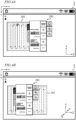
- FIG. 4A is a diagram showing an example of an image displayed on the screen S of the operation terminal 200 in the case of a small shake.
- FIG. 4B is a diagram showing an example of an image displayed on the screen S of the operation terminal 200 in the case of a large shake.
- a uv coordinate system which is fixed on the screen S, with two axes whose origin is at an upper left portion of the screen S.
- the Y axis and the Z axis of the XYZ coordinate system of the work vehicle are also shown.
- the direction in which the u axis extends is parallel to the direction in which the Y axis extends
- the direction in which the v axis extends is parallel to the direction in which the Z axis extends.
- the screen S in the illustrated example is a touch screen panel.
- the image on the screen S includes an input interface 280 to allow a user to perform an input operation.
- the input interface 280 includes an input section with which to input at least one kind of information among information on the work vehicle, information on travel by the work vehicle, and information on work to be performed by the work vehicle.
- the information on the work vehicle includes vehicle speed (km/h), tilling depth (cm), and number of engine revolutions (rpm), for example.
- the information on travel by the work vehicle includes setting of a target path, correction of a target path, switching ON/OFF of the self-driving mode, and emergency stop, for example. Examples of the information on work to be performed by the work vehicle may include a work plan, the kind of task to be performed by the implement, or the like.
- the image on the screen S may further include an indication 290 of at least one kind of information among information on the work vehicle, information on travel by the work vehicle, and information on work to be performed by the work vehicle.
- indications of such information will simply be denoted as the "indication 290".
- the information on the work vehicle included in the indication 290 may include remaining fuel amount (%), water temperature (C°), transmission oil temperature (C°), and the like, for example.
- An example of the information on travel by the work vehicle included in the indication 290 is positional information of a work vehicle that travels along a target path which is set for a field.
- the image on the screen S in the illustrated example includes an indication 290 of a map image that shows the current position of the work vehicle.
- An example of the information on work to be performed by the work vehicle included in the indication 290 is a work history.
- the image on the screen S may further include a camera video that is captured by a camera that is mounted on the work vehicle and the like.
- the controller 230 controls displaying of an image on the screen S.
- the controller 230 generates an image including the input interface 280, and causes the image to be displayed on the screen S.
- the controller 230 may generate an image that further includes the indication 290.
- the input interface 280 illustrated in FIG. 4A includes buttons that are input sections for zooming in or zooming out on the display and buttons to change settings to change the respective ones of vehicle speed and number of engine revolutions. By touching the touch screen panel to manipulate the +/- buttons or the zoom in/zoom out buttons, the user can perform a desired manipulation.
- the image on the screen S that is illustrated in FIG. 4A is only an example, and may include various video indications as aforementioned.
- the controller 230 Based on a vibration of the work vehicle detected by the vibration sensor, the controller 230 changes the position of the indicated input interface 280 on the screen S. To be more specific, when the magnitude of vibration of the work vehicle as detected by the vibration sensor (e.g., amount of displacement in vibration) is below a threshold, i.e., in the case of a small shake, the controller 230 keeps the indicated input interface 280 stationary at a first predetermined position on the screen S.
- the threshold may be set in a range from 5 cm to 10 cm, for example. However, this range for the threshold is only an example, and it is not limiting.
- the indicated input interface 280 may be moved when a vibration of the work vehicle occurs.
- the controller 230 keeps the indication 290 stationary at a second predetermined position on the screen S.
- the controller 230 keeps the indicated input interface 280 and the indication 290 stationary at, respectively, the first and second predetermined positions.
- the input interface 280 is located essentially in the center of the screen S.
- the first predetermined position on the screen S is essentially the center of the screen S.
- a large portion of the indication 290 is located in the left-hand region of the screen S.
- the second predetermined position on the screen S is located to the left of the center of the screen.
- neither the first nor the second predetermined position is limited to the illustrated example.
- Each of the first and second predetermined positions is identified by position coordinates in the uv coordinate system.
- a space to allow movements of the input interface 280 are kept above and below and to the right and the left of the input interface 280 of the screen S.
- the input interface 280 in the illustrated example is displayed at the frontmost, with a portion thereof overlapping a portion of the indication 290. Displaying the input interface 280 at the frontmost allows for improving the operability of the input interface 280.
- the controller 230 moves the indicated input interface 280 from the first predetermined position. More specifically, in the case of a large shake, the controller 230 moves the indicated input interface 280 from the first predetermined position in the same direction as the direction of a displacement in vibration of the work vehicle.
- the amount of movement of the input interface 280 may be determined in accordance with the amount of displacement and the size of the margins on the screen S above and below and to the right and the left of the input interface 280, for example.
- FIG. 4B shows an example of an image displayed on the screen S in a case where a lateral shake occurs.
- the controller 230 moves the indicated input interface 280 from the first predetermined position in the same direction as the direction of a displacement in vibration of the work vehicle (-Z direction), i.e., in the -v direction.
- the input interface 280 moves in the -v direction from the first predetermined position illustrated in FIG. 4A .
- the controller 230 moves the indicated input interface 280 from the first predetermined position in the +v direction. Or, if the work vehicle is displaced in an upper right direction (in the P direction as illustrated) and the magnitude of vibration is equal to or above the threshold, the controller 230 moves the indicated input interface 280 from the first predetermined position in the P direction as illustrated.
- the magnitude of vibration is equal to or above the threshold, i.e., in the case of a large shake, a driver sitting in the driver's seat is shaken to a relatively large extent with a low frequency.
- the driver may make a turning operation at a headland while changing the speed or the number of engine revolutions.
- the work vehicle is liable to shake during a turn at a headland, and therefore the operability of the input interface displayed on the screen has not necessarily been good.
- the controller 230 moves the indicated input interface 280 from the first predetermined position in the same direction as the direction of a displacement in vibration of the work vehicle.
- the input interface 280 moves in the direction of a displacement in vibration of the work vehicle. This can make it easier for a driver who is shaken by a vibration or a tilt of the work vehicle to manipulate the input interface 280 displayed on the screen S with a finger, for example.
- FIG. 5A is a diagram showing another example of an image displayed on the screen S of the operation terminal 200 in the case of a small shake.
- FIG. 5B is a diagram showing another example of an image displayed on the screen of the operation terminal 200 in the case of a large shake.
- a uv coordinate system is shown in each of FIG. 5A and FIG. 5B , and also the Y axis and the Z axis of the XYZ coordinate system of the work vehicle are shown for reference sake.
- the image on the screen S in the illustrated example includes the input interface 280 and the indication 290.
- the input interface 280 includes ten keys for the user to input a number.
- the indication 290 includes information on the work vehicle.
- the input interface 280 in the case of a small shake, is located essentially in the center of screen.
- the first predetermined position on the screen S is essentially the center of the screen S.
- the indication 290 is located in the left-hand region of the screen S.
- the second predetermined position on the screen S is located to the left of the center of the screen.
- neither the first nor the second predetermined position is limited to the illustrated example.
- a space to allow movements of the input interface 280 are kept above and below and to the right and the left of the input interface 280 on the screen S.
- FIG. 5B shows an example of an image displayed on the screen S in a case where a lateral shake occurs.
- the controller 230 moves the indicated input interface 280 from the first predetermined position in the same direction as the direction of a displacement in vibration of the work vehicle (+Z direction), i.e., in the +v direction.
- the input interface 280 moves in the +v direction from the first predetermined positioned in FIG. 5A .
- the controller 230 may move the indication 290 in the same direction as the direction of a displacement in vibration of the work vehicle from the second predetermined position. As illustrated in FIG. 5B , if the work vehicle is displaced in the +Z direction and the magnitude of vibration is equal to or above the threshold, the controller 230 may move the indication 290 in the +v direction from the second predetermined position. In this example, because of a lateral shake of the work vehicle, the indication 290 also moves in the +v direction from the first predetermined position illustrated in FIG. 5A .
- the controller 230 may move the indication 290 in the P direction as illustrated, from the second predetermined position.
- the amount of movement of the indication 290 may be determined in accordance with the amount of displacement and the size of the margins on the screen S above and below and to the right and the left of the input interface 290, for example.
- the amount of movement of the input interface 280 and the amount of movement of the indication 290 may be the same or different from each other.
- a display system may include a light source to be controlled by the controller and optics to create a virtual image ahead of the screen in response to received light that is emitted from the light source.
- the display system may include an HUD.
- HUDs that render information for viewing on a person's field of view are used in assisting driving, by displaying information on the windshield of a vehicle.
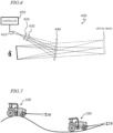
- FIG. 6 is a schematic diagram showing an example configuration of an HUD unit. As one approach to HUD, an approach using virtual image optics is described below. However, the configuration of the HUD unit is not limited to the example shown in FIG. 6 .
- the HUD unit 400 includes a light source 410, a transmission-type screen 420, a field lens 430, and a combiner 440.
- the optics of the HUD unit 400 includes the transmission-type screen 420, the field lens 430, and the combiner 440, and may further include an MEME mirror(s), a movable lens(es) and the like.
- the HUD unit 400 is attached to a ceiling surface of the roof inside the cabin of the work vehicle, for example.
- a light beam that is emitted from the light source 410 is converged by the transmission-type screen 420 to create a real image.
- the transmission-type screen 420 functions as a secondary light source which emits the converged light beam toward the combiner 440 so as to result in a substantially rectangular irradiated area.
- the combiner 440 forms a virtual image based on the radiated light beam. As a result, together with the landscape, the driver is able to recognize a video through the combiner 440.
- the light source 410 is a device that performs video rendering.
- the light source 410 is configured to emit display light toward the transmission-type screen 420.
- Known examples of approaches to rendering are methods based on DLP (Digital Light Processing) and approaches using a laser projector.
- the light source 410 may include a laser projector and a MEME mirror(s) to achieve scanning with the light beam emitted from the laser projector.
- An example of the laser projector is an RGB laser projector.
- the transmission-type screen 420 includes a microlens array at the light-receiving surface side.
- the transmission-type screen 420 performs the function of broadening the incident beam.
- the field lens 430 is disposed between the transmission-type screen 420 and the combiner 440, so as to be near the transmission-type screen 420.
- the field lens 430 is composed of a convex lens, for example, and changes the direction of travel of the light beam emitted from the transmission-type screen 420. Use of the field lens 430 can further enhance the efficiency of light utilization. However, the field lens 430 is not essential.
- the combiner 440 reflects a divergent light beam from the transmission-type screen 420 and forms a virtual image of light.
- the combiner 440 has the function of causing the video formed at the transmission-type screen 420 to be displayed in an enlarged form at a farther distance, and the function of displaying the video as an overlay on the landscape.
- the combiner 440 may sometimes be referred to as the screen.
- the driver is able to recognize the video through the combiner 440, together with the landscape. In other words, together with the landscape, the driver can recognize a video that is rendered on the screen.
- the size of the virtual image or the position at which the virtual image is created can be changed.
- the controller 450 is identical in structure to the aforementioned controller 230 of the operation terminal 200, and is configured to perform the same function. Therefore, any detailed description thereof is omitted.
- FIG. 8A is a diagram showing an example of an image displayed on the screen S in the case of a small shake.
- FIG. 8B is a diagram showing an example of an image displayed on the screen S in the case of a large shake.
- a uv coordinate system is shown in each of FIG. 8A and FIG. 8B , and also the Y axis and the Z axis of the XYZ coordinate system of the work vehicle are shown for reference sake.
- the screen S in the illustrated example is the combiner 440 of the HUD unit 400.
- the windshield of the work vehicle may function as the screen, as will be described below.
- the image on the screen S includes an input interface 480 to allow a user to perform an input operation.
- the input interface 480 in the illustrated example includes an operation button to instruct the work vehicle to begin self-driving, and an operation button for causing an emergency stop of the work vehicle which is traveling via self-driving.
- the image on the screen S in the illustrated example further includes an indication 491 of information on the work vehicle (hereinafter simply referred to as the "indication 491 ”) and an indication 492 of information on travel by the work vehicle (hereinafter simply referred to as the "indication 492 ").
- the indication 492 is a line indication that represents a target path.
- the input interface 480, the indication 491, and the indication 492 are superposed on the external landscape of the windshield 500.
- the input interface 480 may be displayed at the frontmost.
- the input interface 480 (e.g., an operation button) being displayed on the screen S can be remotely manipulated.
- the display system may include an infrared camera for detecting a line of sight of the driver.
- the infrared camera is disposed at an upper portion of the windshield 500 so as to be located ahead of the driver.
- the controller 450 processes data that is output from the infrared camera in order to detect the driver's line of sight.
- the controller 450 can cause the work vehicle to perform a predetermined operation that is assigned to that operation button.
- the input interface 480 is located in a lower portion of the screen S.
- the first predetermined position on the screen S is the lower portion of the screen S.
- the indication 491 is located in an upper region on the left-hand side of the screen S.
- the second predetermined position on the screen S is located in the upper region on the left-hand side of the screen S.
- the indication 492 is displayed along a target path that is set on the ground surface of the field.
- FIG. 7 is a diagram showing work vehicles 100 traveling in a field with ups and downs. On the right side and the left side of FIG. 7 , respectively, work vehicles 100 that are at an ascending slope and a descending slope are illustrated. The work vehicles 100 shown on the right side and the left side of FIG. 7 undergo pitching by an angle ⁇ , in a looking-up direction and a looking-down direction, respectively.
- FIG. 8A and FIG. 8B illustrate examples of superposed images before and after, respectively, the work vehicle 100 shown on the right side of FIG. 7 begins on the ascending slope.
- FIG. 8B shows an example of an image displayed on the screen S in a case where a vertical shake occurs.
- the controller 450 moves the indicated input interface 480 from the first predetermined position in the same direction as the direction of a displacement in vibration of the work vehicle (+Y direction), i.e., in the -u direction.
- the input interface 480 moves from the lower portion to the upper portion of the screen S.
- the controller 450 moves the indicated input interface 480 from the first predetermined position in the P direction as illustrated.
- the controller 450 may move each of the indication 491 and the indication 492 from the second predetermined position in an opposite direction of the direction of a displacement in vibration of the work vehicle (+Y direction), i.e., in the +u direction.
- each of the indication 491 and the indication 492 moves in an opposite direction of the direction in which the input interface 480 moves.
- the windshield 500 in the illustrated example functions as the screen S.
- the controller 450 dynamically changes the position of the displaying region 600 of a video in the uv coordinate system of the screen S.
- the controller 450 dynamically changes the relative position of the displaying region 600 with respect to the windshield 500.
- the movement of the displaying region 600 on the screen S can be achieved by changing the angle(s) of e.g. the MEMS mirror(s) and/or movable lens(es) that are included in the optics of the HUD unit 400.
- FIG. 9B shows an example of an image displayed on the screen S in a case where in a case where a vertical shake occurs.
- the controller 450 moves the indicated input interface 480 from the first predetermined position in the same direction as the direction of a displacement in vibration of the work vehicle (-Y direction), i.e., in the +u direction.
- the input interface 480 moves downward from the first predetermined position shown in FIG. 9A .
- the input interface 480 moves downward from the first predetermined position shown in FIG. 9A .
- the controller 450 may move each of the indication 491 and the indication 492 from the second predetermined position in an opposite direction of the direction of a displacement in vibration of the work vehicle (-Y direction), i.e., in the -u direction.
- -Y direction a displacement in vibration of the work vehicle
- each of the indication 491 and the indication 492 moves upward from the second predetermined position shown in FIG. 9A .
- the displayed position of each of the indication 491 and the indication 492 does not change before and after the displacement.
- FIG. 9B when the input interface 480 and the indication 491 overlap each other, the input interface 480 may be displayed at the frontmost.
- a work vehicle includes a vibration sensor and the aforementioned display system.
- the techniques according to the present disclosure are applied to a work vehicle having the self-traveling function, e.g., a tractor as one example of an agricultural machine, will mainly be described.
- the self-traveling function is not essential.
- the techniques according to the present disclosure are also applicable to construction machines.
- a travel control system for realizing the self-traveling function is mounted in a work vehicle. At least some functions of the travel control system may be implemented by another device (e.g., a server) that communicates with the work vehicle.
- the work vehicle 100 includes a vehicle body 101, a prime mover (engine) 102, and a transmission 103.
- running gear which includes wheels 104 with tires, and a cabin 105 are provided.
- the running gear includes four wheels 104, and axles to cause four wheels to rotate, and brakes to brake on each axle.
- the wheels 104 include a pair of front wheels 104F and a pair of rear wheels 104R .
- a driver's seat 107, a steering device 106, an operation terminal 200, and switches for manipulation are provided inside the cabin 105.
- the front wheels 104F and/or the rear wheels 104R may be replaced by a plurality of wheels with a track (crawlers); rather than wheels with tires, attached thereto.
- the plurality of obstacle sensors 130 shown in FIG. 11 are provided at the front and the rear of the cabin 105.
- the obstacle sensors 130 may be disposed at other positions.
- one or more obstacle sensors 130 may be disposed at any position at the sides, the front, or the rear of the vehicle body 101.
- the obstacle sensors 130 may include, for example, laser scanners or ultrasonic sonars.
- the obstacle sensors 130 may be used to detect obstacles in the surroundings during self-traveling to cause the work vehicle 100 to halt or detour around the obstacles.
- the LiDAR sensor 140 may be used as one of the obstacle sensors 130.
- the controller of the work vehicle 100 may utilize, for positioning, the sensor data acquired with the sensing devices such as the cameras 120 or the LIDAR sensor 140, in addition to the positioning results provided by the GNSS unit 110.
- the position and the orientation of the work vehicle 100 can be estimated with a high accuracy based on data that is acquired with the cameras 120 or the LiDAR sensor 140 and on an environment map that is previously stored in the storage device.
- By correcting or complementing position data based on the satellite signals using the data acquired with the cameras 120 or the LiDAR sensor 140 it becomes possible to identify the position of the work vehicle 100 with a higher accuracy.
- the steering device 106 includes a steering wheel, a steering shaft connected to the steering wheel, and a power steering device to assist in the steering by the steering wheel.
- the front wheels 104F are the wheels responsible for steering, such that changing their angle of turn (also referred to as "steering angle") can cause a change in the traveling direction of the work vehicle 100.
- the steering angle of the front wheels 104F can be changed by manipulating the steering wheel.
- the power steering device includes a hydraulic device or an electric motor to supply an assisting force for changing the steering angle of the front wheels 104F.
- the steering angle may be automatically adjusted by the power of the hydraulic device or the electric motor.
- the implement 300 shown in FIG. 11 is a rotary tiller
- the implement 300 is not limited to a rotary tiller.
- any arbitrary implement such as a seeder, a spreader, a transplanter, a mower, a rake, a baler, a harvester, a sprayer, or a harrow, can be connected to the work vehicle 100 for use.
- the work vehicle 100 in the example of FIG. 12 includes sensors 150 to detect the operating status of the work vehicle 100, a control system 160, a communicator 190, operation switches 191, a buzzer 192, and a drive device 193. These component elements are communicably connected to one another via a bus.
- the GNSS unit 110 includes a GNSS receiver 111, an RTK receiver 112, an IMU 115, and a processing circuit 116.
- the sensors 150 include a steering wheel sensor 152, an angle-of-turn sensor 154, and an axle sensor 156.
- the control system 160 includes a storage device 170 and a controller 180.
- the controller 180 includes a plurality of electronic control units (ECU) 181 to 185.
- the implement 300 includes a drive device 340, a controller 380, and a communicator 390. Note that FIG. 12 shows component elements which are relatively closely related to the operations of self-driving by the work vehicle 100, while other components are omitted from illustration.
- the GNSS unit 110 shown in FIG. 3 performs positioning of the work vehicle 100 by utilizing an RTK (Real Time Kinematic) -GNSS.
- FIG. 13 is a conceptual diagram showing an example of the work vehicle 100 performing positioning based on the RTK-GNSS.
- the reference station 60 may be disposed near the field where the work vehicle 100 performs tasked travel (e.g., at a position within 10 km of the work vehicle 100).
- the positioning method is not limited to being performed by using an RTK-GNSS; any arbitrary positioning method (e.g., an interferometric positioning method or a relative positioning method) that provides positional information with the necessary accuracy can be used.
- positioning may be performed by utilizing a VRS (Virtual Reference Station) or a DGPS (Differential Global Positioning System).
- VRS Virtual Reference Station
- DGPS Different Global Positioning System
- positional information with the necessary accuracy can be obtained without the use of the correction signal transmitted from the reference station 60
- positional information may be generated without using the correction signal.
- the GNSS unit 110 does not need to include the RTK receiver 112.
- the position of the work vehicle 100 is estimated by another method with no use of the signal from the RTK receiver 112.
- the position of the work vehicle 100 may be estimated by matching the data that is output from the LiDAR sensor 140 and/or the cameras 120 against a highly accurate environment map.
- the GNSS unit 110 further includes the IMU 115.
- the IMU 115 may include a 3-axis accelerometer and a 3-axis gyroscope.
- the IMU 115 may include a direction sensor such as a 3-axis geomagnetic sensor.
- the IMU 115 functions as a motion sensor which can output signals representing parameters such as acceleration, velocity, displacement, and attitude of the work vehicle 100.
- the processing circuit 116 can estimate the position and orientation of the work vehicle 100 with a higher accuracy.
- the signal that is output from the IMU 115 may be used for the correction or complementation of the position that is calculated based on the satellite signals and the correction signal.
- the IMU 115 outputs a signal more frequently than the GNSS receiver 111. Utilizing this signal that is output highly frequently, the processing circuit 116 allows the position and orientation of the work vehicle 100 to be measured more frequently (e.g., about 10 Hz or above). Instead of the IMU 115, a 3-axis accelerometer and a 3-axis gyroscope may be separately provided. The IMU 115 may be provided as a separate device from the GNSS unit 110.
- the IMU 115 functions as the aforementioned vibration sensor.
- the work vehicle 100 may include any other IMU that is different from the IMU 115 as a vibration sensor.
- the aforementioned controller 230 or 450 is communicatively connected to the IMU 115 via a bus, for example. As a result, the controller 230 or 450 can acquire data that is output from the IMU 115, and measure the magnitude of vibration of the work vehicle 100.
- the cameras 120 are imagers that image the surrounding environment of the work vehicle 100.
- Each camera 120 includes an image sensor such as a CCD (Charge Coupled Device) or a CMOS (Complementary Metal Oxide Semiconductor), for example.
- each camera 120 may include an optical system including one or more lenses and a signal processing circuit.
- the cameras 120 image the surrounding environment of the work vehicle 100, and generate image (e.g., motion picture) data.
- the cameras 120 are able to capture motion pictures at a frame rate of 3 frames/second (fps: frames per second) or greater, for example.
- the images generated by the cameras 120 may be used by a remote supervisor to check the surrounding environment of the work vehicle 100 with the terminal device 400, for example.
- the images generated by the cameras 120 may also be used for the purpose of positioning or detection of obstacles.
- the plurality of cameras 120 may be provided at different positions on the work vehicle 100, or a single camera 120 may be provided.
- a visible light camera(s) to generate visible light images and an infrared camera(s) to generate infrared images may be separately provided. Both of a visible light camera(s) and an infrared camera(s) may be provided as cameras for generating images for monitoring purposes.
- the infrared camera(s) may also be used for detection of obstacles at nighttime.
- the obstacle sensors 130 detect objects existing in the surroundings of the work vehicle 100.
- Each obstacle sensor 130 may include a laser scanner or an ultrasonic sonar, for example.
- the obstacle sensor 130 When an object exists at a position within a predetermined distance from an obstacle sensor 130, the obstacle sensor 130 outputs a signal indicating the presence of the obstacle.
- the plurality of obstacle sensors 130 may be provided at different positions on the work vehicle 100.
- a plurality of laser scanners and a plurality of ultrasonic sonars may be disposed at different positions on the work vehicle 100. Providing such a great number of obstacle sensors 130 can reduce blind spots in monitoring obstacles in the surroundings of the work vehicle 100.
- the steering wheel sensor 152 measures the angle of rotation of the steering wheel of the work vehicle 100.
- the angle-of-turn sensor 154 measures the angle of turn of the front wheels 104F, which are the wheels responsible for steering. Measurement values by the steering wheel sensor 152 and the angle-of-turn sensor 154 are used for steering control by the controller 180.
- the axle sensor 156 measures the rotational speed, i.e., the number of revolutions per unit time, of an axle that is connected to the wheels 104.
- the axle sensor 156 may be a sensor including a magnetoresistive element (MR), a Hall generator, or an electromagnetic pickup, for example.
- the axle sensor 156 outputs a numerical value indicating the number of revolutions per minute (unit: rpm) of the axle, for example.
- the axle sensor 156 is used to measure the speed of the work vehicle 100.
- the drive device 193 includes various types of devices required to cause the work vehicle 100 to travel and to drive the implement 300; for example, the prime mover 102, the transmission 103, the steering device 106, the linkage device 108 and the like described above.
- the prime mover 102 may include an internal combustion engine such as, for example, a diesel engine.
- the drive device 193 may include an electric motor for traction instead of, or in addition to, the internal combustion engine.
- the buzzer 192 is an audio output device to present an alarm sound to alert the user of an abnormality.
- the buzzer 192 may present an alarm sound when an obstacle is detected during self-driving.
- the buzzer 192 is controlled by the controller 180.
- the storage device 170 includes one or more storage media such as a flash memory or a magnetic disc.
- the storage device 170 stores various data that is generated by the GNSS unit 110, the cameras 120, the obstacle sensors 130, the LiDAR sensor 140, the sensors 150, and the controller 180.
- the data that is stored by the storage device 170 may include map data on the environment where the work vehicle 100 travels (environment map) and data on a target path for self-driving.
- the environment map includes information on a plurality of fields where the work vehicle 100 performs agricultural work and roads around the fields.
- the environment map and the target path may be generated by a processor in a server that keeps agricultural work under management.
- the controller 180 may have a function of generating or editing an environment map and a target path.
- the controller 180 can edit the environment map and the target path, acquired from the server, in accordance with the environment where the work vehicle 100 travels.
- the storage device 170 also stores data on a work plan received by the communicator 190 from the
- the storage device 170 also stores a computer program(s) to cause each of the ECUs in the controller 180 to perform various operations described below.
- a computer program(s) may be provided to the work vehicle 100 via a storage medium (e.g., a semiconductor memory, an optical disc, etc.) or through telecommunication lines (e.g., the Internet).
- a storage medium e.g., a semiconductor memory, an optical disc, etc.
- telecommunication lines e.g., the Internet
- Such a computer program(s) may be marketed as commercial software.
- the controller 180 includes the plurality of ECUs.
- the plurality of ECUs include, for example, the ECU 181 for speed control, the ECU 182 for steering control, the ECU 183 for implement control, the ECU 184 for self-driving control, and the ECU 185 for path generation.
- the ECU 181 controls the prime mover 102, the transmission 103, and brakes included in the drive device 193, thus controlling the speed of the work vehicle 100.
- the ECU 182 controls the hydraulic device or the electric motor included in the steering device 106 based on a measurement value of the steering wheel sensor 152, thus controlling the steering of the work vehicle 100.
- the ECU 183 controls the operations of the three-point link, the PTO shaft and the like that are included in the linkage device 108. Also, the ECU 183 generates a signal to control the operation of the implement 300, and transmits this signal from the communicator 190 to the implement 300.
- the ECU 184 Based on data output from the GNSS unit 110, the cameras 120, the obstacle sensors 130, the LiDAR sensor 140, and the sensors 150, the ECU 184 performs computation and control for achieving self-driving. For example, the ECU 184 specifies the position of the work vehicle 100 based on the data output from at least one of the GNSS unit 110, the cameras 120, and the LiDAR sensor 140. Inside the field, the ECU 184 may determine the position of the work vehicle 100 based only on the data output from the GNSS unit 110. The ECU 184 may estimate or correct the position of the work vehicle 100 based on the data acquired with the cameras 120 or the LiDAR sensor 140.
- the ECU 184 estimates the position of the work vehicle 100 by using the data output from the LiDAR sensor 140 or the cameras 120. For example, the ECU 184 may estimate the position of the work vehicle 100 by matching the data output from the LiDAR sensor 140 or the cameras 120 against the environment map. During self-driving, the ECU 184 performs computation necessary for the work vehicle 100 to travel along a target path, based on the estimated position of the work vehicle 100. The ECU 184 sends the ECU 181 a command to change the speed, and sends the ECU 182 a command to change the steering angle.
- the ECU 181 controls the prime mover 102, the transmission 103, or the brakes to change the speed of the work vehicle 100.
- the ECU 182 controls the steering device 106 to change the steering angle.
- the ECU 185 During travel of the work vehicle 100, based on data output from the cameras 120, the obstacle sensors 130, and the LiDAR sensor 140, the ECU 185 recognizes obstacles existing in the surroundings of the work vehicle 100. Moreover, the ECU 185 may determine a moving destination of the work vehicle 100 based on a work plan stored in the storage device 170, and determine a target path from a start point to a destination point of movement of the work vehicle 100.
- the controller 180 realizes self-driving.
- the controller 180 controls the drive device 193 based on the measured or estimated position of the work vehicle 100 and on the target path.
- the controller 180 can cause the work vehicle 100 to travel along the target path.
- a plurality of ECUs included in the controller 180 may work in cooperation to perform these processes.
- the plurality of ECUs included in the controller 180 can communicate with one another in accordance with a vehicle bus standard such as, for example, a CAN (Controller Area Network). Instead of a CAN, faster communication methods such as Automotive Ethernet (registered trademark) may be used.
- a vehicle bus standard such as, for example, a CAN (Controller Area Network).
- CAN Controller Area Network
- faster communication methods such as Automotive Ethernet (registered trademark) may be used.
- the ECUs 181 to 185 are illustrated as individual blocks in FIG. 12 , the function of each of the ECU 181 to 185 may be implemented by a plurality of ECUs. Alternatively, an onboard computer that integrates the functions of at least some of the ECUs 181 to 185 may be provided.
- the controller 180 may include ECUs other than the ECUs 181 to 185, and any number of ECUs may be provided in accordance with functionality.
- Each ECU includes a processing circuit including one or more processors.
- the communicator 190 is a device including a circuit communicating with the implement 300, the terminal device 400, and a server that keeps agricultural work under management.
- the communicator 190 includes circuitry to perform exchanges of signals complying with an ISOBUS standard such as ISOBUS-TIM, for example, between itself and the communicator 390 of the implement 300. This allows the implement 300 to perform a desired operation, or allows information to be acquired from the implement 300.
- the communicator 190 may further include an antenna and a communication circuit to exchange signals via a network with the respective communicators of the terminal device and the server.
- the network may include a 3G, 4G, 5G, or any other cellular mobile communications network and the Internet, for example.
- the communicator 190 may have a function of communicating with a mobile terminal that is used by a supervisor who is situated near the work vehicle 100. With such a mobile terminal, communication may be performed based on any arbitrary wireless communication standard, e.g., Wi-Fi (registered trademark), 3G, 4G, 5G or any other cellular mobile communication standard, or Bluetooth (registered trademark).
- Wi-Fi registered trademark
- 3G, 4G, 5G any other cellular mobile communication standard
- Bluetooth registered trademark
- the drive device 340 in the implement 300 shown in FIG. 12 performs operations necessary for the implement 300 to perform predetermined work.
- the drive device 340 includes a device suitable for uses of the implement 300, for example, a hydraulic device, an electric motor, a pump or the like.
- the controller 380 controls the operation of the drive device 340.
- the controller 380 causes the drive device 340 to perform various operations.
- a signal that is in accordance with the state of the implement 300 can be transmitted from the communicator 390 to the work vehicle 100.
- the work vehicle 100 can automatically travel both inside and outside a field.
- the work vehicle 100 drives the implement 300 to perform predetermined agricultural work while traveling along a previously-set target path.
- the work vehicle 100 Upon detecting an obstacle with the obstacle sensors 130 while traveling inside the field, the work vehicle 100 halts traveling and performs operations of presenting an alarm sound from the buzzer 192, transmitting an alert signal to the terminal device and the like.
- the positioning of the work vehicle 100 is performed based mainly on data output from the GNSS unit 110.
- the work vehicle 100 automatically travels along a target path set for an agricultural road or a general road outside the field.
- the work vehicle 100 While traveling outside the field, the work vehicle 100 utilizes the data acquired by the cameras 120 or the LiDAR sensor 140. When an obstacle is detected outside the field, the work vehicle 100 avoids the obstacle or halts in that place. Outside the field, the position of the work vehicle 100 is estimated based on data output from the LiDAR sensor 140 or the cameras 120 in addition to positioning data output from the GNSS unit 110.
- the display systems according to the foregoing embodiment may be mounted on a work vehicle (agricultural machine or a construction machine) lacking such functions as an add-on. Such systems may be manufactured and sold independently from the agricultural machine. A computer program for use in such systems may also be manufactured and sold independently from the work vehicle.
- the computer program may be provided in a form stored in a computer-readable, non-transitory storage medium, for example.
- the computer program may also be provided through downloading via telecommunication lines (e.g., the Internet).
- the present disclosure encompasses display systems and work vehicles as recited in the following Items.
- the display system of Item 1 wherein the controller keeps the indicated input interface stationary at a first predetermined position on the screen when a magnitude of vibration of the work vehicle as detected by the vibration sensor is below a threshold, and moves the indicated input interface from the first predetermined position when the magnitude of vibration of the work vehicle is equal to or above the threshold.
Landscapes
- Engineering & Computer Science (AREA)
- Chemical & Material Sciences (AREA)
- Combustion & Propulsion (AREA)
- Transportation (AREA)
- Mechanical Engineering (AREA)
- Theoretical Computer Science (AREA)
- Physics & Mathematics (AREA)
- General Physics & Mathematics (AREA)
- General Engineering & Computer Science (AREA)
- Human Computer Interaction (AREA)
- Software Systems (AREA)
- Computer Hardware Design (AREA)
- Optics & Photonics (AREA)
- User Interface Of Digital Computer (AREA)
- Controls And Circuits For Display Device (AREA)
Abstract
Description
- The present disclosure relates to display systems and work vehicles.
- Techniques have been developed for improving the visual recognition of a video that is being displayed on a screen or a display within a vehicle that may vibrate or tilt because of bumps and dents on the road surface or acceleration/deceleration of the vehicle, etc.
-
Patent Document 1 discloses a head-up display system that corrects the displayed position of a displayed object based on angular rate information in biaxial directions, such information being acquired from a gyroscope.Patent Document 2 discloses a head-up display device that allows a virtual image to be superposed properly on an actual landscape in accordance with the traveling situation of a vehicle.Patent Document 3 discloses a car navigation system in which vibrations of a user's finger cause a certain range out of a displaying region to be displayed with enlargement. - In all of the techniques disclosed in
Patent Documents 1 to 3, an object within the video is shifted in an opposite direction of the direction of a displacement in vibration (i.e., in a direction of canceling out the displacement in vibration), thereby allowing for suppressing incorrect locations of the object as may be caused by the vibration of the vehicle. -
- Patent Document 1: International Publication No.
2020/084954 - Patent Document 2: International Publication No.
2017/134865 - Patent Document 3: International Publication No.
2010/064389 - When a work vehicle vibrates or tilts, the operability of an input interface to be displayed on a screen is to be improved.
- A display system according to one implementation of the present disclosure is a display system to be mounted on a work vehicle including a vibration sensor, the display system including: a screen; and a controller to control displaying of an image on the screen and generate an image including an input interface to allow a user to perform an input operation and cause the image to be displayed on the screen, wherein the controller changes an indicated position of the input interface on the screen based on a vibration of the work vehicle detected by the vibration sensor.
- A work vehicle according to one implementation of the present disclosure includes a vibration sensor and the display system.
- General or specific aspects of various example preferred embodiments of the present disclosure may be implemented using a device, a system, a method, an integrated circuit, a computer program, a non-transitory computer-readable storage medium, or any combination thereof. The computer-readable storage medium may be inclusive of a volatile storage medium, or a non-volatile storage medium. The device may include a plurality of devices. In the case where the device includes two or more devices, the two or more devices may be disposed within a single apparatus, or divided over two or more separate apparatuses.
- According to embodiments of the present disclosure, when a work vehicle vibrates or tilts, the operability of an input interface to be displayed on a screen can be improved.
-
- [
FIG. 1 ] A diagram showing an example of an operation terminal and an example of operation switches that are provided inside a cabin of a work vehicle. - [
FIG. 2 ] A block diagram illustrating an exemplary hardware configuration of an operation terminal. - [
FIG. 3 ] A diagram for describing a coordinate system and displacement components of vibration of a work vehicle according to an embodiment of the present disclosure. - [
FIG. 4A ] A diagram showing an example of an image displayed on a screen of the operation terminal in the case of a small shake. - [
FIG. 4B ] A diagram showing an example of an image displayed on a screen of the operation terminal in the case of a large shake. - [
FIG. 5A ] A diagram showing another example of an image displayed on a screen of the operation terminal in the case of a small shake. - [
FIG. 5B ] A diagram showing another example of an image displayed on a screen of the operation terminal in the case of a large shake. - [
FIG. 6 ] A schematic diagram showing an example configuration of an HUD unit. - [
FIG. 7 ] A diagram showing work vehicles traveling in a field with ups and downs. - [
FIG. 8A ] A diagram showing an example of an image displayed on the screen in the case of a small shake. - [
FIG. 8B ] A diagram showing an example of an image displayed on the screen in the case of a large shake. - [
FIG. 9A ] A diagram showing another example of an image displayed on the screen in the case of a small shake. - [
FIG. 9B ] A diagram showing another example of an image displayed on the screen in the case of a large shake. - [
FIG. 10 ] A perspective view showing an example appearance of a work vehicle. - [
FIG. 11 ] A side view schematically showing an example of a work vehicle having an implement attached thereto. - [
FIG. 12 ] A block diagram showing example configurations of a work vehicle and an implement. - [
FIG. 13 ] A conceptual diagram showing an example of a work vehicle performing positioning based on an RTK-GNSS. - In the present disclosure, an "agricultural machine" refers to a machine for agricultural applications. Examples of agricultural machines include tractors, harvesters, rice transplanters, vehicles for crop management, vegetable transplanters, mowers, seeders, spreaders, and mobile robots for agriculture. Not only may a work vehicle such as a tractor function as an "agricultural machine" alone by itself, but also a combination of a work vehicle and an implement that is attached to, or towed by, the work vehicle may function as an "agricultural machine". For the ground surface inside a field, the agricultural machine performs agricultural work such as tilling, seeding, preventive pest control, manure spreading, planting of crops, or harvesting. Such agricultural work or tasks may be referred to as "groundwork", or simply as "work" or "tasks". Travel of a vehicle-type agricultural machine performed while the agricultural machine also performs agricultural work may be referred to as "tasked travel".
- "Self-driving" refers to controlling the movement of an agricultural machine by the action of a controller, rather than through manual operations of a driver. An agricultural machine that performs self-driving may be referred to as a "self-driving agricultural machine" or a "robotic agricultural machine". During self-driving, not only the movement of the agricultural machine, but also the operation of agricultural work (e.g., the operation of the implement) may be controlled automatically. In the case where the agricultural machine is a vehicle-type machine, travel of the agricultural machine via self-driving will be referred to as "self-traveling". The controller may be configured or programmed to control at least one of: steering that is required in the movement of the agricultural machine; adjustment of the moving speed, or beginning and ending of a move. In the case of controlling a work vehicle having an implement attached thereto, the controller may control raising or lowering of the implement, beginning and ending of an operation of the implement, and so on. A move based on self-driving may include not only moving of an agricultural machine that goes along a predetermined path toward a destination, but also moving of an agricultural machine that follows a target of tracking. An agricultural machine that performs self-driving may also move partly based on the user's instructions. Moreover, an agricultural machine that performs self-driving may operate not only in a self-driving mode but also in a manual driving mode, where the agricultural machine moves through manual operations of the driver. When performed not manually but through the action of a controller, the steering of an agricultural machine will be referred to as "automatic steering". A portion of, or the entirety of, the controller may reside outside the agricultural machine. Control signals, commands, data, etc., may be communicated between the agricultural machine and a controller residing outside the agricultural machine. An agricultural machine that performs self-driving may move autonomously while sensing the surrounding environment, without any person being involved in the controlling of the movement of the agricultural machine. During an autonomous move, operations of detecting and avoiding obstacles may be performed.
- An "environment map" is data representing, with a predetermined coordinate system, the position or the region of an object existing in the environment where the agricultural machine moves. The environment map may be referred to simply as a "map" or "map data". The coordinate system defining the environment map is, for example, a world coordinate system such as a geographic coordinate system fixed to the globe. Regarding an object existing in the environment, the environment map may include information other than the position (e.g., attribute information or other types of information). The "environment map" encompasses various type of maps such as a point cloud map and a grid map. Data on a local map or a partial map that is generated or processed in a process of constructing the environment map is also referred to as a "map" or "map data".
- An "agricultural road" is a road used mainly for agriculture. An "agricultural road" is not limited to a road paved with asphalt, and encompasses unpaved roads covered with soil, gravel or the like. An "agricultural road" encompasses roads (including private roads) on which only vehicle-type agricultural machines (e.g., work vehicles such as tractors, etc.) are allowed to travel and roads on which general vehicles (cars, trucks, buses, etc.) are also allowed to travel. The work vehicles may automatically travel on a general road in addition to an agricultural road. The "general road" is a road maintained for traffic of general vehicles.
- Hereinafter, preferred embodiments of the present disclosure will be described more specifically. Note however that unnecessarily detailed descriptions may be omitted. For example, detailed descriptions on what is well known in the art or redundant descriptions on what is substantially the same configuration may be omitted. This is to avoid lengthy description, and facilitate the understanding of those skilled in the art. The accompanying drawings and the following description, which are provided by the present inventors so that those skilled in the art can sufficiently understand the present disclosure, are not intended to limit the scope of claims. In the following description, component elements having identical or similar functions are denoted by identical reference numerals.
- The following preferred embodiments are only exemplary, and the techniques according to the present disclosure are not limited to the following preferred embodiments. For example, numerical values, shapes, materials, steps, and orders of steps, layout of a display screen, etc., that are indicated in the following preferred embodiments are only exemplary, and admit of various modifications so long as it makes technological sense. Any one implementation may be combined with another so long as it makes technological sense to do so.
- A display system according to an embodiment of the present disclosure is to be mounted on a work vehicle including a vibration sensor. The work vehicle is capable of human driving, and can perform both of manual driving and self-driving. The display system includes a screen and a controller. Examples of the vibration sensors may be a gyroscope, an acceleration sensor, a combination of a gyroscope and an acceleration sensor, or an inertial measurement unit (IMU). For example, a touch screen panel of an operation terminal, a windshield (or a front panel) of a work vehicle or a combiner of an HUD that renders into view a virtual image created by a head-up display (hereinafter referred to as "HUD"), or the like can function as the screen of the display system.
- The controller is configured to control displaying of an image on the screen, generate an image including an input interface to allow a user to perform an input operation, and cause the image to be displayed on the screen. The controller changes an indicated position of the input interface on the screen based on a vibration of the work vehicle detected by the vibration sensor. For example, when the magnitude of vibration of the work vehicle as detected by the vibration sensor is below a threshold, the controller keeps the indicated input interface stationary at a first predetermined position on the screen, and moves the indicated input interface from the first predetermined position when the magnitude of vibration of the work vehicle is equal to or above the threshold. A magnitude of vibration indicates the magnitude of a velocity, an acceleration, or a displacement of vibration. Unless otherwise specified, the magnitude of vibration in the embodiments of the present disclosure means the magnitude of a displacement in vibration (amount of displacement).
- When the magnitude of vibration of the work vehicle is equal to or above the threshold, the controller according to an embodiment of the present disclosure moves the indicated input interface from the first predetermined position in the same direction as the direction of a displacement in vibration of the work vehicle. Thus, by shifting the indicated input interface in the video in the same direction as the direction of a displacement in vibration, when the work vehicle vibrates or tilts, the input interface displayed on the screen may have an improved operability.
-
FIG. 1 is a diagram showing an example of anoperation terminal 200 and an example of operation switches 191 that are provided inside a cabin of a work vehicle.FIG. 2 is a block diagram illustrating an exemplary hardware configuration of theoperation terminal 200. - Inside the cabin, the operation switches 191, including a plurality of switches that are manipulable by the user, are provided. The operation switches 191 may include, for example, a switch to select the gear shift as to a main gear shift or a range gear shift, a switch to switch between a self-driving mode and a manual driving mode, a switch to switch between forward travel and backward travel, a switch to switch between four-wheel drive and two-wheel drive, a switch to disengage the link between the right and left brakes, a switch to raise or lower the implement, and the like.
- The
operation terminal 200 is a terminal to allow a user to perform manipulations related to the travel of the work vehicle and the operation of the implement, and is also referred to as a virtual terminal (VT). Theoperation terminal 200 may include a display device of a touch screen panel type, and/or one or more buttons. The display device may be a display, e.g., a liquid crystal or organic light-emitting diode (OLED). By manipulating a touch screen panel of theoperation terminal 200, the user can perform various manipulations, such as switching the self-driving mode ON or OFF, switching the remote operation mode ON or OFF, recording or editing of an environment map, setting a target path, changing an amount of control for the work vehicle, e.g., a vehicle speed or a number of engine revolutions, and switching the implement ON or OFF, for example. At least some of these manipulations may also be realized by manipulating the operation switches 191. Theoperation terminal 200 may be configured to be detachable from the work vehicle. A user who is at remote place from the work vehicle may manipulate thedetached operation terminal 200 to control the operation of the work vehicle. - Instead of the
operation terminal 200, a laptop computer may be disposed inside the cabin, the laptop computer including a touch screen panel and having necessary application software installed thereon to change the position of the indicated input interface on the screen based on a vibration of the work vehicle detected by the vibration sensor. Alternatively, a mobile terminal such as a smartphone or a tablet computer having the aforementioned application software installed thereon, etc., may be disposed inside the cabin. - The
operation terminal 200 shown inFIG. 2 includes aninput device 210, adisplay device 220, acontroller 230, aROM 240, aRAM 250, astorage device 260, and acommunicator 270. These component elements are communicably connected to one another via a bus. - The
input device 210 is a device to convert an instruction from the user into data and input the data to a computer. Theinput device 210 may be, for example, a keyboard or a mouse. Thedisplay device 220 may be, for example, a liquid crystal display or an organic EL display. Thedisplay device 220 includes a touch screen panel, and not only functions to display video, but also functions as theinput device 210. - The
controller 230 includes a processor. The processor is a semiconductor integrated circuit including a central processing unit (CPU), for example. The processor may be implemented as a microprocessor or a microcontroller. Alternatively, the processor may be implemented as an FPGA (Field Programmable Gate Array), a GPU (Graphics Processing Unit), an ASIC (Application Specific Integrated Circuit), or an ASSP (Application Specific Standard Product) incorporating a CPU; or a combination of two or more circuits selected from among such circuits. The processor consecutively executes a computer program in which instructions for performing at least one process are stated, this being stored in theROM 240, and realizes a desired process. - The
ROM 240 is, for example, a writable memory (e.g., PROM), a rewritable memory (e.g., flash memory) or a read-only memory. TheROM 240 stores a program to control operations of the processor. TheROM 240 does not need to be a single storage medium, and may be an assembly of a plurality of storage mediums. A portion of the assembly of the plurality of storage media may be a removable memory. - The
RAM 250 provides a work area in which the control program stored in theROM 240 is once laid out at the time of boot. TheRAM 250 does not need to be a single storage medium, and may be an assembly of a plurality of storage mediums. - The
storage device 260 may be, for example, a magnetic storage device or a semiconductor storage device. An example of the magnetic storage device is a hard disk drive (HDD). An example of the semiconductor storage device is a solid state drive (SSD). - The
communicator 270 is a communication module to communicate with, for example, a cloud server that keeps agricultural work under management, a work vehicle, or a terminal device that may be used by the user (farm manager, agricultural worker, etc.) via a network. Thecommunicator 270 can perform wired communication in compliance with communication standards such as, for example, IEEE1394 (registered trademark) or Ethernet (registered trademark). Thecommunicator 270 may perform wireless communication in compliance with the Bluetooth (registered trademark) or Wi-Fi standards, or cellular mobile communication based on 3G, 4G, 5G or any other cellular mobile communication standard. -
FIG. 3 is a diagram for describing a coordinate system and displacement components of vibration of thework vehicle 100. An XYZ coordinate system with three axes that are orthogonal to one another is shown inFIG. 3 . A vibration that may occur in thework vehicle 100 can be expressed as displacement components in directions along the X, Y, and Z axes and a rotational component around each axis. The X axis extends along the front-rear direction of thework vehicle 100. The Y axis extends along the top-bottom (vertical) direction of thework vehicle 100. The Z axis extends along the right-left direction of thework vehicle 100. Translations along the X, Y, and Z axes without involving rotation are called, respectively, a front-rear displacement (X), an up-down displacement (Y), and a right-left displacement (Z). Rotational displacement includes rolling, pitching, and yawing. Rotation around the X axis is called rolling, rotation around the Y axis yawing, and rotation around the Z axis pitching. - In the present specification, when a work vehicle vibrates or tilts, it may be said that "the work vehicle shakes". A work vehicle may shake due to bumps and dents on the road surface of off-road terrain, including fields, acceleration/deceleration or turning of the vehicle, etc., for example. A shake may be expressed in terms of translations along the three axes, rotational displacements along the three axes, or any combination thereof. In embodiments of the present disclosure, among others, a shake that is expressed in terms of a right-left displacement (Z), rolling, or a combination thereof is referred to as a "lateral shake", and a shake that is expressed in terms of an up-down displacement (Y), pitching, or a combination thereof is referred to as a "vertical shake".
- As described below, a work vehicle according to an embodiment of the present disclosure includes an IMU as a vibration sensor. An IMU includes an acceleration sensor and a gyroscope. The acceleration sensor measures translations along the aforementioned three axes. The gyroscope measures rotational displacements along the aforementioned three axes. For example, taking a first-order integral of accelerations along the Y axis direction that are measured by the acceleration sensor produces a velocity, and taking a first-order integral of velocities produces an up-down displacement (Y). Taking a first-order integral of angular rates of rotation around the Z axis measured by the gyroscope produces an angle of rotation. Thus, with the IMU, tilt and vibration of the work vehicle can be measured.
- Hereinafter, an example operation of the controller when a lateral shake or a vertical shake occurs will be described. However, when the work vehicle actually travels on off-road terrain, shakes may occur in any direction. In an embodiment of the present disclosure, the magnitude of a shake is distinguished against a threshold. A shake whose magnitude of displacement in vibration (or whose magnitude of vibration) is below a threshold is referred to, in relative terms, as "a small shake"; a shake whose magnitude of displacement in vibration is equal to or greater than the threshold is referred to as "a large shake" in relative terms. In the case of a large shake, the shake of the work vehicle has a frequency on the order of several Hz to several ten Hz, for example. Therefore, a driver sitting in the driver's seat may be shaken to a relatively large extent by the shake of the work vehicle.
-
FIG. 4A is a diagram showing an example of an image displayed on the screen S of theoperation terminal 200 in the case of a small shake.FIG. 4B is a diagram showing an example of an image displayed on the screen S of theoperation terminal 200 in the case of a large shake. In each ofFIG. 4A and FIG. 4B is shown a uv coordinate system which is fixed on the screen S, with two axes whose origin is at an upper left portion of the screen S. For reference sake, the Y axis and the Z axis of the XYZ coordinate system of the work vehicle are also shown. In embodiments of the present disclosure, for convenience of explanation, the direction in which the u axis extends is parallel to the direction in which the Y axis extends, and the direction in which the v axis extends is parallel to the direction in which the Z axis extends. - The screen S in the illustrated example is a touch screen panel. The image on the screen S includes an
input interface 280 to allow a user to perform an input operation. Theinput interface 280 includes an input section with which to input at least one kind of information among information on the work vehicle, information on travel by the work vehicle, and information on work to be performed by the work vehicle. The information on the work vehicle includes vehicle speed (km/h), tilling depth (cm), and number of engine revolutions (rpm), for example. The information on travel by the work vehicle includes setting of a target path, correction of a target path, switching ON/OFF of the self-driving mode, and emergency stop, for example. Examples of the information on work to be performed by the work vehicle may include a work plan, the kind of task to be performed by the implement, or the like. - The image on the screen S may further include an
indication 290 of at least one kind of information among information on the work vehicle, information on travel by the work vehicle, and information on work to be performed by the work vehicle. Hereinafter, indications of such information will simply be denoted as the "indication 290". In addition to the aforementioned examples, the information on the work vehicle included in theindication 290 may include remaining fuel amount (%), water temperature (C°), transmission oil temperature (C°), and the like, for example. An example of the information on travel by the work vehicle included in theindication 290 is positional information of a work vehicle that travels along a target path which is set for a field. The image on the screen S in the illustrated example includes anindication 290 of a map image that shows the current position of the work vehicle. An example of the information on work to be performed by the work vehicle included in theindication 290 is a work history. The image on the screen S may further include a camera video that is captured by a camera that is mounted on the work vehicle and the like. - The
controller 230 controls displaying of an image on the screen S. Thecontroller 230 generates an image including theinput interface 280, and causes the image to be displayed on the screen S. Thecontroller 230 may generate an image that further includes theindication 290. - The
input interface 280 illustrated inFIG. 4A includes buttons that are input sections for zooming in or zooming out on the display and buttons to change settings to change the respective ones of vehicle speed and number of engine revolutions. By touching the touch screen panel to manipulate the +/- buttons or the zoom in/zoom out buttons, the user can perform a desired manipulation. However, the image on the screen S that is illustrated inFIG. 4A is only an example, and may include various video indications as aforementioned. - Based on a vibration of the work vehicle detected by the vibration sensor, the
controller 230 changes the position of the indicatedinput interface 280 on the screen S. To be more specific, when the magnitude of vibration of the work vehicle as detected by the vibration sensor (e.g., amount of displacement in vibration) is below a threshold, i.e., in the case of a small shake, thecontroller 230 keeps the indicatedinput interface 280 stationary at a first predetermined position on the screen S. The threshold may be set in a range from 5 cm to 10 cm, for example. However, this range for the threshold is only an example, and it is not limiting. For example, the indicatedinput interface 280 may be moved when a vibration of the work vehicle occurs. Furthermore, when the magnitude of vibration of the work vehicle is below the threshold, thecontroller 230 keeps theindication 290 stationary at a second predetermined position on the screen S. Thus, even if the work vehicle has been displaced in a certain direction, if the magnitude of vibration is below the threshold, thecontroller 230 keeps the indicatedinput interface 280 and theindication 290 stationary at, respectively, the first and second predetermined positions. - In the example shown in
FIG. 4A , in the case of a small shake, theinput interface 280 is located essentially in the center of the screen S. In this example, the first predetermined position on the screen S is essentially the center of the screen S. A large portion of theindication 290 is located in the left-hand region of the screen S. In this example, the second predetermined position on the screen S is located to the left of the center of the screen. However, neither the first nor the second predetermined position is limited to the illustrated example. Each of the first and second predetermined positions is identified by position coordinates in the uv coordinate system. - A space to allow movements of the
input interface 280 are kept above and below and to the right and the left of theinput interface 280 of the screen S. Theinput interface 280 in the illustrated example is displayed at the frontmost, with a portion thereof overlapping a portion of theindication 290. Displaying theinput interface 280 at the frontmost allows for improving the operability of theinput interface 280. - When the magnitude of vibration of the work vehicle is equal to or above the threshold, i.e., in the case of a large shake, the
controller 230 moves the indicatedinput interface 280 from the first predetermined position. More specifically, in the case of a large shake, thecontroller 230 moves the indicatedinput interface 280 from the first predetermined position in the same direction as the direction of a displacement in vibration of the work vehicle. The amount of movement of theinput interface 280 may be determined in accordance with the amount of displacement and the size of the margins on the screen S above and below and to the right and the left of theinput interface 280, for example. -
FIG. 4B shows an example of an image displayed on the screen S in a case where a lateral shake occurs. For example, if the work vehicle is displaced in the -Z direction and the magnitude of vibration is equal to or above the threshold, thecontroller 230 moves the indicatedinput interface 280 from the first predetermined position in the same direction as the direction of a displacement in vibration of the work vehicle (-Z direction), i.e., in the -v direction. As a result, because of a lateral shake of the work vehicle, theinput interface 280 moves in the -v direction from the first predetermined position illustrated inFIG. 4A . In another example, if the work vehicle is displaced in the +Z direction and the magnitude of vibration is equal to or above the threshold, thecontroller 230 moves the indicatedinput interface 280 from the first predetermined position in the +v direction. Or, if the work vehicle is displaced in an upper right direction (in the P direction as illustrated) and the magnitude of vibration is equal to or above the threshold, thecontroller 230 moves the indicatedinput interface 280 from the first predetermined position in the P direction as illustrated. - If the magnitude of vibration is equal to or above the threshold, i.e., in the case of a large shake, a driver sitting in the driver's seat is shaken to a relatively large extent with a low frequency. For example, the driver may make a turning operation at a headland while changing the speed or the number of engine revolutions. However, the work vehicle is liable to shake during a turn at a headland, and therefore the operability of the input interface displayed on the screen has not necessarily been good.
- According to an embodiment of the present disclosure, in the case of a large shake, the
controller 230 moves the indicatedinput interface 280 from the first predetermined position in the same direction as the direction of a displacement in vibration of the work vehicle. As a result, theinput interface 280 moves in the direction of a displacement in vibration of the work vehicle. This can make it easier for a driver who is shaken by a vibration or a tilt of the work vehicle to manipulate theinput interface 280 displayed on the screen S with a finger, for example. -
FIG. 5A is a diagram showing another example of an image displayed on the screen S of theoperation terminal 200 in the case of a small shake.FIG. 5B is a diagram showing another example of an image displayed on the screen of theoperation terminal 200 in the case of a large shake. A uv coordinate system is shown in each ofFIG. 5A and FIG. 5B , and also the Y axis and the Z axis of the XYZ coordinate system of the work vehicle are shown for reference sake. - The image on the screen S in the illustrated example includes the
input interface 280 and theindication 290. Theinput interface 280 includes ten keys for the user to input a number. Theindication 290 includes information on the work vehicle. - In the example shown in
FIG. 5A , in the case of a small shake, theinput interface 280 is located essentially in the center of screen. In this example, the first predetermined position on the screen S is essentially the center of the screen S. Theindication 290 is located in the left-hand region of the screen S. In this example, the second predetermined position on the screen S is located to the left of the center of the screen. However, neither the first nor the second predetermined position is limited to the illustrated example. As in the example shown inFIG. 4A , a space to allow movements of theinput interface 280 are kept above and below and to the right and the left of theinput interface 280 on the screen S. -
FIG. 5B shows an example of an image displayed on the screen S in a case where a lateral shake occurs. For example, if the work vehicle is displaced in the +Z direction and the magnitude of vibration is equal to or above the threshold, thecontroller 230 moves the indicatedinput interface 280 from the first predetermined position in the same direction as the direction of a displacement in vibration of the work vehicle (+Z direction), i.e., in the +v direction. As a result, because of a lateral shake of the work vehicle, theinput interface 280 moves in the +v direction from the first predetermined positioned inFIG. 5A . - When the magnitude of vibration of the work vehicle is equal to or above the threshold, i.e., in the case of a large shake, the
controller 230 may move theindication 290 in the same direction as the direction of a displacement in vibration of the work vehicle from the second predetermined position. As illustrated inFIG. 5B , if the work vehicle is displaced in the +Z direction and the magnitude of vibration is equal to or above the threshold, thecontroller 230 may move theindication 290 in the +v direction from the second predetermined position. In this example, because of a lateral shake of the work vehicle, theindication 290 also moves in the +v direction from the first predetermined position illustrated inFIG. 5A . Or, if the work vehicle is displaced in an upper right direction (in the P direction as illustrated) and the magnitude of vibration is equal to or above the threshold, thecontroller 230 may move theindication 290 in the P direction as illustrated, from the second predetermined position. The amount of movement of theindication 290 may be determined in accordance with the amount of displacement and the size of the margins on the screen S above and below and to the right and the left of theinput interface 290, for example. The amount of movement of theinput interface 280 and the amount of movement of theindication 290 may be the same or different from each other. - A display system according to an embodiment of the present disclosure may include a light source to be controlled by the controller and optics to create a virtual image ahead of the screen in response to received light that is emitted from the light source. In other words, the display system may include an HUD. HUDs that render information for viewing on a person's field of view are used in assisting driving, by displaying information on the windshield of a vehicle.
-
FIG. 6 is a schematic diagram showing an example configuration of an HUD unit. As one approach to HUD, an approach using virtual image optics is described below. However, the configuration of the HUD unit is not limited to the example shown inFIG. 6 . - The
HUD unit 400 includes alight source 410, a transmission-type screen 420, afield lens 430, and acombiner 440. The optics of theHUD unit 400 includes the transmission-type screen 420, thefield lens 430, and thecombiner 440, and may further include an MEME mirror(s), a movable lens(es) and the like. TheHUD unit 400 is attached to a ceiling surface of the roof inside the cabin of the work vehicle, for example. - A light beam that is emitted from the
light source 410 is converged by the transmission-type screen 420 to create a real image. The transmission-type screen 420 functions as a secondary light source which emits the converged light beam toward thecombiner 440 so as to result in a substantially rectangular irradiated area. Thecombiner 440 forms a virtual image based on the radiated light beam. As a result, together with the landscape, the driver is able to recognize a video through thecombiner 440. - The
light source 410 is a device that performs video rendering. Thelight source 410 is configured to emit display light toward the transmission-type screen 420. Known examples of approaches to rendering are methods based on DLP (Digital Light Processing) and approaches using a laser projector. Thelight source 410 may include a laser projector and a MEME mirror(s) to achieve scanning with the light beam emitted from the laser projector. An example of the laser projector is an RGB laser projector. - The transmission-
type screen 420 includes a microlens array at the light-receiving surface side. The transmission-type screen 420 performs the function of broadening the incident beam. Thefield lens 430 is disposed between the transmission-type screen 420 and thecombiner 440, so as to be near the transmission-type screen 420. Thefield lens 430 is composed of a convex lens, for example, and changes the direction of travel of the light beam emitted from the transmission-type screen 420. Use of thefield lens 430 can further enhance the efficiency of light utilization. However, thefield lens 430 is not essential. - Although a half mirror is generally used as the
combiner 440, for example, a hologram element or the like may instead be used. Thecombiner 440 reflects a divergent light beam from the transmission-type screen 420 and forms a virtual image of light. Thecombiner 440 has the function of causing the video formed at the transmission-type screen 420 to be displayed in an enlarged form at a farther distance, and the function of displaying the video as an overlay on the landscape. Hereinafter, thecombiner 440 may sometimes be referred to as the screen. As a result of this, the driver is able to recognize the video through thecombiner 440, together with the landscape. In other words, together with the landscape, the driver can recognize a video that is rendered on the screen. Depending on the curvature of thecombiner 440, the size of the virtual image or the position at which the virtual image is created can be changed. - The
controller 450 is identical in structure to theaforementioned controller 230 of theoperation terminal 200, and is configured to perform the same function. Therefore, any detailed description thereof is omitted. -
FIG. 8A is a diagram showing an example of an image displayed on the screen S in the case of a small shake.FIG. 8B is a diagram showing an example of an image displayed on the screen S in the case of a large shake. A uv coordinate system is shown in each ofFIG. 8A and FIG. 8B , and also the Y axis and the Z axis of the XYZ coordinate system of the work vehicle are shown for reference sake. - The screen S in the illustrated example is the
combiner 440 of theHUD unit 400. However, instead of a combiner, the windshield of the work vehicle may function as the screen, as will be described below. The image on the screen S includes aninput interface 480 to allow a user to perform an input operation. Theinput interface 480 in the illustrated example includes an operation button to instruct the work vehicle to begin self-driving, and an operation button for causing an emergency stop of the work vehicle which is traveling via self-driving. The image on the screen S in the illustrated example further includes anindication 491 of information on the work vehicle (hereinafter simply referred to as the "indication 491") and anindication 492 of information on travel by the work vehicle (hereinafter simply referred to as the "indication 492"). In this example, theindication 492 is a line indication that represents a target path. Theinput interface 480, theindication 491, and theindication 492 are superposed on the external landscape of thewindshield 500. Among these indications, theinput interface 480 may be displayed at the frontmost. - In an embodiment of the present disclosure, the input interface 480 (e.g., an operation button) being displayed on the screen S can be remotely manipulated. For example, the display system may include an infrared camera for detecting a line of sight of the driver. The infrared camera is disposed at an upper portion of the
windshield 500 so as to be located ahead of the driver. Thecontroller 450 processes data that is output from the infrared camera in order to detect the driver's line of sight. Upon detecting that the driver's line of sight is directed to an operation button displayed on the screen S, thecontroller 450 can cause the work vehicle to perform a predetermined operation that is assigned to that operation button. An example of a remote operation algorithm based on the driver's line of sight is described inJapanese Laid-Open Patent Publication No. 2022-72453 Japanese Laid-Open Patent Publication No. 2022-72453 - In the example shown in
FIG. 8A , in the case of a small shake, theinput interface 480 is located in a lower portion of the screen S. In this example, the first predetermined position on the screen S is the lower portion of the screen S. Theindication 491 is located in an upper region on the left-hand side of the screen S. In this example, the second predetermined position on the screen S is located in the upper region on the left-hand side of the screen S. However, neither the first nor the second predetermined position is limited to the illustrated example. Theindication 492 is displayed along a target path that is set on the ground surface of the field. -
FIG. 7 is a diagram showingwork vehicles 100 traveling in a field with ups and downs. On the right side and the left side ofFIG. 7 , respectively,work vehicles 100 that are at an ascending slope and a descending slope are illustrated. Thework vehicles 100 shown on the right side and the left side ofFIG. 7 undergo pitching by an angle θ, in a looking-up direction and a looking-down direction, respectively.FIG. 8A and FIG. 8B illustrate examples of superposed images before and after, respectively, thework vehicle 100 shown on the right side ofFIG. 7 begins on the ascending slope. -
FIG. 8B shows an example of an image displayed on the screen S in a case where a vertical shake occurs. As shown inFIG. 7 , if the work vehicle is displaced in the +Y direction (looking-up direction) due to pitching and the magnitude of vibration is equal to or above the threshold, thecontroller 450 moves the indicatedinput interface 480 from the first predetermined position in the same direction as the direction of a displacement in vibration of the work vehicle (+Y direction), i.e., in the -u direction. As a result, because of the vertical shake of the work vehicle, theinput interface 480 moves from the lower portion to the upper portion of the screen S. In another example, if the work vehicle is displaced in an upper right direction (in the P direction as illustrated) and the magnitude of vibration is equal to or above the threshold, thecontroller 450 moves the indicatedinput interface 480 from the first predetermined position in the P direction as illustrated. - When the magnitude of vibration of the work vehicle is equal to or above the threshold, the
controller 450 may move each of theindication 491 and theindication 492 from the second predetermined position in an opposite direction of the direction of a displacement in vibration of the work vehicle. In other words, thecontroller 450 may move each of theindication 491 and theindication 492 from the second predetermined position in a direction of canceling out the displacement in vibration. This allows the displayed position of each of theindication 491 and theindication 492 to be maintained with respect to the landscape. The amounts of movements of theindication 491 and theindication 492 are determined based on the amount of displacement in vibration. - As illustrated in
FIG. 7 , if the work vehicle is displaced in the +Y direction (looking-up direction) due to pitching, and the magnitude of vibration is equal to or above the threshold, thecontroller 450 may move each of theindication 491 and theindication 492 from the second predetermined position in an opposite direction of the direction of a displacement in vibration of the work vehicle (+Y direction), i.e., in the +u direction. As a result, because of the vertical shake of the work vehicle, each of theindication 491 and theindication 492 moves in an opposite direction of the direction in which theinput interface 480 moves. In another example, if the work vehicle is displaced in a lower left direction (in the Q direction as illustrated) and the magnitude of vibration is equal to or above the threshold, thecontroller 450 may move each of theindication 491 and theindication 492 in an upper right direction (in the P direction as illustrated) from the second predetermined position. - With the
HUD unit 400 according to the embodiment of the present disclosure, in the case of a large shake, thecontroller 450 moves the indicatedinput interface 480 from the first predetermined position in the same direction as the direction of a displacement in vibration of the work vehicle. As a result, theinput interface 480 moves in the direction of a displacement in vibration of the work vehicle. This can make it easier for a driver who is shaken by a vibration or a tilt of the work vehicle to manipulate theinput interface 480 indicated on the screen S with a line of sight, for example. Furthermore, in the case of a large shake, thecontroller 450 may move each of theindication 491 and theindication 492 in an opposite direction of the direction of a displacement in vibration of the work vehicle from the second predetermined position. This is advantageous for being able to reduce a superposition offset of theindication 491 with respect to the landscape, and particularly advantageous in terms of being able to reduce a superposition offset of theindication 492 with respect to the ground surface of the field. -
FIG. 9A is a diagram showing another example of an image displayed on the screen S in the case of a small shake.FIG. 9B is a diagram showing another example of an image displayed on the screen S in the case of a large shake. A uv coordinate system is shown in each ofFIG. 9A and FIG. 9B , and also the Y axis and the Z axis of the XYZ coordinate system of the work vehicle are shown for reference sake.FIG. 9A and FIG. 9B illustrate examples of superposed images before and after, respectively, thework vehicle 100 shown on the left side ofFIG. 7 begins on the descending slope. - The
windshield 500 in the illustrated example functions as the screen S. In this example, unlike in the example shown inFIG. 8B , in the case of a large shake, thecontroller 450 dynamically changes the position of the displayingregion 600 of a video in the uv coordinate system of the screen S. In other words, in response to a shake of the work vehicle, thecontroller 450 dynamically changes the relative position of the displayingregion 600 with respect to thewindshield 500. The movement of the displayingregion 600 on the screen S can be achieved by changing the angle(s) of e.g. the MEMS mirror(s) and/or movable lens(es) that are included in the optics of theHUD unit 400. -
FIG. 9B shows an example of an image displayed on the screen S in a case where in a case where a vertical shake occurs. As shown inFIG. 7 , if the work vehicle is displaced in the -Y direction (looking-down direction) due to pitching and the magnitude of vibration is equal to or above the threshold, thecontroller 450 moves the indicatedinput interface 480 from the first predetermined position in the same direction as the direction of a displacement in vibration of the work vehicle (-Y direction), i.e., in the +u direction. As a result, from the standpoint of the uv coordinate system, with a vertical shake of the work vehicle, theinput interface 480 moves downward from the first predetermined position shown inFIG. 9A . From the standpoint of the displayingregion 600, too, theinput interface 480 moves downward from the first predetermined position shown inFIG. 9A . Furthermore, thecontroller 450 may move each of theindication 491 and theindication 492 from the second predetermined position in an opposite direction of the direction of a displacement in vibration of the work vehicle (-Y direction), i.e., in the -u direction. As a result, from the standpoint of the uv coordinate system, each of theindication 491 and theindication 492 moves upward from the second predetermined position shown inFIG. 9A . On the other hand, from the standpoint of the displayingregion 600, the displayed position of each of theindication 491 and theindication 492 does not change before and after the displacement. As illustrated inFIG. 9B , when theinput interface 480 and theindication 491 overlap each other, theinput interface 480 may be displayed at the frontmost. - A work vehicle according to an embodiment of the present disclosure includes a vibration sensor and the aforementioned display system.
- With reference to
FIG. 10 to FIG. 13 , an embodiment in which the techniques according to the present disclosure are applied to a work vehicle having the self-traveling function, e.g., a tractor as one example of an agricultural machine, will mainly be described. However, the self-traveling function is not essential. Without being limited to an agricultural machine such as a tractor, the techniques according to the present disclosure are also applicable to construction machines. Hereinafter, as an example, an embodiment in which a travel control system for realizing the self-traveling function is mounted in a work vehicle will be described. At least some functions of the travel control system may be implemented by another device (e.g., a server) that communicates with the work vehicle. -
FIG. 10 is a perspective view showing an example appearance of thework vehicle 100 according to an embodiment of the present disclosure.FIG. 11 is a side view schematically showing an example of thework vehicle 100 having an implement 300 attached thereto. Thework vehicle 100 according to an embodiment of the present disclosure is an agricultural tractor (work vehicle) having the implement 300 attached thereto. Thework vehicle 100 is not limited to a tractor, and does not need to have the implement 300 attached thereto. - As shown in
FIG. 11 , thework vehicle 100 includes avehicle body 101, a prime mover (engine) 102, and atransmission 103. On thevehicle body 101, running gear, which includeswheels 104 with tires, and acabin 105 are provided. The running gear includes fourwheels 104, and axles to cause four wheels to rotate, and brakes to brake on each axle. Thewheels 104 include a pair offront wheels 104F and a pair ofrear wheels 104R. Inside thecabin 105, a driver'sseat 107, asteering device 106, anoperation terminal 200, and switches for manipulation are provided. In the case where thework vehicle 100 performs tasked travel inside the field, thefront wheels 104F and/or therear wheels 104R may be replaced by a plurality of wheels with a track (crawlers); rather than wheels with tires, attached thereto. - The
work vehicle 100 may include at least one sensing device to sense the surrounding environment of thework vehicle 100, and a processing unit to process sensor data that is output from the at least one sensing device. In the example shown inFIG. 11 , thework vehicle 100 includes a plurality of sensing devices. The sensing devices include a plurality ofcameras 120, aLiDAR sensor 140, and a plurality ofobstacle sensors 130. - The
cameras 120 may be provided at the front/rear/right/left of thework vehicle 100, for example. Thecameras 120 image the surrounding environment of thework vehicle 100 and generate image data. The images acquired with thecameras 120 may be output to the processing unit mounted in thework vehicle 100, and transmitted to a terminal device which is responsible for remote monitoring. The image may be displayed on the screen of theoperation terminal 200, for example. Thecameras 120 may also be used to generate images to allow thework vehicle 100, traveling on a road outside the field (an agricultural road or a general road), to recognize geographic features, obstacles, white lines, road signs, indications or the like in the surroundings. - The
LiDAR sensor 140 in the example shown inFIG. 11 is disposed on a lower portion of a front surface of thevehicle body 101. TheLiDAR sensor 140 may be disposed at any other position. While thework vehicle 100 is traveling mainly outside the field, theLiDAR sensor 140 repeatedly outputs sensor data representing the distances and directions of measurement points on objects existing in the surrounding environment, or two-dimensional or three-dimensional coordinate values of such measurement points. The sensor data that is output from theLiDAR sensor 140 is processed by the controller of thework vehicle 100. The controller can perform localization of thework vehicle 100 by matching the sensor data against the environment map. The controller can further detect an object such as an obstacle existing in the surroundings of thework vehicle 100 based on the sensor data. The controller can utilize an algorithm such as, for example, SLAM (Simultaneous Localization and Mapping) to generate or edit an environment map. Thework vehicle 100 may include a plurality of LiDAR sensors disposed at different positions with different orientations. - The plurality of
obstacle sensors 130 shown inFIG. 11 are provided at the front and the rear of thecabin 105. Theobstacle sensors 130 may be disposed at other positions. For example, one ormore obstacle sensors 130 may be disposed at any position at the sides, the front, or the rear of thevehicle body 101. Theobstacle sensors 130 may include, for example, laser scanners or ultrasonic sonars. Theobstacle sensors 130 may be used to detect obstacles in the surroundings during self-traveling to cause thework vehicle 100 to halt or detour around the obstacles. TheLiDAR sensor 140 may be used as one of theobstacle sensors 130. - The
work vehicle 100 further includes aGNSS unit 110. TheGNSS unit 110 includes a GNSS receiver. The GNSS receiver may include an antenna to receive a signal(s) from a GNSS satellite(s) and a processor to calculate the position of thework vehicle 100 based on the signal(s) received by the antenna. TheGNSS unit 110 receives satellite signals transmitted from the plurality of GNSS satellites, and performs positioning based on the satellite signals. GNSS is a collective term for satellite positioning systems such as the GPS (Global Positioning System), QZSS (Quasi-Zenith Satellite System, e.g., MICHIBIKI), GLONASS, Galileo, and BeiDou. Although theGNSS unit 110 according to an embodiment of the present disclosure is disposed above thecabin 105, it may be disposed at any other position. - The
GNSS unit 110 may include an IMU. Signals from the IMU can be used to complement position data. The IMU can measure a tilt or a small motion of thework vehicle 100. The data acquired by the IMU can be used to complement the position data based on the satellite signals, so as to improve the performance of positioning. - The controller of the
work vehicle 100 may utilize, for positioning, the sensor data acquired with the sensing devices such as thecameras 120 or theLIDAR sensor 140, in addition to the positioning results provided by theGNSS unit 110. In the case where objects serving as characteristic points exist in the environment that is traveled by thework vehicle 100, as in the case of an agricultural road, a forest road, a general road, or an orchard, the position and the orientation of thework vehicle 100 can be estimated with a high accuracy based on data that is acquired with thecameras 120 or theLiDAR sensor 140 and on an environment map that is previously stored in the storage device. By correcting or complementing position data based on the satellite signals using the data acquired with thecameras 120 or theLiDAR sensor 140, it becomes possible to identify the position of thework vehicle 100 with a higher accuracy. - The
prime mover 102 may be a diesel engine, for example. Instead of a diesel engine, an electric motor may be used. Thetransmission 103 can change the propulsion and the moving speed of thework vehicle 100 through a speed changing mechanism. Thetransmission 103 can also switch between forward travel and backward travel of thework vehicle 100. - The
steering device 106 includes a steering wheel, a steering shaft connected to the steering wheel, and a power steering device to assist in the steering by the steering wheel. Thefront wheels 104F are the wheels responsible for steering, such that changing their angle of turn (also referred to as "steering angle") can cause a change in the traveling direction of thework vehicle 100. The steering angle of thefront wheels 104F can be changed by manipulating the steering wheel. The power steering device includes a hydraulic device or an electric motor to supply an assisting force for changing the steering angle of thefront wheels 104F. When automatic steering is performed, under the control of the controller disposed in thework vehicle 100, the steering angle may be automatically adjusted by the power of the hydraulic device or the electric motor. - A
linkage device 108 is provided at the rear of thevehicle body 101. Thelinkage device 108 includes, e.g., a three-point linkage (also referred to as a "three-point link" or a "three-point hitch"), a PTO (Power Take Off) shaft, a universal joint, and a communication cable. Thelinkage device 108 allows the implement 300 to be attached to, or detached from, thework vehicle 100. Thelinkage device 108 is able to raise or lower the three-point link with a hydraulic device, for example, thus changing the position or attitude of the implement 300. Moreover, motive power can be sent from thework vehicle 100 to the implement 300 via the universal joint. While towing the implement 300, thework vehicle 100 allows the implement 300 to perform a predetermined task. The linkage device may be provided at the front portion of thevehicle body 101. In that case, the implement can be connected at the rear of thework vehicle 100. - Although the implement 300 shown in
FIG. 11 is a rotary tiller, the implement 300 is not limited to a rotary tiller. For example, any arbitrary implement such as a seeder, a spreader, a transplanter, a mower, a rake, a baler, a harvester, a sprayer, or a harrow, can be connected to thework vehicle 100 for use. -
FIG. 12 is a block diagram showing an example configuration of thework vehicle 100 and the implement 300. Thework vehicle 100 and the implement 300 can communicate with each other via a communication cable that is included in thelinkage device 108. Via a network, thework vehicle 100 is able to communicate with a terminal device and a server that keeps agricultural work under management, for example. - In addition to the
GNSS unit 110, thecameras 120, theobstacle sensors 130, theLiDAR sensor 140, and theoperation terminal 200, thework vehicle 100 in the example ofFIG. 12 includessensors 150 to detect the operating status of thework vehicle 100, acontrol system 160, acommunicator 190, operation switches 191, abuzzer 192, and adrive device 193. These component elements are communicably connected to one another via a bus. TheGNSS unit 110 includes aGNSS receiver 111, anRTK receiver 112, anIMU 115, and aprocessing circuit 116. Thesensors 150 include asteering wheel sensor 152, an angle-of-turn sensor 154, and anaxle sensor 156. Thecontrol system 160 includes astorage device 170 and acontroller 180. Thecontroller 180 includes a plurality of electronic control units (ECU) 181 to 185. The implement 300 includes adrive device 340, acontroller 380, and acommunicator 390. Note thatFIG. 12 shows component elements which are relatively closely related to the operations of self-driving by thework vehicle 100, while other components are omitted from illustration. - The
GNSS receiver 111 in theGNSS unit 110 receives satellite signals transmitted from the plurality of GNSS satellites and generates GNSS data based on the satellite signals. The GNSS data is generated in a predetermined format such as, for example, the NMEA-0183 format. The GNSS data may include, for example, the ID number, the angle of elevation, the azimuth angle, and a value representing the reception intensity of each of the satellites from which the satellite signals are received. - The
GNSS unit 110 shown inFIG. 3 performs positioning of thework vehicle 100 by utilizing an RTK (Real Time Kinematic) -GNSS.FIG. 13 is a conceptual diagram showing an example of thework vehicle 100 performing positioning based on the RTK-GNSS. In the positioning based on the RTK-GNSS, not only satellite signals transmitted from a plurality ofGNSS satellites 50, but also a correction signal that is transmitted from areference station 60 is used. Thereference station 60 may be disposed near the field where thework vehicle 100 performs tasked travel (e.g., at a position within 10 km of the work vehicle 100). Thereference station 60 generates a correction signal of, for example, an RTCM format based on the satellite signals received from the plurality ofGNSS satellites 50, and transmits the correction signal to theGNSS unit 110. TheRTK receiver 112, which includes an antenna and a modem, receives the correction signal transmitted from thereference station 60. Based on the correction signal, theprocessing circuit 116 of theGNSS unit 110 corrects the results of the positioning performed by theGNSS receiver 111. Use of the RTK-GNSS enables positioning with an accuracy on the order of several centimeters of errors, for example. Positional information including latitude, longitude, and altitude information is acquired through the highly accurate positioning by the RTK-GNSS. TheGNSS unit 110 calculates the position of thework vehicle 100 as frequently as, for example, one to ten times per second. - Note that the positioning method is not limited to being performed by using an RTK-GNSS; any arbitrary positioning method (e.g., an interferometric positioning method or a relative positioning method) that provides positional information with the necessary accuracy can be used. For example, positioning may be performed by utilizing a VRS (Virtual Reference Station) or a DGPS (Differential Global Positioning System). In the case where positional information with the necessary accuracy can be obtained without the use of the correction signal transmitted from the
reference station 60, positional information may be generated without using the correction signal. In that case, theGNSS unit 110 does not need to include theRTK receiver 112. - Even in the case where the RTK-GNSS is used, at a place where the correction signal from the
reference station 60 cannot be acquired (e.g., on a road far from the field), the position of thework vehicle 100 is estimated by another method with no use of the signal from theRTK receiver 112. For example, the position of thework vehicle 100 may be estimated by matching the data that is output from theLiDAR sensor 140 and/or thecameras 120 against a highly accurate environment map. - The
GNSS unit 110 according to an embodiment of the present disclosure further includes theIMU 115. TheIMU 115 may include a 3-axis accelerometer and a 3-axis gyroscope. TheIMU 115 may include a direction sensor such as a 3-axis geomagnetic sensor. TheIMU 115 functions as a motion sensor which can output signals representing parameters such as acceleration, velocity, displacement, and attitude of thework vehicle 100. Based not only on the satellite signals and the correction signal but also on a signal that is output from theIMU 115, theprocessing circuit 116 can estimate the position and orientation of thework vehicle 100 with a higher accuracy. The signal that is output from theIMU 115 may be used for the correction or complementation of the position that is calculated based on the satellite signals and the correction signal. TheIMU 115 outputs a signal more frequently than theGNSS receiver 111. Utilizing this signal that is output highly frequently, theprocessing circuit 116 allows the position and orientation of thework vehicle 100 to be measured more frequently (e.g., about 10 Hz or above). Instead of theIMU 115, a 3-axis accelerometer and a 3-axis gyroscope may be separately provided. TheIMU 115 may be provided as a separate device from theGNSS unit 110. - In an embodiment of the present disclosure, the
IMU 115 functions as the aforementioned vibration sensor. However, thework vehicle 100 may include any other IMU that is different from theIMU 115 as a vibration sensor. Theaforementioned controller IMU 115 via a bus, for example. As a result, thecontroller IMU 115, and measure the magnitude of vibration of thework vehicle 100. - The
cameras 120 are imagers that image the surrounding environment of thework vehicle 100. Eachcamera 120 includes an image sensor such as a CCD (Charge Coupled Device) or a CMOS (Complementary Metal Oxide Semiconductor), for example. In addition, eachcamera 120 may include an optical system including one or more lenses and a signal processing circuit. During travel of thework vehicle 100, thecameras 120 image the surrounding environment of thework vehicle 100, and generate image (e.g., motion picture) data. Thecameras 120 are able to capture motion pictures at a frame rate of 3 frames/second (fps: frames per second) or greater, for example. The images generated by thecameras 120 may be used by a remote supervisor to check the surrounding environment of thework vehicle 100 with theterminal device 400, for example. The images generated by thecameras 120 may also be used for the purpose of positioning or detection of obstacles. As shown inFIG. 11 , the plurality ofcameras 120 may be provided at different positions on thework vehicle 100, or asingle camera 120 may be provided. A visible light camera(s) to generate visible light images and an infrared camera(s) to generate infrared images may be separately provided. Both of a visible light camera(s) and an infrared camera(s) may be provided as cameras for generating images for monitoring purposes. The infrared camera(s) may also be used for detection of obstacles at nighttime. - The
obstacle sensors 130 detect objects existing in the surroundings of thework vehicle 100. Eachobstacle sensor 130 may include a laser scanner or an ultrasonic sonar, for example. When an object exists at a position within a predetermined distance from anobstacle sensor 130, theobstacle sensor 130 outputs a signal indicating the presence of the obstacle. The plurality ofobstacle sensors 130 may be provided at different positions on thework vehicle 100. For example, a plurality of laser scanners and a plurality of ultrasonic sonars may be disposed at different positions on thework vehicle 100. Providing such a great number ofobstacle sensors 130 can reduce blind spots in monitoring obstacles in the surroundings of thework vehicle 100. - The
steering wheel sensor 152 measures the angle of rotation of the steering wheel of thework vehicle 100. The angle-of-turn sensor 154 measures the angle of turn of thefront wheels 104F, which are the wheels responsible for steering. Measurement values by thesteering wheel sensor 152 and the angle-of-turn sensor 154 are used for steering control by thecontroller 180. - The
axle sensor 156 measures the rotational speed, i.e., the number of revolutions per unit time, of an axle that is connected to thewheels 104. Theaxle sensor 156 may be a sensor including a magnetoresistive element (MR), a Hall generator, or an electromagnetic pickup, for example. Theaxle sensor 156 outputs a numerical value indicating the number of revolutions per minute (unit: rpm) of the axle, for example. Theaxle sensor 156 is used to measure the speed of thework vehicle 100. - The
drive device 193 includes various types of devices required to cause thework vehicle 100 to travel and to drive the implement 300; for example, theprime mover 102, thetransmission 103, thesteering device 106, thelinkage device 108 and the like described above. Theprime mover 102 may include an internal combustion engine such as, for example, a diesel engine. Thedrive device 193 may include an electric motor for traction instead of, or in addition to, the internal combustion engine. - The
buzzer 192 is an audio output device to present an alarm sound to alert the user of an abnormality. For example, thebuzzer 192 may present an alarm sound when an obstacle is detected during self-driving. Thebuzzer 192 is controlled by thecontroller 180. - The
storage device 170 includes one or more storage media such as a flash memory or a magnetic disc. Thestorage device 170 stores various data that is generated by theGNSS unit 110, thecameras 120, theobstacle sensors 130, theLiDAR sensor 140, thesensors 150, and thecontroller 180. The data that is stored by thestorage device 170 may include map data on the environment where thework vehicle 100 travels (environment map) and data on a target path for self-driving. The environment map includes information on a plurality of fields where thework vehicle 100 performs agricultural work and roads around the fields. The environment map and the target path may be generated by a processor in a server that keeps agricultural work under management. Thecontroller 180 may have a function of generating or editing an environment map and a target path. Thecontroller 180 can edit the environment map and the target path, acquired from the server, in accordance with the environment where thework vehicle 100 travels. Thestorage device 170 also stores data on a work plan received by thecommunicator 190 from the server. - The
storage device 170 also stores a computer program(s) to cause each of the ECUs in thecontroller 180 to perform various operations described below. Such a computer program(s) may be provided to thework vehicle 100 via a storage medium (e.g., a semiconductor memory, an optical disc, etc.) or through telecommunication lines (e.g., the Internet). Such a computer program(s) may be marketed as commercial software. - The
controller 180 includes the plurality of ECUs. The plurality of ECUs include, for example, theECU 181 for speed control, theECU 182 for steering control, theECU 183 for implement control, theECU 184 for self-driving control, and theECU 185 for path generation. - The
ECU 181 controls theprime mover 102, thetransmission 103, and brakes included in thedrive device 193, thus controlling the speed of thework vehicle 100. - The
ECU 182 controls the hydraulic device or the electric motor included in thesteering device 106 based on a measurement value of thesteering wheel sensor 152, thus controlling the steering of thework vehicle 100. - In order to cause the implement 300 to perform a desired operation, the
ECU 183 controls the operations of the three-point link, the PTO shaft and the like that are included in thelinkage device 108. Also, theECU 183 generates a signal to control the operation of the implement 300, and transmits this signal from thecommunicator 190 to the implement 300. - Based on data output from the
GNSS unit 110, thecameras 120, theobstacle sensors 130, theLiDAR sensor 140, and thesensors 150, theECU 184 performs computation and control for achieving self-driving. For example, theECU 184 specifies the position of thework vehicle 100 based on the data output from at least one of theGNSS unit 110, thecameras 120, and theLiDAR sensor 140. Inside the field, theECU 184 may determine the position of thework vehicle 100 based only on the data output from theGNSS unit 110. TheECU 184 may estimate or correct the position of thework vehicle 100 based on the data acquired with thecameras 120 or theLiDAR sensor 140. Using the data acquired with thecameras 120 or theLiDAR sensor 140 allows the accuracy of the positioning to be further improved. Outside the field, theECU 184 estimates the position of thework vehicle 100 by using the data output from theLiDAR sensor 140 or thecameras 120. For example, theECU 184 may estimate the position of thework vehicle 100 by matching the data output from theLiDAR sensor 140 or thecameras 120 against the environment map. During self-driving, theECU 184 performs computation necessary for thework vehicle 100 to travel along a target path, based on the estimated position of thework vehicle 100. TheECU 184 sends the ECU 181 a command to change the speed, and sends the ECU 182 a command to change the steering angle. In response to the command to change the speed, theECU 181 controls theprime mover 102, thetransmission 103, or the brakes to change the speed of thework vehicle 100. In response to the command to change the steering angle, theECU 182 controls thesteering device 106 to change the steering angle. - During travel of the
work vehicle 100, based on data output from thecameras 120, theobstacle sensors 130, and theLiDAR sensor 140, theECU 185 recognizes obstacles existing in the surroundings of thework vehicle 100. Moreover, theECU 185 may determine a moving destination of thework vehicle 100 based on a work plan stored in thestorage device 170, and determine a target path from a start point to a destination point of movement of thework vehicle 100. - Through the actions of these ECUs, the
controller 180 realizes self-driving. During self-driving, thecontroller 180 controls thedrive device 193 based on the measured or estimated position of thework vehicle 100 and on the target path. As a result, thecontroller 180 can cause thework vehicle 100 to travel along the target path. A plurality of ECUs included in thecontroller 180 may work in cooperation to perform these processes. - The plurality of ECUs included in the
controller 180 can communicate with one another in accordance with a vehicle bus standard such as, for example, a CAN (Controller Area Network). Instead of a CAN, faster communication methods such as Automotive Ethernet (registered trademark) may be used. Although theECUs 181 to 185 are illustrated as individual blocks inFIG. 12 , the function of each of theECU 181 to 185 may be implemented by a plurality of ECUs. Alternatively, an onboard computer that integrates the functions of at least some of theECUs 181 to 185 may be provided. Thecontroller 180 may include ECUs other than theECUs 181 to 185, and any number of ECUs may be provided in accordance with functionality. Each ECU includes a processing circuit including one or more processors. - The
communicator 190 is a device including a circuit communicating with the implement 300, theterminal device 400, and a server that keeps agricultural work under management. Thecommunicator 190 includes circuitry to perform exchanges of signals complying with an ISOBUS standard such as ISOBUS-TIM, for example, between itself and thecommunicator 390 of the implement 300. This allows the implement 300 to perform a desired operation, or allows information to be acquired from the implement 300. Thecommunicator 190 may further include an antenna and a communication circuit to exchange signals via a network with the respective communicators of the terminal device and the server. The network may include a 3G, 4G, 5G, or any other cellular mobile communications network and the Internet, for example. Thecommunicator 190 may have a function of communicating with a mobile terminal that is used by a supervisor who is situated near thework vehicle 100. With such a mobile terminal, communication may be performed based on any arbitrary wireless communication standard, e.g., Wi-Fi (registered trademark), 3G, 4G, 5G or any other cellular mobile communication standard, or Bluetooth (registered trademark). - The
drive device 340 in the implement 300 shown inFIG. 12 performs operations necessary for the implement 300 to perform predetermined work. Thedrive device 340 includes a device suitable for uses of the implement 300, for example, a hydraulic device, an electric motor, a pump or the like. Thecontroller 380 controls the operation of thedrive device 340. In response to a signal that is transmitted from thework vehicle 100 via thecommunicator 390, thecontroller 380 causes thedrive device 340 to perform various operations. Moreover, a signal that is in accordance with the state of the implement 300 can be transmitted from thecommunicator 390 to thework vehicle 100. - An example operation of self-traveling of the
work vehicle 100 will be described. Thework vehicle 100 according to an embodiment of the present disclosure can automatically travel both inside and outside a field. Inside the field, thework vehicle 100 drives the implement 300 to perform predetermined agricultural work while traveling along a previously-set target path. Upon detecting an obstacle with theobstacle sensors 130 while traveling inside the field, thework vehicle 100 halts traveling and performs operations of presenting an alarm sound from thebuzzer 192, transmitting an alert signal to the terminal device and the like. Inside the field, the positioning of thework vehicle 100 is performed based mainly on data output from theGNSS unit 110. On the other hand, outside the field, thework vehicle 100 automatically travels along a target path set for an agricultural road or a general road outside the field. While traveling outside the field, thework vehicle 100 utilizes the data acquired by thecameras 120 or theLiDAR sensor 140. When an obstacle is detected outside the field, thework vehicle 100 avoids the obstacle or halts in that place. Outside the field, the position of thework vehicle 100 is estimated based on data output from theLiDAR sensor 140 or thecameras 120 in addition to positioning data output from theGNSS unit 110. - The configurations and operations according to the above embodiments are only exemplary illustrations, and the present disclosure is not limited to the above embodiments. For example, various above embodiments may be combined as appropriate to provide another embodiment.
- The display systems according to the foregoing embodiment may be mounted on a work vehicle (agricultural machine or a construction machine) lacking such functions as an add-on. Such systems may be manufactured and sold independently from the agricultural machine. A computer program for use in such systems may also be manufactured and sold independently from the work vehicle. The computer program may be provided in a form stored in a computer-readable, non-transitory storage medium, for example. The computer program may also be provided through downloading via telecommunication lines (e.g., the Internet).
- Thus, the present disclosure encompasses display systems and work vehicles as recited in the following Items.
- A display system to be mounted on a work vehicle including a vibration sensor, the display system including:
- a screen; and
- a controller to control displaying of an image on the screen and generate an image including an input interface to allow a user to perform an input operation and cause the image to be displayed on the screen, wherein
- the controller changes an indicated position of the input interface on the screen based on a vibration of the work vehicle detected by the vibration sensor.
- The display system of
Item 1, wherein the controller keeps the indicated input interface stationary at a first predetermined position on the screen when a magnitude of vibration of the work vehicle as detected by the vibration sensor is below a threshold, and moves the indicated input interface from the first predetermined position when the magnitude of vibration of the work vehicle is equal to or above the threshold. - The display system of
Item 2, wherein, when the magnitude of vibration of the work vehicle is equal to or above the threshold, the controller moves the indicated input interface from the first predetermined position in a same direction as a direction of a displacement in vibration of the work vehicle. - The display system of
Item - The display system of
Item 4, wherein,
the controller: - generate the image such that the image further includes at least one kind of information among information on the work vehicle, information on travel by the work vehicle, and information on work to be performed by the work vehicle, and cause the image to be displayed on the screen;
- when the magnitude of vibration of the work vehicle is below the threshold, keep the indicated at least one kind of information stationary at a second predetermined position on the screen; and,
- when the magnitude of vibration of the work vehicle is equal to or above the threshold, move the indicated at least one kind of information from the second predetermined position in a same direction as a direction of a displacement in vibration of the work vehicle.
- The display system of
Item - a light source to be controlled by the controller; and
- optics to create a virtual image ahead of the screen in response to received light that is emitted from the light source.
- The display system of
Item 6, wherein,
the controller: - generate the image such that the image further includes at least one kind of information among information on the work vehicle, information on travel by the work vehicle, and information on work to be performed by the work vehicle, and cause the image to be displayed on the screen;
- when the magnitude of vibration of the work vehicle is below the threshold, keep the indicated at least one kind of information stationary at a second predetermined position on the screen; and,
- when the magnitude of vibration of the work vehicle is equal to or above the threshold, move the indicated at least one kind of information from the second predetermined position in an opposite direction of a direction of a displacement in vibration of the work vehicle.
- The display system of any of
Items 1 to 7, wherein the input interface includes an input section with which to input at least one kind of information among information on the work vehicle, information on travel by the work vehicle, and information on work to be performed by the work vehicle. - A work vehicle comprising:
- a vibration sensor; and
- the display system of any of
Items 1 to 8. - The technique according to the present disclosure is applicable to display systems for agricultural machines or construction machines.
- 50: GNSS satellite; 60: reference station; 100: work vehicle; 101: vehicle body; 102: prime mover; 103: transmission; 104: wheel; 104F: front wheel; 104R: rear wheel; 105: cabin; 106: steering device; 107: driver's seat; 108: linkage device; 110: GNSS unit; 111: GNSS receiver; 112: RTK receiver; 116: processing circuit; 120: camera; 130: obstacle sensor; 140: LiDAR sensor; 150: sensors; 152: steering wheel sensor; 154: angle-of-turn sensor; 156: axle sensor; 160: control system; 170: storage device; 180: controller; 181 to 185: ECU; 190: communicator; 191: operation switches; 192: buzzer; 193: drive device; 200: operation terminal; 210: input device; 220: display device; 230, 450: controller; 240: ROM; 250: RAM; 260: storage device; 270: communicator; 280: input interface; 290: indication ; 300: implement; 340: drive device; 380: controller; 390: communicator; 400: HUD unit; 410: light source; 420: transmission-type screen; 430: field lens; 440: combiner; 480: input interface; 491, 492: indication; 500: windshield; 600: displaying region; S: screen
Claims (9)
- A display system to be mounted on a work vehicle including a vibration sensor, the display system including:a screen; anda controller to control displaying of an image on the screen and generate an image including an input interface to allow a user to perform an input operation and cause the image to be displayed on the screen, whereinthe controller changes an indicated position of the input interface on the screen based on a vibration of the work vehicle detected by the vibration sensor.
- The display system of claim 1, wherein the controller keeps the indicated input interface stationary at a first predetermined position on the screen when a magnitude of vibration of the work vehicle as detected by the vibration sensor is below a threshold, and moves the indicated input interface from the first predetermined position when the magnitude of vibration of the work vehicle is equal to or above the threshold.
- The display system of claim 2, wherein, when the magnitude of vibration of the work vehicle is equal to or above the threshold, the controller moves the indicated input interface from the first predetermined position in a same direction as a direction of a displacement in vibration of the work vehicle.
- The display system of claim 2, wherein the screen is a touch screen panel.
- The display system of claim 4, wherein,
the controller:generate the image such that the image further includes at least one kind of information among information on the work vehicle, information on travel by the work vehicle, and information on work to be performed by the work vehicle, and cause the image to be displayed on the screen;when the magnitude of vibration of the work vehicle is below the threshold, keep the indicated at least one kind of information stationary at a second predetermined position on the screen; and,when the magnitude of vibration of the work vehicle is equal to or above the threshold, move the indicated at least one kind of information from the second predetermined position in a same direction as a direction of a displacement in vibration of the work vehicle. - The display system of claim 2 comprising:a light source to be controlled by the controller; andoptics to create a virtual image ahead of the screen in response to received light that is emitted from the light source.
- The display system of claim 6, wherein,
the controller:generate the image such that the image further includes at least one kind of information among information on the work vehicle, information on travel by the work vehicle, and information on work to be performed by the work vehicle, and cause the image to be displayed on the screen;when the magnitude of vibration of the work vehicle is below the threshold, keep the indicated at least one kind of information stationary at a second predetermined position on the screen; and,when the magnitude of vibration of the work vehicle is equal to or above the threshold, move the indicated at least one kind of information from the second predetermined position in an opposite direction of a direction of a displacement in vibration of the work vehicle. - The display system of claim 1, wherein the input interface includes an input section with which to input at least one kind of information among information on the work vehicle, information on travel by the work vehicle, and information on work to be performed by the work vehicle.
- A work vehicle comprising:a vibration sensor; andthe display system of any of claims 1 to 8.
Applications Claiming Priority (2)
| Application Number | Priority Date | Filing Date | Title |
|---|---|---|---|
| JP2022088211 | 2022-05-31 | ||
| PCT/JP2023/018796 WO2023234076A1 (en) | 2022-05-31 | 2023-05-19 | Display system and work vehicle |
Publications (2)
| Publication Number | Publication Date |
|---|---|
| EP4516593A1 true EP4516593A1 (en) | 2025-03-05 |
| EP4516593A4 EP4516593A4 (en) | 2025-08-20 |
Family
ID=89026555
Family Applications (1)
| Application Number | Title | Priority Date | Filing Date |
|---|---|---|---|
| EP23815835.6A Pending EP4516593A4 (en) | 2022-05-31 | 2023-05-19 | DISPLAY SYSTEM AND WORK VEHICLE |
Country Status (4)
| Country | Link |
|---|---|
| US (1) | US20250083521A1 (en) |
| EP (1) | EP4516593A4 (en) |
| JP (1) | JPWO2023234076A1 (en) |
| WO (1) | WO2023234076A1 (en) |
Family Cites Families (10)
| Publication number | Priority date | Publication date | Assignee | Title |
|---|---|---|---|---|
| JPH11321383A (en) * | 1998-05-11 | 1999-11-24 | Iseki & Co Ltd | Work vehicle head-up display |
| JP2004301789A (en) * | 2003-04-01 | 2004-10-28 | Sony Corp | Image display method of car navigation device and vehicle equipment |
| JP2014142755A (en) * | 2013-01-23 | 2014-08-07 | Canon Inc | Information processing device, information processing method, and computer program |
| JP6267586B2 (en) * | 2014-05-22 | 2018-01-24 | ヤンマー株式会社 | Display device |
| WO2017134865A1 (en) * | 2016-02-05 | 2017-08-10 | 日立マクセル株式会社 | Head-up display device |
| JP6824047B2 (en) * | 2017-01-20 | 2021-02-03 | 株式会社クボタ | Work vehicle |
| US20190318711A1 (en) * | 2018-04-16 | 2019-10-17 | Bell Helicopter Textron Inc. | Electronically Damped Touch Screen Display |
| CN112823101B (en) * | 2018-10-23 | 2024-09-20 | 麦克赛尔株式会社 | Head-up display system |
| US12136366B2 (en) * | 2020-02-20 | 2024-11-05 | Sony Group Corporation | Image vibration compensation for vehicle display device |
| JP7507482B2 (en) * | 2020-10-29 | 2024-06-28 | パナソニックオートモーティブシステムズ株式会社 | Eye-gaze input device |
-
2023
- 2023-05-19 EP EP23815835.6A patent/EP4516593A4/en active Pending
- 2023-05-19 WO PCT/JP2023/018796 patent/WO2023234076A1/en not_active Ceased
- 2023-05-19 JP JP2024524344A patent/JPWO2023234076A1/ja active Pending
-
2024
- 2024-11-25 US US18/958,673 patent/US20250083521A1/en active Pending
Also Published As
| Publication number | Publication date |
|---|---|
| US20250083521A1 (en) | 2025-03-13 |
| JPWO2023234076A1 (en) | 2023-12-07 |
| WO2023234076A1 (en) | 2023-12-07 |
| EP4516593A4 (en) | 2025-08-20 |
Similar Documents
| Publication | Publication Date | Title |
|---|---|---|
| US20250100450A1 (en) | Video display system and work vehicle | |
| EP4445708B1 (en) | Obstacle detection system, agricultural machine and obstacle detection method | |
| JP7766111B2 (en) | Agricultural machinery, sensing system for use in agricultural machinery, and sensing method | |
| US20240138282A1 (en) | Management system for agricultural machines | |
| US20240341215A1 (en) | Agricultural machine, sensing system, sensing method, remote operation system, and control method | |
| US20250089596A1 (en) | Agricultural management system | |
| EP4501091B1 (en) | Turning control for autonomous agricultural vehicle | |
| EP4501092B1 (en) | Turning control for autonomous agricultural vehicle | |
| US20260000002A1 (en) | Travel control system, work vehicle, and method of travel control | |
| US20250085432A1 (en) | Sensing system, agricultural machine, and sensing device | |
| US20240337753A1 (en) | Agricultural machine, sensing system for use in agricultural machine, and sensing method | |
| JP7709409B2 (en) | Route generation system and route generation method for automatic driving of agricultural machinery | |
| EP4516593A1 (en) | Display system and work vehicle | |
| JP7793055B2 (en) | Route generation system and route generation method for automatic driving of agricultural machinery | |
| US20250143200A1 (en) | Travel control system, travel control method, and computer program | |
| US20260000003A1 (en) | Travel control system, work vehicle, method of travel control, and computer program | |
| EP4671893A1 (en) | DRIVE CONTROL SYSTEM, WORK VEHICLE AND DRIVE CONTROL METHOD | |
| JP2026005864A (en) | Driving control system, work vehicle, and driving control method |
Legal Events
| Date | Code | Title | Description |
|---|---|---|---|
| STAA | Information on the status of an ep patent application or granted ep patent |
Free format text: STATUS: THE INTERNATIONAL PUBLICATION HAS BEEN MADE |
|
| PUAI | Public reference made under article 153(3) epc to a published international application that has entered the european phase |
Free format text: ORIGINAL CODE: 0009012 |
|
| STAA | Information on the status of an ep patent application or granted ep patent |
Free format text: STATUS: REQUEST FOR EXAMINATION WAS MADE |
|
| 17P | Request for examination filed |
Effective date: 20241129 |
|
| AK | Designated contracting states |
Kind code of ref document: A1 Designated state(s): AL AT BE BG CH CY CZ DE DK EE ES FI FR GB GR HR HU IE IS IT LI LT LU LV MC ME MK MT NL NO PL PT RO RS SE SI SK SM TR |
|
| REG | Reference to a national code |
Ref country code: DE Ref legal event code: R079 Free format text: PREVIOUS MAIN CLASS: B60R0011020000 Ipc: B60K0035200000 |
|
| A4 | Supplementary search report drawn up and despatched |
Effective date: 20250723 |
|
| RIC1 | Information provided on ipc code assigned before grant |
Ipc: B60K 35/20 20240101AFI20250717BHEP Ipc: B60K 35/10 20240101ALI20250717BHEP Ipc: B60K 35/22 20240101ALI20250717BHEP Ipc: B60R 16/02 20060101ALI20250717BHEP Ipc: G06F 3/0481 20220101ALI20250717BHEP Ipc: B60K 35/28 20240101ALI20250717BHEP Ipc: B60K 35/50 20240101ALI20250717BHEP Ipc: B60K 35/60 20240101ALI20250717BHEP Ipc: B60K 35/81 20240101ALI20250717BHEP Ipc: B60K 35/90 20240101ALI20250717BHEP Ipc: G02B 27/01 20060101ALI20250717BHEP Ipc: G06F 3/04847 20220101ALI20250717BHEP Ipc: G06F 3/04886 20220101ALI20250717BHEP Ipc: G06F 9/451 20180101ALI20250717BHEP |
|
| DAV | Request for validation of the european patent (deleted) | ||
| DAX | Request for extension of the european patent (deleted) |